Embed Size (px)
Citation preview

doi: 10.1098/rstb.2010.0205, 638-648366 2011 Phil. Trans. R. Soc. B
Yoav Y. Schechner
polarization-picture post-processing:4PInversion by
References
http://rstb.royalsocietypublishing.org/content/366/1565/638.full.html#related-urls Article cited in:
http://rstb.royalsocietypublishing.org/content/366/1565/638.full.html#ref-list-1
This article cites 42 articles, 1 of which can be accessed free
Rapid responsehttp://rstb.royalsocietypublishing.org/letters/submit/royptb;366/1565/638
Respond to this article
Subject collections (384 articles)biophysics �
Articles on similar topics can be found in the following collections
Email alerting service hereright-hand corner of the article or click Receive free email alerts when new articles cite this article - sign up in the box at the top
http://rstb.royalsocietypublishing.org/subscriptions go to: Phil. Trans. R. Soc. BTo subscribe to
This journal is © 2011 The Royal Society
on February 2, 2011rstb.royalsocietypublishing.orgDownloaded from
on February 2, 2011rstb.royalsocietypublishing.orgDownloaded from
Phil. Trans. R. Soc. B (2011) 366, 638–648
doi:10.1098/rstb.2010.0205
Review
*yoav@
One cobiologic
Inversion by P4: polarization-picturepost-processing
Yoav Y. Schechner*
Department of Electrical Engineering, Technion, Israel Institute of Technology, Haifa 32000, Israel
Polarization may be sensed by imaging modules. This is done in various engineering systems as wellas in biological systems, specifically by insects and some marine species. However, polarization perpixel is usually not the direct variable of interest. Rather, polarization-related data serve as a cue forrecovering task-specific scene information. How should polarization-picture post-processing (P4) bedone for the best scene understanding? Answering this question is not only helpful for advancedengineering (computer vision), but also to prompt hypotheses as to the processing occurringwithin biological systems. In various important cases, the answer is found by a principled expressionof scene recovery as an inverse problem. Such an expression relies directly on a physics-based modelof effects in the scene. The model includes analysis that depends on the different polarizationcomponents, thus facilitating the use of these components during the inversion, in a proper, even ifnon-trivial, manner. We describe several examples for this approach. These include automatic removalof path radiance in haze or underwater, overcoming partial semireflections and visual reverberations;three-dimensional recovery and distance-adaptive denoising. The resulting inversion algorithmsrely on signal-processing methods, such as independent component analysis, deconvolution andoptimization.
Keywords: polarized light; computational vision; computational photography; scattering; reflection
1. INTRODUCTIONAn expanding array of animals are found to have avisual system that is polarization-sensitive, using sev-eral mechanisms [1,2]. This array includes variousmarine animals [3–17] as well as air and landspecies [18–22]. It has been hypothesized and demon-strated that such a capacity can help animals in varioustasks, such as navigation (exploiting the polarizationfield of the sky), finding and discriminating mates,finding prey and communication.
Similarly, machine vision systems may benefit frompolarization. Thus, computational methods are beingdeveloped for polarization-picture post-processing(defined here as P4). Some tasks are enhancement ofimages, and extraction of features useful for higher-level operations (segmentation and recognition).In this paper, we focus on inverse problems that canbe solved using P4. In these problems, a physicalmodel of effects occurring in the scene can be formu-lated in a closed form. Inversion of the modelquantitatively recovers the scene, overcoming variousdegradations. In the context of polarization, thisapproach is used in remote sensing from satellites,astronomy and medical imaging. In contrast, thispaper surveys several inverse problems relating toobjects, distances and tasks that are encountered or
ee.technion.ac.il
ntribution of 20 to a Theme Issue ‘New directions inal research on polarized light’.
638
applicable to everyday scenarios. In such commonlyencountered cases and life-sizes, we show howpolarization provides a useful tool.
2. DESCATTERINGIn atmospheric haze or underwater, scene visibility isdegraded in both brightness contrast and colour. Thebenefit of seeing better in such media is obvious, foranimals, human operators and machines. The mechan-isms of image degradation both in haze and underwaterare driven by scattering within the medium. The maindifference between these environments is the distancescale. Other differences relate to the colour and angulardependency of light scattering. Due to the similarity ofthe effects, image formation in both environments canbe formulated using the same parametric equations:the mentioned differences between the media areexpressed in the values taken by the parameters ofthese equations.
It is often suggested that P4 can increase contrast inscattering environments. One approach is based onsubtraction of different polarization-filtered images[23–25], or displaying the degree of polarization(DOP) [26,27]. This is an enhancement approach,rather than an attempt to invert the image formationprocess and thus recover the objects. Furthermore,this approach associates polarization mainly with theobject radiance. However, rather than the object, lightscattered by the medium (atmosphere or water) isoften significantly polarized [6,28,29] and dominatesthe polarization of the acquired light.
This journal is q 2011 The Royal Society
natural
illumination
w sret r
y
x
ea fu a c
Bmin
Bmax
Lobject
distance z
objectradiance
scattering
veilinglight
polarizingfilter
signalScamera
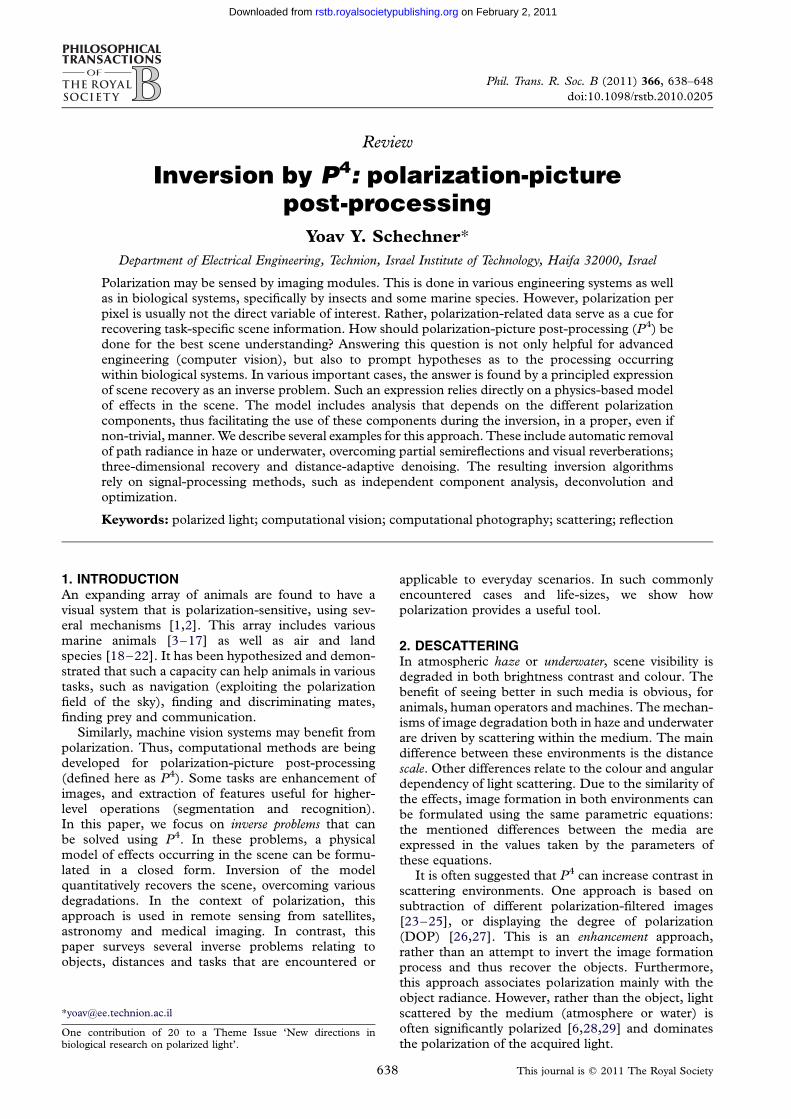
Figure 1. Underwater imaging of a scene through a polarizing filter. Light enters the water and scatters towards the camera by
particles in the water, creating path radiance (dashed rays). This veiling light increases with the distance z to the object. Lightemanating from the object is attenuated and somewhat blurred as z increases, leading to the signal S (solid ray). The partialpolarization of the path radiance is significant. Without scattering and absorption along the line of sight (LOS), the objectradiance would have been Lobject. (Reproduced with permission from [33]. Copyright q IEEE.)
Review. Inversion by P4 Y. Y. Schechner 639
on February 2, 2011rstb.royalsocietypublishing.orgDownloaded from
(a) Model
In this section, we describe a simple model for imageformation in haze or water, including polarization.Then, this model is mathematically inverted to recoverthe object. Polarization plays an important role in thisrecovery task [30–35].
As depicted in figure 1, an image acquired in amedium has two sources. The first source is thescene object at distance z, the radiance of which isattenuated by absorption and scattering. This com-ponent is also somewhat blurred by scattering, butwe neglect this optical blur, as we explain later. Theimage corresponding to this degraded source is thesignal
Sðx; yÞ ¼ Lobjectðx; yÞtðzÞ; ð2:1Þ
where Lobject is the object radiance we would havesensed, had there been no scattering and absorptionalong the line of sight (LOS), and (x,y) are theimage coordinates. Here t(z) is the transmissivity ofthe medium. It monotonically decreases with thedistance z.
The second source is ambient illumination. Part ofthe illumination is scattered towards the camera byparticles in the medium. In the literature, this part istermed path radiance [36], veiling light [6,16,37],spacelight [4,6,16,29] and backscatter [38]. In litera-ture dealing with the atmosphere, it is also termedairlight [39]. This component is denoted by B.It monotonically increases with z. The total imageirradiance is
I total ¼ S þ B: ð2:2Þ
Clearly, B is a positive additive component. It does notocclude the object. So, how come B appears to veil thescene? Furthermore, the image formation model(equations (2.1) and (2.2)) neglects any optical blur.Thus, how come hazy/underwater images appearblurred? The answer to these puzzles is given in
Phil. Trans. R. Soc. B (2011)
Treibitz & Schechner [40]. Due to the quantumnature of light (photons), the additive component Binduces random photon noise in the image. To under-stand this, recall that photon flux from the scene andthe detection of each photon are Poissonian randomprocesses [41]. This randomness yields an effectivenoise. The overall noise variance [41–43] of themeasured pixel intensity is approximately
s2 ¼ k2 þ I total
g: ð2:3Þ
Here k and g are positive constants, which are specificto the sensor. Due to equations (2.2) and (2.3), Bincreases Itotal and thus the noise1 intensity. Thelonger the distance to the object, the larger B is. Con-sequently, the image is more noisy there, making itmore difficult to see small object details (veiling),even if contrast-stretching is applied by image post-processing. As analysed in Treibitz & Schechner [40],image noise creates an effective blur, despite anabsence of blur in the optical process: the recoverablesignal has an effective spatial cutoff frequency, inducedby noise.
To recover Lobject by inverting equation (2.1), thereis first a need to decouple the two unknowns (perimage point) S and B, which are mixed byequation (2.2). This is where P4 becomes helpful.Let images be taken through a camera-mounted polar-izer. As we will see below, polarization provides twoindependent equations, to solve for the two mentionedunknowns. Typically, the path radiance B is partiallypolarized [6,16,23,28,39,44]. Hence, polarization-filtered images can sense smaller or higher intensitiesof the path radiance B, depending on the orientationof the camera-mounted polarizer (figure 1), relative tothe polarization vector of the path radiance. There aretwo orthogonal orientations of the polarizer for whichits transmittance of the path radiance reaches extre-mum values Bmax and Bmin, where B ¼ Bmax þ Bmin.
(a) (b)
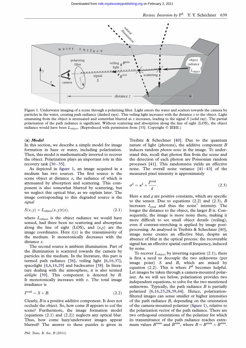
Figure 2. Polarization-based unveiling of a Mediterranean underwater scene under artificial illumination, at night. (a) Rawimage. (b) Recovered signal S. (Reproduced with permission from [35]. Copyright q IEEE.)
640 Y. Y. Schechner Review. Inversion by P4
on February 2, 2011rstb.royalsocietypublishing.orgDownloaded from
At these orientations, the acquired images are
Imax � S
2þ Bmax and Imin � S
2þ Bmin: ð2:4Þ
Equation (2.4) assumes that the polarization of theobject signal is negligible relative to that of the pathradiance. In some cases this assumption may bewrong, particularly at close distances. However, inmany practical cases, the approximation expressed byequation (2.4) leads to effective scene recovery. Thetwo equations (2.4) provide the needed constraints todecouple the two unknowns S and B, as describedin Kaftory et al. [31], Namer et al. [32], Schechneret al. [34] and Treibitz & Schechner [35].
(b) Inversion
The above model applies both to natural lighting(which is roughly uniform along horizontal lines ofsight) and artificial illumination. An example of thelatter is shown in figure 2. Here, a polarizer wasmounted on the light source, and another polarizerwas mounted on the camera. Rotating one of thepolarizers relative to the other yielded two imagesmodelled by equation (2.4). They were processed torecover S.
To recover Lobject by inverting equation (2.1), thereis first a need to know t(z) per point. How can t(z) beassessed? In natural lighting, where the lighting alongthe LOS is roughly uniform [33,34],
B ¼ B1½1� tðzÞ�: ð2:5Þ
Here B1 is the value of B in an LOS which extends toinfinity in the medium. This value can be calibrated insitu [32–35]. Recall that B is recovered using P4.Consequently, based on equations (2.1) and (2.5),the object radiance can be recovered approximately by
Lobjectðx; yÞ �Sðx; yÞ
t½zðx; yÞ�
¼ Sðx; yÞ 1� Bðx; yÞB1
� ��1
: ð2:6Þ
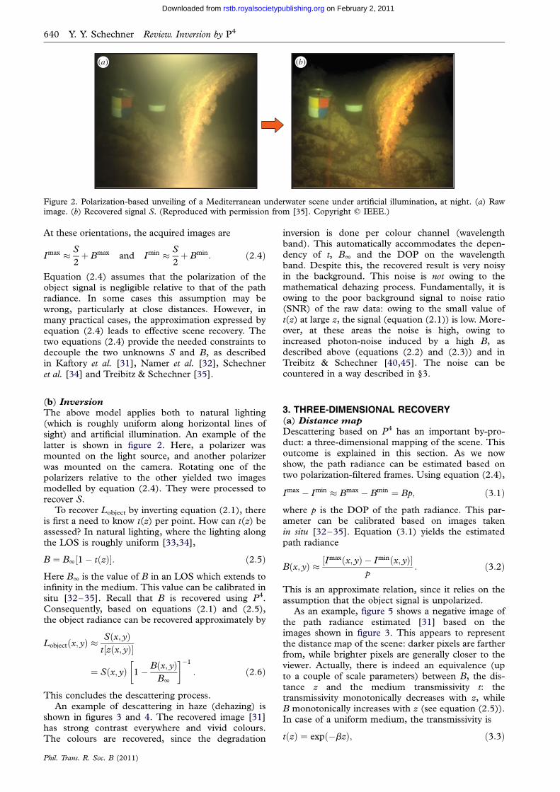
This concludes the descattering process.An example of descattering in haze (dehazing) is
shown in figures 3 and 4. The recovered image [31]has strong contrast everywhere and vivid colours.The colours are recovered, since the degradation
Phil. Trans. R. Soc. B (2011)
inversion is done per colour channel (wavelengthband). This automatically accommodates the depen-dency of t, B1 and the DOP on the wavelengthband. Despite this, the recovered result is very noisyin the background. This noise is not owing to themathematical dehazing process. Fundamentally, it isowing to the poor background signal to noise ratio(SNR) of the raw data: owing to the small value oft(z) at large z, the signal (equation (2.1)) is low. More-over, at these areas the noise is high, owing toincreased photon-noise induced by a high B, asdescribed above (equations (2.2) and (2.3)) and inTreibitz & Schechner [40,45]. The noise can becountered in a way described in §3.
3. THREE-DIMENSIONAL RECOVERY(a) Distance map
Descattering based on P4 has an important by-pro-duct: a three-dimensional mapping of the scene. Thisoutcome is explained in this section. As we nowshow, the path radiance can be estimated based ontwo polarization-filtered frames. Using equation (2.4),
Imax � Imin � Bmax � Bmin ¼ Bp; ð3:1Þ
where p is the DOP of the path radiance. This par-ameter can be calibrated based on images takenin situ [32–35]. Equation (3.1) yields the estimatedpath radiance
Bðx; yÞ � ½Imaxðx; yÞ � Iminðx; yÞ�
p: ð3:2Þ
This is an approximate relation, since it relies on theassumption that the object signal is unpolarized.
As an example, figure 5 shows a negative image ofthe path radiance estimated [31] based on theimages shown in figure 3. This appears to representthe distance map of the scene: darker pixels are fartherfrom, while brighter pixels are generally closer to theviewer. Actually, there is indeed an equivalence (upto a couple of scale parameters) between B, the dis-tance z and the medium transmissivity t: thetransmissivity monotonically decreases with z, whileB monotonically increases with z (see equation (2.5)).In case of a uniform medium, the transmissivity is
tðzÞ ¼ expð�bzÞ; ð3:3Þ
(a) (b)
Figure 3. Polarization filtered images taken on a hazy day. (a)Imax; (b) Imin. (Reproduced with permission from [31].Copyright q IEEE.)
Figure 4. Scene dehazing using equation (2.6), based onimages shown in figure 3. The restoration is noisy, especially
in pixels corresponding to the distant mountain.(Reproduced with permission from [31]. Copyright q IEEE.)
Figure 5. The estimated path radiance. This map is equival-ent to the estimated atmospheric transmissivity, and thus thedistance to each scene point. In this image, dark pixels indi-
cate higher path radiance and thus a larger distance to theobjects shown in figure 3. (Reproduced with permissionfrom [31]. Copyright q IEEE.)
Figure 6. Optimization-based restoration of the scene infigure 3. It regularizes the solution in a way that adapts tothe object distance. The restoration has low noise (comparedwith figure 4), without excessive blur. (Reproduced withpermission from [31]. Copyright q IEEE.)
Review. Inversion by P4 Y. Y. Schechner 641
on February 2, 2011rstb.royalsocietypublishing.orgDownloaded from
where the constant b is the attenuation coefficient ofthe medium. This constant coefficient is inverselyrelated to the attenuation distance in the medium:the scale of b is approximately (0.1–1) m21 under-water and approximately (1024–1023) m21 in haze.
Using equations (2.5), (3.3) and (3.2), the distancemap of the scene, z(x, y), can be estimated as
zðx; yÞ ¼ � 1
bln½tðx; yÞ� ¼ � 1
bln 1� Bðx; yÞ
B1
� �
� � 1
bln 1� Imaxðx; yÞ � Iminðx; yÞ
pB1
� �: ð3:4Þ
Equation (3.4) shows how P4 yields an estimate ofthe distance per image point. This estimation dependson several global parameters (p, b, B1) which canbe assessed based on the image data [32,34,35].The distance map z(x, y) expresses the observedthree-dimensional structure of the scene.
There are additional ways in which P4 can help inthree-dimensional recovery. Shape is often derived
Phil. Trans. R. Soc. B (2011)
using triangulation cues: stereoscopic vision and paral-lax created by motion. It can be helpful to fuse thepolarization cue with triangulation (parallax), whenseeking three-dimensional recovery of a scene in scat-tering media. This is done in Sarafraz et al. [46].Binocular stereo helps the recovery particularly whenthe path radiance has low DOP. On the other hand,polarization helps the recovery irrespective of objecttexture or surface markings to which stereoscopicrecovery is sensitive. Moreover, a stereoscopic setupcan simultaneously acquire two polarization-filteredimages, e.g. using a distinct polarizer orientation percamera. This is helpful in dynamic scenes. Sarafrazet al. [46] models the image formation process by com-bining stereoscopic viewing geometry and scatteringeffects. The recovery is then expressed as inversion ofthis model.
642 Y. Y. Schechner Review. Inversion by P4
on February 2, 2011rstb.royalsocietypublishing.orgDownloaded from
An additional way to exploit triangulation for shaperecovery is by using structured illumination. In thismethod, one of the stereo cameras is replaced by alight source, which projects a narrow beam on thescene. Triangulation between the illuminated objectspot and the LOS yields the object distance, perimage point, while the beam scans the scene. Triangu-lation becomes more complicated in scattering media,owing to backscatter. Hence, Gupta et al. [30] incor-porated backscatter polarization into analysis ofstructured illumination.
(b) Distance adaptation of noise suppression
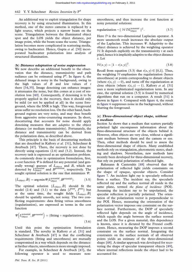
We now describe an additional benefit to the obser-vation that the distance, transmissivity and pathradiance can be estimated using P4. In figure 4, thedehazed image is noisy in the background, owing tothe high values of B and low values of tthere [34,35]. Image denoising can enhance images:it attenuates the noise, but this comes at a cost of res-olution loss [40]. Consequently, if denoising is to beproperly applied in the recovery, then it should onlybe mild (or not be applied at all) in the scene fore-ground, where the SNR is high. This way, foregroundareas suffer no resolution loss. On the other hand, back-ground regions are very noisy, and may thus benefitfrom aggressive noise-countering measures. In short,descattering that accounts for noise should applydenoising measures that are adaptive to the objectdistance (or medium transmissivity). Fortunately, thedistance and transmissivity can be derived fromthe polarization data, as described above.
This principle is the basis of descattering methodsthat are described in Kaftory et al. [31], Schechner &Averbuch [47]. There, the recovery is not done bydirectly using equations (2.6) and (3.2). Instead, therecovery task is expressed as an optimization problem.As commonly done in optimization formulation, first,a cost function C is defined for any potential (and gen-erally wrong) guesses of Lobject and B, which aredenoted by Lobject
potential and Bpotential, respectively. Thesought optimal solution is the one that minimizes C:
fLobject; Bg ¼ arg minCðLpotentialobject ;BpotentialÞ: ð3:5Þ
The optimal solution fLobject; Bg should fit themodel (2.4) and (3.1) to the data fImax, Iming butat the same time, the sought fields fLobject; Bgshould be spatially smooth, not noisy. The two con-flicting requirements: data fitting versus smoothness(regularization), are expressed as terms in the costfunction
C Lpotentialobject ;Bpotential
� �¼ ðfittingþ regularizationÞ:
ð3:6Þ
Until this point the optimization formulationis standard. The novelty in Kaftory et al. [31] andSchechner & Averbuch [47] is that the conflictingrequirements (fitting and smoothness) are mutuallycompromised in a way which depends on the distance:at farther objects, smoothness is more strongly imposed.
For example, in Schechner & Averbuch [47], thefollowing operator is used to measure non-
Phil. Trans. R. Soc. B (2011)
smoothness, and thus increase the cost function atnoisy potential solutions:
regularization �kWDLpotentialobject k2 : ð3:7Þ
Here D is the two-dimensional Laplacian operator. Amore unsmooth result increases the absolute outputof the Laplacian. This increases C. Adaptivity to theobject distance is achieved by the weighting operatorW. It depends explicitly on the transmissivity t at eachpixel, hence it is implicitly adaptive to the object distancez. Let
Wðx; yÞ ¼ ½1� tðx; yÞ�2: ð3:8Þ
Recall from equation (3.3) that t(x, y) [ [0,1]. Thus,the weighting W emphasizes the regularization (hencesmoothness) at points corresponding to distant objects(where t(x, y)! 0), and turns off the regularization atclose objects (where t(x, y)! 1). Kaftory et al. [31]uses a more sophisticated regularization term. In anycase, the optimal solution (3.5) is found by numericalalgorithms that run on a computer. A result [31] isshown in figure 6. Compared with figure 4, the resultin figure 6 suppresses noise in the background, withoutblurring the foreground.
(c) Three-dimensional object shape, without
a medium
Section 3a shows that a medium that scatters partiallypolarized light encompasses information about thethree-dimensional structure of the objects behind it.However, often objects are very close, without a signifi-cant medium between them and the camera or eye.Then, other methods should be used to assess thethree-dimensional shape of objects. Many establishedmethods rely on triangulation, photometric stereo, shad-ing and shadows. Nevertheless, new methods haverecently been developed for three-dimensional recovery,that rely on partial polarization of reflected light.
Rahmann & Canterakis [48] observed that thepolarization of reflected light yields constraints onthe shape of opaque, specular objects. Considerfigure 7. An incident light ray is specularly reflectedfrom a surface. The incident ray, the specularlyreflected ray and the surface normal all reside in thesame plane, termed the plane of incidence (POI).Assuming the incident ray to be unpolarized, thespecular reflection is partially polarized. The orien-tation of the polarization vector is perpendicular tothe POI. Hence, measuring the orientation of thepolarization vector imposes one constraint on the sur-face normal. Furthermore, the DOP of specularlyreflected light depends on the angle of incidence,which equals the angle between the surface normaland the LOS. For a given material, this dependencyis known, since it is dictated by the Fresnel coeffi-cients. Hence, measuring the DOP imposes a secondconstraint on the surface normal. Integrating theconstraints on the surface normals of all observedpoints yields an estimate of the three-dimensionalshape [48]. A similar approach was developed for reco-vering the shape of specular transparent objects [49],where internal reflections inside the object had to beaccounted for.
algorithm
polarizer
t^LD
t||LD
f
f
t^LS
r||LS
LSilluminationsource
object
surfacenormal
camera
diffuse
reflectionspecular
reflection
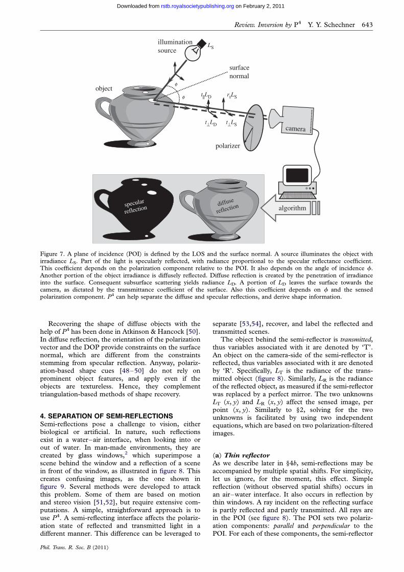
Figure 7. A plane of incidence (POI) is defined by the LOS and the surface normal. A source illuminates the object withirradiance LS. Part of the light is specularly reflected, with radiance proportional to the specular reflectance coefficient.This coefficient depends on the polarization component relative to the POI. It also depends on the angle of incidence f.
Another portion of the object irradiance is diffusely reflected. Diffuse reflection is created by the penetration of irradianceinto the surface. Consequent subsurface scattering yields radiance LD. A portion of LD leaves the surface towards thecamera, as dictated by the transmittance coefficient of the surface. Also this coefficient depends on f and the sensedpolarization component. P4 can help separate the diffuse and specular reflections, and derive shape information.
Review. Inversion by P4 Y. Y. Schechner 643
on February 2, 2011rstb.royalsocietypublishing.orgDownloaded from
Recovering the shape of diffuse objects with thehelp of P4 has been done in Atkinson & Hancock [50].In diffuse reflection, the orientation of the polarizationvector and the DOP provide constraints on the surfacenormal, which are different from the constraintsstemming from specular reflection. Anyway, polariz-ation-based shape cues [48–50] do not rely onprominent object features, and apply even if theobjects are textureless. Hence, they complementtriangulation-based methods of shape recovery.
4. SEPARATION OF SEMI-REFLECTIONSSemi-reflections pose a challenge to vision, eitherbiological or artificial. In nature, such reflectionsexist in a water–air interface, when looking into orout of water. In man-made environments, they arecreated by glass windows,2 which superimpose ascene behind the window and a reflection of a scenein front of the window, as illustrated in figure 8. Thiscreates confusing images, as the one shown infigure 9. Several methods were developed to attackthis problem. Some of them are based on motionand stereo vision [51,52], but require extensive com-putations. A simple, straightforward approach is touse P4. A semi-reflecting interface affects the polariz-ation state of reflected and transmitted light in adifferent manner. This difference can be leveraged to
Phil. Trans. R. Soc. B (2011)
separate [53,54], recover, and label the reflected andtransmitted scenes.
The object behind the semi-reflector is transmitted,thus variables associated with it are denoted by ‘T’.An object on the camera-side of the semi-reflector isreflected, thus variables associated with it are denotedby ‘R’. Specifically, LT is the radiance of the trans-mitted object (figure 8). Similarly, LR is the radianceof the reflected object, as measured if the semi-reflectorwas replaced by a perfect mirror. The two unknownsLT (x, y) and LR (x, y) affect the sensed image, perpoint (x, y). Similarly to §2, solving for the twounknowns is facilitated by using two independentequations, which are based on two polarization-filteredimages.
(a) Thin reflector
As we describe later in §4b, semi-reflections may beaccompanied by multiple spatial shifts. For simplicity,let us ignore, for the moment, this effect. Simplereflection (without observed spatial shifts) occurs inan air–water interface. It also occurs in reflection bythin windows. A ray incident on the reflecting surfaceis partly reflected and partly transmitted. All rays arein the POI (see figure 8). The POI sets two polariz-ation components: parallel and perpendicular to thePOI. For each of these components, the semi-reflector
polarizer
LR
reflectedscene
transmittedscene
LT
window
camerat||LT
r||LR
t^LTr^LR
f
f
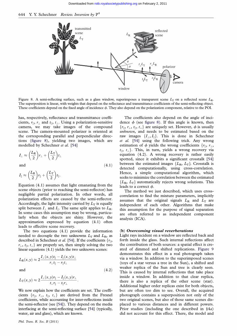
Figure 8. A semi-reflecting surface, such as a glass window, superimposes a transparent scene LT on a reflected scene LR.The superposition is linear, with weights that depend on the reflectance and transmittance coefficients of the semi-reflecting object.These coefficients depend on the fixed angle of incidence f. They also depend on the polarization component, relative to the POI.
644 Y. Y. Schechner Review. Inversion by P4
on February 2, 2011rstb.royalsocietypublishing.orgDownloaded from
has, respectively, reflectance and transmittance coeffi-cients, rjj, r? and tjj, t?. Using a polarization-sensitivecamera, we may take images of the compoundscene. The camera-mounted polarizer is oriented atthe corresponding parallel and perpendicular direc-tions (figure 8), yielding two images, which aremodelled by Schechner et al. [54]
I? �LR
2
� �r? þ
LT
2
� �t?
and
Ik �LR
2
� �rk þ
LT
2
� �tk:
ð4:1Þ
Equation (4.1) assumes that light emanating from thescene objects (prior to reaching the semi-reflector) hasnegligible partial polarization. In other words, allpolarization effects are caused by the semi-reflector.Accordingly, the light intensity carried by LT is equallysplit between I? and Ijj. The same split applies to LR.In some cases this assumption may be wrong, particu-larly when the objects are shiny. However, theapproximation expressed by equation (4.1) oftenleads to effective scene recovery.
The two equations (4.1) provide the informationneeded to decouple the two unknowns LT and LR, asdescribed in Schechner et al. [54]. If the coefficients frjj,r?, tjj, t?g are properly set, then simply solving the twolinear equations (4.1) yields the two unknown scenes:
LRðx; yÞ � 2I?ðx; yÞtk � Ikðx; yÞt?
r?tk � rkt?
and
LTðx; yÞ � 2I?ðx; yÞrk � Ikðx; yÞr?
t?rk � tkr?:
ð4:2Þ
We now explain how the coefficients are set. The coeffi-cients frjj, r?, tjj, t?g are derived from the Fresnelcoefficients, while accounting for inter-reflections insidethe semi-reflector (see [54]). They depend on the mediainterfacing at the semi-reflecting surface [54] (typically,water, air and glass), which are known.
Phil. Trans. R. Soc. B (2011)
The coefficients also depend on the angle of inci-dence f (see figure 8). If this angle is known, thenfrjj, r?, tjj, t?g are uniquely set. However, f is usuallyunknown, and needs to be estimated based on theraw images fI?, Ijjg. This is done in Schechneret al. [54] using the following trick. Any wrongestimation of f yields the wrong coefficients frjj, r?,tjj, t?g. This, in turn, yields a wrong recovery viaequation (4.2). A wrong recovery is rather easilyspotted, since it exhibits a significant crosstalk [54]between the estimated images fLR, LTg. Crosstalk isdetected computationally, using cross-correlation.Hence, a simple computational algorithm, whichseeks to minimize the correlation between the estimatedfLR, LTg automatically rejects wrong solutions. Thisleads to a correct f.
The method we just described, which uses cross-correlation to find the mixture parameters, implicitlyassumes that the original signals LR and LT areindependent of each other. Algorithms that makethis assumption for the purpose of signal separationare often referred to as independent componentanalysis (ICA).
(b) Overcoming visual reverberations
Light rays incident on a window are reflected back andforth inside the glass. Such internal reflections affectthe contribution of both sources: a spatial effect is cre-ated of dimmed and shifted replications. Figure 9demonstrates this effect in a real photograph takenvia a window. In addition to the superimposed scenes(toys of a star versus a tree in the Sun), a shifted andweaker replica of the Sun and tree is clearly seen.This is caused by internal reflections that take placeinside a window. In addition to that clear replica,there is also a replica of the other scene (star).Additional higher order replicas exist for both objects,but are often too dim to see. Overall, the acquiredphotograph contains a superposition not only of thetwo original scenes, but also of those same scenes dis-placed to various distances and in different powers.Prior studies (including the one described in §4a)did not account for this effect. There, the model and
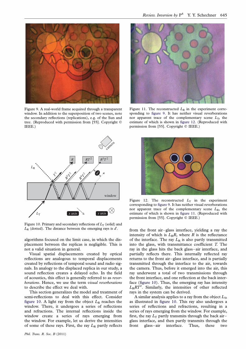
Figure 9. A real-world frame acquired through a transparentwindow. In addition to the superposition of two scenes, notethe secondary reflections (replications), e.g. of the Sun andtree. (Reproduced with permission from [55]. Copyright q
IEEE.)
R RT 2 R3T 2
window
LR
LT
T2
R2 T
2
R4 T
2 d¢
camera
x axis y axis
Figure 10. Primary and secondary reflections of LT (solid) andLR (dotted). The distance between the emerging rays is d0.
Figure 12. The reconstructed LT in the experimentcorresponding to figure 9. It has neither visual reverberations
nor apparent trace of the complementary scene LR, theestimate of which is shown in figure 11. (Reproduced withpermission from [55]. Copyright q IEEE.)
Figure 11. The reconstructed LR in the experiment corre-sponding to figure 9. It has neither visual reverberationsnor apparent trace of the complementary scene LT, theestimate of which is shown in figure 12. (Reproduced with
permission from [55]. Copyright q IEEE.)
Review. Inversion by P4 Y. Y. Schechner 645
algorithms focused on the limit case, in which the dis-placement between the replicas is negligible. This isnot a valid situation in general.
Visual spatial displacements created by opticalreflections are analogous to temporal displacementscreated by reflections of temporal sound and radio sig-nals. In analogy to the displaced replica in our study, asound reflection creates a delayed echo. In the fieldof acoustics, this effect is generally referred to as rever-berations. Hence, we use the term visual reverberationsto describe the effect we deal with.
This section generalizes the model and treatment ofsemi-reflections to deal with this effect. Considerfigure 10. A light ray from the object LR reaches thewindow. There, it undergoes a series of reflectionsand refractions. The internal reflections inside thewindow create a series of rays emerging fromthe window. For example, let us derive the intensitiesof some of these rays. First, the ray LR partly reflects
Phil. Trans. R. Soc. B (2011)
from the front air–glass interface, yielding a ray theintensity of which is LRR, where R is the reflectanceof the interface. The ray LR is also partly transmittedinto the glass, with transmittance coefficient T. Theray in the glass hits the back glass–air interface, andpartially reflects there. This internally reflected rayreturns to the front air–glass interface, and is partiallytransmitted through the interface to the air, towardsthe camera. Thus, before it emerged into the air, thisray underwent a total of two transmissions throughthe front interface, and one reflection at the back inter-face (figure 10). Thus, the emerging ray has intensityLRRT2. Similarly, the intensities of other reflectedrays in the system can be derived.
A similar analysis applies to a ray from the object LT,as illustrated in figure 10. This ray also undergoes aseries of reflections and refractions, resulting in aseries of rays emerging from the window. For example,first, the ray LT partly transmits through the back air–glass interface, and then partly transmits through thefront glass–air interface. Thus, these two
646 Y. Y. Schechner Review. Inversion by P4
on February 2, 2011rstb.royalsocietypublishing.orgDownloaded from
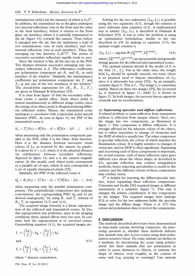
transmissions yield a ray the intensity of which is LTT2.In addition, the transmitted ray in the glass undergoestwo internal reflections (one in the front and the otherin the back interface), before it returns to the frontglass–air interface, where it is partially transmitted tothe air (figure 10), towards the camera. Thus, beforeit emerged into the air, this ray underwent a total oftwo transmissions (one at each interface) and twointernal reflections (one at each interface). Thus, theemerging ray has intensity LTR2T2. The power ofsuccessive secondary reflections rapidly tends to zero.
Since the window is flat, all the rays are in the POI.The distance between successive emerging rays (sec-ondary reflections) is d0. The reflectance coefficientsper polarization component are R? and Rjj, at eachinterface of the window.3 Similarly, the transmittancecoefficients per polarization component are T? andTjj, at any one of the two interfaces of the window.4
The closed-form expressions for fRjj, R?, Tjj, T?gare given in Diamant & Schechner [55].
It is clear from figure 10 that the secondary reflec-tions create a spatial effect. Each object point issensed simultaneously in different image points, sincethe energy of an object point is dissipated among differ-ent reflection orders. Hence, the transmitted sceneundergoes a convolution with a particular point-spreadfunction (PSF). As seen in figure 10, the PSF of thetransmitted scene is
hkT ¼ T 2
k ½dðxÞ þ R2kdðx� dÞ þ R4
kdðx� 2dÞ . . .�; ð4:3Þ
when measuring only the polarization component par-allel to the POI, while d is the Dirac delta function.Here d is the distance between successive visualechoes of LT, as received by the camera (in pixels).It is given by d ¼ a d0, where d0 is the physical distance(in centimetres) between secondary reflections,depicted in figure 10, and a is the camera magnifi-cation. In this model, each object point correspondsto a parallel set of rays, which in turn corresponds toa set of equally interspaced pixels [55].
Similarly, the PSF of the reflected scene is
hkR ¼ Rk½dðxÞ þ T2
k dðx� dÞ þ T 2kR2kdðx� 2dÞ . . .�; ð4:4Þ
when measuring only the parallel polarization com-ponent. The perpendicular components also undergoconvolutions: the corresponding PSFs hR
? and hT? are
derived analogously,5 by using R? and T? instead ofRjj, Tjj in equations (4.3) and (4.4).
The acquired image intensity is a linear superposi-tion of the reflected and transmitted scenes. In §4a,this superposition was pointwise, since in the imagingconditions there, spatial effects were not seen. In con-trast, here the superposition is of convolved scenes.Generalizing equation (4.1), the acquired images are
I? �LR
2
� �� h?R þ
LT
2
� �� h?T
and
Ik �LR
2
� �� hkR þ
LT
2
� �� hkT;
ð4:5Þ
where * denotes convolution.
Phil. Trans. R. Soc. B (2011)
Solving for the two unknowns fLR, LTg is possibleusing the two equations (4.5), though the solution ismore elaborate than equation (4.2). A mathematicalway to extract fLR, LTg is described in Diamant &Schechner [55]. A way to solve the problem is usingan optimization formulation, similar to the onedescribed in §3b. In analogy to equation (3.5), theoptimal sought solution is
fLR;LTg ¼ arg minC ðLpotentialR ;Lpotential
T Þ; ð4:6Þ
wherefLRpotential,LT
potentialg areanypotential (and generallywrong) guesses for the reflected and transmitted scenes.
The optimal solution should fit the model (4.5) tothe data fI?, Ijjg, but at the same time, the soughtfield LR should be spatially smooth, not noisy (thereis no practical need to impose smoothness on LT,since it is inherently less noisy [55]). As an example,consider figure 9. This is I?. The image Ijj is somewhatsimilar. Based on these two images [55], the recoveredLR is depicted in figure 11, while LT is shown infigure 12. In both images, the recovery has no apparentcrosstalk and no reverberations.
(c) Separating specular and diffuse reflections
A related problem to semi-reflection from transparentsurfaces is reflection from opaque objects. Here, too,the image has two components, as illustrated infigure 7. One component is diffuse reflection. It isstrongly affected by the inherent colour of the object,but is rather insensitive to change of viewpoint andthe DOP of which is usually low. The other componentis specular reflection, the colour of which matches theillumination colour. It is highly sensitive to changes ofviewpoint, and its DOP is often significant. Separatingand recovering each of these components is important,for several reasons: each of these reflection types givesdifferent cues about the object shape, as described in§3c; specular reflection may confuse triangulationmethods, hence removing specularities is useful in thiscontext; and the different colours of these componentsmay confuse vision.
P4 is helpful for inverting the diffuse/specular mix-ture, hence separating these reflection components.Umeyama and Godin [56] acquired images at differentorientations of a polarizer (figure 7). This way, itchanges the relative contribution of two componentsin the images. The acquired images then undergoICA to solve for the two unknown fields: the specularimage and the diffuse image. Nayar et al. [57] fusecolour and polarization data to recover the components.
5. DISCUSSIONThe methods described above have been demonstratedin man-made systems involving computers. An inter-esting question is, whether these methods indicatethat animals may also recover scenes using their polar-ization-sensitive vision. Do some animals see farther ina medium, by descattering the scene using polariz-ation? Are there animals that use polarization inorder to assess distances to objects, or estimate theshape of objects, even roughly, in the context ofsome task (e.g. preying or courting)? Can animals
Review. Inversion by P4 Y. Y. Schechner 647
on February 2, 2011rstb.royalsocietypublishing.orgDownloaded from
that prey through the surface of seas or lakes (somebirds, fish, crocodiles), upwards or downwards, usepolarization in order to remove semi-reflections fromthe surface? Perhaps polarization is used for separatingspecular from diffuse reflection [19] in nature toprovide an advantage in seeking food in the open air?
It is also possible to consider exploitation of theseeffects to confuse predators. Suppose a predator usespath-radiance polarization for distance assessment.Then, a marine animal that has a polarizing skinwould confuse this distance assessment, hence gainingan advantage in avoiding attack by the predator. Theseare fascinating questions and possibilities. Biologicalsystems do not work as the computational algorithmsdescribed in this paper. But, the algorithms provefeasibility: some computational systems can recoverscenes using polarization. Biological brains are alsocomputational systems. Perhaps they do it too.
This paper surveys the work I have done with severalcoauthors to whom I am grateful: Yuval Averbuch, YaronDiamant, Ran Kaftory, Nir Karpel, Nahum Kiryati, MohitGupta, Einav Namer, Shahriar Negahdaripour, AminSarafraz, Srinivas Narasimhan, Shree Nayar, JosephShamir, Sarit Shwartz, Tali Treibitz and Yehoshua Zeevi.Thanks are also due to Justin Marshall, David O’Carroll,Nick Roberts and Nadav Shashar, for the usefuldiscussions at the 2008 Heron Island PolarizationConference. Their insights into the potential relevance toanimal vision come across in this paper. Yoav Schechner isa Landau Fellow - supported by the Taub Foundation.This work is supported by the Israel Science Foundation(Grant 1031/08) and the US-Israel Binational ScienceFoundation (BSF) Grant 2006384. This work wasconducted in the Ollendorff Minerva Center. Minerva isfunded through the BMBF. This work relates toDepartment of the Navy Grant N62909-10-1-4056 issuedby the office of Naval Research Global. The United StatesGovernment has a royalty-free license throughout theworld in all copyrightable material contained herein.
ENDNOTES1The increase in the intensity (variance) of the noise is not only rela-
tive to the signal S. Rather, the absolute level of the noise intensity
increases with B, owing to equations (2.2) and (2.3).2Semi-reflections are also created by plastic windows. However, trans-
parent plastic materials are more prone than glass to the photoelastic
effect [33]. In this effect, stress in the transparent material changes the
polarization of light propagating inside the window. This may confuse
polarization-based methods for separation of semi-reflections.3These are not the coefficients r? and rjj used in §4a. The relation
between any r and its corresponding R will become clear in the
following discussion.4These are not the coefficients t? and tjj used in §4a, since t? and tjjexpress the overall transmittance of light through the combined
effect of both window interfaces.5Note that if d � 0 (thin window), the scene and model analysed in
this section degenerate to those discussed in §4a. Specifically, if d ¼
0, equation (4.3) degenerates to hTjj ¼ tjj d (x), where tjj is a transmit-
tance used in §4a. In other words, tjj ¼ Tjj2(1 þ Rjj
2 þ Rjj4 . . .).
Similarly, the other coefficients ft?, rjj, r?g used in §4a are obtained
by using d ¼ 0 in hT? , hR
jj and hR?, respectively.
REFERENCES1 Fischer, L., Zvyagin, A., Plakhotnik, T. & Vorobyev, M.
2010 Numerical modeling of light propagation in a hex-
agonal array of dielectric cylinders. J. Opt. Soc. Am. A 27,865–872. (doi:10.1364/JOSAA.27.000865)
Phil. Trans. R. Soc. B (2011)
2 Kleinlogel, S. & Marshall, N. J. 2009 Ultraviolet pol-arisation sensitivity in the stomatopod crustaceanOdontodactylus scyllarus. J. Comp. Physiol. A 195, 1153–
1162. (doi:10.1007/s00359-009-0491-y)3 Cronin, T. W., Shashar, N., Caldwell, R. L., Marshall, J.,
Cheroske, A. G. & Chiou, T. H. 2003 Polarization visionand its role in biological signaling. Integr. Comp. Biol. 43,549–558. (doi:10.1093/icb/43.4.549)
4 Horvath, G. & Varju, D. 2004 Polarized light in animalvision. Berlin, Germany: Springer.
5 Johnsen, S. 2000 Transparent animals. Sci. Am. 282,80–89. (doi:10.1038/scientificamerican0200-80)
6 Lythgoe, J. N. 1972 The adaptation of visual pigments tothe photic environment. In Handbook of sensory physi-ology, VII/1 (ed. H. J. A. Dartnall), pp. 566–603.Berlin, Germany: Springer.
7 Mathger, L. M., Shashar, N. & Hanlon, R. T. 2009 Do
cephalopods communicate using polarized light reflec-tions from their skin? J. Environ. Biol. 212, 2133–2140.(doi:10.1242/jeb.020800)
8 Michinomae, M., Masuda, H., Seidou, M. & Kito, Y.1994 Structural basis for wavelength discrimination in
the banked retina of the firefly squid Watasenia scintillans.J. Environ. Biol. 193, 1–12.
9 Parkyn, D. C., Austin, J. D. & Hawryshyn, C. W. 2003Acquisition of polarized-light orientation in salmonidsunder laboratory conditions. Anim. Behav. 65, 893–904.
(doi:10.1006/anbe.2003.2136)10 Roberts, N. W., Chiou, T.-H., Marshall, N. J. & Cronin,
T. W. 2009 A biological quarter-wave retarder withexcellent achromaticity in the visible wavelength
region. Nat. Photon. 3, 641–644. (doi:10.1038/npho-ton.2009.189)
11 Roberts, N. W., Gleeson, H. F., Temple, S. E, Haimberger,T. J. & Hawryshyn, C. W. 2004 Differences in the opticalproperties of vertebrate photoreceptor classes leading
to axial polarization sensitivity. J. Opt. Soc. Am. A 21,335–345. (doi:10.1364/JOSAA.21.000335)
12 Roberts, N. W. & Needham, M. G. 2007 A mechanismof polarized light sensitivity in cone photoreceptors ofthe goldfish Carassius auratus. Biophys. J. 93, 3241–3248.
(doi:10.1529/biophysj.107.112292)13 Sabbah, S., Lerner, A., Erlick, C. & Shashar, N. 2005
Under water polarization vision—a physical examination.Recent Res. Dev. Exp. Theor. Biol. 1, 1–53.
14 Shashar, N. & Cronin, T. W. 1996 Polarization
contrast vision in octopus. J. Environ. Biol. 199,999–1004.
15 Waterman, T. H. 1981 Polarization sensitivity. InHandbook of sensory physiology, VII/6B (ed. H. J. A.
Dartnall), pp. 281–469. Berlin, Germany: Springer.16 Wehner, R. 2001 Polarization vision—a uniform sensory
capacity? J. Environ. Biol. 204, 2589–2596.17 Wolff, L. B. 1997 Polarization vision: a new sensory
approach to image understanding. Image Vis. Comp. 15,
81–93. (doi:10.1016/S0262-8856(96)01123-7)18 Dacke, M., Nilsson, D.-E., Warrant, E. J., Blest, A. D.,
Land, M. F. & O’Carroll, D. C. 1999 Built-in polarizersform part of a compass organ in spiders. Nature 401,470–473. (doi:10.1038/46773)
19 Kelber, A., Thunell, S. & Arikawa, K. 2001 Polarisation-dependent colour vision in papilio butterflies. J. Environ.Biol. 204, 2469–2480.
20 Labhart, T. & Meyer, E. P. 2002 Neural mechanisms ininsect navigation: polarization compass and odometer.
Curr. Opin. Neurobiol. 12, 707–714. (doi:10.1016/S0959-4388(02)00384-7)
21 Muheim, R., Phillips, J. B. & Akesson, S. 2006 Polarizedlight cues underlie compass calibration in migratorysongbirds. Nature 313, 837–839.

648 Y. Y. Schechner Review. Inversion by P4
on February 2, 2011rstb.royalsocietypublishing.orgDownloaded from
22 Sweeney, A., Jiggins, C. & Johnsen, S. 2003 Insect com-munication: polarized light as a butterfly mating signal.Nature 423, 31–32. (doi:10.1038/423031a)
23 Chang, P. C. Y., Flitton, J. C., Hopcraft, K. I., Jakeman, E.,Jordan, D. L. & Walker, J. G. 2003 Improving visibilitydepth in passive underwater imaging by use of polariz-ation. Appl. Opt. 42, 2794–2802. (doi:10.1364/AO.42.002794)
24 Denes, L. J., Gottlieb, M., Kaminsky, B. & Metes, P.1999 AOTF polarization difference imaging. Proc. SPIE3584, 106–115. (doi:10.1117/12.339812)
25 Harsdorf, S., Reuter, R. & Toneon, S. 1999 Contrast-
enhanced optical imaging of submersible targets. Proc.SPIE 3821, 378–383. (doi:10.1117/12.364201)
26 Rowe, M. P., Pugh Jr, E. N., Tyo, J. S. & Engheta, N.1995 Polarization-difference imaging: a biologicallyinspired technique for observation through scattering
media. Opt. Lett. 20, 608–610. (doi:10.1364/OL.20.000608)
27 Taylor Jr, J. S. & Wolff, L. B. 2001 Partial polarizationsignature results from the field testing of the shallowwater real-time imaging polarimeter (SHRIMP). Proc.MTS/IEEE Oceans 1, 107–116.
28 Konnen, G. P. 1985 Polarized light in nature. New York,NY: Cambridge University Press.
29 Lythgoe, J. N. & Hemmings, C. C. 1967 Polarized lightand underwater vision. Nature 213, 893–894. (doi:10.
1038/213893a0)30 Gupta, M., Narasimhan, S. G. & Schechner, Y. Y. 2008
On controlling light transport in poor visibility environ-ments. Proc. IEEE Conf. on Computer Vision and PatternRecognition, Anchorage, AK, 23–28 June 2008.
31 Kaftory, R., Schechner, Y. Y. & Zeevi, Y. Y. 2007 Vari-ational distance dependent image restoration. Proc.IEEE Conf. on Computer Vision and Pattern Recognition,Minneapolis, MN, 17–22 June 2007.
32 Namer, E., Shwartz, S. & Schechner, Y. Y. 2009Skyless polarimetric calibration and visibility enhance-ment. Opt. Exp. 17, 472–493. (doi:10.1364/OE.17.000472)
33 Schechner, Y. Y. & Karpel, N. 2005 Recovery of under-
water visibility and structure by polarization analysis.IEEE J. Ocean. Eng. 30, 570–587.
34 Schechner, Y. Y., Narasimhan, S. G. & Nayar, S. K. 2003Polarization-based vision through haze. Appl. Opt. 42,511–525. (doi:10.1364/AO.42.000511)
35 Treibitz, T. & Schechner, Y. Y. 2009 Active polarizationdescattering. IEEE Trans. Pattern Anal. Mach. Intell. 31,385–399. (doi:10.1109/TPAMI.2008.85)
36 Jerlov, N. G. 1976 Marine optics. Amsterdam, TheNetherlands: Elsevier.
37 Shashar, N., Hagan, R., Boal, J. G. & Hanlon, R. T.2000 Cuttlefish use polarization sensitivity in predationon silvery fish. Vis. Res. 40, 71–75. (doi:10.1016/S0042-6989(99)00158-3)
38 Jaffe, J. S. 1990 Computer modelling and the design ofoptimal underwater imaging systems. IEEE J. Ocean.Eng. 15, 101–111.
39 Lynch, D. K. & Livingston, W. 2001 Color and light innature, 2nd edn. Cambridge, UK: Cambridge University
Press.40 Treibitz, T. & Schechner, Y. Y. 2009 Recovery limits in
pointwise degradation. Proc. IEEE Int. Conf. on Compu-tational Photography, San Francisco, CA, 16–17 April 2009.
Phil. Trans. R. Soc. B (2011)
41 Inoue, S. & Spring, K. R. 1997 Video microscopy, 2ndedn., ch. 6–8. New York, NY: Plenum Press.
42 Barrett, H. H. & Swindell, W. 1981 Radiological imaging,
vol. 1. New York, NY: Academic Press.43 Ratner, N., Schechner, Y. Y. & Goldberg, F. 2007 Opti-
mal multiplexed sensing: bounds, conditions and a graphtheory link. Opt. Exp. 15, 17 072 – 17 092. (doi:10.1364/OE.15.017072)
44 Kattawar, G. W. & Rakovic, M. J. 1999 Virtues of Muel-ler matrix imaging for underwater target detection. Appl.Opt. 38, 6431–6438. (doi:10.1364/AO.38.006431)
45 Treibitz, T. & Schechner, Y. Y. 2009 Polarization:
beneficial for visibility enhancement? Proc. IEEE Conf.on Computer Vision and Pattern Recognition, Miami, FL,20–25 June 2009.
46 Sarafraz, A., Negahdaripour, S. & Schechner, Y. Y. 2009Enhancing images in scattering media utilizing stereovi-
sion and polarization. Proc. IEEE Workshop onApplications of Computer Vision.
47 Schechner, Y. Y. & Averbuch, Y. 2007 Regularized imagerecovery in scattering media. IEEE Trans. Pattern Anal.Mach. Intell. 29, 1655–1660. (doi:10.1109/TPAMI.
2007.1141)48 Rahmann, S. & Canterakis, N. 2001 Reconstruction of
specular surfaces using polarization imaging. Proc.IEEE Conf. on Computer Vision and Pattern Recognition,149–155
49 Miyazaki, D. & Ikeuchi, K. 2007 Shape estimation oftransparent objects by using inverse polarization raytracing. IEEE Trans. Pattern Anal. Mach. Intell. 29,2018–2029. (doi:10.1109/TPAMI.2007.1117)
50 Atkinson, G. A. & Hancock, E. R. 2007 Shape esti-mation using polarization and shading from two views.IEEE Trans. Pattern Anal. Mach. Intell. 29, 2001–2017.(doi:10.1109/TPAMI.2007.1099)
51 Be’ery, E. & Yeredor, A. 2008 Blind separation of
superimposed shifted images using parameterized jointdiagonalization. IEEE Trans. Image Process. 17, 340–353.(doi:10.1109/TIP.2007.915548)
52 Tsin, Y., Kang, S. B. & Szeliski, R. 2006 Stereo matchingwith linear superposition of layers. IEEE Trans. PatternAnal. Mach. Intell. 28, 290–301. (doi:10.1109/TPAMI.2006.42)
53 Farid, H. & Adelson, E. H. 1999 Separating reflectionsfrom images by use of independent component analysis.J. Opt. Soc. Am. A 16, 2136–2145. (doi:10.1364/
JOSAA.16.002136)54 Schechner, Y. Y., Shamir, J. & Kiryati, N. 2000 Polariz-
ation and statistical analysis of scenes containing asemi-reflector. J. Opt. Soc. Am. A 17, 276–284.
(doi:10.1364/JOSAA.17.000276)55 Diamant, Y. & Schechner, Y. Y. 2008 Overcoming
visual reverberations. Proc. IEEE Conf. on ComputerVision and Pattern Recognition, Anchorage, AK, 23–28June 2008.
56 Umeyama, S. & Godin, G. 2004 Separation of diffuseand specular components of surface reflection by use ofpolarization and statistical analysis of images. IEEETrans. Pattern Anal. Mach. Intell. 26, 639–647. (doi:10.1109/TPAMI.2004.1273960)
57 Nayar, S. K., Fang, X. & Boult, T. 1997 Separation ofreflection components using color and polarization.Int. J. Comput. Vis. 21, 163–186. (doi:10.1023/A:1007937815113)


![1 Calibration of Anisotropic Velocity Models using ... · Horne, S. and Leaney, S. [2000] Short note: Polarization and slowness component inversion for TI anisotropy. Geophysical](https://img.pdfslide.us/doc/110x75/5edab89f272674784f04f501/1-calibration-of-anisotropic-velocity-models-using-horne-s-and-leaney-s.jpg)