Embed Size (px)
Citation preview
INVERSE RADIATION DESIGN PROBLEMIN A TWO-DIMENSIONAL RADIATIVELY ACTIVECYLINDRICAL MEDIUM USING AUTOMATICDIFFERENTIATION AND BROYDEN COMBINED UPDATE
Ki Wan Kim and Seung Wook BaekDivision of Aerospace Engineering, Department of Mechanical Engineering,Korea Advanced Institute of Science and Technology, Yuseong-Gu, Taejon,Republic of Korea
Inverse radiation design analysis in a two-dimensional, concentric, cylindrical, absorbing,
emitting and scattering medium has been conducted, given desired boundary conditions
on the design surface. The finite-volume method was adopted to solve the radiative transfer
equation and the energy conservation equation in the direct problem, while the Levenberg-
Marquardt method was used to solve a set of equations, which are expressed by errors
between estimated and desired radiative heat fluxes on the design surface. In order to dim-
inish the computational time required for calculating sensitivity matrix, automatic differen-
tiation as well as the Broyden combined update were utilized.
INTRODUCTION
Inverse radiation analysis has been utilized to estimate radiative propertieswhen the other measured radiative data were available or to deduce the optimalcondition satisfying a design goal [1]. In the former case, medium properties suchas extinction coefficient, absorption coefficient, single scattering albedo, phase func-tion, optical depth, and temperature, as well as surface properties such as boundaryemissivity and temperature, have been estimated from measured intensities exitingfrom the boundary or temperature inside the medium [2–6]. This concept has alsobeen applied to optical tomography for examining cross-sectional images of thehuman body in medical science [7]. In the latter case, boundary or source designproblems have been solved to find optimal distribution of boundary condition orsource strength satisfying the desired condition on design surfaces in irregular as wellas regular geometries containing either a nonparticipating or a gray participatingmedium [8–12]. However, cylindrical geometry problems have not attracted as much
Received 1 October 2005; accepted 23 November 2005.
The financial assistance by the Combustion Engineering Research Center at the Korea Advanced
Institute of Science and Technology is gratefully acknowledged.
Address correspondence to Seung Wook Baek, Division of Aerospace Engineering, Department of
Mechanical Engineering, Korea Advanced Institute of Science and Technology, 373-1 Guseong-Dong,
Yuseong-Gu, Daejeon 305-701, Republic of Korea. E-mail: [email protected]
525
Numerical Heat Transfer, Part A, 50: 525–543, 2006
Copyright # Taylor & Francis Group, LLC
ISSN: 1040-7782 print=1521-0634 online
DOI: 10.1080/10407780600599331
attention [12], while the scattering term in the radiative transfer equation was nottaken into account either [10, 11].
Various inverse methods have been adopted to obtain a stable solution in spiteof the ill-posed characteristic of inverse problems. Even though matrix solver-basedmethods do not need an iteration procedure, special treatment is required to dealwith the ill-conditioned nature of the equations [8, 9]. On the other hand, optimiza-tion technique-based methods are emerging as a stable inverse method due tomultidimensionality as well as complexity in inverse problems [2–7, 10, 11].
A successful estimation of unknown properties depends on the magnitude ofthe sensitivity coefficient. The bigger its magnitude, the easier it is to estimate theinverse solutions. Furthermore, a reduction in computational time for calculatingthose values is one of the main issues in gradient-based optimization technique.The sensitivity method deals with the calculation of sensitivity coefficients. So far,equation-based sensitivity methods, such as sensitivity problems [1, 4, 5], bound-ary-value problems [1, 10], or adjoint problems [1], have been prevalent. Recently,code-based methods have received much attention due to their advantages [7]. Thesemethods do not need to derive an adjoint problem or a sensitivity problem, so adiscretization procedure of relevant equations is not necessary. Computational code
NOMENCLATURE
Dmci direction weights
~eex;~eey;~eez unit vector in x, y, z directions
Eb emissive power ð¼pIbÞ; W=m2
I radiation intensity, W=m2 sr
Ib blackbody radiation intensity,
W=m2 sr
L cylinder height, m~nni unit vector normal to control-volume
surface i
ne number of elements on design surface
nh number of heaters
np number of unknown parameters
P a vector of unknown parameters
qR radiative heat flux, W=m2
~rr position vector of intensity
rin inner cylinder radius, m
rout outer cylinder radius, m
s_
direction vector of intensity
S equations set
T temperature of participating
medium, K
Ti boundary temperature at the surface i
X sensitivity matrix
bo extinction coefficient
ð¼ja þ rsÞ; m�1
DAi ;DV ith surface area and volume of the
control volume
DX control angle
ei boundary emissivity at the surface i
h polar angle measured from the z
direction, rad
H nondimensional medium temperature
ja absorption coefficient, m�1
rs scattering coefficient, m�1
uo space variable in the azimuthal
direction measured from x axis, rad
uX angular variable in the azimuthal
direction measured from x0 axis, rad
U scattering phase function
xo single scattering albedo
Subscripts
d design surface
e estimated value
e; w; n; s; t; b index of control-volume
surfaces
E; W ; N; S; T ; B index of neighboring
nodal points
h heater surface
P calculating nodal point
R radiation
ref reference value
w wall
Superscripts
k iteration number
m; m0 radiation direction
mþ; m� boundaries of the control volume
* nondimensional quantity
526 K. W. KIM AND S. W. BAEK
for the sensitivity matrix can be extracted directly from the code of the direct prob-lem. Automatic differentiation belongs to this category.
The goal of this study is to reduce the computational time for calculating thesensitivity matrix. Our previous study shows that the effect of the precision ofthe sensitivity matrix on estimation accuracy is not crucial [13]. Because of this, theBroyden combined update, which is one of the secant methods, is used with auto-matic differentiation to further shorten the computational time required to calculatethe sensitivity matrix.
Therefore, the major contribution of this work is to propose automatic differ-entiation with Broyden combined update as an alternative sensitivity method and toextend the inverse radiation design problem to a two-dimensional cylindrical enclos-ure as a successful application.
ANALYSIS AND MODELING
Model Description
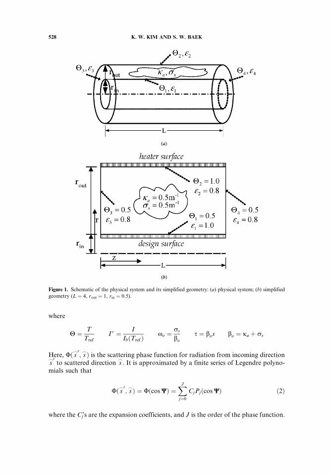
Figure 1 shows a concentric cylindrical enclosure which is filled with anabsorbing, emitting, and scattering gray medium, and its simplified geometry withboundary conditions. The walls are diffusely emitting and reflecting gray walls.
The direct problem is to calculate the radiative heat flux distribution on thedesign surface, given boundary conditions, such as temperature, wall emissivity, andmedium properties such as absorption and scattering coefficient. The temperaturedistribution inside the medium is determined by solving the energy conservationequation in radiative equilibrium, since radiation is the only dominant heat transferin this work. Radiative heat flux over the wall including the heater surface isobtained by integrating the dot product of intensity and the unit normal vector overall solid angles, while the intensity distribution is acquired by solving the radiativetransfer equation. In this work, the finite-volume method is adopted for solvingthe radiative transfer equation.
In the inverse problem, the goal is to find the radiative heat flux distributionover the heater surface which satisfies the desired radiative heat flux as well as tem-perature on the design surface. The Levenberg-Marquardt method is used to solve aset of equations expressed by errors between the estimated and desired radiative heatflux on the design surface. In order to reduce the computing time for the sensitivitymatrix, a combined method of automatic differentiation and Broyden combinedupdate is adopted in this study. Detailed description of mathematical formulationsand numerical methods used in this work is given below.
Radiative Transfer Equation
The nondimensionalized radiative transfer equation (RTE) governing radi-ation intensity for a gray medium at any position ~rr along a path s
_through an
absorbing, emitting, and scattering medium is given by
dI�ð~rr; s_Þ
dsþ I�ð~rr; s
_Þ ¼ ð1� xoÞH4ð~rrÞ þ xo
4p
Z4p
Uð s_0; s_ÞI�ð~rr; s
_ÞdX0 ð1Þ
INVERSE RADIATION DESIGN PROBLEM 527
where
H ¼ T
TrefI� ¼ I
IbðTrefÞxo ¼
rs
bo
s ¼ bos bo ¼ ja þ rs
Here, Uð s_0; s_Þ is the scattering phase function for radiation from incoming direction
s_0
to scattered direction s_
. It is approximated by a finite series of Legendre polyno-mials such that
Uð s_0; s_Þ ¼ Uðcos WÞ ¼
XJ
j¼0
CjPjðcos WÞ ð2Þ
where the Cj’s are the expansion coefficients, and J is the order of the phase function.
Figure 1. Schematic of the physical system and its simplified geometry: (a) physical system; (b) simplified
geometry (L ¼ 4, rout ¼ 1, rin ¼ 0.5).
528 K. W. KIM AND S. W. BAEK
The boundary condition for a diffusely emitting and reflecting wall can bewritten as
I�ð~rrw; s_Þ ¼ ewð~rrwÞH4ð~rrwÞ þ
1� ewð~rrwÞp
Zs_0�~nnw<0
I�ð~rrw; s_0Þj s_0 �~nnwj dX0 ð3Þ
where ew is the wall emissivity and~nnw, which has a positive value when the ray travelsfrom the wall to medium, is the unit normal vector to the wall. Equation (3) can alsobe expressed as a form of prescribed radiative heat flux:
I�ð~rrw; s_Þ ¼ q�Rð~rrwÞ þ
1
p
Zs_0�~nnw<0
I�ð~rrw; s_0Þj s_0 �~nnwj dX0 ð4Þ
Here, nondimensional heat flux is q�R ¼ qR=rT4ref .
The radiative heat flux on the design surface is calculated as follows:
q�Rð~rrw;dÞ ¼1
p
ZX¼4p
I�ð~rrw; s_Þð~nnw;d � s
_Þ dX ð5Þ
Finite-Volume Method for Radiation
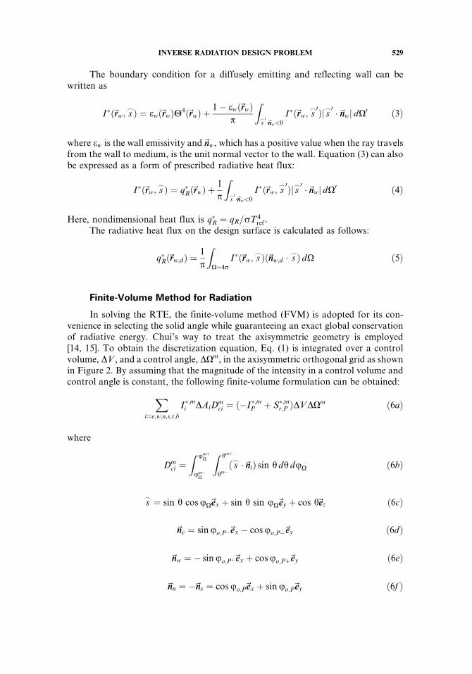
In solving the RTE, the finite-volume method (FVM) is adopted for its con-venience in selecting the solid angle while guaranteeing an exact global conservationof radiative energy. Chui’s way to treat the axisymmetric geometry is employed[14, 15]. To obtain the discretization equation, Eq. (1) is integrated over a controlvolume, DV , and a control angle, DXm, in the axisymmetric orthogonal grid as shownin Figure 2. By assuming that the magnitude of the intensity in a control volume andcontrol angle is constant, the following finite-volume formulation can be obtained:
Xi¼e;w;n;s;t;b
I�;mi DAiDmci ¼ ð�I�;mP þ S�;mr;P ÞDVDXm ð6aÞ
where
Dmci ¼
Z umþX
um�X
Z hmþ
hm�ð s_ �~nniÞ sin h dh duX ð6bÞ
s_ ¼ sin h cos uX~eex þ sin h sin uX~eey þ cos h~eez ð6cÞ
~nne ¼ sin uo;P�~eex � cos uo;P�~eey ð6dÞ
~nnw ¼ � sin uo;Pþ~eex þ cos uo;Pþ~eey ð6eÞ
~nnn ¼ �~nns ¼ cos uo;P~eex þ sin uo;P~eey ð6f Þ
INVERSE RADIATION DESIGN PROBLEM 529
~nnt ¼ �~nnb ¼~eez ð6gÞ
S�;mr ¼ ð1� xoÞH4 þ xo
4p
ZX0¼4p
I�;m0Um0!m dX0 ð6hÞ
DXm ¼Z umþ
X
um�X
Z hmþ
hm�sin h dh duX ð6iÞ
To relate the intensities on the control-volume surfaces to a nodal one, the stepscheme, which is not only simple and convenient but also ensures positive intensity, is
Figure 2. Angular control angle and spatial control volume: (a) angular control angle; (b) spatial control
volume.
530 K. W. KIM AND S. W. BAEK
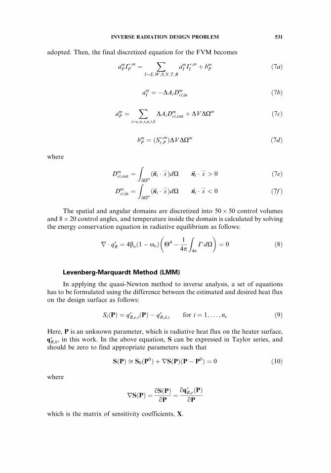
adopted. Then, the final discretized equation for the FVM becomes
amP I�;mP ¼
XI¼E;W ;S;N;T ;B
amI I�;mI þ bm
P ð7aÞ
amI ¼ �DAiD
mci;in ð7bÞ
amP ¼
Xi¼e;w;s;n;t;b
DAiDmci;out þ DVDXm ð7cÞ
bmP ¼ ðS
�;mr;P ÞDVDXm ð7dÞ
where
Dmci;out ¼
ZDXmð~nni � s
_ÞdX ~nni � s_> 0 ð7eÞ
Dmci;in ¼
ZDXmð~nni � s
_ÞdX ~nni � s_< 0 ð7f Þ
The spatial and angular domains are discretized into 50� 50 control volumesand 8� 20 control angles, and temperature inside the domain is calculated by solvingthe energy conservation equation in radiative equilibrium as follows:
r � q�R ¼ 4boð1� xoÞ H4 � 1
4p
Z4p
I�dX
� �¼ 0 ð8Þ
Levenberg-Marquardt Method (LMM)
In applying the quasi-Newton method to inverse analysis, a set of equationshas to be formulated using the difference between the estimated and desired heat fluxon the design surface as follows:
SiðPÞ ¼ q�R;e;iðPÞ � q�R;d;i for i ¼ 1; . . . ; ne ð9Þ
Here, P is an unknown parameter, which is radiative heat flux on the heater surface,q�R;h, in this work. In the above equation, S can be expressed in Taylor series, andshould be zero to find appropriate parameters such that
SðPÞ ffi S0ðP0Þ þ rSðPÞðP� P0Þ ¼ 0 ð10Þ
where
rSðPÞ ¼ qSðPÞqP
¼qq�R;eðPÞ
qP
which is the matrix of sensitivity coefficients, X.
INVERSE RADIATION DESIGN PROBLEM 531
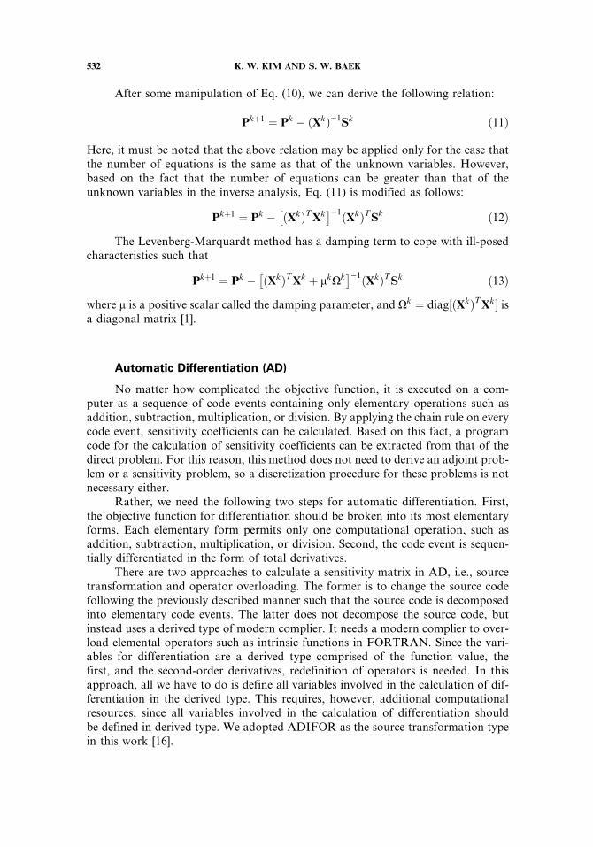
After some manipulation of Eq. (10), we can derive the following relation:
Pkþ1 ¼ Pk � ðXkÞ�1Sk ð11Þ
Here, it must be noted that the above relation may be applied only for the case thatthe number of equations is the same as that of the unknown variables. However,based on the fact that the number of equations can be greater than that of theunknown variables in the inverse analysis, Eq. (11) is modified as follows:
Pkþ1 ¼ Pk ��ðXkÞT Xk
��1ðXkÞT Sk ð12Þ
The Levenberg-Marquardt method has a damping term to cope with ill-posedcharacteristics such that
Pkþ1 ¼ Pk ��ðXkÞT Xk þ mkXk
��1ðXkÞT Sk ð13Þ
where m is a positive scalar called the damping parameter, and Xk ¼ diag½ðXkÞT Xk� isa diagonal matrix [1].
Automatic Differentiation (AD)
No matter how complicated the objective function, it is executed on a com-puter as a sequence of code events containing only elementary operations such asaddition, subtraction, multiplication, or division. By applying the chain rule on everycode event, sensitivity coefficients can be calculated. Based on this fact, a programcode for the calculation of sensitivity coefficients can be extracted from that of thedirect problem. For this reason, this method does not need to derive an adjoint prob-lem or a sensitivity problem, so a discretization procedure for these problems is notnecessary either.
Rather, we need the following two steps for automatic differentiation. First,the objective function for differentiation should be broken into its most elementaryforms. Each elementary form permits only one computational operation, such asaddition, subtraction, multiplication, or division. Second, the code event is sequen-tially differentiated in the form of total derivatives.
There are two approaches to calculate a sensitivity matrix in AD, i.e., sourcetransformation and operator overloading. The former is to change the source codefollowing the previously described manner such that the source code is decomposedinto elementary code events. The latter does not decompose the source code, butinstead uses a derived type of modern complier. It needs a modern complier to over-load elemental operators such as intrinsic functions in FORTRAN. Since the vari-ables for differentiation are a derived type comprised of the function value, thefirst, and the second-order derivatives, redefinition of operators is needed. In thisapproach, all we have to do is define all variables involved in the calculation of dif-ferentiation in the derived type. This requires, however, additional computationalresources, since all variables involved in the calculation of differentiation shouldbe defined in derived type. We adopted ADIFOR as the source transformation typein this work [16].
532 K. W. KIM AND S. W. BAEK
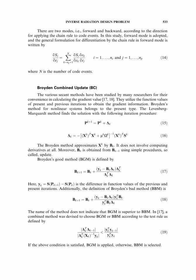
There are two modes, i.e., forward and backward, according to the directionfor applying the chain rule to code events. In this study, forward mode is adopted,and the general formulation for differentiation by the chain rule in forward mode iswritten by
qSi
qej¼
XN
k¼npþ1
qSi
qek
qek
qeji ¼ 1; . . . ; ne and j ¼ 1; . . . ; np ð14Þ
where N is the number of code events.
Broyden Combined Update (BC)
The various secant methods have been studied by many researchers for theirconvenience in calculating the gradient value [17, 18]. They utilize the function valuesof present and previous iterations to obtain the gradient information. Broyden’smethod for nonlinear systems belongs to the present type. The Levenberg-Marquardt method finds the solution with the following iteration procedure:
Pkþ1 ¼ Pk þ Dk ð15Þ
Dk ¼ ��ðXkÞT Xk þ mkXk
��1ðXkÞT Sk ð16Þ
The Broyden method approximates Xk by Bk. It does not involve computingderivatives at all. Moreover, Bk is obtained from Bk�1 using simple procedures, socalled, update.
Broyden’s good method (BGM) is defined by
Bkþ1 ¼ Bk þðyk � BkDkÞDT
k
DTk Dk
ð17Þ
Here, yk ¼ SðPkþ1Þ � SðPkÞ is the difference in function values of the previous andpresent iterations. Additionally, the definition of Broyden’s bad method (BBM) is
Bkþ1 ¼ Bk þðyk � BkDkÞyT
k Bk
yTk BkDk
ð18Þ
The name of the method does not indicate that BGM is superior to BBM. In [17], acombined method was devised to choose BGM or BBM according to the test rule asdefined by
jDTk Dk�1j
jDTk ðXkÞ�1
ykj<jyT
k yk�1jyT
k yk
ð19Þ
If the above condition is satisfied, BGM is applied, otherwise, BBM is selected.
INVERSE RADIATION DESIGN PROBLEM 533
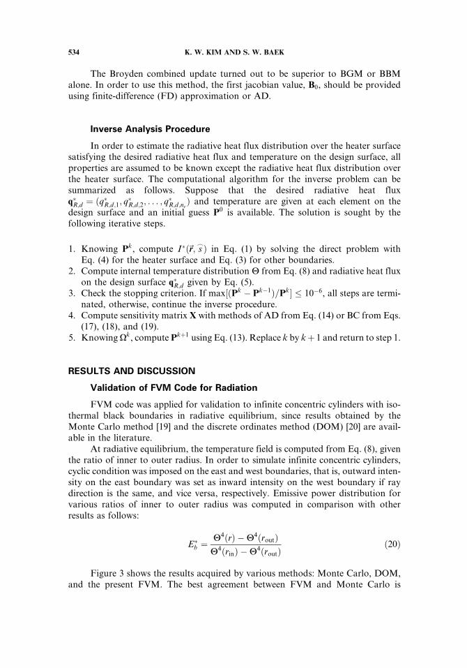
The Broyden combined update turned out to be superior to BGM or BBMalone. In order to use this method, the first jacobian value, B0, should be providedusing finite-difference (FD) approximation or AD.
Inverse Analysis Procedure
In order to estimate the radiative heat flux distribution over the heater surfacesatisfying the desired radiative heat flux and temperature on the design surface, allproperties are assumed to be known except the radiative heat flux distribution overthe heater surface. The computational algorithm for the inverse problem can besummarized as follows. Suppose that the desired radiative heat fluxq�R;d ¼ ðq�R;d;1; q�R;d;2; . . . ; q�R;d;ne
Þ and temperature are given at each element on thedesign surface and an initial guess P0 is available. The solution is sought by thefollowing iterative steps.
1. Knowing Pk, compute I�ð~rr; s_Þ in Eq. (1) by solving the direct problem with
Eq. (4) for the heater surface and Eq. (3) for other boundaries.2. Compute internal temperature distribution H from Eq. (8) and radiative heat flux
on the design surface q�R;d given by Eq. (5).3. Check the stopping criterion. If max½ðPk � Pk�1Þ=Pk� � 10�6, all steps are termi-
nated, otherwise, continue the inverse procedure.4. Compute sensitivity matrix X with methods of AD from Eq. (14) or BC from Eqs.
(17), (18), and (19).5. Knowing Xk, compute Pkþ1 using Eq. (13). Replace k by kþ 1 and return to step 1.
RESULTS AND DISCUSSION
Validation of FVM Code for Radiation
FVM code was applied for validation to infinite concentric cylinders with iso-thermal black boundaries in radiative equilibrium, since results obtained by theMonte Carlo method [19] and the discrete ordinates method (DOM) [20] are avail-able in the literature.
At radiative equilibrium, the temperature field is computed from Eq. (8), giventhe ratio of inner to outer radius. In order to simulate infinite concentric cylinders,cyclic condition was imposed on the east and west boundaries, that is, outward inten-sity on the east boundary was set as inward intensity on the west boundary if raydirection is the same, and vice versa, respectively. Emissive power distribution forvarious ratios of inner to outer radius was computed in comparison with otherresults as follows:
E�b ¼H4ðrÞ �H4ðroutÞH4ðrinÞ �H4ðroutÞ
ð20Þ
Figure 3 shows the results acquired by various methods: Monte Carlo, DOM,and the present FVM. The best agreement between FVM and Monte Carlo is
534 K. W. KIM AND S. W. BAEK
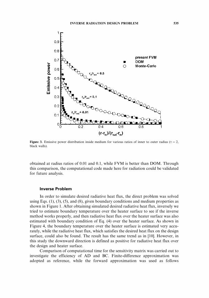
obtained at radius ratios of 0.01 and 0.1, while FVM is better than DOM. Throughthis comparison, the computational code made here for radiation could be validatedfor future analysis.
Inverse Problem
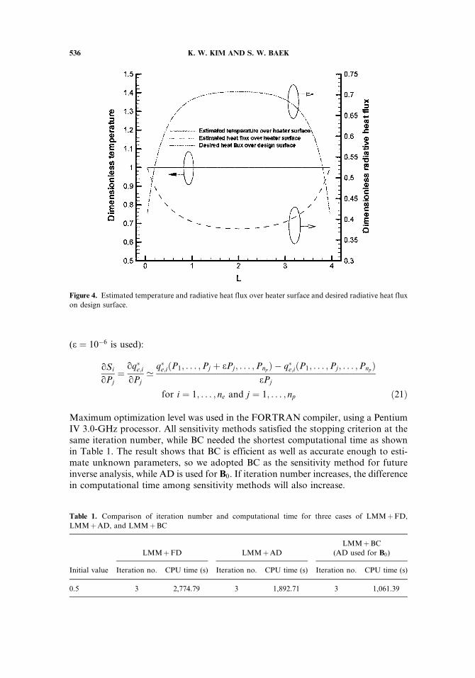
In order to simulate desired radiative heat flux, the direct problem was solvedusing Eqs. (1), (3), (5), and (8), given boundary conditions and medium properties asshown in Figure 1. After obtaining simulated desired radiative heat flux, inversely wetried to estimate boundary temperature over the heater surface to see if the inversemethod works properly, and then radiative heat flux over the heater surface was alsoestimated with boundary condition of Eq. (4) over the heater surface. As shown inFigure 4, the boundary temperature over the heater surface is estimated very accu-rately, while the radiative heat flux, which satisfies the desired heat flux on the designsurface, could also be found. The result has the same trend as in [10]. However, inthis study the downward direction is defined as positive for radiative heat flux overthe design and heater surface.
Comparison of computational time for the sensitivity matrix was carried out toinvestigate the efficiency of AD and BC. Finite-difference approximation wasadopted as reference, while the forward approximation was used as follows
Figure 3. Emissive power distribution inside medium for various ratios of inner to outer radius (s ¼ 2,
black walls).
INVERSE RADIATION DESIGN PROBLEM 535
(e ¼ 10�6 is used):
qSi
qPj¼
qq�e;iqPj’
q�e;iðP1; . . . ;Pj þ ePj; . . . ;PnpÞ � q�e;iðP1; . . . ;Pj; . . . ;Pnp
ÞePj
for i ¼ 1; . . . ; ne and j ¼ 1; . . . ; np ð21Þ
Maximum optimization level was used in the FORTRAN compiler, using a PentiumIV 3.0-GHz processor. All sensitivity methods satisfied the stopping criterion at thesame iteration number, while BC needed the shortest computational time as shownin Table 1. The result shows that BC is efficient as well as accurate enough to esti-mate unknown parameters, so we adopted BC as the sensitivity method for futureinverse analysis, while AD is used for B0. If iteration number increases, the differencein computational time among sensitivity methods will also increase.
Figure 4. Estimated temperature and radiative heat flux over heater surface and desired radiative heat flux
on design surface.
Table 1. Comparison of iteration number and computational time for three cases of LMMþFD,
LMMþAD, and LMMþBC
LMMþFD LMMþAD
LMMþBC
(AD used for B0)
Initial value Iteration no. CPU time (s) Iteration no. CPU time (s) Iteration no. CPU time (s)
0.5 3 2,774.79 3 1,892.71 3 1,061.39
536 K. W. KIM AND S. W. BAEK
Effect of Ratio of Cylinder Length to Outer Radius
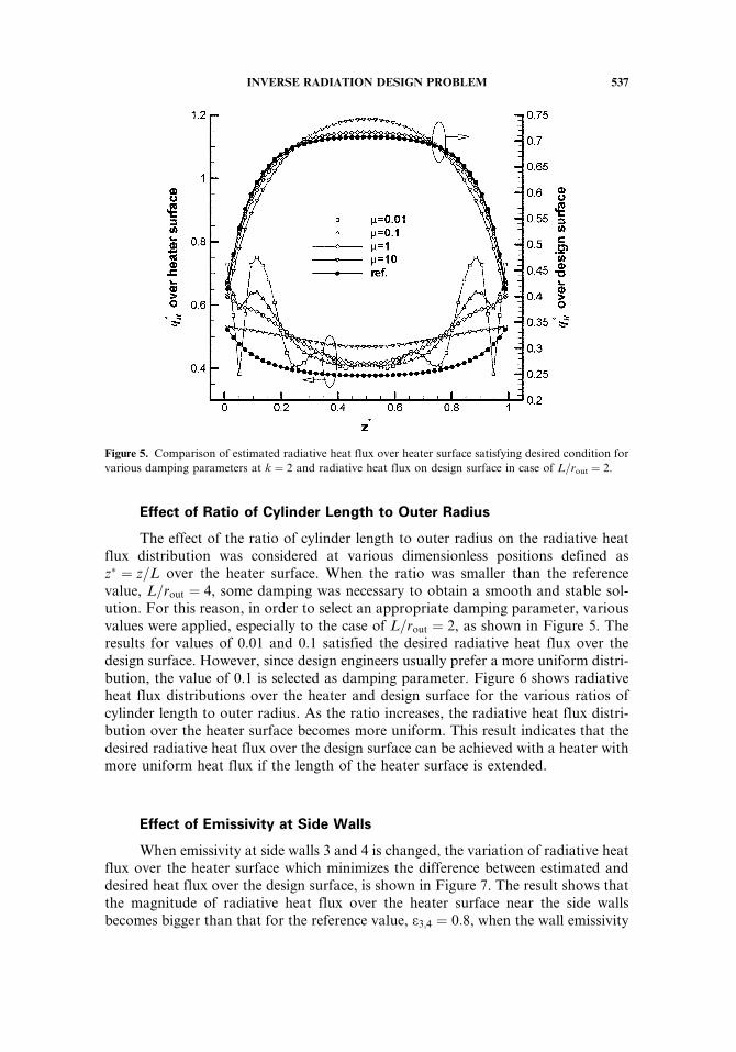
The effect of the ratio of cylinder length to outer radius on the radiative heatflux distribution was considered at various dimensionless positions defined asz� ¼ z=L over the heater surface. When the ratio was smaller than the referencevalue, L=rout ¼ 4, some damping was necessary to obtain a smooth and stable sol-ution. For this reason, in order to select an appropriate damping parameter, variousvalues were applied, especially to the case of L=rout ¼ 2, as shown in Figure 5. Theresults for values of 0.01 and 0.1 satisfied the desired radiative heat flux over thedesign surface. However, since design engineers usually prefer a more uniform distri-bution, the value of 0.1 is selected as damping parameter. Figure 6 shows radiativeheat flux distributions over the heater and design surface for the various ratios ofcylinder length to outer radius. As the ratio increases, the radiative heat flux distri-bution over the heater surface becomes more uniform. This result indicates that thedesired radiative heat flux over the design surface can be achieved with a heater withmore uniform heat flux if the length of the heater surface is extended.
Effect of Emissivity at Side Walls
When emissivity at side walls 3 and 4 is changed, the variation of radiative heatflux over the heater surface which minimizes the difference between estimated anddesired heat flux over the design surface, is shown in Figure 7. The result shows thatthe magnitude of radiative heat flux over the heater surface near the side wallsbecomes bigger than that for the reference value, e3;4 ¼ 0:8, when the wall emissivity
Figure 5. Comparison of estimated radiative heat flux over heater surface satisfying desired condition for
various damping parameters at k ¼ 2 and radiative heat flux on design surface in case of L=rout ¼ 2.
INVERSE RADIATION DESIGN PROBLEM 537
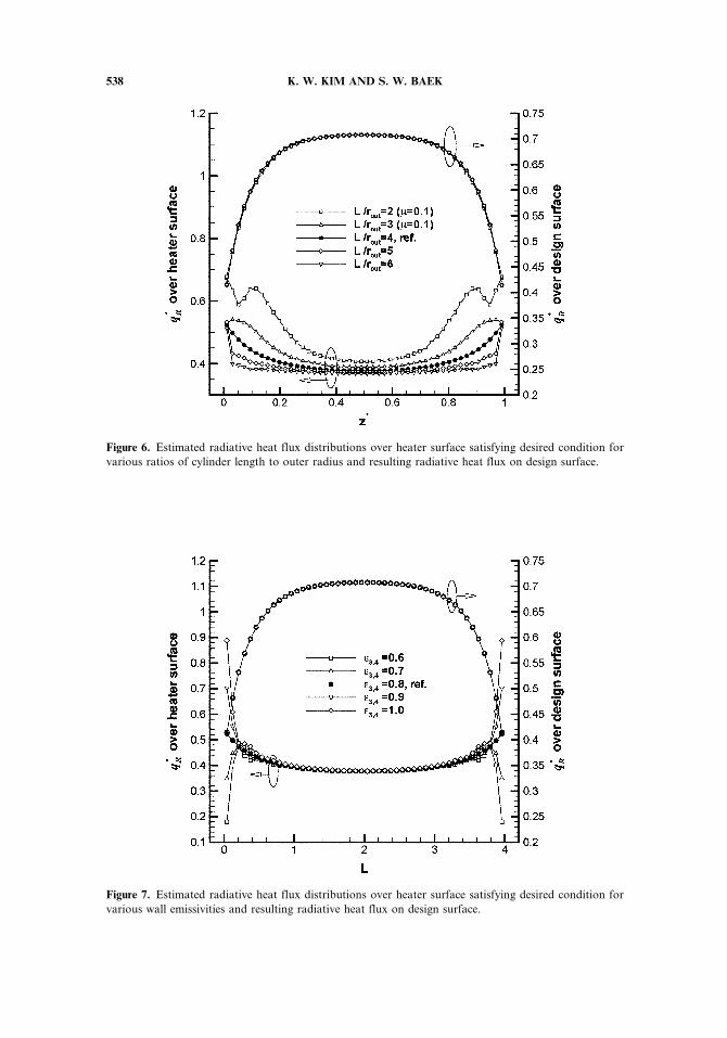
Figure 6. Estimated radiative heat flux distributions over heater surface satisfying desired condition for
various ratios of cylinder length to outer radius and resulting radiative heat flux on design surface.
Figure 7. Estimated radiative heat flux distributions over heater surface satisfying desired condition for
various wall emissivities and resulting radiative heat flux on design surface.
538 K. W. KIM AND S. W. BAEK
increases. Even though the emissivity was significantly changed, correspondinginverse solutions satisfying the desired heat flux were found.
Effect of Temperature at Side Walls
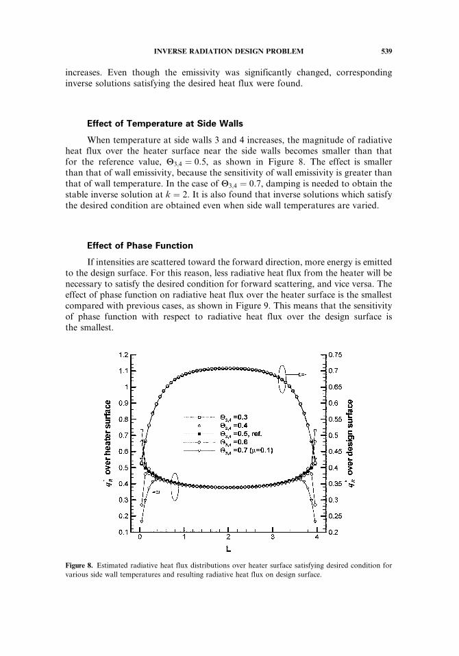
When temperature at side walls 3 and 4 increases, the magnitude of radiativeheat flux over the heater surface near the side walls becomes smaller than thatfor the reference value, H3;4 ¼ 0:5, as shown in Figure 8. The effect is smallerthan that of wall emissivity, because the sensitivity of wall emissivity is greater thanthat of wall temperature. In the case of H3;4 ¼ 0:7, damping is needed to obtain thestable inverse solution at k ¼ 2. It is also found that inverse solutions which satisfythe desired condition are obtained even when side wall temperatures are varied.
Effect of Phase Function
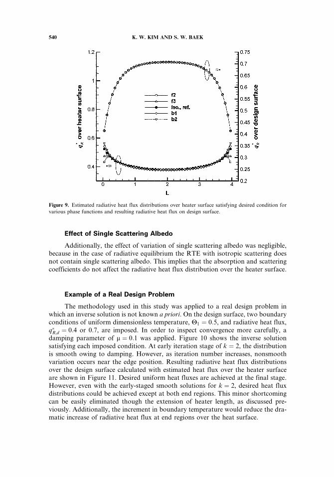
If intensities are scattered toward the forward direction, more energy is emittedto the design surface. For this reason, less radiative heat flux from the heater will benecessary to satisfy the desired condition for forward scattering, and vice versa. Theeffect of phase function on radiative heat flux over the heater surface is the smallestcompared with previous cases, as shown in Figure 9. This means that the sensitivityof phase function with respect to radiative heat flux over the design surface isthe smallest.
Figure 8. Estimated radiative heat flux distributions over heater surface satisfying desired condition for
various side wall temperatures and resulting radiative heat flux on design surface.
INVERSE RADIATION DESIGN PROBLEM 539
Effect of Single Scattering Albedo
Additionally, the effect of variation of single scattering albedo was negligible,because in the case of radiative equilibrium the RTE with isotropic scattering doesnot contain single scattering albedo. This implies that the absorption and scatteringcoefficients do not affect the radiative heat flux distribution over the heater surface.
Example of a Real Design Problem
The methodology used in this study was applied to a real design problem inwhich an inverse solution is not known a priori. On the design surface, two boundaryconditions of uniform dimensionless temperature, H1 ¼ 0:5, and radiative heat flux,q�R;d ¼ 0:4 or 0.7, are imposed. In order to inspect convergence more carefully, adamping parameter of m ¼ 0:1 was applied. Figure 10 shows the inverse solutionsatisfying each imposed condition. At early iteration stage of k ¼ 2, the distributionis smooth owing to damping. However, as iteration number increases, nonsmoothvariation occurs near the edge position. Resulting radiative heat flux distributionsover the design surface calculated with estimated heat flux over the heater surfaceare shown in Figure 11. Desired uniform heat fluxes are achieved at the final stage.However, even with the early-staged smooth solutions for k ¼ 2, desired heat fluxdistributions could be achieved except at both end regions. This minor shortcomingcan be easily eliminated though the extension of heater length, as discussed pre-viously. Additionally, the increment in boundary temperature would reduce the dra-matic increase of radiative heat flux at end regions over the heat surface.
Figure 9. Estimated radiative heat flux distributions over heater surface satisfying desired condition for
various phase functions and resulting radiative heat flux on design surface.
540 K. W. KIM AND S. W. BAEK
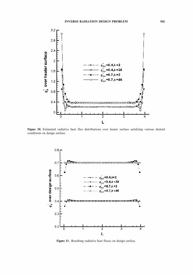
Figure 10. Estimated radiative heat flux distributions over heater surface satisfying various desired
conditions on design surface.
Figure 11. Resulting radiative heat fluxes on design surface.
INVERSE RADIATION DESIGN PROBLEM 541
CONCLUSIONS
Inverse radiation design analysis in a two-dimensional, concentric, cylindrical,absorbing, emitting, and scattering medium has been conducted, given desiredboundary conditions on the design surface. By adopting the automatic differen-tiation and the Broyden combined update as sensitivity method, the computationaltime for calculating the sensitivity matrix could be reduced up to one-third comparedwith that required for the finite-difference approximation.
Various parametric analyses have shown that in most cases the radiative heatflux over the heater surface satisfying the desired condition over the design surfacecould be well estimated using the current inverse analysis. Stable and smoothsolution could be obtained by controlling the damping parameter used in theLevenberg-Marqurdt method, even for ill-posed cases.
Finally, the inverse method was applied to a real design problem to get theradiative heat flux over a heater surface satisfying uniform heat flux and temperaturedistribution on the design surface. Even with the early-staged smooth solutions,the desired heat flux distributions could be achieved except at both end regions.This minor trouble could be successfully eliminated though extension of the heatersurface length.
REFERENCES
1. M. N. Ozisik and H. R. B. Orlande, Inverse Heat Transfer, chap. 1, Taylor & Francis,New York, 2000.
2. H. Y. Li and C. Y. Yang, A Genetic Algorithm for Inverse Radiation Problems, Int. J.Heat Mass Transfer, vol. 40, pp. 1545–1549, 1997.
3. N. R. Ou and C. H. Wu, Simultaneous Estimation of Extinction Coefficient Distribution,Scattering Albedo and Phase Function of a Two-Dimensional Medium, Int. J. Heat MassTransfer, vol. 45, pp. 4663–4674, 2002.
4. H. Y. Li, An Inverse Source Problem in Radiative Transfer for Spherical Media, Numer.Heat Transfer B, vol. 32, pp. 251–260, 1997.
5. H. M. Park and T. Y. Yoon, Solution of the Inverse Radiation Problem Using a Conju-gate Gradient Method, Int. J. Heat Mass Transfer, vol. 43, pp. 1767–1776, 2000.
6. K. W. Kim, S. W. Baek, M. Y. Kim, and H. S. Ryu, Estimation of Emissivities in a Two-Dimensional Irregular Geometry by Inverse Radiation Analysis Using Hybrid GeneticAlgorithm, J. Quant. Spectrosc. Radiat. Transfer, vol. 87, pp. 1–14, 2004.
7. D. K. Alexander and H. H. Andreas, Optical Tomography Using the Time-IndependentEquation of Radiative Transfer—Part 2: Inverse Model, J. Quant. Spectrosc. Radiat.Transfer, vol. 72, pp. 691–713, 2002.
8. M. R. Jones, Inverse Analysis of Radiative Heat Transfer Systems, J. Heat Transfer, vol.121, pp. 481–484, 1999.
9. J. R. Howell, O. A. Ezekoye, and J. C. Morales, Inverse Design Model for Radiative HeatTransfer, J. Heat Transfer, vol. 122, pp. 492–502, 2000.
10. S. S. M. Hosseini, S. H. Mansouri, and J. R. Howell, Inverse Boundary Design RadiationProblem in Absorbing-Emitting Media with Irregular Geometry, Numer. Heat Transfer A,vol. 43, pp. 565–584, 2003.
11. S. S. M. Hosseini and S. H. Mansouri, Inverse Design for Radiative Heat Source inTwo-Dimensional Participating Media, Numer. Heat Transfer B, vol. 46, pp. 283–300,2004.
542 K. W. KIM AND S. W. BAEK
12. K. W. Kim and S. W. Baek, Inverse Surface Radiation Analysis in an Axisymmetric Cyl-indrical Enclosure Using a Hybrid Genetic Algorithm, Numer. Heat Transfer A, vol. 46,pp. 367–381, 2004.
13. K. W. Kim and S. W. Baek, Comparison of Sensitivity Methods for the FunctionEstimation of Boundary Conditions by Inverse Radiation Analysis, 4th InternationalConference on Computational Heat and Mass Transfer, Paris-Cachan, France, vol. 2,pp. 1385–1390, 2005.
14. E. H. Chui, G. D. Raithby, and P. M. J. Hughes, Prediction of Radiative Transfer inCylindrical Enclosure with the Finite Volume Method, J. Thermophys. Heat Transfer,vol. 6, pp. 605–611, 1992.
15. S. W. Baek and M. Y. Kim, Analysis of Radiative Heating of a Rocket Plume Base withthe Finite-Volume Method, Int. J. Heat Mass Transfer, vol. 40, pp. 1501–1508, 1997.
16. C. Bischof, A. Carle, P. Khademi, A. Mauer, and P. Hovland, ADIFOR2.0 User’s Guide(Revision D), Argonne National Lab. Tech. Memo. ANL=MCS-TM-192, and CRPCTech. Rep. CRPC-TR95516-S, Argonne Natl. Lab., Argonne, IL, 1998.
17. J. M. Martınez, Practical Quasi-Newton Methods for Solving Nonlinear Systems, J. Com-put. Appl. Math, vol. 124, pp. 97–121, 2000.
18. J. E. Dennis and R. B. Schnabel, Numerical Methods for Unconstrained Optimization andNonlinear Equations, chap. 8, Prentice-Hall, Englewood Cliffs, NJ, 1983.
19. M. Perlmuttter and J. R. Howell, Radiant Transfer through a Gray Gas Between Concen-tric Cylinders Using Monte Carlo, J. Heat Transfer, vol. 86, pp. 169–179, 1964.
20. R. Vaillon, M. Lallemand, and D. Lemonnier, Radiative Heat Transfer in OrthogonalCurvilinear Coordinates Using the Discrete Ordinates Method, J. Quant. Spectrosc.Radiat. Transfer, vol. 55, pp. 7–17, 1996.
INVERSE RADIATION DESIGN PROBLEM 543

![Technical Datasheet - Veracious Inc · Inverse Characteristics Curve [Over Current IDMT]: Very Inverse Long Inverse Standard Inverse Extremely Inverse α C 0.02 1 2 1 0.14 13.5 80](https://img.pdfslide.us/doc/110x75/60dab49f5dabad678957ab65/technical-datasheet-veracious-inc-inverse-characteristics-curve-over-current.jpg)