Embed Size (px)
Citation preview
ARTICLE
Inverse design and flexible parameterization ofmeta-optics using algorithmic differentiationShane Colburn 1✉ & Arka Majumdar1,2✉
Ultrathin meta-optics offer unmatched, multifunctional control of light. Next-generation
optical technologies, however, demand unprecedented performance. This will likely require
design algorithms surpassing the capability of human intuition. For the adjoint method, this
requires explicitly deriving gradients, which is sometimes challenging for certain photonics
problems. Existing techniques also comprise a patchwork of application-specific algorithms,
each focused in scope and scatterer type. Here, we leverage algorithmic differentiation as
used in artificial neural networks, treating photonic design parameters as trainable weights,
optical sources as inputs, and encapsulating device performance in the loss function. By
solving a complex, degenerate eigenproblem and formulating rigorous coupled-wave analysis
as a computational graph, we support both arbitrary, parameterized scatterers and topology
optimization. With iteration times below the cost of two forward simulations typical of adjoint
methods, we generate multilayer, multifunctional, and aperiodic meta-optics. As an open-
source platform adaptable to other algorithms and problems, we enable fast and flexible
meta-optical design.
https://doi.org/10.1038/s42005-021-00568-6 OPEN
1 Department of Electrical and Computer Engineering, University of Washington, Seattle, WA, USA. 2Department of Physics, University of Washington,Seattle, WA, USA. ✉email: [email protected]; [email protected]
COMMUNICATIONS PHYSICS | (2021) 4:65 | https://doi.org/10.1038/s42005-021-00568-6 | www.nature.com/commsphys 1
1234
5678
90():,;
Metagratings and metasurfaces1–5 have generated sig-nificant interest in recent years, enabling flat optics6–22
for manipulating the phase, amplitude, and polarizationof incident light. These devices comprise arrays ofsubwavelength-spaced scattering elements whose orientation,geometry, or topology can be designed in a spatially varyingmanner to impart a desired functionality1–5,17. Designing meta-surfaces can be challenging, however, as they often present amassive number of degrees of freedom, with millimeter to cen-timeter scale devices often consisting of millions to billions ofindividual scatterers at visible wavelengths. This poses a class ofhigh-dimensional, fabrication-constrained optimization pro-blems, motivating development of algorithms to efficiently tra-verse parameter spaces for realizing fabricable, high-performancedesigns.
Inverse design techniques have attracted considerableattention as a possible solution. Unlike conventional design,where intuition typically guides the process, the goal of inversedesign is for a user to specify the desired performance and thenuse an optimization algorithm to generate a solution. Manyinverse design techniques for integrated photonics23–28 andmetasurfaces29–36 have relied on gradient descent. These gra-dients are typically calculated by the adjoint method37–39,which calculates derivatives with respect to many input vari-ables with only two simulations of a device. In photonicsapplications, this method has treated the electromagneticsproblem in terms of an overlap between input and outputmodes, as this treatment yields an analytical solution to thegradient with respect to the permittivity at each pointover some design volume40,41. While directly point-by-pointoptimizing the permittivity in this manner enables a largedesign space, converged designs often exhibit grayscale per-mittivity or fabrication-infeasible voids and features42. Thisnecessitates spatial filters, thresholding steps, or additionalmerit function terms that can disrupt gradient computation toensure realistic, fabricable designs26,29,43,44. Adjoint-basedshape optimizations also exist, but these approaches aremostly constrained to special geometries, such as spherical orellipsoidal Mie scatterers45,46, by approximating transmissioncoefficient gradients with a polynomial proxy function32,33 orfinite differences35, using the level set method47,48, or expres-sing parameter gradients as a surface integral over the scattererboundaries49. The light–matter interactions of general photo-nic devices, however, can be quite complicated and it is oftenthe case that their performance metrics and design parametersare not well described by an analytical form or proxyfunction50. For example, in rigorous coupled-wave analysis51
(RCWA), the transmission and reflection properties of astructure are functions of a global scattering matrix with ele-ments that depend on the eigenmodes of each layer. Whilederivation of the adjoint fields in RCWA is possible, changingvariables or scatterer geometries entails additional derivationsteps for different cases, requiring extra work for a designerwhen switching parameterizations.
An alternative to this approach is using algorithmicdifferentiation52–54, also known as automaticdifferentiation (AD)55, as a means for applying the adjoint method.In AD, the output of a sequence of calculations is formulated as acomputational graph in which nodes in the graph representmathematical operations and the edges signify the flow of data fromone operation to another. In this way, if each operation’s derivativeis known, then the derivative of the function that the graphrepresents can be exactly determined via the chain rule55. ThoughAD has existed for some time, its use has expanded substantiallywith the explosion of interest from the machine learning commu-nity with the development of artificial neural networks, giving rise
to several widely used AD frameworks (e.g., TensorFlow, PyTorch,Autograd, etc.). The power of this approach is that no direct deri-vation of the state and adjoint equations is necessary, as this ishandled implicitly in the implementation of the function ofinterest52–54. At the same time, AD-based approaches yield fastcalculation of derivatives compared to both finite differences andsymbolic differentiation. We emphasize that while the adjointmethod is conceptually equivalent to AD in that one can explicitlyderive gradients for a given scatterer parameterization, this processrequires a designer to be familiar with such calculations if evaluatingmultiple scatterer types with varied gradient formulations. Fur-thermore, for many meta-optics problems, it is often unclear apriori what scatterer type is optimal, making AD a flexible tech-nique applicable to general scatterers, enabling not only topologyoptimization but also general shape optimizations without requiringadditional derivation steps. For example, an AD implementation ofthe finite-difference time-domain (FDTD) method was reported56,enabling simulation of general photonic structures; however, thereported implementation is limited to problems with a smallnumber of design variables in order to mitigate excessive compu-tation times. Likewise, an AD implementation of the finite-difference frequency-domain (FDFD) method57 has also been rea-lized. In meta-optics design, however, RCWA is a standard methodfor scatterer optimization owing to its speed benefits and inherentperiodic nature. For RCWA though, using AD for general scatterersor parameterized shapes would pose a complex-valued, degenerateeigenproblem39 that is not typically differentiable58–60 and requiresperturbation theory. Though efficient AD implementations of theplanewave expansion and guided-mode expansion methods wererecently shown50 with impressive results, these were restricted tohandling nondegenerate eigenvalues.
In this paper, we report a generalization of existing eigende-composition gradients to matrices with complex, degenerateeigenvalues by approximating the gradient with regularization,enabling our development of an AD implementation of RCWAusing TensorFlow. We apply our developed framework to theinverse design of metagratings and metasurfaces using bothtopology optimization and parameterized scatterer shapes. Weinverse design devices with responses multiplexed by wavelength,wavevector, and polarization. Leveraging the efficiency of back-propagation, we achieve accelerated gradient calculation55 com-pared to iteration times typically encountered when using theadjoint method. Our developed method could empower designersto flexibly parameterize scatterers and realize next-generationphotonic components.
ResultsGeneralizing eigenproblem gradients. AD has two fundamentaloperating modes for executing its chain rule-based gradientcalculation, known as the forward and reverse modes52,55. Tofind the gradient of the output in forward mode, the derivativesof inner functions are substituted first, which consists ofstarting at the input nodes and moving forward towards theoutput while accumulating the products of each operation’sderivative. Reverse mode works backwards, substituting theouter functions first, and traversing a path from the output backto the input. While both modes yield the same result, when thenumber of inputs is large compared to the number of outputs,reverse mode is far more efficient52,55. As such, we use reversemode since we compute a single output scalar (our loss func-tion) from at least one and potentially a multitude of inputvariables characterizing our unit cell(s). Leveraging AD, how-ever, also requires all the operations in our calculation to bedifferentiable. Most of the calculations required for RCWA arestandard operations with well-known derivatives that are
ARTICLE COMMUNICATIONS PHYSICS | https://doi.org/10.1038/s42005-021-00568-6
2 COMMUNICATIONS PHYSICS | (2021) 4:65 | https://doi.org/10.1038/s42005-021-00568-6 | www.nature.com/commsphys
readily implemented as part of an AD framework. At the heartof RCWA, however, is the solving of Fourier domain Maxwell’sequations per layer, composed as the eigenequation61
d2
d~z2sxsy
" #¼ Ω2
sxsy
" #; ð1Þ
where sx and sy are the Fourier coefficients of the x and ycomponents of the electric field, ~z ¼ k0z is the normalized zcoordinate along the layer thickness direction, and Ω2 is a blockmatrix that is a function of both the wavevector expansions andthe layer’s permittivity and permeability. As we apply sub-sequent operations to the resultant eigendecomposition toultimately calculate transmission and reflection coefficients, weneed the derivatives of the eigenvectors and eigenvalues tomaintain the backpropagation chain for gradients. For Her-mitian matrices with nondegenerate eigenvalues, these deriva-tives exist62; however, computing eigendecomposition gradientsbecomes more complicated for non-Hermitian matrices as theyhave complex eigenvalues. Furthermore, eigenvector gradientsare actually undefined in reverse mode if there are any degen-erate eigenvalues58–60. Although workarounds do exist in for-ward mode58, these would have us lose the efficiency benefits ofreverse mode. These challenges preclude an exact, AD imple-mentation of RCWA in reverse mode because while somespecial case scatterers present an eigenequation with distincteigenvalues, this is not the case for general scatterer shapes andtopologies.
To formulate a reverse mode RCWA implementation applic-able to general scatterers, we bring together two separateinnovations: generalization of the existing eigendecompositiongradient computation in TensorFlow to complex eigenvalues, andsecondly a regularization scheme for approximating the reversemode gradient for degenerate eigenvalues. The first of theseinnovations was previously implemented for an acousticbeamforming application63, whereas regularization techniquesfor degenerate eigenvalues have been proposed separately59,60. Tothe best of our knowledge, however, these two methods have notbeen simultaneously applied for general eigendecompositiongradients. To aid understanding, we include here a portion ofthe math underpinning these two separate techniques developedin prior works60,63. Assume we have an eigenequation of the form
ΦW ¼ WΛ; ð2Þwhere the columns of W are the eigenvectors of Φ and Λ is thediagonal matrix of eigenvalues. If we have a real output scalarfunction, J= f(W,Λ), that depends on this eigendecomposition,then when Λ is real, the reverse mode sensitivity is62
∂J∂Φ
¼ W�T ∂J∂Λ
þ F � WT ∂J∂W
� �� �WT; ð3Þ
where ◦ denotes the Hadamard product, Fij= 1/(λi−λj) if i ≠ j andFii= 0, and the λi’s are the eigenvalues. This is also the gradientprovided by TensorFlow’s linalg.eigh() function, which handlesHermitian matrices as this ensures the eigenvalues are all real. Tohandle complex eigenvalues, however, we need to define a complexderivative using Wirtinger calculus, which provides similar behaviorto that of ordinary derivatives of real functions but for differentiablefunctions on a complex domain. If we assume the output scalar J isreal but still depends on the eigendecomposition when we havecomplex Λ, we can instead differentiate with respect toΦ* using theWirtinger derivative. This yields
∂J
∂Φ*¼ W�H ∂J
∂Λ*þ F* � WH ∂J
∂W*
� �� �WH; ð4Þ
as derived previously63. In both the real and complex versions, if
there are any degenerate eigenvalues, then both F and the gradientare undefined. To circumvent this, we utilize a regularizationscheme leveraged previously60, applying a Lorentzian broadeningwhere we instead set
Fij ¼λi � λj
λi � λj
� �2þ ε
; ð5Þ
with ε being a small real number, a hyperparameter that produces asmall error in Fij but regularizes our gradient calculation forcomplex, degenerate eigenvalues. We select ε by adjusting its valueto minimize the gradient error compared to a finite differencecalculation (see Supplementary Note 1 and Fig. S1).
Inverse design framework. With a reverse mode implementationof general eigendecomposition, we can now construct an end-to-end differentiable RCWA inverse design framework using AD.Our approach is shown schematically in Fig. 1. The key aspects ofthe framework are the hyperparameters and optimization vari-ables, the RCWA implementation itself, the input excitationsorganized as a batch tensor, and the loss function (i.e., the figureof merit) to optimize. The hyperparameters define the systemunder consideration and form the base tensor that represents theshape of our network through which data will flow (e.g., howmany real space points are used to represent the permittivity, howmany dielectric layers our structure has, etc.). The optimizationvariables depend on the unit cell parameterization or topology.While our framework enables the permittivity to vary freelywithin each unit cell, we can just as easily define a shape opti-mization with respect to the geometric parameters of a scatter.This includes optimizing the diameter and thickness of a con-ventional, nanopost-based grating or metasurface without havingto derive any complicated state and adjoint equations that dependupon the variable selection. With a given parameterization, wecan then calculate the permittivity of our unit cell and feed thatunit cell into the RCWA model. The RCWA implementationcomprises the core of the framework, modeling the physics of theunit cell in a forward pass. This includes generating convolutionmatrices, solving the Fourier domain eigenequation for the modesin each layer of the structure, finding the global scattering matrixvia a Redheffer star product of the individual layer scatteringmatrices, and extracting the transmission and reflection coeffi-cients for the unit cell(s). This yields a black box defining aninput-output relationship for a given structure. Then, for a batchof input excitations (e.g., for varying wavelength, polarization, orwavevector) that feed into our tensor network, we determine thestate of the output light when it is incident on the unit cell(s).Finally, this output is passed into a scalar loss function, whichcould simply be the reflectance or transmittance, or more com-plicated metrics based on responses multiplexed by the input asdesired by the user. Alternatively, our tensor network couldconstitute an array of many unit cells as part of a full metasurface(Fig. 1), and the loss function could be based on properties of thediffracted wavefront, such as maximizing the field magnitude at asingle point for a lens.
Benchmarking. To benchmark our framework, we first evaluatethe accuracy of our gradient calculation as this is critical in itsability to perform optimizations. For this purpose, we consider aperiodic grating of 633 nm tall TiO2 cylinders on an SiO2 sub-strate illuminated with 633 nm light as a model system andcompute the partial derivative of the reflectance with respect tothe duty cycle (i.e., diameter normalized by a grating pitch of 443nm) using our AD technique and compare this to that found bythe finite difference method (Fig. 2a). The gradient computed by
COMMUNICATIONS PHYSICS | https://doi.org/10.1038/s42005-021-00568-6 ARTICLE
COMMUNICATIONS PHYSICS | (2021) 4:65 | https://doi.org/10.1038/s42005-021-00568-6 | www.nature.com/commsphys 3
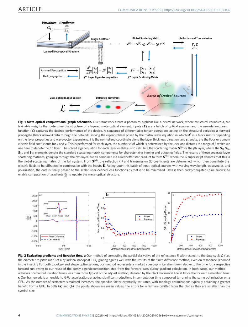
Fig. 2 Evaluating gradients and iteration time. a Our method of computing the partial derivative of the reflectance R with respect to the duty cycle D (i.e.,the diameter to pitch ratio) of a cylindrical nanopost TiO2 grating agrees well with the results of the finite difference method, even on resonance (zoomedin the inset). b For both topology and shape optimizations, our method represents a marked speedup in iteration time relative to the time for a respectiveforward run owing to our reuse of the costly eigendecomposition step from the forward pass during gradient calculation. In both cases, our methodachieves normalized iteration times less than those typical of the adjoint method, denoted by the black horizontal line at twice the forward simulation time.c Our framework is amenable to GPU acceleration, enabling significant reductions in computation time compared to running the same optimization on aCPU. As the number of scatterers simulated increases, the speedup factor eventually saturates, with topology optimizations typically obtaining a greaterbenefit from a GPU. In both (a) and (b), the points shown are mean values, the errors for which are omitted from the plot as they are smaller than thesymbol size.
Fig. 1 Meta-optical computational graph schematic. Our framework treats a photonics problem like a neural network, where structural variables ai aretrainable weights that determine the structure of a layered meta-optical element, inputs ðE
*
Þ are a batch of optical sources, and the user-defined lossfunction Lð Þ captures the desired performance of the device. A sequence of differentiable tensor operations acting on the structural variables ai forwardpropagate (black arrows) data through the network, solving the eigenproblem posed by the matrix wave equation in which Ω2 is a block matrix dependingon the layer properties and wavevector expansions, ~z is the normalized coordinate along the layer thickness direction, and sx and sy are the Fourier domainelectric field coefficients for x and y. This is performed for each layer, the number N of which is determined by the user and dictates the range of j, which weuse here to denote the jth layer. The solved eigenequation for each layer enables us to calculate the scattering matrix S(j) for the jth layer, where the S11, S12,S21, and S22 elements denote the standard scattering matrix components for characterizing ingoing and outgoing fields. The results of these separate layerscattering matrices, going up through the Nth layer, are all combined via a Redheffer star product to form S(G), where the G superscript denotes that this isthe global scattering matrix of the full system. From S(G), the reflection (r) and transmission (t) coefficients are determined, which then constitute theelectric fields to be diffracted in combination with the inputs E
*
. Acting upon this batch of input optical sources with varying wavelength, wavevector, andpolarization, the data is finally passed to the scalar, user-defined loss function Lð Þ that is to be minimized. Data is then backpropagated (blue arrows) toenable computation of gradients ∂L
∂aito update the meta-optical structure.
ARTICLE COMMUNICATIONS PHYSICS | https://doi.org/10.1038/s42005-021-00568-6
4 COMMUNICATIONS PHYSICS | (2021) 4:65 | https://doi.org/10.1038/s42005-021-00568-6 | www.nature.com/commsphys

our technique agrees well with that from the finite differenceapproximation, even on resonance (Fig. 2a inset). The meanfractional error for the computed gradient in this model systemwas 0.56%, demonstrating how closely our method agrees withthe true gradient and validating the accuracy of our approach (seeSupplementary Note 1 and Fig. S1). The validity of the underlyingRCWA solver itself was also evaluated, which was found to be instrong agreement with results produced by the commonly used S4package64 (see Supplementary Notes 2 and 3 and Figs. S2 and S3).
To assess the computational cost, we consider the time peroptimization iteration, as this is the most significant contributor tothe total time for adjoint methods. For the adjoint method, eachiteration usually costs twice the forward simulation time, as bothforward and adjoint simulations are conducted to determine thegradient. In the worst case, the discrete adjoint method would costsix times the forward simulation time per iteration, an upperbound provided by a theoretical result52,54,65 that backpropagationcannot exceed five times the cost of a forward run. In practice,however, AD methods often determine gradients at a smallmultiple of the cost of forward simulation55. Our frameworkperformed far better than this worst case (Fig. 2b), and as thenumber of optimization variables increases with the number ofmetasurface scatterers, we achieved average iteration times as lowas 1.24 times the forward simulation time, 38% less than the typicaltime of two forward simulations for adjoint methods. Thisreduction in relative iteration time compared to the adjointmethod is not possible for all functions but is achievable in our caseby reusing the pre-computed eigenvectors and eigenvalues fromthe forward pass. As the most time-consuming RCWA computa-tion is the eigendecomposition step and as the correspondinggradients depend on these values, storing the results as is requiredfor reverse mode, provides a significant speedup. The absolute timeper iteration depends on the designer’s hardware but as ourmethod is implemented in TensorFlow, a standard deep learningplatform, the computation is highly amenable to acceleration usinggraphics processing units (GPUs), tensor processing units (TPUs),or other dedicated hardware. Figure 2c shows the speedup factorwhen the same optimization is performed using a GPU comparedwith a CPU, demonstrating 14× and 24× speedups for the testedshape and topology optimizations, respectively.
Single-layer metagratings. One of the key benefits of ourapproach is the flexibility it offers in terms of unit cell structure.To demonstrate this, we applied our method to the inverse designof high-performance, single layer metagratings based on variousunit cell types. We first consider a frequently encountered unit cellcomprising a cylinder of TiO2 on an SiO2 substrate (Fig. 3a), thedimensions of which we want to adjust to optimize the reflectanceat discrete wavelengths. With only the cylinder diameter as a freevariable, at an excitation wavelength of 633 nm, we maximize thereflectivity to more than 99.8% compared to an initial value of62.7%. The learning curve in Fig. 3a exhibits minor, decayingoscillations as the reflectivity approaches convergence, arisingfrom successive hopping about the locally optimal diameter.Physically, the change from the initial to final grating design dutycycle manifests as a blueshift (Fig. 3b). Without explicitly derivingany gradients, we can change variables to support alternative unitcell parameterizations, enabling inverse design of a high extinctionratio (22 dB) polarizer based on rectangular scatterers (Fig. 3c, d),as well as a topology-optimized, silicon metagrating that deflects1550 nm light to 75° with absolute and relative efficiencies of 77%and 95%, respectively (Fig. 3e, f).
Multilayer devices. While flat optics based on single layermetagratings have a broad range of applications, they have a
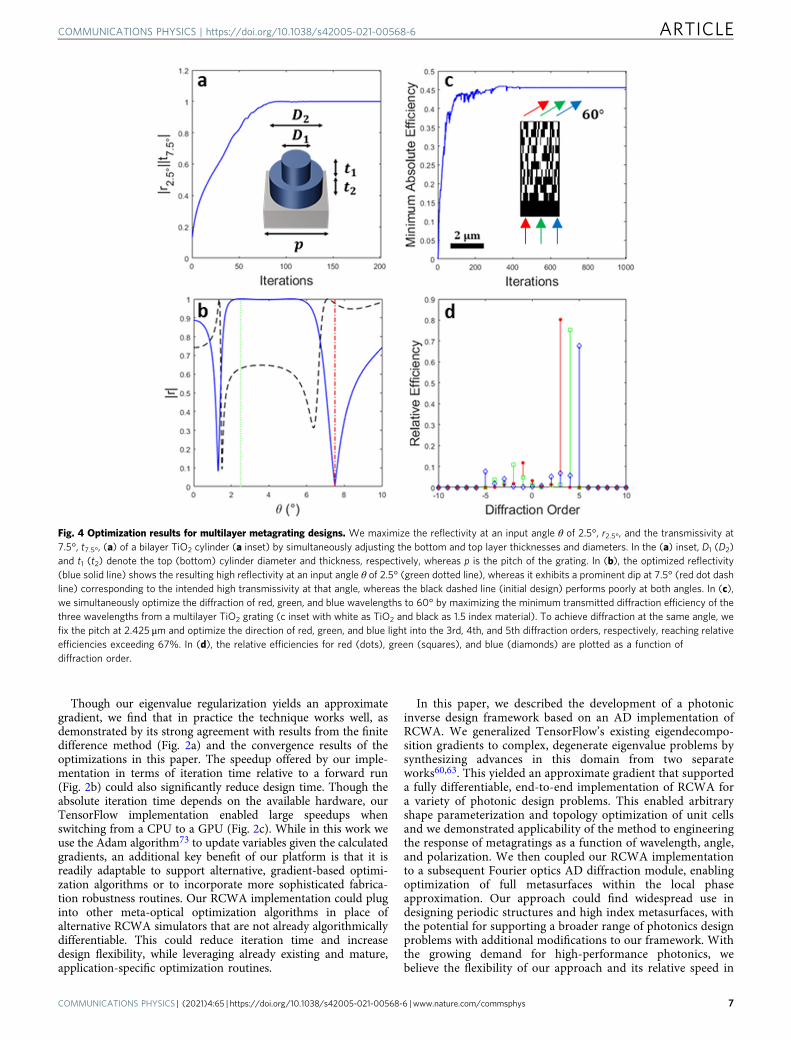
limited number of degrees of freedom. Multilayer devices canincrease the degrees of freedom and exploit mutual interactionsand coupling amongst modes in stacked layers, potentiallyenhancing the desired performance. As RCWA is intended forsuch design problems, our approach lends itself well to multilayerdevices, allowing a designer to select at will the number of unitcell layers in addition to their topology or scatterer shape. We firstdemonstrate this for shape-optimized, bilayer TiO2 cylinders(Fig. 4a) whose reflected power is multiplexed by the light’sincident angle. By optimizing with respect to the cylinder thick-nesses and diameters in the stacked layers, the converged designachieved high-efficiency reflection of 633 nm light at 2.5° whileletting it pass through unattenuated at 7.5° (Fig. 4b).
The same multilayer capability is also extendable to stacked,topology-optimized metagratings. Here, we consider layers of TiO2
with interstitial 1.5 refractive index material (e.g., filled with SiO2 ora polymer). By optimizing each layer’s transverse permittivity profile,we inverse design a 10-layer, volumetric grating that simultaneouslydeflects red (700 nm), green (525 nm), and blue (420 nm) light to60° with high efficiency. We achieve this by performing a maximinoptimization over the three wavelengths to uniformly boost theirdiffraction efficiencies and by selecting a 2.425 μm pitch that enablesus to select separate diffraction orders for each wavelength thatcoincide with the same deflection angle. With each wavelengthachieving a minimum of 45% absolute efficiency and relativeefficiencies all more than 67%, this approach could find applicationsin augmented reality waveguides, where RGB light must besimultaneously deflected at large angles exceeding the critical angle.
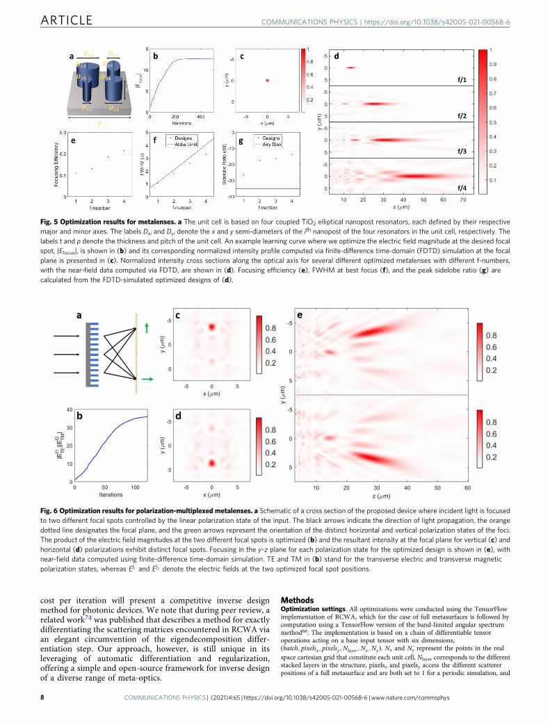
Full metasurfaces. In addition to optimizing the unit cell ofperiodic gratings, our method supports full metasurface opti-mizations wherein arrays of scatterers may impart spatiallyvarying transformations on wavefronts. The applicability of ourmethod to these devices is based on the local phase approx-imation, in which the slow variation of scatterers with positionallows us to approximate each scatterer with the response of onepositioned in a periodic lattice. This enables us to capture theessence of each scatterer with the RCWA-computed transmis-sion and reflection coefficients. By coupling our differentiableRCWA module to an AD-based implementation of the band-limited angular spectrum method66, we form a full pipeline inwhich we can optimize electric fields diffracted by a spatiallyvarying metasurface with respect to an arbitrary parameteriza-tion for our unit cells. Here, we define a shape optimizationbased on a unit cell comprising four coupled elliptical TiO2
nanoposts on an SiO2 substrate (Fig. 5a), with each nanopostcharacterized by their respective major and minor axes. This unitcell selection offers multiple degrees of freedom (8 per unit cell)that can mitigate possible convergence to poor local optima andenables asymmetric scatterer designs that can support polariza-tion discrimination.
We first demonstrate the inverse design of monochromaticlenses at 633 nm for normal incidence. We maximize the electricfield magnitude at a single point on the optical axis correspondingto the desired focal length for designs over a range of different f-number values. Figures 5b and c show the learning curve andoptimized intensity profile at focus for a designed f/1 lens, whileFig. 5d shows intensity profiles along the optical axis for severaldifferent f-number designs, demonstrating convergence over awide range of focal lengths. As our optimization is local and wemust contend with the accuracy limitations of the local phaseapproximation, the intensity profiles of Fig. 5d computed usingFDTD indicate that even for an optimized design, a nonnegligibleportion of light can still be directed to locations away from focus,sometimes including secondary and tertiary focal spots67,68.
COMMUNICATIONS PHYSICS | https://doi.org/10.1038/s42005-021-00568-6 ARTICLE
COMMUNICATIONS PHYSICS | (2021) 4:65 | https://doi.org/10.1038/s42005-021-00568-6 | www.nature.com/commsphys 5
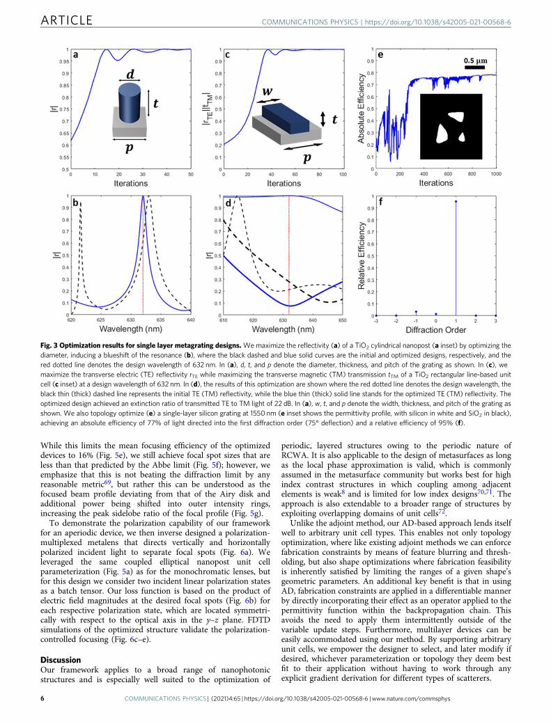
While this limits the mean focusing efficiency of the optimizeddevices to 16% (Fig. 5e), we still achieve focal spot sizes that areless than that predicted by the Abbe limit (Fig. 5f); however, weemphasize that this is not beating the diffraction limit by anyreasonable metric69, but rather this can be understood as thefocused beam profile deviating from that of the Airy disk andadditional power being shifted into outer intensity rings,increasing the peak sidelobe ratio of the focal profile (Fig. 5g).
To demonstrate the polarization capability of our frameworkfor an aperiodic device, we then inverse designed a polarization-multiplexed metalens that directs vertically and horizontallypolarized incident light to separate focal spots (Fig. 6a). Weleveraged the same coupled elliptical nanopost unit cellparameterization (Fig. 5a) as for the monochromatic lenses, butfor this design we consider two incident linear polarization statesas a batch tensor. Our loss function is based on the product ofelectric field magnitudes at the desired focal spots (Fig. 6b) foreach respective polarization state, which are located symmetri-cally with respect to the optical axis in the y–z plane. FDTDsimulations of the optimized structure validate the polarization-controlled focusing (Fig. 6c–e).
DiscussionOur framework applies to a broad range of nanophotonicstructures and is especially well suited to the optimization of
periodic, layered structures owing to the periodic nature ofRCWA. It is also applicable to the design of metasurfaces as longas the local phase approximation is valid, which is commonlyassumed in the metasurface community but works best for highindex contrast structures in which coupling among adjacentelements is weak8 and is limited for low index designs70,71. Theapproach is also extendable to a broader range of structures byexploiting overlapping domains of unit cells72.
Unlike the adjoint method, our AD-based approach lends itselfwell to arbitrary unit cell types. This enables not only topologyoptimization, where like existing adjoint methods we can enforcefabrication constraints by means of feature blurring and thresh-olding, but also shape optimizations where fabrication feasibilityis inherently satisfied by limiting the ranges of a given shape’sgeometric parameters. An additional key benefit is that in usingAD, fabrication constraints are applied in a differentiable mannerby directly incorporating their effect as an operator applied to thepermittivity function within the backpropagation chain. Thisavoids the need to apply them intermittently outside of thevariable update steps. Furthermore, multilayer devices can beeasily accommodated using our method. By supporting arbitraryunit cells, we empower the designer to select, and later modify ifdesired, whichever parameterization or topology they deem bestfit to their application without having to work through anyexplicit gradient derivation for different types of scatterers.
Fig. 3 Optimization results for single layer metagrating designs.Wemaximize the reflectivity (a) of a TiO2 cylindrical nanopost (a inset) by optimizing thediameter, inducing a blueshift of the resonance (b), where the black dashed and blue solid curves are the initial and optimized designs, respectively, and thered dotted line denotes the design wavelength of 632 nm. In (a), d, t, and p denote the diameter, thickness, and pitch of the grating as shown. In (c), wemaximize the transverse electric (TE) reflectivity rTE while maximizing the transverse magnetic (TM) transmission tTM of a TiO2 rectangular line-based unitcell (c inset) at a design wavelength of 632 nm. In (d), the results of this optimization are shown where the red dotted line denotes the design wavelength, theblack thin (thick) dashed line represents the initial TE (TM) reflectivity, while the blue thin (thick) solid line stands for the optimized TE (TM) reflectivity. Theoptimized design achieved an extinction ratio of transmitted TE to TM light of 22 dB. In (a), w, t, and p denote the width, thickness, and pitch of the grating asshown. We also topology optimize (e) a single-layer silicon grating at 1550 nm (e inset shows the permittivity profile, with silicon in white and SiO2 in black),achieving an absolute efficiency of 77% of light directed into the first diffraction order (75° deflection) and a relative efficiency of 95% (f).
ARTICLE COMMUNICATIONS PHYSICS | https://doi.org/10.1038/s42005-021-00568-6
6 COMMUNICATIONS PHYSICS | (2021) 4:65 | https://doi.org/10.1038/s42005-021-00568-6 | www.nature.com/commsphys
Though our eigenvalue regularization yields an approximategradient, we find that in practice the technique works well, asdemonstrated by its strong agreement with results from the finitedifference method (Fig. 2a) and the convergence results of theoptimizations in this paper. The speedup offered by our imple-mentation in terms of iteration time relative to a forward run(Fig. 2b) could also significantly reduce design time. Though theabsolute iteration time depends on the available hardware, ourTensorFlow implementation enabled large speedups whenswitching from a CPU to a GPU (Fig. 2c). While in this work weuse the Adam algorithm73 to update variables given the calculatedgradients, an additional key benefit of our platform is that it isreadily adaptable to support alternative, gradient-based optimi-zation algorithms or to incorporate more sophisticated fabrica-tion robustness routines. Our RCWA implementation could pluginto other meta-optical optimization algorithms in place ofalternative RCWA simulators that are not already algorithmicallydifferentiable. This could reduce iteration time and increasedesign flexibility, while leveraging already existing and mature,application-specific optimization routines.
In this paper, we described the development of a photonicinverse design framework based on an AD implementation ofRCWA. We generalized TensorFlow’s existing eigendecompo-sition gradients to complex, degenerate eigenvalue problems bysynthesizing advances in this domain from two separateworks60,63. This yielded an approximate gradient that supporteda fully differentiable, end-to-end implementation of RCWA fora variety of photonic design problems. This enabled arbitraryshape parameterization and topology optimization of unit cellsand we demonstrated applicability of the method to engineeringthe response of metagratings as a function of wavelength, angle,and polarization. We then coupled our RCWA implementationto a subsequent Fourier optics AD diffraction module, enablingoptimization of full metasurfaces within the local phaseapproximation. Our approach could find widespread use indesigning periodic structures and high index metasurfaces, withthe potential for supporting a broader range of photonics designproblems with additional modifications to our framework. Withthe growing demand for high-performance photonics, webelieve the flexibility of our approach and its relative speed in
Fig. 4 Optimization results for multilayer metagrating designs. We maximize the reflectivity at an input angle θ of 2.5°, r2.5°, and the transmissivity at7.5°, t7.5°, (a) of a bilayer TiO2 cylinder (a inset) by simultaneously adjusting the bottom and top layer thicknesses and diameters. In the (a) inset, D1 (D2)and t1 (t2) denote the top (bottom) cylinder diameter and thickness, respectively, whereas p is the pitch of the grating. In (b), the optimized reflectivity(blue solid line) shows the resulting high reflectivity at an input angle θ of 2.5° (green dotted line), whereas it exhibits a prominent dip at 7.5° (red dot dashline) corresponding to the intended high transmissivity at that angle, whereas the black dashed line (initial design) performs poorly at both angles. In (c),we simultaneously optimize the diffraction of red, green, and blue wavelengths to 60° by maximizing the minimum transmitted diffraction efficiency of thethree wavelengths from a multilayer TiO2 grating (c inset with white as TiO2 and black as 1.5 index material). To achieve diffraction at the same angle, wefix the pitch at 2.425 μm and optimize the direction of red, green, and blue light into the 3rd, 4th, and 5th diffraction orders, respectively, reaching relativeefficiencies exceeding 67%. In (d), the relative efficiencies for red (dots), green (squares), and blue (diamonds) are plotted as a function ofdiffraction order.
COMMUNICATIONS PHYSICS | https://doi.org/10.1038/s42005-021-00568-6 ARTICLE
COMMUNICATIONS PHYSICS | (2021) 4:65 | https://doi.org/10.1038/s42005-021-00568-6 | www.nature.com/commsphys 7
cost per iteration will present a competitive inverse designmethod for photonic devices. We note that during peer review, arelated work74 was published that describes a method for exactlydifferentiating the scattering matrices encountered in RCWA viaan elegant circumvention of the eigendecomposition differ-entiation step. Our approach, however, is still unique in itsleveraging of automatic differentiation and regularization,offering a simple and open-source framework for inverse designof a diverse range of meta-optics.
MethodsOptimization settings. All optimizations were conducted using the TensorFlowimplementation of RCWA, which for the case of full metasurfaces is followed bycomputation using a TensorFlow version of the band-limited angular spectrummethod66. The implementation is based on a chain of differentiable tensoroperations acting on a base input tensor with six dimensions,ðbatch; pixelsx ; pixelsy ;Nlayer ;Nx ;NyÞ. Nx and Ny represent the points in the realspace cartesian grid that constitute each unit cell, Nlayer corresponds to the differentstacked layers in the structure, pixelsx and pixelsy access the different scattererpositions of a full metasurface and are both set to 1 for a periodic simulation, and
Fig. 6 Optimization results for polarization-multiplexed metalenses. a Schematic of a cross section of the proposed device where incident light is focusedto two different focal spots controlled by the linear polarization state of the input. The black arrows indicate the direction of light propagation, the orangedotted line designates the focal plane, and the green arrows represent the orientation of the distinct horizontal and vertical polarization states of the foci.The product of the electric field magnitudes at the two different focal spots is optimized (b) and the resultant intensity at the focal plane for vertical (c) andhorizontal (d) polarizations exhibit distinct focal spots. Focusing in the y–z plane for each polarization state for the optimized design is shown in (e), withnear-field data computed using finite-difference time-domain simulation. TE and TM in (b) stand for the transverse electric and transverse magneticpolarization states, whereas Ef1 and Ef2 denote the electric fields at the two optimized focal spot positions.
Fig. 5 Optimization results for metalenses. a The unit cell is based on four coupled TiO2 elliptical nanopost resonators, each defined by their respectivemajor and minor axes. The labels Dxi and Dyi denote the x and y semi-diameters of the ith nanopost of the four resonators in the unit cell, respectively. Thelabels t and p denote the thickness and pitch of the unit cell. An example learning curve where we optimize the electric field magnitude at the desired focalspot, |Efocus|, is shown in (b) and its corresponding normalized intensity profile computed via finite-difference time-domain (FDTD) simulation at the focalplane is presented in (c). Normalized intensity cross sections along the optical axis for several different optimized metalenses with different f-numbers,with the near-field data computed via FDTD, are shown in (d). Focusing efficiency (e), FWHM at best focus (f), and the peak sidelobe ratio (g) arecalculated from the FDTD-simulated optimized designs of (d).
ARTICLE COMMUNICATIONS PHYSICS | https://doi.org/10.1038/s42005-021-00568-6
8 COMMUNICATIONS PHYSICS | (2021) 4:65 | https://doi.org/10.1038/s42005-021-00568-6 | www.nature.com/commsphys
over the batch dimension the input conditions vary (e.g., polarization, wavelength,and wavevector). The cartesian real space grid on which the permittivity andpermeability for each unit cell are sampled is converted into a convolution matrix,the size of which depends on the number of Fourier harmonics used, which is ahyperparameter for the optimization.
2D grating simulations in this work utilized 121 Fourier harmonics, 11 alongeach axis, with the permittivity profile discretized on a 512 × 512 point cartesiangrid. For 1D grating simulations (Fig. 4e, f) we utilize 81 harmonics in thevariable direction and 1 harmonic along the axis where the permittivity profileis unchanging, and we discretize into a 512 × 1 point cartesian grid. In Fig. 3a, b,the cylinder is initialized with a duty cycle of 60%, thickness of 632 nm, andpitch of 443 nm. The polarizing grating of Fig. 3c, d was initialized with a dutycycle of 40%, pitch of 474 nm, and thickness of 632 nm. The topologyoptimization of Fig. 3e, f begins with a random permittivity profile sampled inthe range from 1.0 to 6.76 (the value for TiO2). The bilayer grating of Fig. 4a, bstarts with top and bottom thickness of 632 nm, and top and bottom duty cyclesof 70%. The multilayer topology optimization (Fig. 4c, d) has all layers startingas random permittivity distributions in the 2.25–6.76 range (the values for SiO2
and TiO2).Full metasurface optimizations used 25 Fourier harmonics per scatterer unit
cell, 5 along each axis, with each scatterer’s permittivity sampled on a 256 × 256point grid. Analysis of the diffraction efficiency convergence as a function ofnumber of harmonics can be found in Supplementary Note 4 and Figs. S4 andS5. Each metasurface consisted of 31 × 31 scatterers with a fixed pitch of 0.7λ,yielding apertures with a width of 13.7 μm. In Figs. 5 and 6, all unit cells areuniformly initialized to a duty cycle of 35% for all axes and the thickness andpitch are fixed at 632 and 443 nm, respectively. To calculate the efficiencies inFig. 5, we take the ratio of the power at the focal spot within the areaencompassed by a circle with a radius of 3 times the full width at half maximumto the power incident on the metasurface.
For shape optimizations, the permittivity in a layer is computed from theparameters describing the cross-sectional geometry of a layer (e.g., scattererdiameter or width as opposed to the thickness). To make this differentiable, wefirst evaluate the polynomial describing the shape boundary zeros of our scatterat all grid positions in the layer (e.g., x2+ y2− r2 for a circle). This is thenmultiplied by a large number, a hyperparameter, and is passed as an argumentto a sigmoid function that acts as a differentiable threshold. For negative values,inside the boundary, this gives 0 while for positive values, outside the shape, thisgives 1 so that we then have only two permittivity values (the scatterer andbackground permittivity values). As the sigmoid is continuous, for positionsalong the shape boundary, there can be intermediate permittivity, but inpractice because of the large sigmoid argument scaling hyperparameter, theseintermediate values would be confined to just the shape boundary and have anegligible effect on the performance of our designs. The focal distance formetasurfaces as well as material refractive indices for shape optimizations,substrate thickness, unit cell pitch, and the Lorentzian broadening parameterfor eigendecomposition gradients are also hyperparameters of the tensornetwork. All optimizations used the Adam algorithm with varied learning rates,number of iterations, and variable initializations. Example codes are providedon the GitHub repository.
For topology optimization of single 2D unit cells (Fig. 3e, f), we again breakthe design into a 512 × 512 point cartesian grid. At each iteration, we apply adifferentiable blurring operation by convolving the density (i.e., the permittivitynormalized to be within the 0–1 range) with a blur kernel29 with a radius relatedto the minimum fabricable feature size. The structure is then passed through adifferentiable thresholding step to gradually push it towards a binary structureat convergence. At the end of the optimization, the final structure is passedthrough a final binary threshold to eliminate any remaining grayscale features.The blurring and thresholding operations at each iteration are implemented asdifferentiable operations within the computational graph, rather than asoperators applied after gradient calculation and variable updates. This enablesus to directly backpropagate through these fabrication constraint-enforcingoperations. For 1D topology optimizations (Fig. 4e, f), the same blurring andthresholding operations are applied as in the 2D case.
Physical validation. The TensorFlow-implemented RCWA framework wasvalidated against results produced by S464, showing strong agreement (seeSupplementary Notes 2 and 3 and Figs. S3 and S4). For full metasurfaces, theoptimized structures were simulated in Lumerical FDTD and the resultingtransmitted near-field data was propagated to subsequent planes using theband-limited angular spectrum method66, yielding the intensity profiles presentin Figs. 5 and 6.
Computation. Full metasurface simulations conducted here were run on AmazonEC2 (Deep Learning AMI, Ubuntu 18.04, Version 27.0, TensorFlow version 2.1.0,instance types g4dn.xlarge and g4dn.8xlarge), while grating optimizations wereperformed on the Python 3 Google Compute Engine Backend available in theGoogle Colab environment, where we used a Tesla V100 GPU and an Intel XeonCPU with 26 GB RAM. The shape optimizations in Fig. 2 used arrays of 633 nm tallTiO2 cylinders on an SiO2 substrate with a pitch of 443 nm illuminated with 633
nm light and 5 × 5 harmonics. For the topology optimizations of Fig. 2b, c, we used5 × 5 harmonics and let the permittivity vary between that of TiO2 and SiO2. Forboth the shape and topology optimization benchmarking evaluations, we utilized a128 × 128 cartesian grid per unit cell.
Data availabilityThe data that support the findings of this study are available from the correspondingauthors upon reasonable request.
Code availabilityCode available at https://github.com/scolburn54/rcwa_tf
Received: 10 November 2020; Accepted: 3 March 2021;
References1. Yu, N. et al. Light propagation with phase discontinuities: generalized laws of
reflection and refraction. Science 334, 333–337 (2011).2. Kildishev, A. V., Boltasseva, A. & Shalaev, V. M. Planar photonics with
metasurfaces. Science 339, 1232009-1–1232009-6 (2013).3. Yu, N. & Capasso, F. Flat optics with designer metasurfaces. Nat. Mater. 13,
139–150 (2014).4. Meinzer, N., Barnes, W. L. & Hooper, I. R. Plasmonic meta-atoms and
metasurfaces. Nat. Photonics 8, 889–898 (2014).5. Jahani, S. & Jacob, Z. All-dielectric metamaterials. Nat. Nano 11, 23–36
(2016).6. Lin, D., Fan, P., Hasman, E. & Brongersma, M. L. Dielectric gradient
metasurface optical elements. Science 345, 298–302 (2014).7. Fattal, D., Li, J., Peng, Z., Fiorentino, M. & Beausoleil, R. G. Flat
dielectric grating reflectors with focusing abilities. Nat. Photon 4, 466–470(2010).
8. Arbabi, A., Horie, Y., Ball, A. J., Bagheri, M. & Faraon, A. Subwavelength-thicklenses with high numerical apertures and large efficiency based on high-contrast transmitarrays. Nat. Commun. 6, ncomms8069 (2015).
9. Khorasaninejad, M. et al. Metalenses at visible wavelengths: diffraction-limitedfocusing and subwavelength resolution imaging. Science 352, 1190–1194(2016).
10. Zheng, G. et al. Metasurface holograms reaching 80% efficiency. Nat. Nano 10,308–312 (2015).
11. Astilean, S., Lalanne, P., Chavel, P., Cambril, E. & Launois, H. High-efficiencysubwavelength diffractive element patterned in a high-refractive-indexmaterial for 633 nm. Opt. Lett. 23, 552–554 (1998).
12. Lalanne, P., Astilean, S., Chavel, P., Cambril, E. & Launois, H. Blazed binarysubwavelength gratings with efficiencies larger than those of conventionaléchelette gratings. Opt. Lett. 23, 1081–1083 (1998).
13. Lalanne, P., Astilean, S., Chavel, P., Cambril, E. & Launois, H. Designand fabrication of blazed binary diffractive elements with samplingperiods smaller than the structural cutoff. J. Opt. Soc. Am. A 16, 1143–1156(1999).
14. Bomzon, Z., Kleiner, V. & Hasman, E. Pancharatnam–Berry phase in space-variant polarization-state manipulations with subwavelength gratings. Opt.Lett. 26, 1424–1426 (2001).
15. Lu, F., Sedgwick, F. G., Karagodsky, V., Chase, C. & Chang-Hasnain, C. J.Planar high-numerical-aperture low-loss focusing reflectors and lensesusing subwavelength high contrast gratings. Opt. Express 18, 12606–12614(2010).
16. Fong, B. H., Colburn, J. S., Ottusch, J. J., Visher, J. L. & Sievenpiper, D. F.Scalar and tensor holographic artificial impedance surfaces. IEEE Trans.Antennas Propag. 58, 3212–3221 (2010).
17. Zhang, L., Mei, S., Huang, K. & Qiu, C.-W. Advances in full controlof electromagnetic waves with metasurfaces. Adv. Opt. Mater. 4, 818–833(2016).
18. Aieta, F. et al. Aberration-free ultrathin flat lenses and axicons at telecomwavelengths based on plasmonic metasurfaces. Nano Lett. 12, 4932–4936(2012).
19. West, P. R. et al. All-dielectric subwavelength metasurface focusing lens. Opt.Express 22, 26212–26221 (2014).
20. Zhan, A. et al. Low-contrast dielectric metasurface optics. ACS Photonics 3,209–214 (2016).
21. Klemm, A. B. et al. Experimental high numerical aperture focusing with highcontrast gratings. Opt. Lett. 38, 3410–3413 (2013).
22. Arbabi, A., Briggs, R. M., Horie, Y., Bagheri, M. & Faraon, A. Efficientdielectric metasurface collimating lenses for mid-infrared quantum cascadelasers. Opt. Express 23, 33310–33317 (2015).
COMMUNICATIONS PHYSICS | https://doi.org/10.1038/s42005-021-00568-6 ARTICLE
COMMUNICATIONS PHYSICS | (2021) 4:65 | https://doi.org/10.1038/s42005-021-00568-6 | www.nature.com/commsphys 9
23. Borel, P. I. et al. Topology optimization and fabrication of photonic crystalstructures. Opt. Express 12, 1996–2001 (2004).
24. Abrams, D., Peng, D. & Osher, S. Method for time-evolving rectilinearcontours representing photo masks. (2007).
25. Håkansson, A. & Sánchez-Dehesa, J. Inverse designed photonic crystal de-multiplex waveguide coupler. Opt. Express 13, 5440–5449 (2005).
26. Molesky, S. et al. Inverse design in nanophotonics. Nat. Photonics 12, 659–670(2018).
27. Piggott, A. Y. et al. Inverse design and demonstration of a compact andbroadband on-chip wavelength demultiplexer. Nat. Photonics 9, 374–377(2015).
28. Lu, J. & Vučković, J. Nanophotonic computational design. Opt. Express 21,13351–13367 (2013).
29. Sell, D., Yang, J., Doshay, S., Yang, R. & Fan, J. A. Large-angle, multifunctionalmetagratings based on freeform multimode geometries. Nano Lett. 17,3752–3757 (2017).
30. Chung, H., Chung, H., Miller, O. D. & Miller, O. D. High-NA achromaticmetalenses by inverse design. Opt. Express 28, 6945–6965 (2020).
31. Lin, Z., Liu, V., Pestourie, R. & Johnson, S. G. Topology optimization offreeform large-area metasurfaces. Opt. Express 27, 15765–15775 (2019).
32. Bayati, E. et al. Inverse designed metalenses with extended depth of focus. ACSPhotonics 7, 873–878 (2020).
33. Pestourie, R. et al. Inverse design of large-area metasurfaces. Opt. Express 26,33732–33747 (2018).
34. Lin, Z., Groever, B., Capasso, F., Rodriguez, A. W. & Lončar, M.Topology-optimized multilayered metaoptics. Phys. Rev. Appl. 9, 044030(2018).
35. Backer, A. S. Computational inverse design for cascaded systems ofmetasurface optics. Opt. Express 27, 30308–30331 (2019).
36. Phan, T. et al. High-efficiency, large-area, topology-optimized metasurfaces.Light: Sci. Appl. 8, 48 (2019).
37. Errico, R. M. What is an adjoint model? Bull. Am. Meteor. Soc. 78, 2577–2592(1997).
38. Cao, Y., Li, S., Petzold, L. & Serban, R. Adjoint sensitivity analysis fordifferential-algebraic equations: the adjoint DAE system and its numericalsolution. SIAM J. Sci. Comput. 24, 1076–1089 (2003).
39. Johnson, S. G. Notes on Adjoint Methods for 18.336. (2007). https://github.com/mitmath/18335/blob/master/notes/adjoint/adjoint.pdf.
40. Miller, O. D. Photonic design: from fundamental solar cell physicsto computational inverse design. Preprint at arXiv:1308.0212 [physics](2013) https://github.com/mitmath/18335/blob/master/notes/adjoint/adjoint.pdf.
41. Jensen, J. S. & Sigmund, O. Topology optimization for nano-photonics. LaserPhotonics Rev. 5, 308–321 (2011).
42. van Dijk, N. P., Maute, K., Langelaar, M. & van Keulen, F. Level-set methodsfor structural topology optimization: a review. Struct. Multidiscpl. Optim. 48,437–472 (2013).
43. Wang, E. W., Sell, D., Phan, T. & Fan, J. A. Robust design of topology-optimized metasurfaces. Opt. Mater. Express 9, 469–482 (2019).
44. Wang, F., Jensen, J. S. & Sigmund, O. Robust topology optimization ofphotonic crystal waveguides with tailored dispersion properties. J. Opt. Soc.Am. B 28, 387–397 (2011).
45. Zhan, A., Fryett, T. K., Colburn, S. & Majumdar, A. Inverse design ofoptical elements based on arrays of dielectric spheres. Appl. Opt. 57,1437–1446 (2018).
46. Zhan, A. et al. Controlling three-dimensional optical fields via inverse Miescattering. Sci. Adv. 5, eaax4769 (2019).
47. Lalau-Keraly, C. M., Bhargava, S., Miller, O. D. & Yablonovitch, E. Adjointshape optimization applied to electromagnetic design. Opt. Express 21,21693–21701 (2013).
48. Mansouree, M. & Arbabi, A. Metasurface design using level-set and gradientdescent optimization techniques. In 2019 International AppliedComputational Electromagnetics Society Symposium (ACES) 1–2 (IEEE, 2019)https://ieeexplore.ieee.org/abstract/document/8713002.
49. Mansouree, M. et al. Multifunctional 2.5D metastructures enabled by adjointoptimization. Optica 7, 77–84 (2020).
50. Minkov, M. et al. Inverse design of photonic crystals through automaticdifferentiation. ACS Photonics 7, 1729–1741 (2020).
51. Moharam, M. G. & Gaylord, T. K. Rigorous coupled-wave analysis of planar-grating diffraction. J. Opt. Soc. Am. 71, 811–818 (1981).
52. Griesse, R. & Walther, A. Evaluating gradients in optimal control: continuousadjoints versus automatic differentiation. J. Optim. Theory Appl. 122, 63–86(2004).
53. Nadarajah, S. K. & Jameson, A. Optimum shape design for unsteady flowswith time-accurate continuous and discrete adjoint method. AIAA J. 45,1478–1491 (2007).
54. Homescu, C. Adjoints and automatic (algorithmic) differentiation incomputational finance. Preprint at arXiv:1107.1831 [q-fin] (2011).
55. Strang, G. Computational Science and Engineering (Wellesley-CambridgePress, 2007).
56. Hughes, T. W., Williamson, I. A. D., Minkov, M. & Fan, S. Forward-mode differentiation of Maxwell’s equations. ACS Photonics 6, 3010–3016(2019).
57. Su, L. et al. Nanophotonic inverse design with SPINS: Software architectureand practical considerations. Appl. Phys. Rev. 7, 011407 (2020).
58. Tamayo-Mendoza, T., Kreisbeck, C., Lindh, R. & Aspuru-Guzik, A. Automaticdifferentiation in quantum chemistry with applications to fully variationalHartree–Fock. ACS Cent. Sci. 4, 559–566 (2018).
59. Seeger, M., Hetzel, A., Dai, Z., Meissner, E. & Lawrence, N. D. Auto-differentiating linear algebra. Preprint at: arXiv:1710.08717 [cs, stat](2019).
60. Liao, H.-J., Liu, J.-G., Wang, L. & Xiang, T. Differentiable programming tensornetworks. Phys. Rev. X 9, 031041 (2019).
61. Rumpf, R. C. Improved formulation of scattering matrices for semi-analyticalmethods that is consistent with convention. Prog. Electromagn. Res. 35,241–261 (2011).
62. Giles, M. B. Collected matrix derivative results for forward and reverse modealgorithmic differentiation. In Advances in Automatic Differentiation (Bischof,C. H., Bücker, H. M., Hovland, P., Naumann, U. & Utke, J. eds). 35–44(Springer, 2008).
63. Boeddeker, C., Hanebrink, P., Drude, L., Heymann, J. & Haeb-Umbach, R.Optimizing neural-network supported acoustic beamforming by algorithmicdifferentiation. In 2017 IEEE International Conference on Acoustics, Speechand Signal Processing (ICASSP) 171–175 (2017).
64. Liu, V. & Fan, S. S4: a free electromagnetic solver for layered periodicstructures. Computer Phys. Commun. 183, 2233–2244 (2012).
65. Griewank, A. & Walther, A. Evaluating Derivatives (Society for Industrial andApplied Mathematics, 2008).
66. Matsushima, K. & Shimobaba, T. Band-limited angular spectrum method fornumerical simulation of free-space propagation in far and near fields. Opt.Express 17, 19662–19673 (2009).
67. Moreno, I., Iemmi, C., Márquez, A., Campos, J. & Yzuel, M. J. Modulationlight efficiency of diffractive lenses displayed in a restricted phase-mostlymodulation display. Appl. Opt. 43, 6278–6284 (2004).
68. Liu, C.-H. et al. Ultrathin van der Waals metalenses. Nano Lett. 18, 6961–6966(2018).
69. Maznev, A. A. & Wright, O. B. Upholding the diffraction limit in the focusingof light and sound. Wave Motion 68, 182–189 (2017).
70. Yang, J. & Fan, J. A. Analysis of material selection on dielectric metasurfaceperformance. Opt. Express 25, 23899–23909 (2017).
71. Bayati, E., Zhan, A., Colburn, S., Zhelyeznyakov, M. V. & Majumdar, A. Roleof refractive index in metalens performance. Appl. Opt. 58, 1460–1466 (2019).
72. Lin, Z. & Johnson, S. G. Overlapping domains for topology optimization oflarge-area metasurfaces. Opt. Express 27, 32445–32453 (2019).
73. Kingma, D. P. & Ba, J. Adam: a method for stochastic optimization. Preprintat: arXiv:1412.6980 [cs] (2017).
74. Zhu, Z. & Zheng, C. Differentiable scattering matrix for optimization ofphotonic structures. Opt. Express 28, 37773–37787 (2020).
AcknowledgementsThis research was supported by NSF-1825308, DARPA (Contract no. 140D0420C0060),the UW Reality Lab, Facebook, Google, Futurewei, and Amazon. A.M. is also supportedby a Washington Research Foundation distinguished investigator award. We alsoacknowledge useful input from Dr. Alan Zhan.
Author contributionsS.C. formulated the approximate reverse mode sensitivity for eigendecomposition of generalmatrices, developed the TensorFlow simulation and optimization framework, and compiledthe optimization results. A.M. supervised the project and helped S.C. write the paper.
Competing interestsAll authors declare no competing interests.
Additional informationSupplementary information The online version contains supplementary materialavailable at https://doi.org/10.1038/s42005-021-00568-6.
Correspondence and requests for materials should be addressed to S.C. or A.M.
Reprints and permission information is available at http://www.nature.com/reprints
Publisher’s note Springer Nature remains neutral with regard to jurisdictional claims inpublished maps and institutional affiliations.
ARTICLE COMMUNICATIONS PHYSICS | https://doi.org/10.1038/s42005-021-00568-6
10 COMMUNICATIONS PHYSICS | (2021) 4:65 | https://doi.org/10.1038/s42005-021-00568-6 | www.nature.com/commsphys

Open Access This article is licensed under a Creative CommonsAttribution 4.0 International License, which permits use, sharing,
adaptation, distribution and reproduction in any medium or format, as long as you giveappropriate credit to the original author(s) and the source, provide a link to the CreativeCommons license, and indicate if changes were made. The images or other third partymaterial in this article are included in the article’s Creative Commons license, unlessindicated otherwise in a credit line to the material. If material is not included in thearticle’s Creative Commons license and your intended use is not permitted by statutoryregulation or exceeds the permitted use, you will need to obtain permission directly fromthe copyright holder. To view a copy of this license, visit http://creativecommons.org/licenses/by/4.0/.
© The Author(s) 2021
COMMUNICATIONS PHYSICS | https://doi.org/10.1038/s42005-021-00568-6 ARTICLE
COMMUNICATIONS PHYSICS | (2021) 4:65 | https://doi.org/10.1038/s42005-021-00568-6 | www.nature.com/commsphys 11
![The Multidimensional Refinement Indicators ... - arXivhave a regularizing effect on the resolution of the inverse problem, e.g. see [10, 15, 16, 14, 5]. The adaptive parameterization](https://img.pdfslide.us/doc/110x75/5f04c3167e708231d40f93b4/the-multidimensional-reinement-indicators-arxiv-have-a-regularizing-effect.jpg)