Embed Size (px)
DESCRIPTION
Â
Citation preview
Tutorial 2 Surface Modeling 1 Copyright 2006 JD Mather
Inventor 11 TUTORIAL 2
Trim Surfaces Learning Objectives
After completing this tutorial, you will be able to: • Construct and use surface features in solid modeling • Incorporate surface features in part design when appropriate • Construct Extruded, Revolved and Lofted surfaces • Trim surfaces
Required Competencies
Before starting this tutorial, you should have been able to: • Construct, constraint and dimension sketches • Project geometry on sketch planes • Extrude sketched profiles • Revolve sketched profiles • Loft sketched profiles • Understand the concepts of work and placed features • Understand how to manipulate the history tree in the browser
Figure 1: Putty Knife
2 Surface Modeling
The model in Figure 1 could be done with only the Inventor solids tools, but we will use surfaces to create the solid in order to become more familiar with working with surfaces.
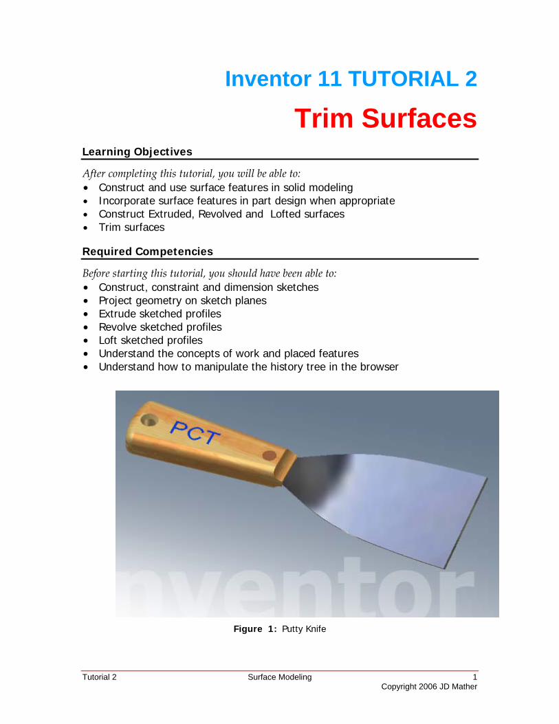
1. Open a new Standard(in).ipt . Click Return to exit sketch mode and derive Putty Knife Master Sketch.ipt with the sketches shown.
Figure 2
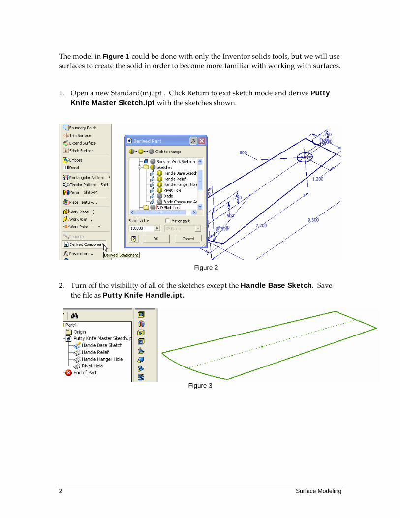
2. Turn off the visibility of all of the sketches except the Handle Base Sketch. Save
the file as Putty Knife Handle.ipt.
Figure 3
Tutorial 2 Surface Modeling 3 Copyright 2006 JD Mather
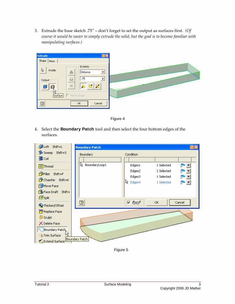
3. Extrude the base sketch .75” – don’t forget to set the output as surfaces first. (Of course it would be easier to simply extrude the solid, but the goal is to become familiar with manipulating surfaces.)
Figure 4 4. Select the Boundary Patch tool and then select the four bottom edges of the
surfaces.
Figure 5
4 Surface Modeling
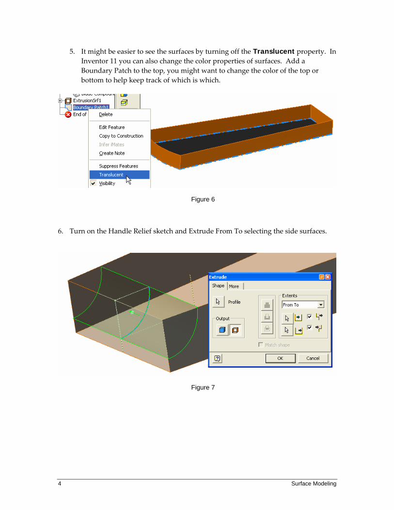
5. It might be easier to see the surfaces by turning off the Translucent property. In Inventor 11 you can also change the color properties of surfaces. Add a Boundary Patch to the top, you might want to change the color of the top or bottom to help keep track of which is which.
Figure 6
6. Turn on the Handle Relief sketch and Extrude From To selecting the side surfaces.
Figure 7
Tutorial 2 Surface Modeling 5 Copyright 2006 JD Mather
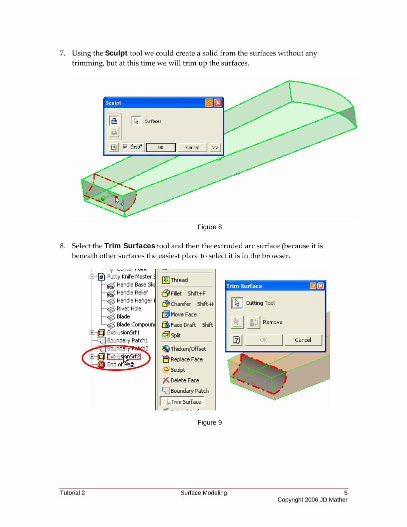
7. Using the Sculpt tool we could create a solid from the surfaces without any trimming, but at this time we will trim up the surfaces.
Figure 8
8. Select the Trim Surfaces tool and then the extruded arc surface (because it is
beneath other surfaces the easiest place to select it is in the browser.
Figure 9
6 Surface Modeling
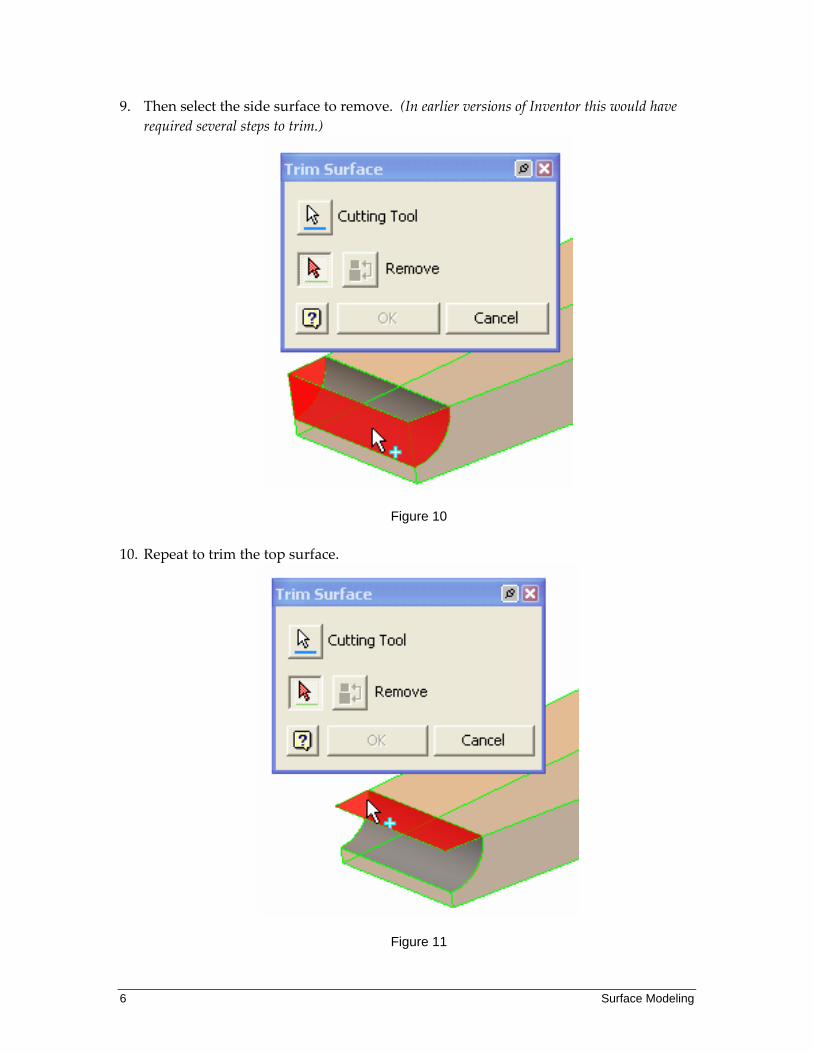
9. Then select the side surface to remove. (In earlier versions of Inventor this would have required several steps to trim.)
Figure 10
10. Repeat to trim the top surface.
Figure 11
Tutorial 2 Surface Modeling 7 Copyright 2006 JD Mather
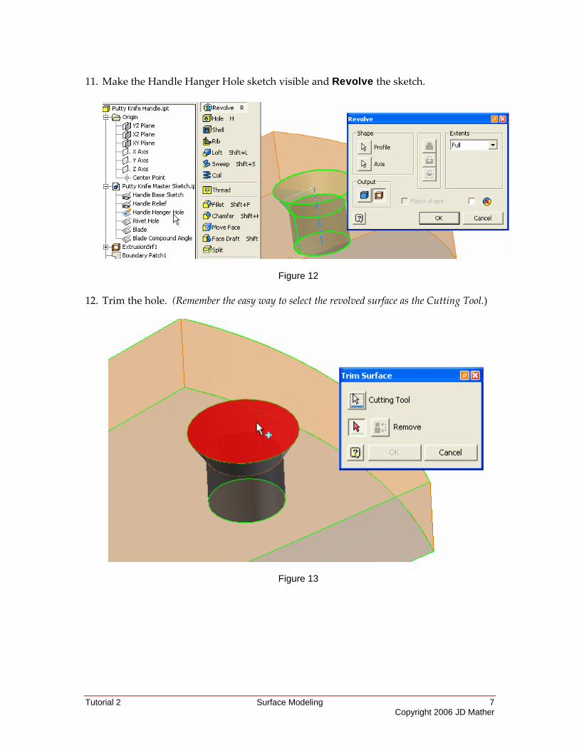
11. Make the Handle Hanger Hole sketch visible and Revolve the sketch.
Figure 12
12. Trim the hole. (Remember the easy way to select the revolved surface as the Cutting Tool.)
Figure 13
8 Surface Modeling
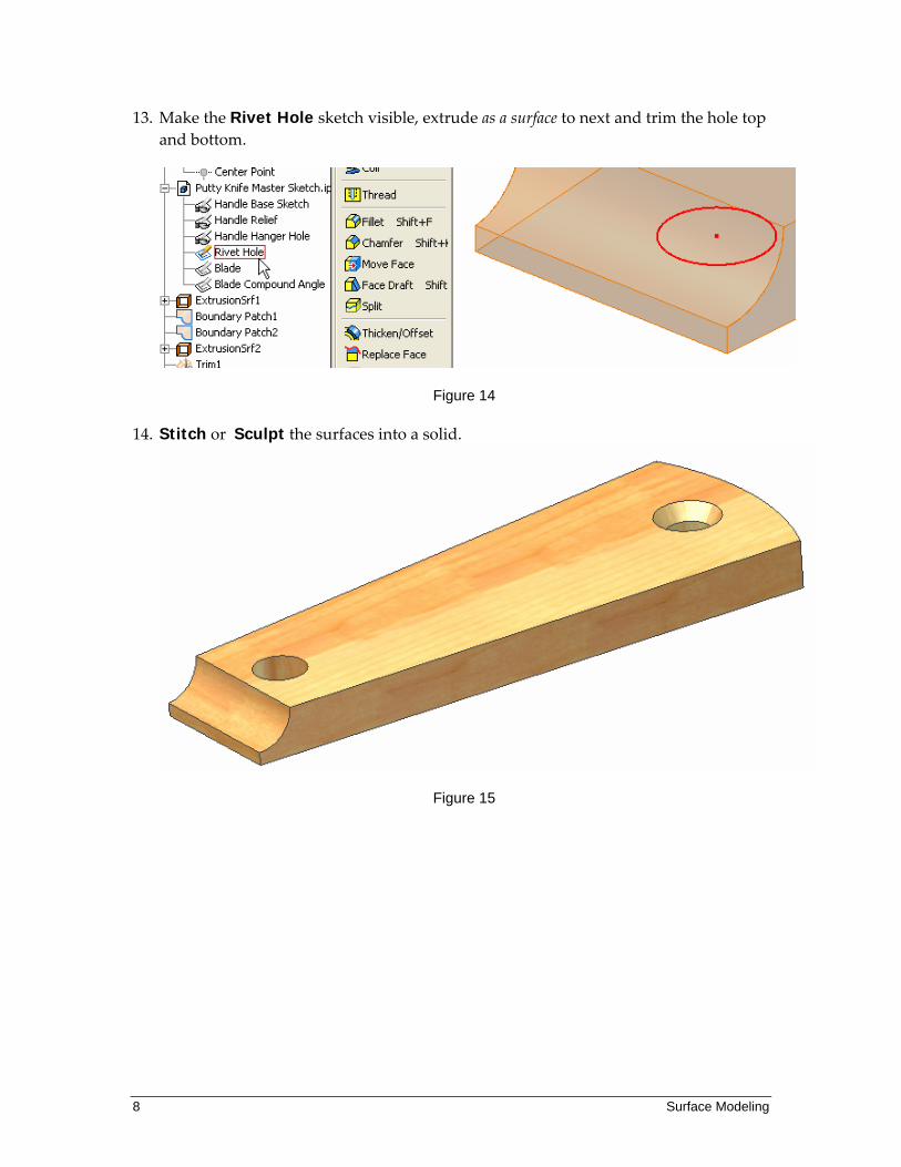
13. Make the Rivet Hole sketch visible, extrude as a surface to next and trim the hole top and bottom.
Figure 14
14. Stitch or Sculpt the surfaces into a solid.
Figure 15
Tutorial 2 Surface Modeling 9 Copyright 2006 JD Mather
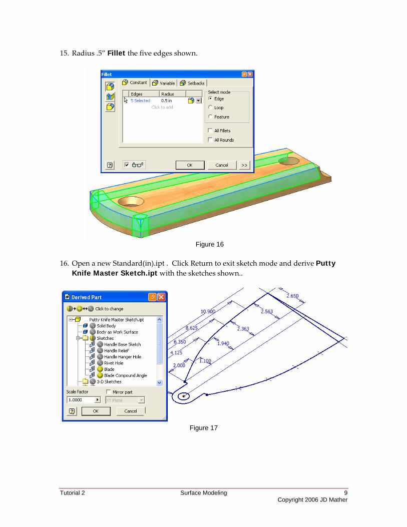
15. Radius .5” Fillet the five edges shown.
Figure 16
16. Open a new Standard(in).ipt . Click Return to exit sketch mode and derive Putty
Knife Master Sketch.ipt with the sketches shown..
Figure 17
10 Surface Modeling
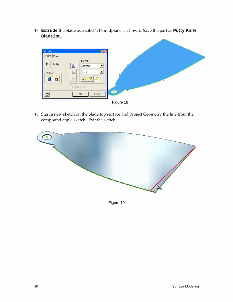
17. Extrude the blade as a solid 1/16 midplane as shown. Save the part as Putty Knife Blade.ipt.
Figure 18
18. Start a new sketch on the blade top surface and Project Geometry the line from the compound angle sketch. Exit the sketch.
Figure 19
Tutorial 2 Surface Modeling 11 Copyright 2006 JD Mather
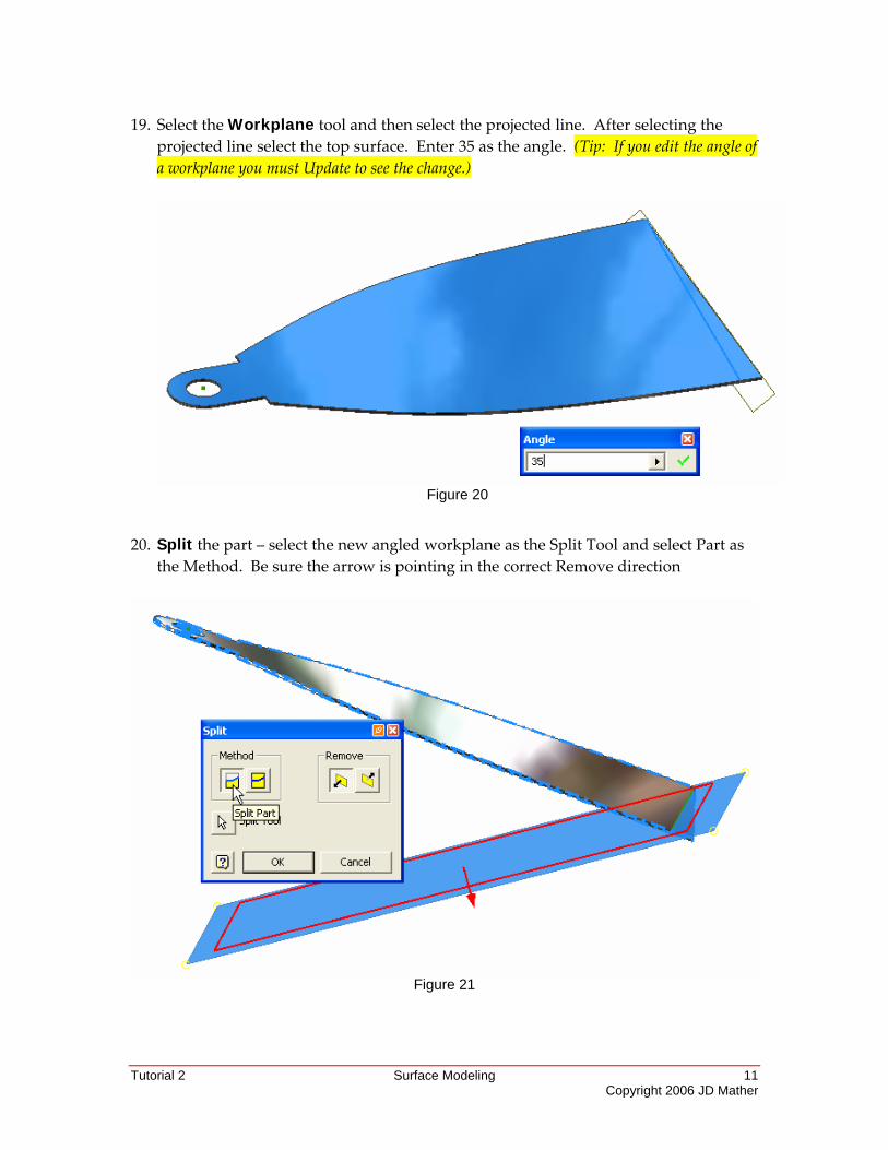
19. Select the Workplane tool and then select the projected line. After selecting the projected line select the top surface. Enter 35 as the angle. (Tip: If you edit the angle of a workplane you must Update to see the change.)
Figure 20
20. Split the part – select the new angled workplane as the Split Tool and select Part as the Method. Be sure the arrow is pointing in the correct Remove direction
Figure 21
12 Surface Modeling
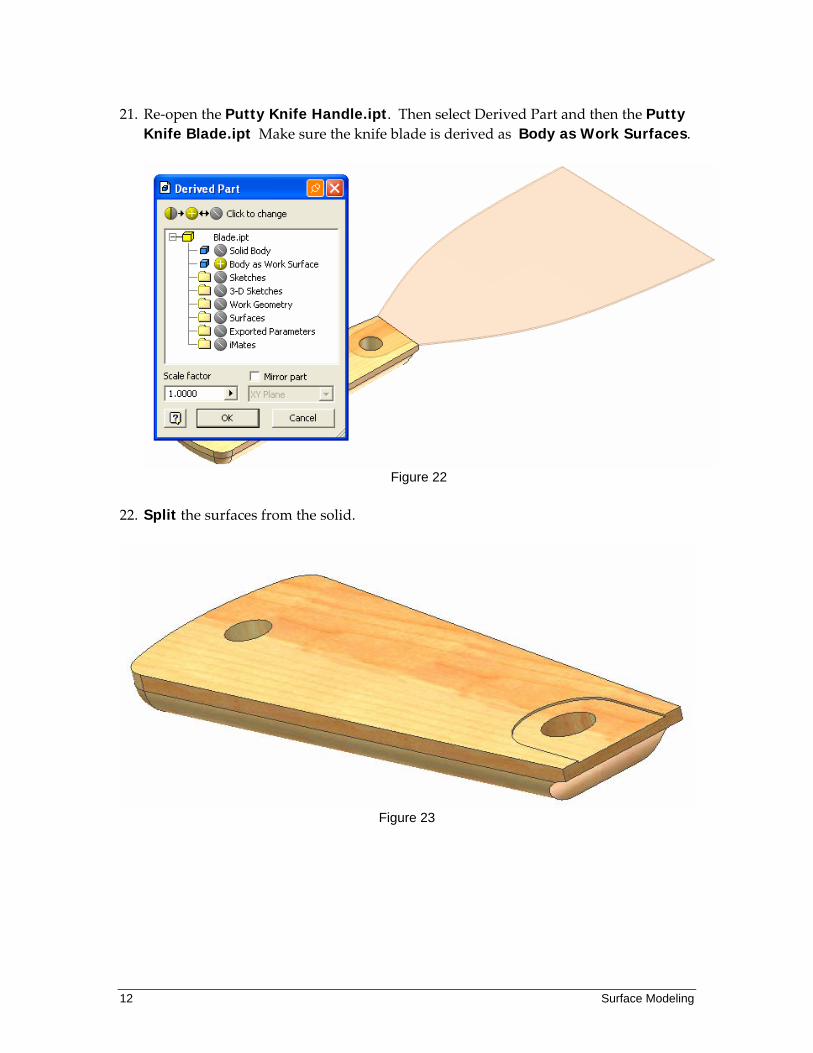
21. Re‐open the Putty Knife Handle.ipt. Then select Derived Part and then the Putty Knife Blade.ipt Make sure the knife blade is derived as Body as Work Surfaces.
Figure 22
22. Split the surfaces from the solid.
Figure 23
Tutorial 2 Surface Modeling 13 Copyright 2006 JD Mather
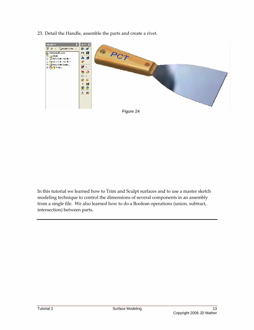
23. Detail the Handle, assemble the parts and create a rivet.
Figure 24
In this tutorial we learned how to Trim and Sculpt surfaces and to use a master sketch modeling technique to control the dimensions of several components in an assembly from a single file. We also learned how to do a Boolean operations (union, subtract, intersection) between parts.