Embed Size (px)
Citation preview

Inventec ToR/Spine
Inventec DCS7032Q28 Spine Switch Specification
Specification

Revision History
Revision Date Author Description
.01 3/30/2015 Alex Johnstone Initial Release
.02 5/28/2015 Alex Johnstone Incorporated Engineering feedback. First version submitted to the OCP.
Author: Alex Johnstone

ContentsRevision History .............................................................................................................................. 2
Contents ........................................................................................................................................... 3
Licenses ........................................................................................................................................... 5
1.1 License .......................................................................................................................... 6
Scope ................................................................................................................................................ 7
Overview .......................................................................................................................................... 7
Physical Overview ........................................................................................................................... 7
1.2 Dimensions.................................................................................................................... 7
1.3 Top View....................................................................................................................... 9
1.4 Front View .................................................................................................................... 9
1.4.1 QSFP28 Port LED Behavior ............................................................................................... 10
1.4.2 Front Panel LED Definitions .............................................................................................. 11
1.4.3 Optics and Cable Support ................................................................................................... 11
1.5 Rear View ................................................................................................................... 12
1.5.1 Field Replaceable Units ...................................................................................................... 12
1.5.1.1 Power Supply Modules ................................................................................................... 12
1.5.1.1.1 Power Supply Modules: Mechanical Drawing ......................................................... 13
1.5.1.1.2 PSU Pin-Out .............................................................................................................. 13
1.5.1.1.3 Power Supply Modules: Filter cable (Mechanical Drawing, Dimensions, and Specifications) ............................................................................................................................. 15
1.5.1.1.4 Fan Modules .............................................................................................................. 18
1.5.1.1.1 Fan Connector Pinout ................................................................................................ 19
1.6 Inventec DCS7032Q28 System Description ............................................................... 19
1.6.1 PCB Board Assemblies ....................................................................................................... 20
1.6.1.1 Switch PCB ..................................................................................................................... 20
1.6.1.2 Switch PCB Top View .................................................................................................... 21
1.6.1.3 Switch PCB Bottom View .............................................................................................. 22
1.6.1.3.1 Switch PCB Major Components ............................................................................... 22
1.6.1.3.2 Switch PCB Block Diagram...................................................................................... 23
1.6.1.3.3 Switch PCB USB cable ............................................................................................... 24
1.6.1.4 Freescale P2041 CPU Module Description..................................................................... 24
1.6.1.4.1 Freescale P2041 CPU Module Top View ................................................................. 25

1.6.1.4.2 Freescale P2041 CPU Module Bottom View ............................................................ 25
1.6.1.4.3 Freescale P2041CPU Module Major Components ................................................... 25
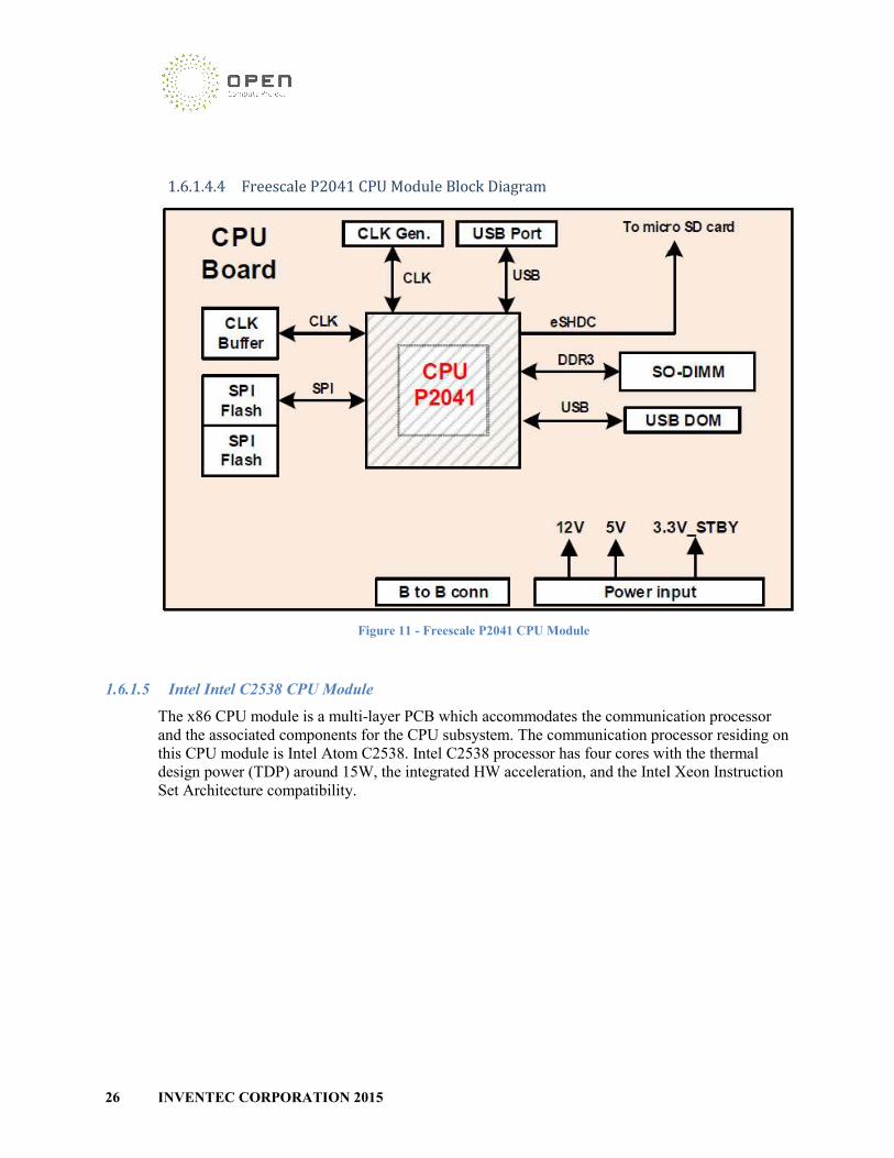
1.6.1.4.4 Freescale P2041 CPU Module Block Diagram ......................................................... 26
1.6.1.5 Intel Intel C2538 CPU Module ....................................................................................... 26
1.6.1.5.1 Intel C2538 CPU Module Top View ........................................................................ 27
1.6.1.5.2 Intel C2538 CPU Module Bottom View ................................................................... 27
1.6.1.5.3 Intel C2538 CPU Module Major Components .......................................................... 27
1.6.1.5.4 Intel C2538 CPU Module Block Diagram ................................................................ 28
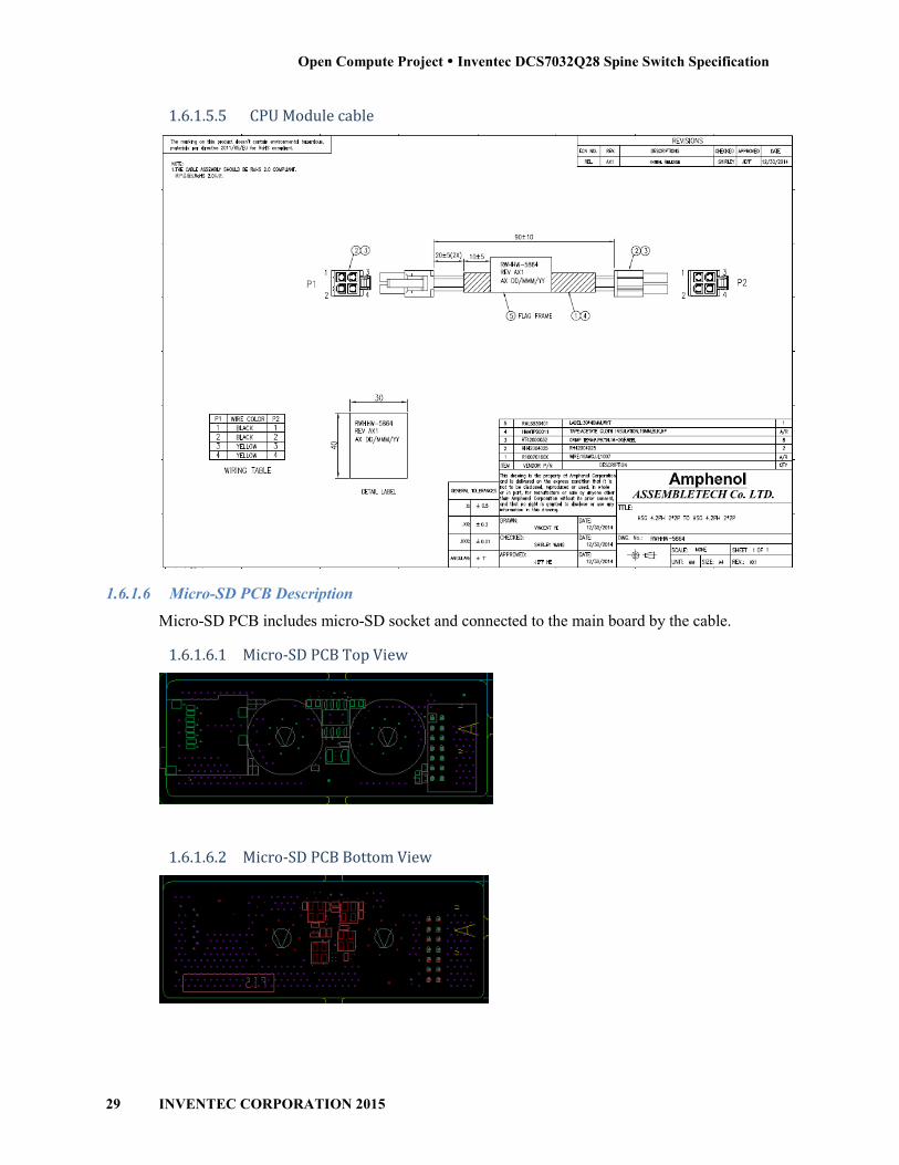
1.6.1.5.5 CPU Module cable .................................................................................................... 29
1.6.1.6 Micro-SD PCB Description ............................................................................................ 29
1.6.1.6.1 Micro-SD PCB Top View ......................................................................................... 29
1.6.1.6.2 Micro-SD PCB Bottom View ................................................................................... 29
1.6.1.6.3 Micro-SD Signal cable .............................................................................................. 30
1.6.1.7 Fan PCB Description ...................................................................................................... 30
1.6.1.7.1 Fan PCB Top View ................................................................................................... 30
1.6.1.7.2 Fan PCB Bottom View ............................................................................................. 30
1.6.1.7.3 Fan Signal Cable ....................................................................................................... 31
1.6.1.7.4 Fan Power Cable ....................................................................................................... 32
1.7 Software Support ......................................................................................................... 33
1.7.1 BIOS ................................................................................................................................... 33
1.7.2 ONIE ................................................................................................................................... 33
1.7.3 Open Network Linux (ONL) ............................................................................................... 33
1.8 Environmental Requirements ...................................................................................... 33
1.9 Regulatory Compliance ............................................................................................... 33
1.10 ROHS .......................................................................................................................... 34

Licenses All semiconductor devices that may be referred to in this specification, or required to manufacture products described in this specification, will be considered references only, and no intellectual property rights embodied in or covering such semiconductor devices shall be licensed as a result of this specification or such references. Notwithstanding anything to the contrary in the CLA, the licensed set forth therein do not apply to intellectual property rights included in or related to the semi-conductor devices identified in the Specification. These references include without limitation the references to devices listed below. For clarity, no patent claim that reads on such semiconductor devices will be considered a “Granted Claim” under the applicable Contributor License Agreement for this Specification.
Description Manufacturer Part Number
X86 CPU Intel C2538-2.4GHz FH8065501516762S R1S9
DDR3 8GB SO-DIMM w/ECC Hynix HMT41GA7BFR8A-PB
8GB SATA DOM ADATA ISMS312-008GWH
SPI NOR Flash 8MB MXIC MX25L6406EM2I-12G
pSoc Cypress CY8C3246LTI-149
CPLD Lattice LCMXO2-2000HC-4FTG256C
P2041 CPU Freescale P2041NSN7PNC 1.5GHz 1.0V
FCPBGA780 FREESCALE
4GB USB DOM ADATA IUM01-004GFHS
AC Power Supply LITEON CPR-4011-4M11 Front to back airflow
CPR-4011-4M21 Back to front airflow
Switching chip TD2 Broadcom BCM56854
10/100/1000 NIC Intel WGI210AT S LJXQ
Fan Delta GFB0412EHS-AA04 (Front to Back airflow)
GFB0412EHS-AA04 (Back to Front airflow)
Cage/Conn. QSFP28 2x2 (x8) Molex U172564-2001
Connector RJ45 2x1 (x1) Amphenol RJMG221MD44B9ER
Table 1 – Licensed Components
1.1 License
As of May 25, 2015, the following persons or entities have made this Specification available under the Open Compute Project Hardware License (Copyleft) Version 1.0 (OCPHL-P), which is available at http://www.opencompute.org/community/getinvolved/spec-submission-process/
INVENTEC CORPORATION
Your use of this Specification may be subject to other third party rights. THIS SPECIFICATION IS PROVIDED "AS IS." The contributors expressly disclaim any warranties (express, implied, or otherwise), including implied warranties of merchantability, non-infringement, fitness for a particular purpose, or title, related to the Specification. The entire risk as to implementing or otherwise using the Specification is assumed by the Specification implementer and user. IN NO EVENT WILL ANY PARTY BE LIABLE TO ANY OTHER PARTY FOR LOST PROFITS OR ANY FORM OF INDIRECT, SPECIAL, INCIDENTAL, OR CONSEQUENTIAL DAMAGES OF ANY CHARACTER FROM ANY CAUSES OF ACTION OF ANY KIND WITH RESPECT TO THIS SPECIFICATION OR ITS GOVERNING AGREEMENT, WHETHER BASED ON BREACH OF CONTRACT, TORT (INCLUDING NEGLIGENCE), OR OTHERWISE, AND WHETHER OR NOT THE OTHER PARTY HAS BEEN ADVISED OF THE POSSIBILITY OF SUCH DAMAGE. This specification is being submitted under the Open Compute Project Hardware License (Permissive)

Open Compute Project Inventec DCS7032Q28 Spine Switch Specification
7 INVENTEC CORPORATION 2015
Scope This document defines the technical specifications for the Inventec DCS7032Q28 submitted to the Open Compute Foundation.
Overview The Inventec DCS7032Q28 is a 1U-chassis system, which is targeted at the of TOR (Top-of-Rack)/Spine application and is a PHY-less switch solution. The port configurations on the Redwood switch are thirty-two 100G QSFP28 ports. They can achieve a maximum bandwidth of 3200 Gbps. The user interfaces contain one GbE management ports, one console port, one micro SD card and one USB 2.0 port.
The Inventec DCS7032Q28 contains one CPU board, one Switch board, one FAN board and one daughter board. There are also five 2-rotor fans and two 550W PSUs installed in the box on the rear side of chassis. The PSUs and fans are all hot-swappable.
BCM56960, Tomahawk, is the switch chip used to provide the high bandwidth switching. Since the Inventec DCS7032Q28 uses a PHY-less solution, the Tomahawk is connected directly to thirty-two 100G QSFP28 ports.
The Freescale P2041 is the embedded processor. One memory slot channel of DDR3 SO-DIMM is supported, and maximum capacity is 8GBytes (1x8GBytes). The system boots from BIOS located in SPI memory, and then run OS from either a USB DOM or from a micro SD card.
For redundancy in the design, the Redwood system supports 1+1 PSU redundancy and 4+1 fan redundancy. In addition, it has a backup SPI FLASH which will be activated in the case that the primary SPI image is corrupted.
Physical Overview
1.2 Dimensions
Inches Millimeters
Length 17.0 431.93
Width 17.32 440
Height 1.7 43.18
Table 2 - Inventec DCS7032Q28 Physical Dimensions

8 INVENTEC CORPORATION 2015
Figure
INVENTEC CORPORATION 2015
Figure 1 - Inventec DCS7032Q28 Physical Dimensions

Open Compute Project Inventec DCS7032Q28 Spine Switch Specification
9 INVENTEC CORPORATION 2015
1.3 Top View
The top view of the Inventec DCS7032Q28 shows the Printed Circuit Boards, and other chassis components of the system. Locations of the CPLDs, ASIC, and CPU Module are also highlighted.
Figure 2 – Inventec DCS7032QS Top View with Key Components Identified
1.4 Front View
Figure 3 - Inventec DCS7032Q28 Front View

10 INVENTEC CORPORATION 2015
The front panel view of the Inventec
Thirty-two (32) QSFP28 Ports
Two (2) IEC AC Power Jacks (1
Port Status LEDs
QSFP28 Mode LEDs
RJ-45 (RS-232) Console Port
RJ-45 10/100/1000 Ethernet Management Port
System Status LED
Reset Switch
1.4.1 QSFP28 Port LED Behavior
Figure
INVENTEC CORPORATION 2015
The front panel view of the Inventec DCS7032Q28 includes the following components:
two (32) QSFP28 Ports
Two (2) IEC AC Power Jacks (1 Located on Each Side of Chassis)
QSFP28 Mode LEDs
232) Console Port
45 10/100/1000 Ethernet Management Port
System Status LED
QSFP28 Port LED Behavior
Figure 4 - Inventec DCS7032Q28 QSFP28 Port LED Behavior
includes the following components:

Open Compute Project Inventec DCS7032Q28 Spine Switch Specification
11 INVENTEC CORPORATION 2015
1.4.2 Front Panel LED Definitions
Function Color Status Description
QSFP28 mode
LED (bi-color)
Green
(520nm~535nm)
Solid (Both Left and Right) 100G Mode
Solid (Left Only) 40G Mode
Solid (Left Only) 25G Mode
Off (Both Left and Right) 10G Mode
Red
(617.5nm~629.5nm) Solid (Both Left and Right) Port Fail
QSFP28
Link/Activity LED
Green
(520nm~535nm)
Solid Link Up
Blinking Activity – XMT/RCV
Off Link Down
Management port
GbE Link LEDs
Green
(568nm)
Solid Link Up
Off Link Down
Management port
GbE Activity LEDs
Green
(568nm)
Blinking Activity – XMT/RCV
Off No Activity
Table 3 - Inventec DCS7032Q28 Front Panel LED Definitions
1.4.3 Optics and Cable Support
40Gb QSFP+ Optical Modules Standard 40Gb QSFP+ modules including and not limited to: 40GBASE‐SR4, 40GBASE‐LR4, 40GBASE‐ER, AOC Cables
40Gb Direct Attach Copper (DAC) Standard DAC cables including and not limited to: Passive cables up to 7m,QSFP-to-QSFP DAC, QSFP-to-SFP+ DAC Breakout
QSFP28 Optics Support for all standards complaint QSFP28 Transceivers including and not limited to 100GBASE‐SR4, 100GBASE‐LR4
QSFP28 Direct Attach Copper (DAC) Standard DAC cables including but not limited to: Passive cables up to 3m, QSFP28-to-QSFP28 DAC, QSFP28-to-SFP28 DAC Breakout
Table 4 - Inventec DCS7032Q28 Optics and Cable Support

12 INVENTEC CORPORATION 2015
1.5 Rear View
The rear view of the Inventec
Two (1+1) Redundant, Hot Swappable, Power Supply Modules
o Status LED (Per Power Supply)
o Color Coding to Indicate Airflow Direction
Five (4+1) Redundant, Hot Swappable, Fan Modules
o 2 LEDs Per Fan Module to Indica
1.5.1 Field Replaceable Units
1.5.1.1 Power Supply Modules
The Inventec DCS7032Q28following table.
Make-Liteon 550 Watt PSU: AC Input Range: 115
PS-2551-1L-LF Front
Length
Width
Height
INVENTEC CORPORATION 2015
Figure 5 - Inventec DCS7032Q28 Rear View
The rear view of the Inventec DCS7032Q28 includes the following components:
Two (1+1) Redundant, Hot Swappable, Power Supply Modules
Status LED (Per Power Supply)
Color Coding to Indicate Airflow Direction
+1) Redundant, Hot Swappable, Fan Modules
Per Fan Module to Indicate Status (Red, Green)
DCS7032Q28 supports two (1+1) redundant power supply modules as listed in the
Watt PSU: AC Input Range: 115-230 VAC / xx-yyHz
Front-to-Rear Airflow
Inches Millimeters
9.45
2.02
1.52
Table 5 - PSU Options and Dimensions
includes the following components:
supports two (1+1) redundant power supply modules as listed in the
240.00
51.30
38.5

Open Compute Project Inventec DCS7032Q28 Spine Switch Specification
13 INVENTEC CORPORATION 2015
1.5.1.1.1 Power Supply Modules: Mechanical Drawing
Figure 6 - Inventec DCS7032Q28 PSU Module Drawing
1.5.1.1.2 PSU Pin-Out
Table 6 - Inventec DCS7032Q28 Golden Fingers Pinout Defintions

14 INVENTEC CORPORATION 2015
Figure 7 - Inventec DCS7032Q28 Golden Fingers Mechanical Drawing
INVENTEC CORPORATION 2015
Inventec DCS7032Q28 Golden Fingers Mechanical Drawing
Inventec DCS7032Q28 Golden Fingers Mechanical Drawing
Open Compute Project Inventec DCS7032Q28 Spine Switch Specification
15 INVENTEC CORPORATION 2015
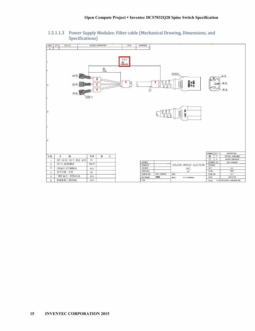
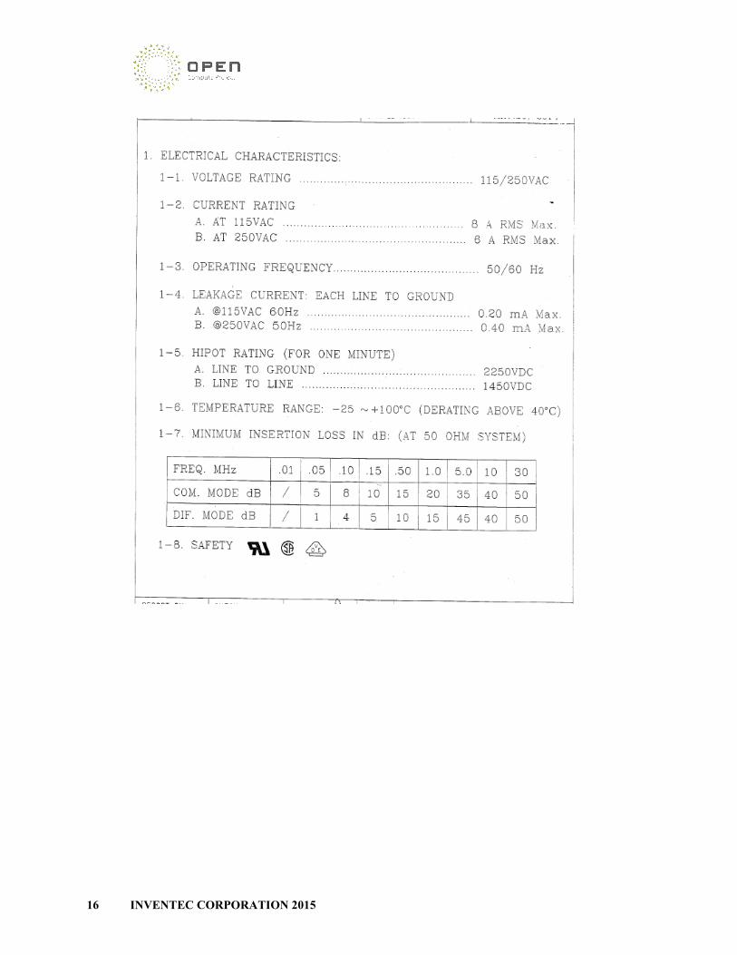
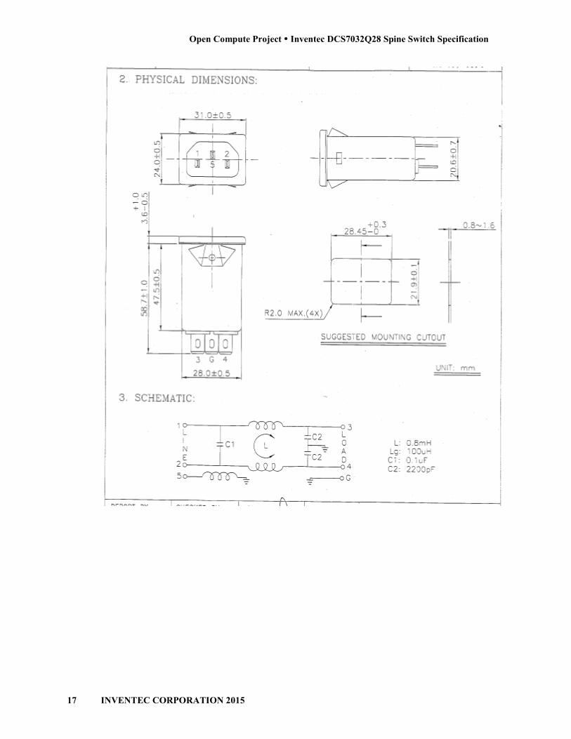
1.5.1.1.3 Power Supply Modules: Filter cable (Mechanical Drawing, Dimensions, and Specifications)
16 INVENTEC CORPORATION 2015INVENTEC CORPORATION 2015
Open Compute Project Inventec DCS7032Q28 Spine Switch Specification
17 INVENTEC CORPORATION 2015

18 INVENTEC CORPORATION 2015
1.5.1.1.4 Fan Modules
The Inventec DCS7032Q2840 mmx40 mmx56 mm fans.
Description
Fan (Front-to-Rear Airflow)
Fan (Rear-to-Front Airflow)
INVENTEC CORPORATION 2015
DCS7032Q28 supports five individual fan modules. Each fan module supports two mm fans.
Manufacturer Part Number
Airflow) Delta GFB0412EHS-AA04
Front Airflow) Delta GFB0412EHS-AA04
Table 7 - Fan Modules
supports five individual fan modules. Each fan module supports two
AA04
AA04
Open Compute Project Inventec DCS7032Q28 Spine Switch Specification
19 INVENTEC CORPORATION 2015
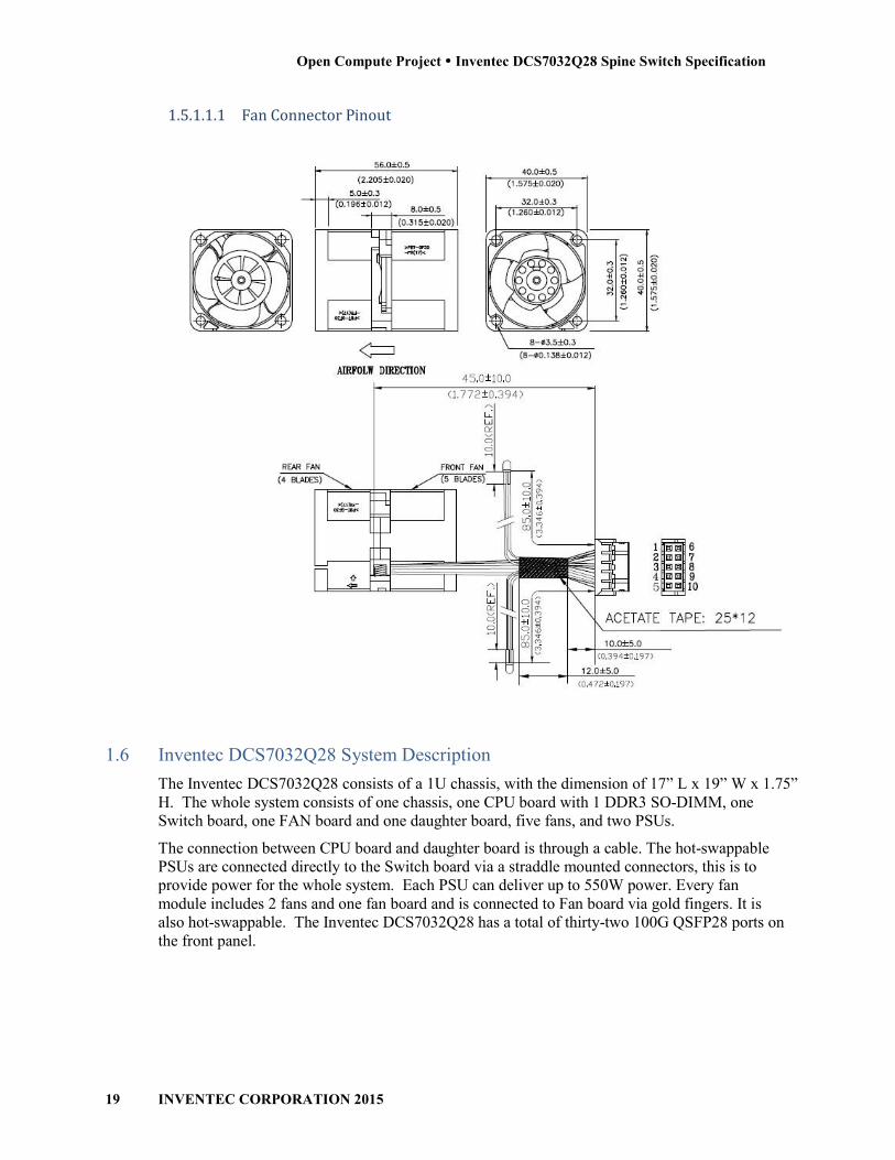
1.5.1.1.1 Fan Connector Pinout
1.6 Inventec DCS7032Q28 System Description
The Inventec DCS7032Q28 consists of a 1U chassis, with the dimension of 17” L x 19” W x 1.75” H. The whole system consists of one chassis, one CPU board with 1 DDR3 SO-DIMM, one Switch board, one FAN board and one daughter board, five fans, and two PSUs.
The connection between CPU board and daughter board is through a cable. The hot-swappable PSUs are connected directly to the Switch board via a straddle mounted connectors, this is to provide power for the whole system. Each PSU can deliver up to 550W power. Every fan module includes 2 fans and one fan board and is connected to Fan board via gold fingers. It is also hot-swappable. The Inventec DCS7032Q28 has a total of thirty-two 100G QSFP28 ports on the front panel.

20 INVENTEC CORPORATION 2015
1.6.1 PCB Board Assemblies
The Inventec DCS7032Q28
Description
Switch PCB
CPU Module PCB
Micro-SD PCB
Fan tray module PCB
Fan PCB
1.6.1.1 Switch PCB
The Switch PCB is a multi-front panel networking and management ports, LEDs, and the connections to other PCB boards in the system.
INVENTEC CORPORATION 2015
DCS7032Q28 is comprised of the following four (4) PCB assembl
Dimensions Layers
12.29in x 16.98in x 0.12in (309.214mm x 431.292mm x 3.048mm)
20
3.38in x 8.72in x 0.085in (85.85mm x 221.5mm x 2.16mm)
10
0.91in x 2.50in x 0.093in (23.12mm x 63.5mm x 2.36mm)
6 Layers
1.52in x 1.18in x 0.062in (38.5mm x 30mm x 1.58mm)
4 Layers
1.44in x 9.61in x 0.062in (36.58mm x 244.10mm x 1.57mm)
4 Layers
-layer board supporting the Broadcom Tomahawk switching silicon, front panel networking and management ports, LEDs, and the connections to other PCB boards in
is comprised of the following four (4) PCB assemblies:
Layers
Layers
Layers
6 Layers
Layers
Layers
switching silicon, front panel networking and management ports, LEDs, and the connections to other PCB boards in

Open Compute Project Inventec DCS7032Q28 Spine Switch Specification
21 INVENTEC CORPORATION 2015
1.6.1.2 Switch PCB Top View
Figure 8 - Inventec DCS7032Q28 Switch PCB Top View With Major Components Highlighted
22 INVENTEC CORPORATION 2015
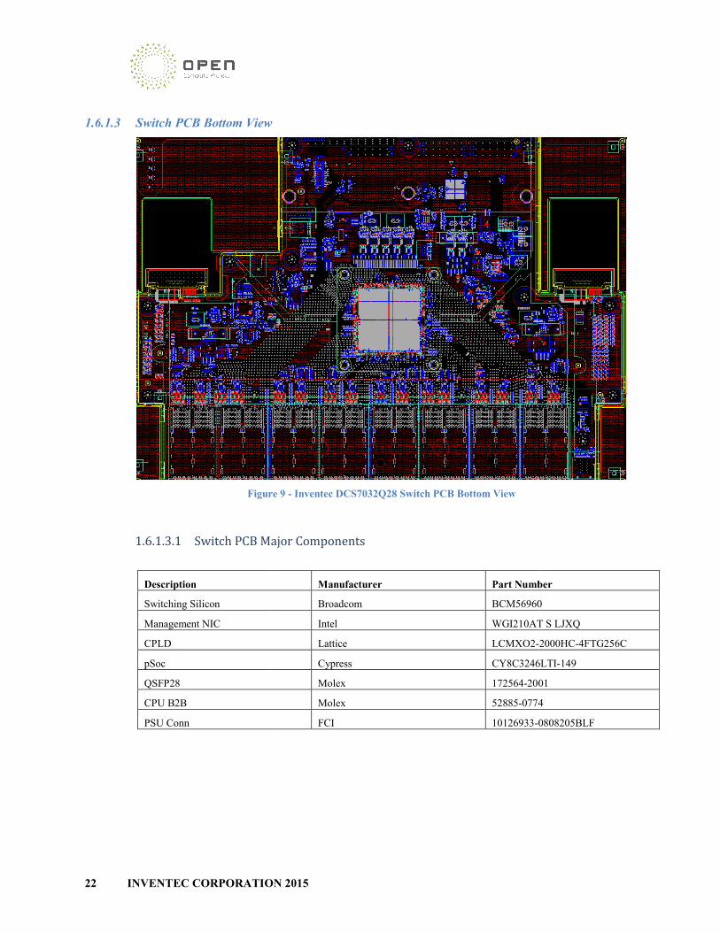
1.6.1.3 Switch PCB Bottom View
Figure
1.6.1.3.1 Switch PCB Major Components
Description
Switching Silicon
Management NIC
CPLD
pSoc
QSFP28
CPU B2B
PSU Conn
INVENTEC CORPORATION 2015
Switch PCB Bottom View
Figure 9 - Inventec DCS7032Q28 Switch PCB Bottom View
Switch PCB Major Components
Manufacturer Part Number
Broadcom BCM56960
Intel WGI210AT S LJXQ
Lattice LCMXO2-
Cypress CY8C3246LTI
Molex 172564-2001
Molex 52885-0774
FCI 10126933-0808205BLF
Part Number
BCM56960
WGI210AT S LJXQ
-2000HC-4FTG256C
CY8C3246LTI-149
2001
0774
0808205BLF

Open Compute Project Inventec DCS7032Q28 Spine Switch Specification
23 INVENTEC CORPORATION 2015
1.6.1.3.2 Switch PCB Block Diagram
Figure 10 - Inventec DCS7032Q28 Main PCB Block Diagram

24 INVENTEC CORPORATION 2015
1.6.1.3.3 Switch PCB USB cable
1.6.1.4 Freescale P2041 CPU Module Description
The P2041 CPU module is a multiand the associated components for the CPU subsystem. The processor residing on this CPU module is Freescale P2041 QorIQ integrated communication processor which providPower Architecture® processor cores with high performance data path acceleration logic and peripheral bus interfaces required for Networking and Telecommunication.
INVENTEC CORPORATION 2015
USB cable
CPU Module Description
The P2041 CPU module is a multi-layer PCB which accommodates the communication processor and the associated components for the CPU subsystem. The processor residing on this CPU module is Freescale P2041 QorIQ integrated communication processor which provid
Architecture® processor cores with high performance data path acceleration logic and peripheral bus interfaces required for Networking and Telecommunication.
layer PCB which accommodates the communication processor and the associated components for the CPU subsystem. The processor residing on this CPU module is Freescale P2041 QorIQ integrated communication processor which provides four
Architecture® processor cores with high performance data path acceleration logic and

Open Compute Project Inventec DCS7032Q28 Spine Switch Specification
25 INVENTEC CORPORATION 2015
1.6.1.4.1 Freescale P2041 CPU Module Top View
1.6.1.4.2 Freescale P2041 CPU Module Bottom View
1.6.1.4.3 Freescale P2041CPU Module Major Components
Description Manufacturer Part Number P2041 CPU Freescale P2041NSN7PNC 1.5GHz 1.0V
FCPBGA780 FREESCALE DDR3 8GB SO-DIMM w/ECC
Hynix HMT41GA7BFR8A-PB
4GB USB DOM ADATA IUM01-004GFHS
26 INVENTEC CORPORATION 2015
1.6.1.4.4 Freescale P2041
1.6.1.5 Intel Intel C2538 CPU Module
The x86 CPU module is a multiand the associated components for the CPU substhis CPU module is Intel Atom C2538. Intel C2538 processor has four cores with the thermal design power (TDP) around 15W, the integrated HW acceleration, and the Intel Xeon Instruction Set Architecture compatibility.
INVENTEC CORPORATION 2015
Freescale P2041 CPU Module Block Diagram
Figure 11 - Freescale P2041 CPU Module
Intel Intel C2538 CPU Module
The x86 CPU module is a multi-layer PCB which accommodates the communication processor and the associated components for the CPU subsystem. The communication processor residing on this CPU module is Intel Atom C2538. Intel C2538 processor has four cores with the thermal design power (TDP) around 15W, the integrated HW acceleration, and the Intel Xeon Instruction
bility.
layer PCB which accommodates the communication processor ystem. The communication processor residing on
this CPU module is Intel Atom C2538. Intel C2538 processor has four cores with the thermal design power (TDP) around 15W, the integrated HW acceleration, and the Intel Xeon Instruction

Open Compute Project Inventec DCS7032Q28 Spine Switch Specification
27 INVENTEC CORPORATION 2015
1.6.1.5.1 Intel C2538 CPU Module Top View
1.6.1.5.2 Intel C2538 CPU Module Bottom View
1.6.1.5.3 Intel C2538 CPU Module Major Components
Description Manufacturer Part Number
CPU Intel C2538
FH8065501516762S R1S9
8GB DDR3 SODIMM Hynixx HMT41GA7BFR8A-PB
SATA DOM 8GB ADATA ISMS312-008GWH

28 INVENTEC CORPORATION 2015
1.6.1.5.4 Intel C2538 CPU Module Block Diagram
INVENTEC CORPORATION 2015
Intel C2538 CPU Module Block Diagram
Figure 12 - Intel C2538 CPU Module
Open Compute Project Inventec DCS7032Q28 Spine Switch Specification
29 INVENTEC CORPORATION 2015
1.6.1.5.5 CPU Module cable
1.6.1.6 Micro-SD PCB Description
Micro-SD PCB includes micro-SD socket and connected to the main board by the cable.
1.6.1.6.1 Micro-SD PCB Top View
1.6.1.6.2 Micro-SD PCB Bottom View

30 INVENTEC CORPORATION 2015
1.6.1.6.3 Micro-SD Signal
1.6.1.7 Fan PCB Description
The Fan board is 4 layers PCB and provides power, management and connectivity for 4 system Fan module. The Fan PCB connects to main system Fan.
1.6.1.7.1 Fan PCB Top View
1.6.1.7.2 Fan PCB Bottom View
INVENTEC CORPORATION 2015
Signal cable
The Fan board is 4 layers PCB and provides power, management and connectivity for 4 system connects to main switch board with small cable for power and monitor
Fan PCB Top View
Fan PCB Bottom View
The Fan board is 4 layers PCB and provides power, management and connectivity for 4 system e for power and monitor

Open Compute Project Inventec DCS7032Q28 Spine Switch Specification
31 INVENTEC CORPORATION 2015
1.6.1.7.3 Fan Signal Cable

32 INVENTEC CORPORATION 2015
1.6.1.7.4 Fan Power Cable
INVENTEC CORPORATION 2015

Open Compute Project Inventec DCS7032Q28 Spine Switch Specification
33 INVENTEC CORPORATION 2015
1.7 Software Support
1.7.1 BIOS
A BIOS provided by AMI with our customization will be used. Diagnostics will be run at the UEFI shell.
1.7.2 ONIE
ONIE is supported.
1.7.3 Open Network Linux (ONL)
ONL is supported.
1.8 Environmental Requirements
0 to 45 Degrees C standard operating range
-40 to 70 Degrees C storage
Humidity 10% to 90% non‐condensing
Vibration – IEC 68‐2‐36, IEC 68‐2‐6
Shock – IEC 68‐2‐29
Acoustic Noise Level – Under 60dB in 40 degree C
1.9 Regulatory Compliance
The system meets the regulatory compliances and safety requirements of North America, EU, China, Japan, Taiwan, Singapore, India, and South Korea.
FCC part 15 and CISPR 22 Class A
EN 61000-3-2 Harmonics
EN 61000-3-3 Voltage Flicker
EN 55024 Immunity
EN 61000-4-2 Electrostatic Discharge, 8kV Contact, 15 kV Air,
EN 61000-4-3 Radiated Immunity 3V/m, Criteria A
EN 61000-4-4 Transient Burst, 1 kV, Criteria B
EN 61000-4-5 Surge, 2 kV L-L, 2 kV L-G, Level 3, Criteria B
EN 61000-4-6 Conducted Immunity, 0.15-80 MHz, 3V
EN 61000-4-11 Power Dips & Interruptions, >30%, 25 periods

34 INVENTEC CORPORATION 2015
1.10 ROHS
Restriction of Hazardous Substances (6/6)
Compliance with Environmental procedure 020499Hazardous Substances (ROHS Directive 2002/95/EC) and Waste and Electrical and Electronic Equipment (WEEE Directive 2002/96/EC)
INVENTEC CORPORATION 2015
Restriction of Hazardous Substances (6/6)
Compliance with Environmental procedure 020499‐00 primarily focused on Restriction of Substances (ROHS Directive 2002/95/EC) and Waste and Electrical and Electronic
Equipment (WEEE Directive 2002/96/EC)
00 primarily focused on Restriction of Substances (ROHS Directive 2002/95/EC) and Waste and Electrical and Electronic