Embed Size (px)
Citation preview
INVELOX OPTIMIZATIONInvelox Tower CFD Test - Flow From Different Directions
Instructor : Professor Yiannis Andreopoulos
Student : M.E. Mehmet Bariskan
HOW IT WORKS ?
• Capture, accelerate, concentrate. The name INVELOX comes from this dedication to INcreasing the VELOcity of wind. What the technology produces-energy is affordable, abundant, safe, and clean.
• INVELOX, by contrast, funnels wind energy to ground –base generators. Wind is captured with a funnel and directed through a tapering passageway that naturally accelerates its flow. This stream of kinetic energy then drives a generator that is installed safely and economically at ground level.
• Bringing the airflow from top of the tower to ground level allows for greater power generation with much smaller turbine blades. It also allows for networking, allowing multiple towers to direct energy to the same generator.
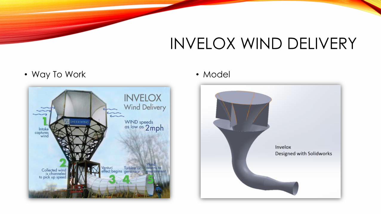
INVELOX WIND DELIVERY
• Way To Work • Model

COMPARISON OF 4 FLOW MODELS
1. From (+x) direction 2. From reverse direction called (-x)
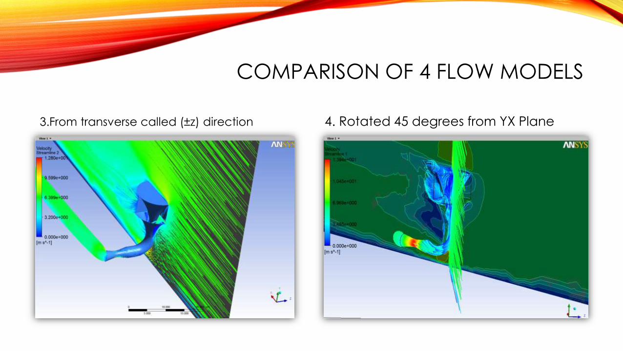
COMPARISON OF 4 FLOW MODELS
3.From transverse called (±z) direction 4. Rotated 45 degrees from YX Plane
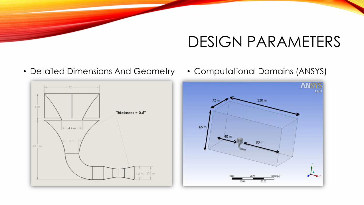
DESIGN PARAMETERS
• Detailed Dimensions And Geometry • Computational Domains (ANSYS)

MESHING (ANSYS)
Medium Mesh 1.9 M Elements
443039 Nodes
Settings
Medium/Inflation to Invelox
Fine Mesh 3.4 M Elements
801317 Nodes
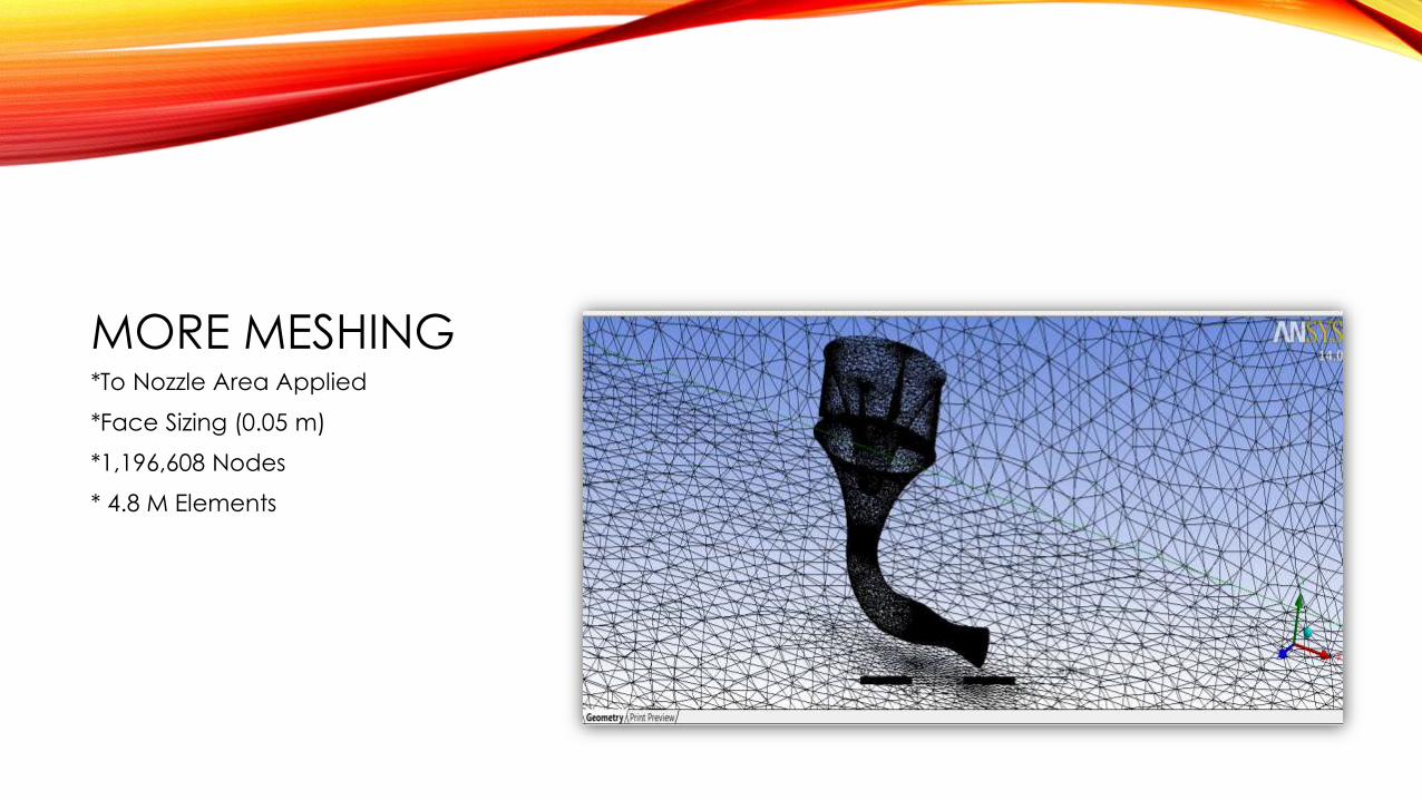
MORE MESHING*To Nozzle Area Applied
*Face Sizing (0.05 m)
*1,196,608 Nodes
* 4.8 M Elements
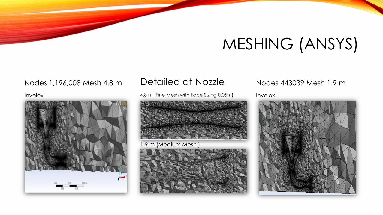
MESHING (ANSYS)
Nodes 1,196,008 Mesh 4.8 m
Invelox
Detailed at Nozzle
4.8 m (Fine Mesh with Face Sizing 0.05m)
1.9 m (Medium Mesh )
Nodes 443039 Mesh 1.9 m
Invelox

BOUNDARY CONDITIONS
• Inlet = 6.7056 m/s
• Outlet = 0 (Gauge Pressure)
• Invelox = Roughness Constant 0.5
• %5 Turbulance Intensity/ 0.01m Length
• Wall = No Slip
• Ref. Value = Inlet
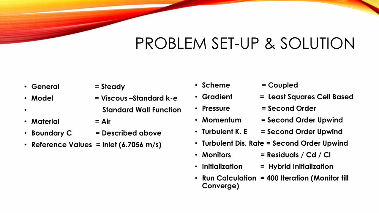
PROBLEM SET-UP & SOLUTION
• General = Steady
• Model = Viscous –Standard k-e
• Standard Wall Function
• Material = Air
• Boundary C = Described above
• Reference Values = Inlet (6.7056 m/s)
• Scheme = Coupled
• Gradient = Least Squares Cell Based
• Pressure = Second Order
• Momentum = Second Order Upwind
• Turbulent K. E = Second Order Upwind
• Turbulent Dis. Rate = Second Order Upwind
• Monitors = Residuals / Cd / Cl
• Initialization = Hybrid Initialization
• Run Calculation = 400 Iteration (Monitor till Converge)
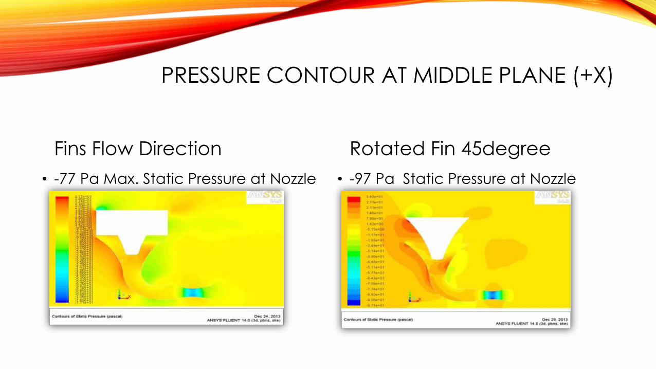
PRESSURE CONTOUR AT MIDDLE PLANE (+X)
Fins Flow Direction
• -77 Pa Max. Static Pressure at Nozzle
Rotated Fin 45degree
• -97 Pa Static Pressure at Nozzle
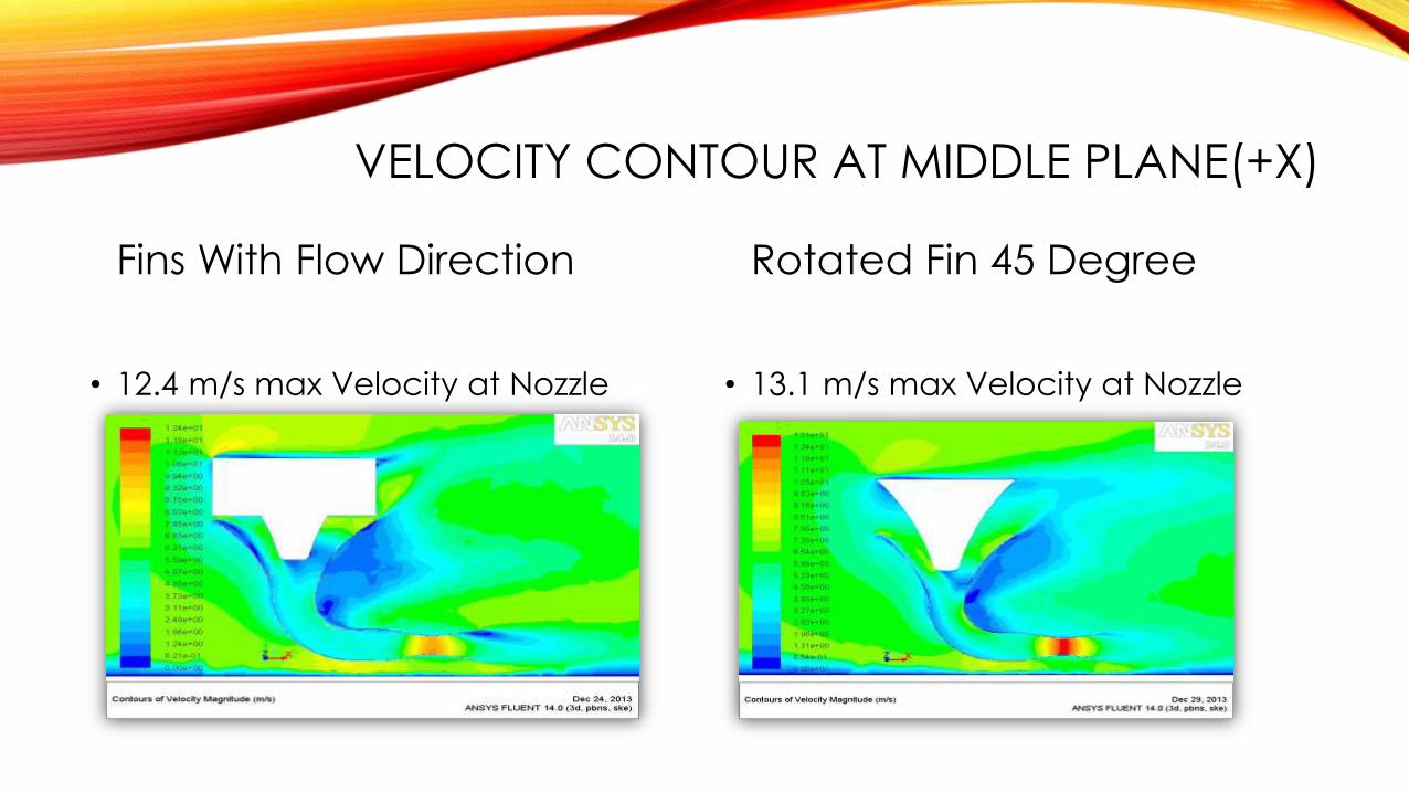
VELOCITY CONTOUR AT MIDDLE PLANE(+X)
Fins With Flow Direction
• 12.4 m/s max Velocity at Nozzle
Rotated Fin 45 Degree
• 13.1 m/s max Velocity at Nozzle
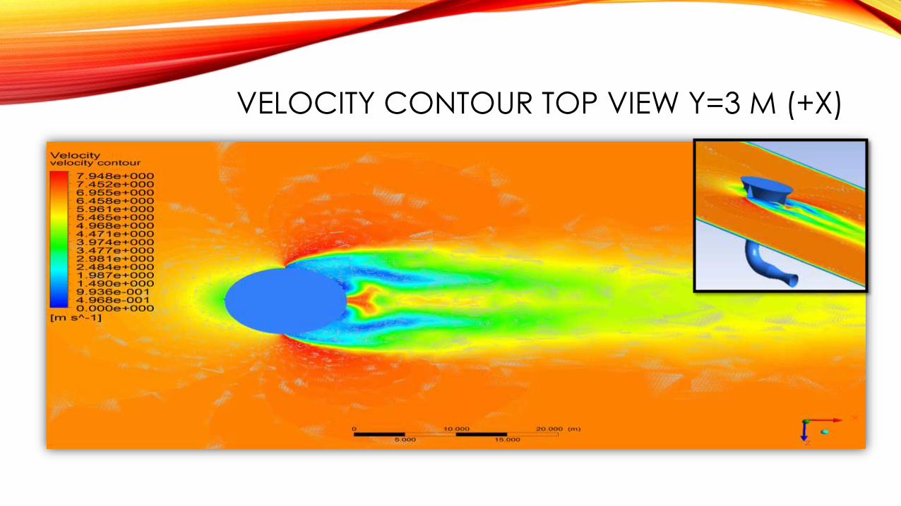
VELOCITY CONTOUR TOP VIEW Y=3 M (+X)
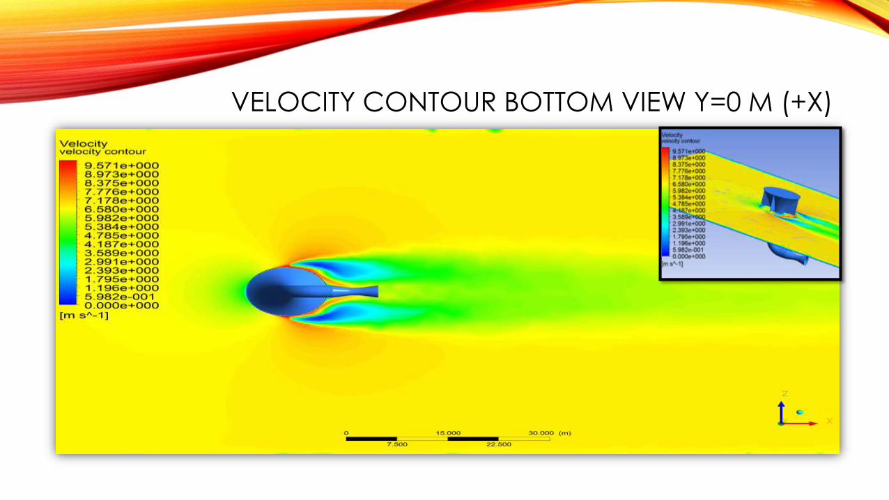
VELOCITY CONTOUR BOTTOM VIEW Y=0 M (+X)

VELOCITY CONTOUR TOP VIEW Y=(-)12 M (+X)
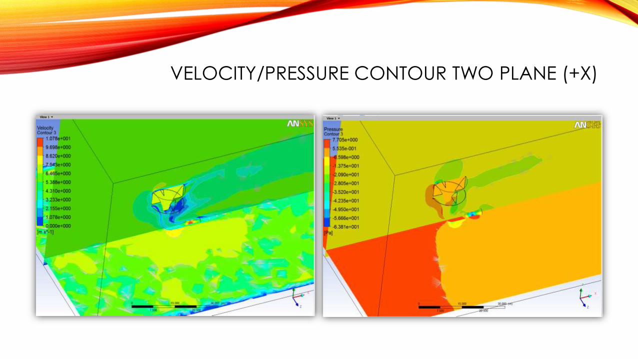
VELOCITY/PRESSURE CONTOUR TWO PLANE (+X)

VELOCITY VECTOR & TURBULENCE ENERGY XY PLANE (+X)
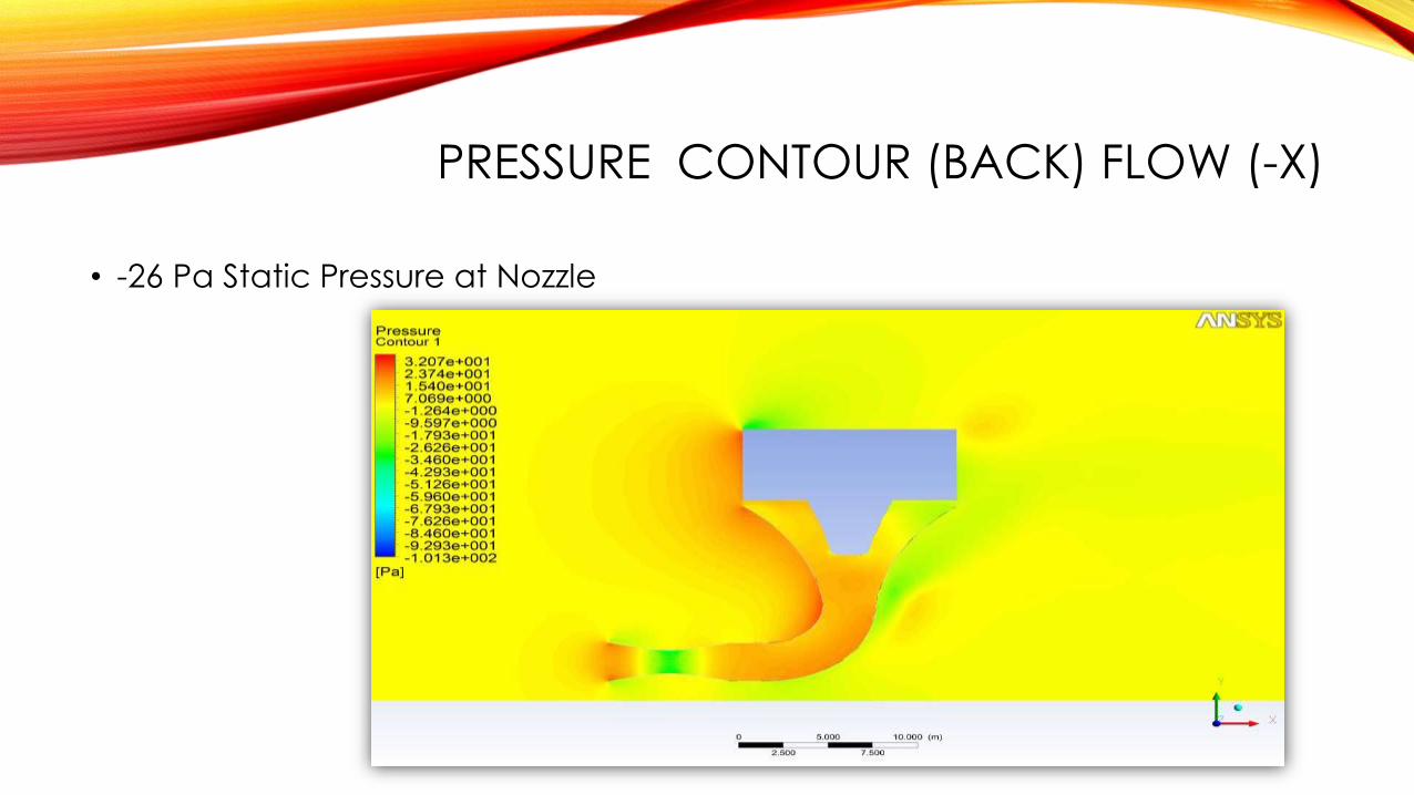
PRESSURE CONTOUR (BACK) FLOW (-X)
• -26 Pa Static Pressure at Nozzle

VELOCITY CONTOUR (–) X FLOW
• 9.8 m/s Velocity at Nozzle
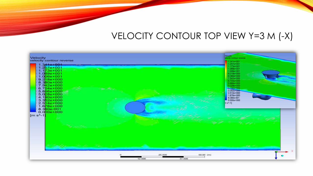
VELOCITY CONTOUR TOP VIEW Y=3 M (-X)
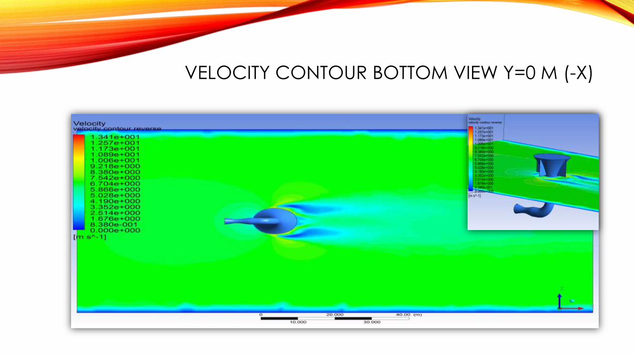
VELOCITY CONTOUR BOTTOM VIEW Y=0 M (-X)
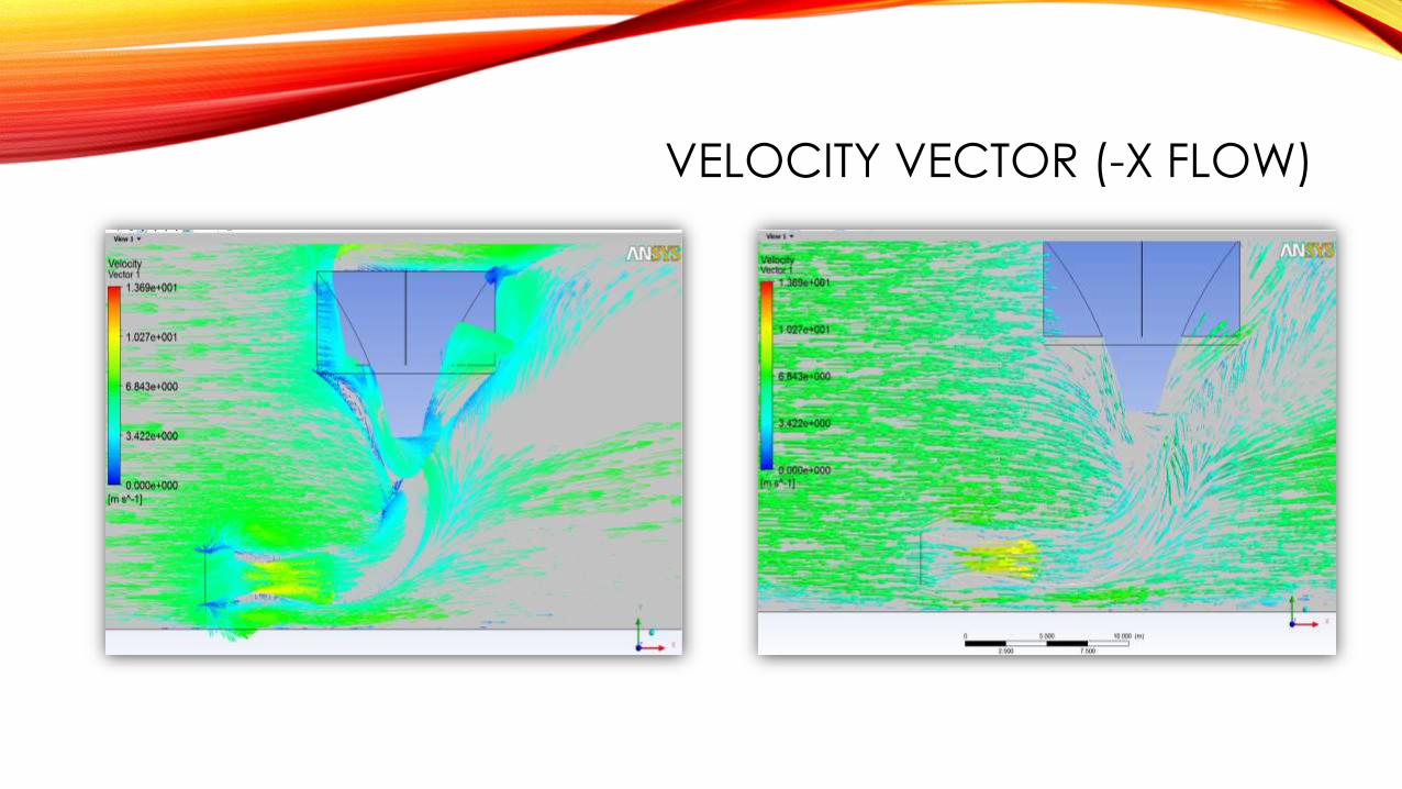
VELOCITY VECTOR (-X FLOW)
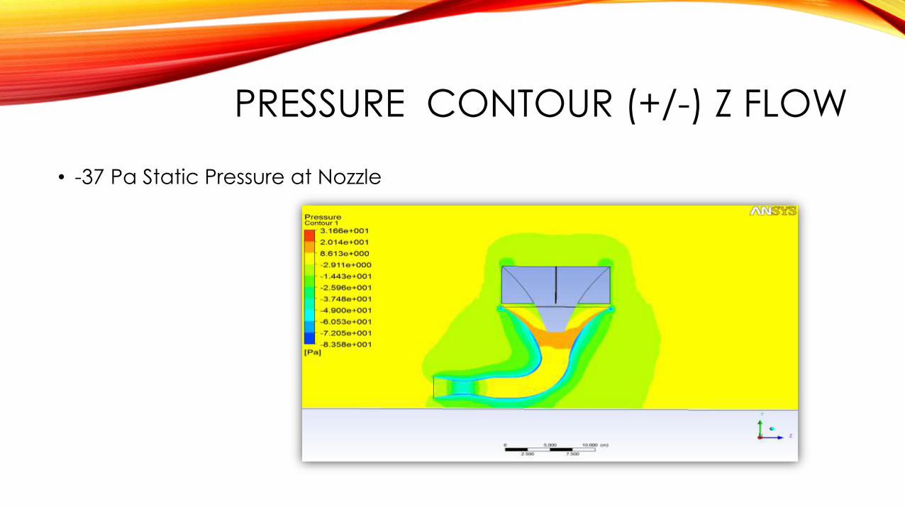
PRESSURE CONTOUR (+/-) Z FLOW
• -37 Pa Static Pressure at Nozzle
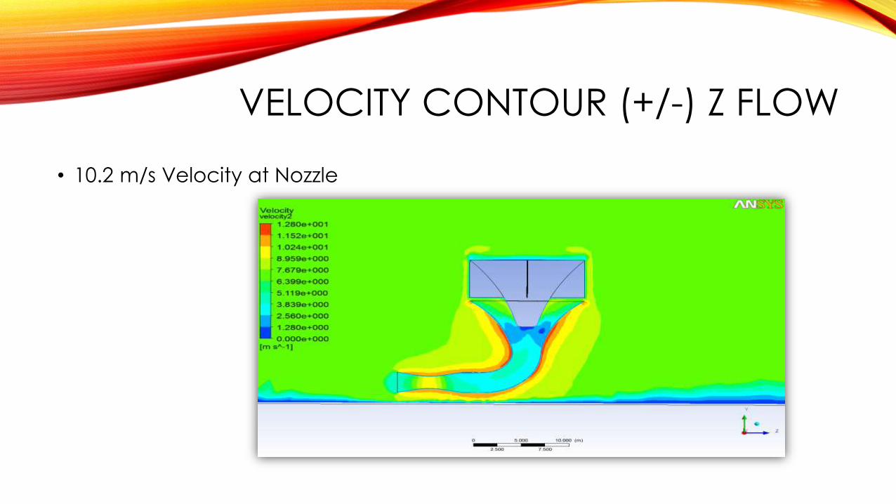
VELOCITY CONTOUR (+/-) Z FLOW
• 10.2 m/s Velocity at Nozzle
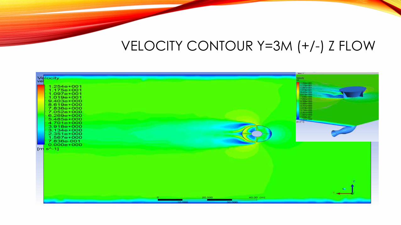
VELOCITY CONTOUR Y=3M (+/-) Z FLOW
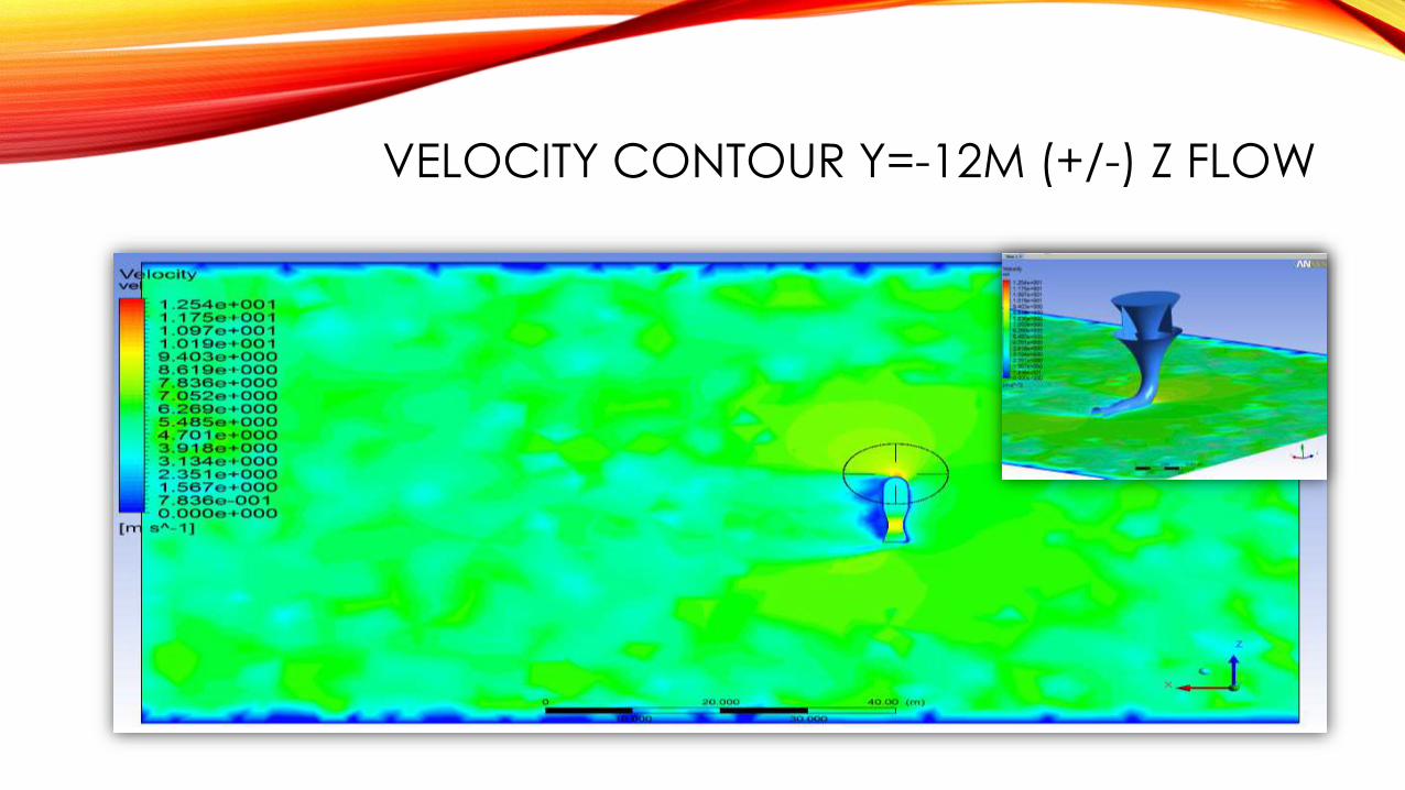
VELOCITY CONTOUR Y=-12M (+/-) Z FLOW

STREAM LINES 3D (+/-) Z FLOW
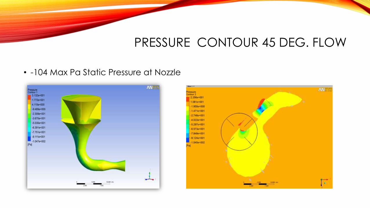
PRESSURE CONTOUR 45 DEG. FLOW
• -104 Max Pa Static Pressure at Nozzle
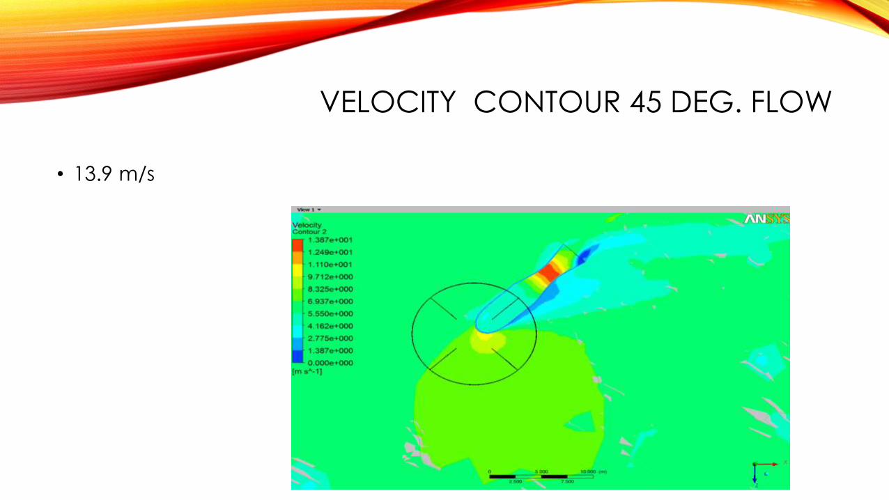
VELOCITY CONTOUR 45 DEG. FLOW
• 13.9 m/s
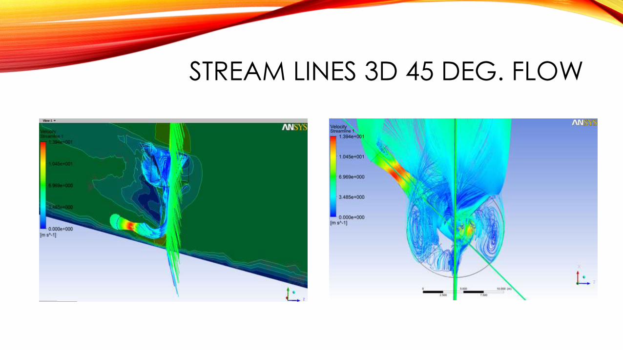
STREAM LINES 3D 45 DEG. FLOW
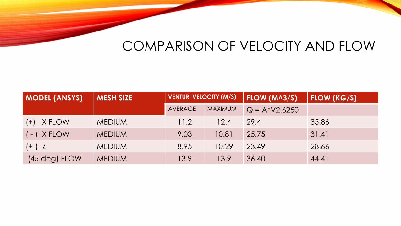
COMPARISON OF VELOCITY AND FLOW
MODEL (ANSYS) MESH SIZE VENTURI VELOCITY (M/S) FLOW (M^3/S) FLOW (KG/S)
AVERAGE MAXIMUM Q = A*V2.6250
(+) X FLOW MEDIUM 11.2 12.4 29.4 35.86
( - ) X FLOW MEDIUM 9.03 10.81 25.75 31.41
(+-) Z MEDIUM 8.95 10.29 23.49 28.66
(45 deg) FLOW MEDIUM 13.9 13.9 36.40 44.41
REFERENCES
• Prof.Y. Andreapolos, Dr. Daryoush Allaei Invelox “ A New Concept In Wind Energy Harvesting” ES-FuelCell2013-18311


![Tenure Dossier of Mehmet Gumus - McGill University...Mehmet Gumus Curriculum Vitae 4 of 19 [C3] Mohammad Nikoofal, and Mehmet Gumus.The Value of Audit in Managing Supplier’s Process](https://img.pdfslide.us/doc/110x75/5f47630bdde60c45626acc56/tenure-dossier-of-mehmet-gumus-mcgill-university-mehmet-gumus-curriculum-vitae.jpg)


![The Albanian Question - Mehmet Konitza [Mehmet Konica] (1818)](https://img.pdfslide.us/doc/110x75/55284d4f5503467f588b4727/the-albanian-question-mehmet-konitza-mehmet-konica-1818.jpg)