Embed Size (px)
Citation preview

OFFICE OF MATERIALS
STATE OF MINNESOTA DEPARTMENT OF HIGHWAYS
in cooperation with U.S. DEPARTMENT OF COMMERCE BUREAU OF PUBLIC ROADS and MINNESOTA LOCAL ROAD RESEARCH BOARD
FLEXIBLE PAVEMENTEVALUATION
WITH THEBENKELMAN BEAM
INVESTIGATION NO. 603 SUMMARY REPORT – 1968
(1983 Revision)
FLEXIBLE PAVEMENT EVALUATION WITH THE BENKELMAN BEAM
INVESTIGATION NO. 603 Summary Report - 1968
Prepared by
C. G. Kruse, Research Project Engineer Minnesota Highway Department
and
E. L. Skok, Jr.
University of Minnesota
Under the Direction and Supervision of
F. C. Fredrickson, Materials Engineer
P. A. Jensen, Research Engineer
OFFICE OF MATERIALS
MINNESOTA DEPARTMENT OF HIGHWAYS
in cooperation with
U. S. DEPARTMENT OF TRANSPORTATION FEDERAL HIGHWAY ADMINISTRATION
BUREAU OF PUBLIC ROADS
and
MINNESOTA LOCAL ROAD RESEARCH BOARD The opinions, findings and conclusions expressed in this publication are those of the authors and not necessarily those of the Bureau of Public Roads.
i
FOREWORD This report culminates one of the first projects undertaken for study in the Local Road Research Program. The primary purpose of this project when it was initiated was to develop a correlation between the plate bearing test and the Benkelman beam test. Such a correlation, or other acceptable procedure for using the Benkelman beam, would provide a practical and relatively economical means for our local highway engineers to obtain a measure of the strength (load carrying capacity) of flexible pavements. Data were obtained under this study during seven years of testing on roads in all counties in the state and on streets in many municipalities. A progress report, Load Carrying Capacity of Minnesota Secondary Flexible Pavements, was published in 1964 covering the data collected during the first three years of testing. During the past year the University of Minnesota, Department of Civil Engineering analyzed all of the data collected under this project and prepared the final report Load Carrying Capacity of Minnesota Secondary Flexible Pavements. Because the University report presented the data analysis in considerable detail, the Local Road Research Board felt that a shortened version of the report emphasizing the procedure for using the Benkelman beam would be more acceptable to the busy engineer. This report was prepared in accordance with the Board's recommendation and is divided into two parts. Part I presents a brief summary of the results, conclusions and recommendations of the University's report. Part II covers the Benkelman beam test procedure. It will serve as a guide to field personnel in conducting the test and determining the estimate of load carrying capacity from the deflection measurements. The Benkelman beam test can be a valuable aid to the engineer in providing a more objective basis for his determination of the requirements for reinforcing and upgrading flexible pavements, evaluating his flexible pavement designs, and in setting spring load restrictions. It is hoped that Minnesota engineers will take advantage of this research and implement a program of deflection measurements to aid them in making engineering decisions in which the strength of flexible pavements is a factor.

ii
ACKNOWLEDGMENTS
Sincere appreciation is expressed to the engineers of all 87 Minnesota counties and to the engineers of the many municipalities who participated in this research. Their continued interest in the study, and their cooperation in permitting testing on highways and streets under their jurisdiction and in supplying engineering data for the pavements tested, was essential to the conduct of the research. The authors acknowledge the work of the many personnel of the Research Section who worked on this investigation over the past eight years. In particular, appreciation is expressed to Robert E. Wolfe and Paul J. Diethelm former Research Project Engineers who supervised the work and to Research Assistant, John B. Reichel and John C. Hale, Jr. who supervised the field testing crews. Special thanks are due the engineering assistants at the University of Minnesota who worked on the analysis of the data for the final report.
iii
SUMMARY
Purpose
The purpose of this investigation was to determine the relationship between the Minnesota Quickie plate bearing test and the Benkelman beam test for predicting the allowable spring load, and to determine the relationship of the two test methods to load carrying capacity, pavement structure, and performance of county roads and municipal streets in Minnesota. Procedures
The study was begun in 1960. The field work consisted of conducting Minnesota Quickie plate bearing tests and Benkelman beam tests simultaneously for comparison. Soil borings were made to determine the thickness of the various pavement layers and the embankment type. Data analysis was performed largely by the Department of Civil Engineering, University of Minnesota, using a computer to perform multiple correlation analyses. Results
A mathematical correlation was developed between the Minnesota Quickie plate bearing test and the Benkelman beam test. However, the data scatter, or variance, is such that it cannot be recommended for use.
Correlations were also developed between the two test methods and pavement structures but again the data scatter is such that it cannot be recommended for use. A method for determining allowable spring deflection with the Benkelman beam was developed from a literature survey and from a closely related field study. Conclusions and Recommendations
It is a general conclusion of this investigation that the Benkelman beam can be a very effective tool for obtaining information which will be a valuable aid in making engineering decisions with respect to the strength of flexible pavements. It is recommended that Minnesota highway engineers strongly consider using a program of deflection measurements as an objective basis for evaluating the strength of their flexible pavements. The procedures to be followed for performing the Benkelman beam test and for estimating load carrying capacity are given in PART II of this report.
iv
TABLE OF CONTENTS
Page Foreword ..................................................................................................................................................... i Acknowledgments ...................................................................................................................................... ii Summary ................................................................................................................................................... iii Table of Contents ...................................................................................................................................... iv List of Figures.............................................................................................................................................v List of Tables ..............................................................................................................................................v Introduction.................................................................................................................................................1 PART I - Summary of Findings of Final Report - Investigation No. 603 ....................................................2
Benkelman Beam Vs. Plate Bearing Test ....................................................................................2
Spring Capacity From Benkelman Beam ......................................................................................3
Plate Bearing Test Vs. Pavement Component Thickness ..........................................................7
Benkelman Beam Test Vs. Pavement Thickness .......................................................................7
Benkelman Beam Vs. Performance ............................................................................................7
Recommendations.......................................................................................................................8
PART II - Testing Equipment and Operational Procedures for Benkelman Beam Deflection Tests ..............................................................................................................11
Equipment Requirements ..........................................................................................................11
Personnel Requirements ...........................................................................................................14
Testing Procedure .....................................................................................................................14
Estimated Spring Load-Carrying Capacity ................................................................................17
References ...............................................................................................................................................24
v
LIST OF FIGURES Figure Page 1. Seasonal variations in Benkelman beam deflections .........................................................................4 2. M.H.D. Benkelman beam .................................................................................................................12 3. Close-up of M.H.D. Benkelman ........................................................................................................12
LIST OF TABLES Table Page 1. Benkelman beam deflections correcteed to 80 ºF ............................................................................18
2. Deflection ratios to calculate maximum spring deflections taken during other non-frozen times of the year (1983 Revision) ...................................................19
3. Allowable spring deflections..............................................................................................................20
4. Benkelman beam deflections test results and conditions for 10-mile highway, 7 ton axle load ...............................................................................................22
5. Determinations of allowable spring axle load ...................................................................................23
1
INTRODUCTION
In recent years many counties and municipalities have been interested in road strength information
as an aid in establishing spring load restrictions and to some extent to evaluate their flexible pavement
design. The Minnesota Highway Department has used a plate bearing test for about 16 years for this
purpose. However, the cost of the plate bearing test is too great to make it practical for general use in
determining road strength. This investigation was initiated in 1960 to study the use of the Benkelman beam
as a practical means of evaluating road strength.
The objectives of this investigation were to determine the relationship between the Benkelman
beam and plate bearing tests for prediction of the allowable spring load, and the relationships of the two
tests to load carrying capacity, pavement structure, and pavement performance.
The field measurements for this study were obtained over a period of seven years by personnel of
the Research Section, Office of Materials. Tests were conducted in all counties of the state and in many
municipalities. Approximately 15,000 items of data were accumulated including a Minnesota Quickie plate
bearing value, five Benkelman beam deflections, pavement component thicknesses, embankment
classification, and pavement condition for each test section location. Analyses of these data were done by
the Civil Engineering Department of the University of Minnesota, using computerized statistical analysis
procedures. The results of the analysis are included in the final report published by the University and
entitled Load Carrying Capacity of Minnesota Secondary Flexible Pavements.
Part I of this report presents a brief summary of the findings, results and conclusions of the report
published by the University followed by recommendations for application of the Benkelman beam test and
utilization of the data.
Part II of this report presents the recommended testing procedures, equipment, and personnel
requirements for conducting the Benkelman beam test. Also given is the method for computing allowable
spring axle load from the test data.
2
PART I
SUMMARY OF FINDINGS of
FINAL REPORT - INVESTIGATION NO. 603
BENKELMAN BEAM VS. PLATE BEARING TEST
The first objective of this investigation was to determine the relationship between the Benkelman
beam test and the Minnesota Quickie plate bearing test. A correlation between the two tests was developed
early in the study and reported in the 1964 progress report. While there was a substantial scatter in the data
and the correlation was not considered entirely satisfactory, the report recommended a limited use of the
correlation for estimating allowable spring axle loads from beam deflection measurements for pavements on
plastic embankment soils. It was hoped that additional data and further analysis would improve the
correlation and permit a broader application of the Benkelman beam test for determining flexible pavement
strength.
The additional data collected since 1964 have been incorporated with the earlier data and are
reported in the final report. Unfortunately the additional data have resulted in a poorer correlation between
bearing value and Benkelman beam deflection than was reported in the 1964 progress report.
Considering all the data obtained in the plastic embankment category, the bearing value of a test
section as determined by the plate bearing test would, in 95 percent of the cases, be in a range having a low
limit of 0.70 and an upper limit of 1.44 times the bearing value predicted from the Benkelman beam
deflection. For instance, if the Benkelman beam deflection is 0.100 inches the predicted bearing value would
be 109 psi or 7 tons. However, at the 95 percent confidence level the bearing value of the section in
question, as determined by the plate test may be anywhere in the range of 0.70 x 7 tons to 1.44 x 7 tons or
4.9 tons to 10.1 tons. Likewise, for the non-plastic embankment category the plate bearing value would be in
a range having a lower limit of 0.76 and an upper limit of 1.32; at 7 tons a range of 5.3 tons to 9.2 tons.
These ranges would be larger yet in 5 percent of the cases.
3
The ranges shown on the previous page illustrate that plate bearing value cannot be predicted by
the Benkelman beam with a satisfactory degree of confidence.
SPRING CAPACITY FROM BENKELMAN BEAM
It was intended, when this study was originated, that the spring capacity of a road would be
determined by converting Benkelman beam test results to Minnesota Quickie plate bearing values using
correlation equations developed in this study. The spring capacity was then to be calculated by the
established plate bearing method. But, because of the data spread associated with the correlation equations
this procedure did not appear to be satisfactory and a second, direct method was developed.
The development of the direct method required the determination of three factors to make it possible
to determine the allowable spring axle load. These three factors are: (1) the seasonal variation of deflections
for various pavement sections, (2) the determination of allowable deflections for various pavement sections
and traffic counts, and (3) the relationship between the load and deflection for any particular highway
section.
Seasonal Variations of Deflections
The variations of pavement strength throughout the year have been studied with the Benkelman
beam each year since 1964. Spring recovery testing was done on eleven test sections in 1964 and 1965 and
on 15 test sections in 1966 and 1967. These test sections were generally low and medium strength
pavements on clayey embankment soils (two test sections were on a sand embankment soil). It, was
reasoned that these sections were typical of pavements which are restricted in the spring.
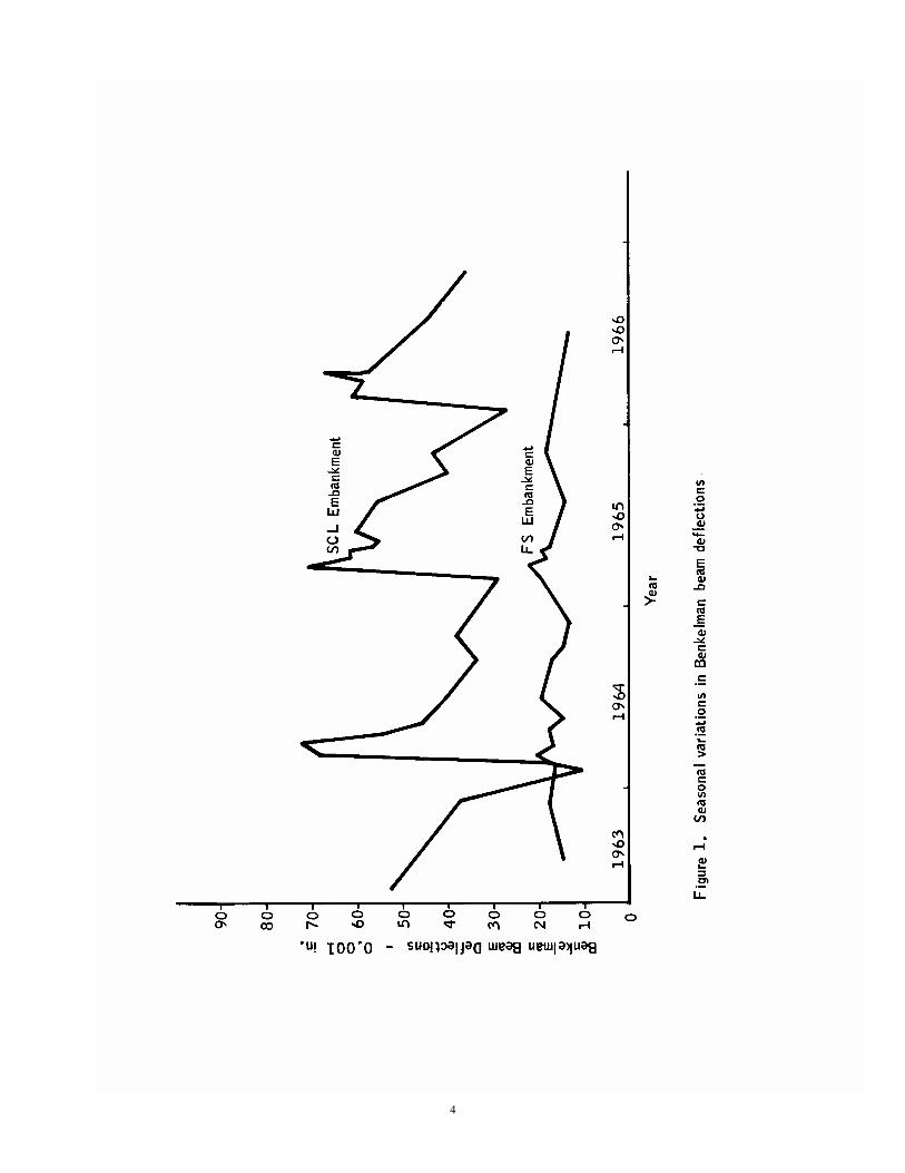
Figure 1 shows the variations of deflections throughout the years 1963 through 1966 for two test
sections. These test sections represent typical high and low variations which were observed during the
testing. From curves like this for all test sections and all years tested, relationships have been developed by
which a deflection test taken at any time of the year when the pavement is unfrozen can be used to estimate
the critical spring deflection. Variations also occur from year to year depending on the severity of the winter.
Severity depends on many factors
4
5
including moisture in the soil and degree days. Part II of this report gives deflection ratios to calculate
maximum spring deflections from deflections taken during other non-frozen times of the year. These ratios
are based on a winter slightly more severe than an average winter.
Determination of Allowable Deflections
To determine an allowable axle load by the direct method it is necessary to establish allowable
deflections which should be exceeded only a relatively few times in order for the pavement to perform
satisfactorily. Performance, as defined in this procedure, is based primarily on criteria used at the AASHO
Road Test. That is, with a design period of 20 years a pavement is considered to have performed
satisfactorily if at the end of 20 years its Present Serviceability Index has not dropped below a "terminal
index" of 2.5. If the allowable deflections have been accurately chosen and deflections which exceed the
allowable occur repeatedly the pavement will fail, or reach the terminal index, in something less than 20
years.
The allowable deflections which are recommended in the section on test procedures were developed
from considerations of results of Investigation 183, "Application of AASHO Road Test Results to Design of
Flexible Pavements in Minnesota"; results from the AASHO Road Test, and research done at the WASHO
Road Test, by the state of California, by the Canadian Good Roads Association, and by others. Since many
factors such as climate, type of aggregate, type of mix, etc., could influence the allowable deflections one of
the objectives of Investigation 183 is to verify the use of the recommended allowable deflections.
In general, the allowable deflections are dependent on the amount of traffic on the road and on the
thickness of the surface of the pavement section. If there are more heavy loads on a given pavement
structure it will fail faster due to fatigue. With a given deflection, and all other factors being equal, the
stresses in a thick asphalt layer will be greater and it will fail more rapidly than a thinner layer.
Load - Deflection Relationships
The third requirement for use of the Benkelman beam in directly determining the allowable spring
load is that the relationship between loads and deflections for any pavement section be known.
Studies of this relationship have been reported by the Canadian Good Road Association (CGRA) and from
the AASHO Road Test. Considering these reports and the theoretical relationships developed from
6
Boussinesq and Two-layer Elastic systems, it was decided that assuming a straight line relationship between
loads and deflections would be satisfactory. Thus, a proportional relationship such as:
where: L1 , L2 = axle loads, tons
d1 , d2 = Benkelman beam deflections, in. can be used. This allows computation of an expected deflection for any load once a deflection for a specific
load has been established.
Therefore, knowing the deflection caused by a certain test load at a given time, which is then
converted to a spring deflection for that load, and knowing the allowable deflection for the road in question
the allowable load can be calculated by the relationships given above. Complete procedures and an example
of the use of the Benkelman beam are given in Part II of this report.
The allowable loads arrived at by this method are conservative estimates of the loads which can be
sustained over the design period of 20 years. There are three reasons for this. First, the ratios used for
converting the test deflection to a spring deflection are based on a winter more severe than average. Thus, a
margin of safety is provided. Second, two standard deviations of the deflections are added to the average
deflection (see section titled ESTIMATING SPRING LOAD-CARRYING CAPACITY in Part II) to compensate
for the areas of the pavement that are weaker than average.
Third, the allowable deflections were set conservatively as a further margin of safety. As experience
is gained with this procedure the relationship between deflection and pavement performance will be better
defined and more accurate predictions of load carrying capacity should be possible.
2
2
1
1
dL
dL
=
7
PLATE BEARING TEST VS. PAVEMENT COMPONENT THICKNESS
The analysis of the relationship between spring tonnage, as determined by the Minnesota Quickie
plate bearing test, and pavement component thickness showed a poor correlation between these two
variables. General correlation lines were obtained but the data scatter was quite significant. Analyses were
first made dividing the test results into 16 embankment classifications. The test results were then regrouped
into three embankment classifications, plastic, semi-plastic, and non-plastic. The resulting correlations were
as good as using 16 classifications. All test results were converted to critical spring values to eliminate the
variation with time of year.
There are several possible sources of variation which were not accounted for in the statistical.
analysis and which may have caused the data scatter. First, since these tests were taken over a period of
years, there is a year to year variation which, although small, is one source. A second source is the variation.
in drainage characteristics of test sites which are otherwise similar. Probably the biggest source of error is
the variation of strength within a mat, base, subbase, or embankment classification. These strength
differences can be significant, particularly in the embankment classification. If has been shown (M. H. D.
Investigations 176 & 183) that there is a wide variation in strength for A-6 and also for A-4 soils.
BENKELMAN BEAM TEST VS. PAVEMENT THICKNESS
An attempt was made to correlate the Benkelman beam deflections, converted to maximum spring
deflections, with pavement section thicknesses and embankment types as was done for the plate bearing
test. The same classifications of embankment were found appropriate and correlation lines were developed.
Again, the data scatter was wide enough to prevent their being presented for use. The reasons for this are
thought to be the same as for the data scatter in the plate bearing vs. pavement thickness relationship.
BENKELMAN BEAM VS. PERFORMANCE
Justification of the use of the Benkelman beam directly, without correlation to the Minnesota Quickie
Plate Bearing test, must be based on its ability to predict pavement performance.
8
Since this investigation was initially intended to correlate the Benkelman beam with the plate bearing test,
the problem of predicting performance directly was not seriously studied in the field. However, this was
studied by a review of work done by other investigators and in Investigation No. 183.
Reports of work done by the state of California, the Canadian Goods Roads Association,
investigators at the AASHO Road Test, and others were studied to take advantage of their experience with
the Benkelman beam. In all cases the conclusion was that the Benkelman beam could be used to predict the
performance of pavements.
Their results and recommendations were applied to conditions in Minnesota by studying the 50 test
sections in Investigation No. 183 for the relationship between spring deflection and present pavement
conditions and comparing these results to those of the other investigators. Although Investigation No. 183
performance data have only been gathered since 1963, it was felt that the results were positive enough to
make the firm recommendations for the use of the Benkelman beam which are made in this report. Future
studies may result in some revisions, particularly in the area of allowable deflections, but it is expected that
any change will be minor.
RECOMMENDATIONS
It is a general conclusion of this investigation that the Benkelman beam can be a very effective tool
for obtaining information which will be a valuable aid in making engineering decisions with respect to the
strength of flexible pavements.
The principal application of the Benkelman beam is in obtaining a measure of the strength of flexible
pavements. This information can be used to add many -engineering decisions such as the establishment
and timing of spring load restrictions, comparison of the relative merits of an overlay versus reconstruction of
a weak pavement, and prediction of the useful life of a pavement. It can also be valuable in evaluating the
structural design of flexible pavements and when sufficient performance history has been accumulated it
may become a basis for design.
9
It is recommended that Minnesota highway engineers strongly consider using a program of
deflection measurements as an objective basis for evaluating the strength of their flexible pavements. It must
be emphasized, however, that beam deflections cannot be considered absolute criteria but rather that they
will provide additional information to aid the engineer in making certain decisions.
Predicting Allowable Spring Loads
Two methods of predicting allowable spring load on a pavement were considered in this study. The
method using the Benkelman beam deflections directly, without converting to plate bearing values, is the one
which is recommended for use.
There are two reasons for this. First, because of the possible errors which are introduced in the
conversion of deflections to plate bearing values the accuracy of this method becomes questionable.
Second, it is questionable that the plate bearing test gives an accurate allowable spring load by itself. The
plate bearing test was developed assuming an allowable deflection of 1/8 in., which may be acceptable for
certain types of pavement under certain traffic conditions. However, in view of recent research and
experience it is apparent that this magnitude of deflection is too severe for most pavements and traffic
conditions. The Benkelman beam method has the advantage of flexibility in setting the allowable deflections
depending upon the pavement and traffic considerations.
Timing Spring Load Restrictions
It should be possible to use the Benkelman beam test to establish more accurately the time when
the spring load restrictions should be imposed and lifted. This could be done by establishing a control
section on a relatively weak section of road and using it as an indicator of the loss of strength of pavements
in the area. It would be necessary to determine a deflection versus time curve for the section so that periods
of minimum strengths could be recognized and correlated with representative pavements.

10
Predicting Effect of Overlay
It is expected that within a period of one to two years it will be possible to predict the effect of an
overlay on deflections. The analysis of the Benkelman beam versus pavement component thicknesses
indicated that a certain percentage reduction in deflections could be expected with the addition of one inch of
bituminous surface. These factors have not been tested for use but this testing is being contemplated. When
these relationships have been established the Benkelman beam will be a valuable aid for determining a
required overlay thickness and also whether a pavement can be satisfactorily upgraded by an overlay or
whether reconstruction will be needed.
Determining General Level of Strength
With general use of the Benkelman beam throughout a municipality, county or district it will be
possible to accumulate a deflection history of all roads in the area under consideration. With the information
obtained from the AASHO Road Rest, its satellite studies, and other research it will eventually be possible to
use the deflection history as an important factor in the prediction of pavement life. This would, of course, be
of immense benefit in assessing the conditions of a system of roads and in programming for future needs.
11
PART II
TESTING EQUIPMENT AND OPERATIONAL PROCEDURES for
BENKELMAN BEAM DEFLECTION TESTS
The remainder of this report contains the information required to perform the Benkelman beam test.
It contains sections on equipment requirements, personnel requirements, testing procedures and
computations, and estimation of allowable spring loading. These sections which follow will serve as an
operating guide for field personnel.
EQUIPMENT REQUIREMENTS
Benkelman Beam
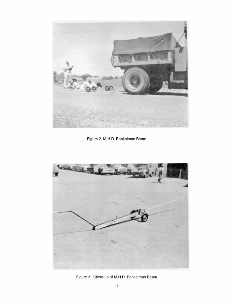
The Benkelman beam is a deflection-measuring device developed in 1953 by A.C. Benkelman of the
Bureau of Public Roads. See Figure 2. The instrument is basically a narrow beam with a probe foot that is
inserted between the dual tires of a load truck and rests on the pavement approximately two feet in front of
the axle. The probe beam is pivoted at a fulcrum point attached to a reference beam resting well back of the
influence of the load. Movement of the probe beam with respect to the reference beam is measured with an
indicating dial. In operation the load truck moves ahead at a creep speed and the total pavement deflection
between the dual tires as they pass the probe foot is read from the indicating dial.
Figure 3 shows a close up view of the Benkelman beam that is being used by the Minnesota
Highway Department. Although the design of this instrument may differ somewhat from that used by others
the basic dimensions and principles of operation are the same as those developed by Benkelman. The
probe beam is enclosed within the extruded tubing (reference beam) and pivots on ball bearings housed at
one end of the tube. The wheels are tipped or “released” from the beam by turning the handle near the wheel
assembly thus lowering the beam for testing. The probe beam is unlocked by releasing the pin near the dial
indicator freeing it for operation.
Accuracy of the beam should be checked occasionally. This is done by placing the beam on a solid
base such as a floor or pavement and placing shims of known thicknesses under the probe tip.
12
Figure 2. M.H.D. Benkelman Beam
Figure 3. Close-up of M.H.D. Benkelman Beam
13
With the beam free for operation, removal of the shim should result in a dial change of one-half of the shim
thickness. An automotive "feeler" gage works well as a shim. Lack of accuracy is generally due to
malfunction of the pivot bearings or dial indicator.
Load Truck
The vehicle used for testing should be a truck which can be loaded to the prescribed axle weight on
a single rear axle with dual tires. It is suggested that a 9-ton axle load be used. However, a 7-ton axle load
may be used during the critical spring period or on roads which are not normally subjected to 9-ton, traffic.
The load should be equally distributed between the two wheels, a deviation of up to 100 lb. per wheel is
permissible. The tires should be 12 ply, 10.00 x 20 tube type with rib treads, and inflated to a pressure of 70
psi. The tire pressure should be checked at frequent intervals.
Any material may be used as ballast when bringing the load truck up to the prescribed axle weight.
However, this material must not be susceptible to weight change due to inclement weather. The Research
Section has found plow cutting edges to be quite successful as ballast. The required number of cutting
edges were stacked to a desired height and secured in the truck bed to prevent shifting of load. A tarpaulin
was also fitted to the truck bed to exclude rain and snow and to conceal the ballast.
Miscellaneous Equipment
Other equipment necessary for conducting Benkelman beam tests are as follows: 1. A scale to check the load on the rear axle. Any scale known to be accurate which is capable of
weighing the rear axle separately will be satisfactory. it is also desirable to weigh one side of the
rear axle at a time to see that the load is centered. The weighing should include driver, tarp, and
1/2 tank of gasoline.
2. A tire pressure gage.
3. A thermometer with a temperature range of 0-220 °F with 2 °F divisions.
4. Spike or pointed reinforcing bar and hammer for driving hole in mat.
14
5. Oil can and oil (S.A.E. 30W).
6. Extra 6 volt lantern battery and buzzer.
7. Deflection dial gage - .001 in. smallest division.
8. Feeler gage for calibration (suggest two different thicknesses between 0.010 and 0.070 in.).
9. Signs, flags, etc. for traffic control.
10. Mobile auger or hand auger for soil borings at test site.
PERSONNEL REQUIREMENTS
The Benkelman beam crew consists of a crew chief (recorder), a beam operator, a truck driver, and
one or more flagmen for traffic control. It is possible for the crew chief to function also as the beam operator.
In order to complete the results obtained from the Benkelman beam it may be necessary to obtain a
soil survey of the road embankment soil. This would require a crew chief and an auger operator. It is not
necessary that the borings be taken at the time of the beam tests.
TESTING PROCEDURE
Test Site Location
In an effort to obtain measurements which are representative of each mile tested, it is suggested that
a minimum of ten test points per mile (one each 500 feet) be selected. If a road being considered for testing
is known to have differences in subgrade soils and/or pavement structure or has a history of certain problem
areas, additional test points may be desired to help define these areas and the possible strength differences
that may exist. Test points should not be selected in localized areas of alligatoring since such obvious
weakness would generally not be representative and the discontinuity of the bituminous surface may yield
deflections that are not meaningful. Each test point is tied in by stationing. If stationing cannot easily be as-
certained, the points should be tied in to each other with the odometer reading from a vehicle. The first and
last test points are usually tied in to a junction with a state or county highway. This and any other information,
such as prominent landmarks, that would be helpful in locating the individual points are recorded on a layout
sheet.
15
Testing is done in the outer wheel path because this is generally the weakest condition. The points are
located at specified distances from the edge of the pavement according to the width of the pavement as
follows:
Lane Width (ft.) Distance from Pavement Edge (ft.)
9 or less 1.5 10 2.0 11 1.5 12 or more 3.0
Marks can be painted along centerline opposite the test point in order to aid the truck driver in positioning the
load truck properly at each test point. A paint mark at the edge of the mat at each test point will help relocate
test points for future repeat tests.
Testing
The following is the procedure to be used for conducting the Benkelman beam test. It is important
that these procedures be followed closely.
1. Upon arrival at the test point set up traffic control.
2. Drive a hole in the pavement approximately 1/2 the thickness of the mat with the spike, fill it with
oil, and insert the bulb of the thermometer (This should be done at a minimum of one test point
in each mile).
3. Assemble Benkelman beam for testing.
4. Record mat temperature when temperature has stabilized.
5. With the aid of the marks painted along centerline the driver positions the truck so that the dual
wheels are centered over the test point.
6. The probe of the Benkelman beam is inserted between the dual wheels in the outer wheel path
with the foot of the probe placed approximately 2 ft. in front of the rear axle.
7. To lower the Benkelman beam release the wheel assembly by turning the handle at the front
end of the reference beam. Care should be taken to center the probe between the dual tires so
that the probe is not brushed by the tires as the truck moves forward.
8. Release the probe beam locking pin slowly to protect the dial from damage. Adjust the rear leg if
necessary so that the dial stem contacts the probe beam with sufficientamount of travel (not
usually necessary).
16
9. Turn the buzzer on and record the initial reading. It is not necessary to zero the dial. The
function of the buzzer is to create a small amount of vibration within the dial indicator to remove
the possibility of it sticking.
10. Signal the truck to move forward smoothly at creep speed (2-3 mph). Record the maximum dial
reading as the wheels pass the probe foot. The truck may proceed on to the next test point.
11. The final reading is recorded when the rate of recovery of the pavement is equal to or less than
0.001 in. per minute.
12. Turn the buzzer off and lock the probe beam with the locking pin before lifting the reference
beam to engage the wheel assembly. Failure to lock the beam before lifting may result in
damage to the dial gage.
13. Move to the next test point.
14. Compute individual deflections by subtracting the final reading from the maximum reading and
multiplying by 2 (lever arm ratio 2:1).
Site Information
In order to make the above data usable it is necessary to know the pavement section
thickness and class of embankment soil at each of the test points. If this information is not known,
borings should be taken to obtain it. These borings should be made in the outer wheel path to a
depth of 4 ft. From the borings it is necessary to note the mat thickness and depths and class of the
various soil layers.
Additional information that may prove valuable at a later date would be the condition of the
mat and the thickness of the gravel base and subbase. Information pertinent to surface condition
would be quantitative measurements of alligatoring, longitudinal and transverse cracking, wheel
tracking (rutting), recent seal coating, patching, etc. A structural rating system such as the one
developed in M.H.D. Inv. 189, Development of a Rating System to Determine the Need for
Pavement Resurfacing, could be used for this.
17
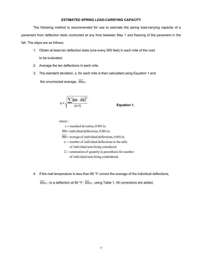
ESTIMATED SPRING LOAD-CARRYING CAPACITY
The following method is recommended for use to estimate the spring load-carrying capacity of a
pavement from deflection tests conducted at any time between May 1 and freezing of the pavement in the
fall. The steps are as follows:
1. Obtain at least ten deflection tests (one every 500 feet) in each mile of the road
to be evaluated.
2. Average the ten deflections in each mile.
3. The standard deviation, s, for each mile is then calculated using Equation 1 and
the uncorrected average, 80BB . Equation 1.
4. If the mat temperature is less than 80 °F correct the average of the individual deflections,
80BB , to a deflection at 80 °F, 80BB , using Table 1. All corrections are added.
( )( )1n-
BBBB=s
2∑ −
d.condsidere being testsindividual of numberfor sparenthesiin quantity ofsummation
.considered being testsindividual of mile. in the sdeflection individual ofnumber n in. 0.001 s,deflection individual of average BB
in. 0.001 s,deflection individual BB in. 0.001 deviation, standards
:where
=Σ
==
==
18
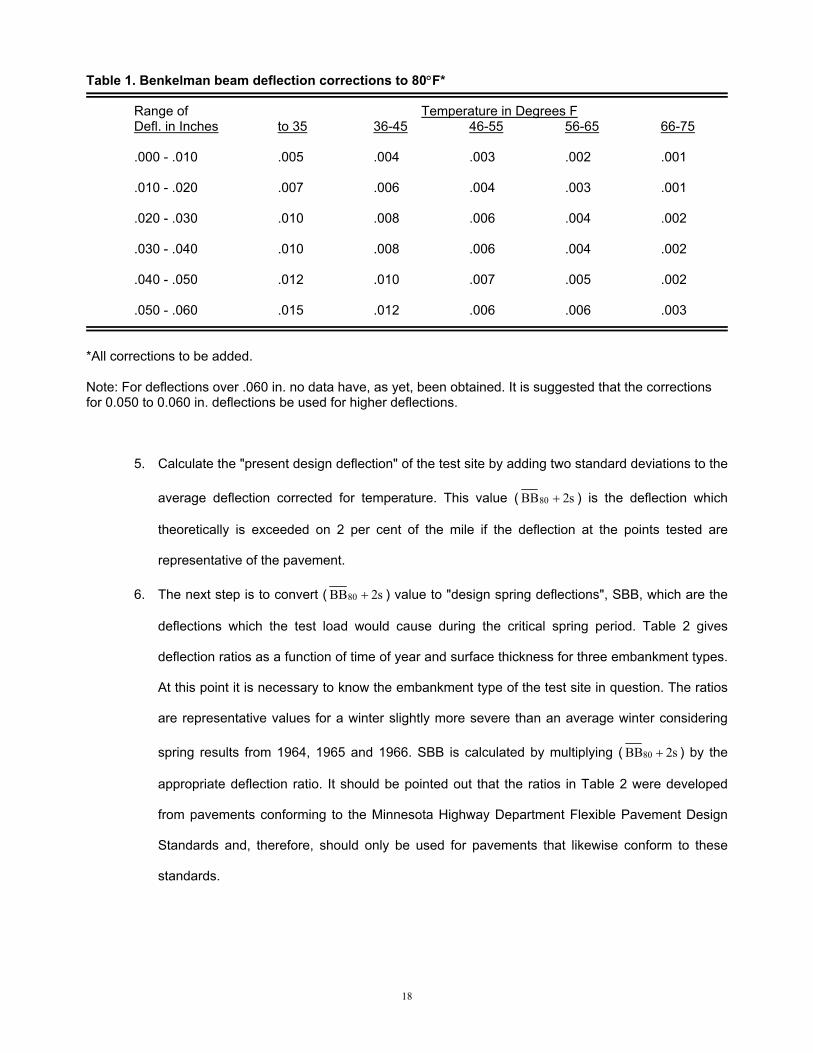
Table 1. Benkelman beam deflection corrections to 80°F* Range of Temperature in Degrees F Defl. in Inches to 35 36-45 46-55 56-65 66-75 .000 - .010 .005 .004 .003 .002 .001 .010 - .020 .007 .006 .004 .003 .001 .020 - .030 .010 .008 .006 .004 .002 .030 - .040 .010 .008 .006 .004 .002 .040 - .050 .012 .010 .007 .005 .002 .050 - .060 .015 .012 .006 .006 .003 *All corrections to be added. Note: For deflections over .060 in. no data have, as yet, been obtained. It is suggested that the corrections for 0.050 to 0.060 in. deflections be used for higher deflections.
5. Calculate the "present design deflection" of the test site by adding two standard deviations to the
average deflection corrected for temperature. This value ( s2BB80 + ) is the deflection which
theoretically is exceeded on 2 per cent of the mile if the deflection at the points tested are
representative of the pavement.
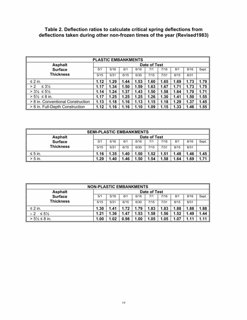
6. The next step is to convert ( s2BB80 + ) value to "design spring deflections", SBB, which are the
deflections which the test load would cause during the critical spring period. Table 2 gives
deflection ratios as a function of time of year and surface thickness for three embankment types.
At this point it is necessary to know the embankment type of the test site in question. The ratios
are representative values for a winter slightly more severe than an average winter considering
spring results from 1964, 1965 and 1966. SBB is calculated by multiplying ( s2BB80 + ) by the
appropriate deflection ratio. It should be pointed out that the ratios in Table 2 were developed
from pavements conforming to the Minnesota Highway Department Flexible Pavement Design
Standards and, therefore, should only be used for pavements that likewise conform to these
standards.
19
Table 2. Deflection ratios to calculate critical spring deflections from
deflections taken during other non-frozen times of the year (Revised1983)
PLASTIC EMBANKMENTS Date of Test
5/1 5/16 6/1 6/16 7/1 7/16 8/1 8/16 Sept. Asphalt Surface
Thickness 5/15 5/31 6/15 6/30 7/15 7/31 8/15 8/31 ≤ 2 in. 1.12 1.29 1.44 1.53 1.60 1.65 1.69 1.73 1.79 > 2 ≤ 3½ 1.17 1.34 1.50 1.59 1.63 1.67 1.71 1.73 1.75 > 3½ ≤ 5½ 1.14 1.24 1.37 1.43 1.50 1.58 1.64 1.70 1.71 > 5½ ≤ 8 in. 1.17 1.25 1.25 1.25 1.26 1.30 1.41 1.50 1.55 > 8 in. Conventional Construction 1.13 1.18 1.16 1.13 1.15 1.18 1.29 1.37 1.45 > 8 in. Full-Depth Construction 1.12 1.16 1.16 1.10 1.09 1.15 1.33 1.46 1.55
SEMI-PLASTIC EMBANKMENTS Date of Test
5/1 5/16 6/1 6/16 7/1 7/16 8/1 8/16 Sept. Asphalt Surface
Thickness 5/15 5/31 6/15 6/30 7/15 7/31 8/15 8/31 ≤ 5 in. 1.16 1.35 1.40 1.50 1.52 1.51 1.48 1.46 1.45 > 5 in. 1.29 1.40 1.46 1.50 1.54 1.58 1.64 1.69 1.71
NON-PLASTIC EMBANKMENTS Date of Test
5/1 5/16 6/1 6/16 7/1 7/16 8/1 8/16 Sept. Asphalt Surface
Thickness 5/15 5/31 6/15 6/30 7/15 7/31 8/15 8/31 ≤ 2 in. 1.30 1.41 1.72 1.79 1.83 1.83 1.88 1.88 1.88 > 2 ≤ 5½ 1.21 1.36 1.47 1.53 1.58 1.56 1.52 1.49 1.44 > 5½ ≤ 8 in. 1.00 1.02 0.98 1.00 1.05 1.05 1.07 1.11 1.11
20
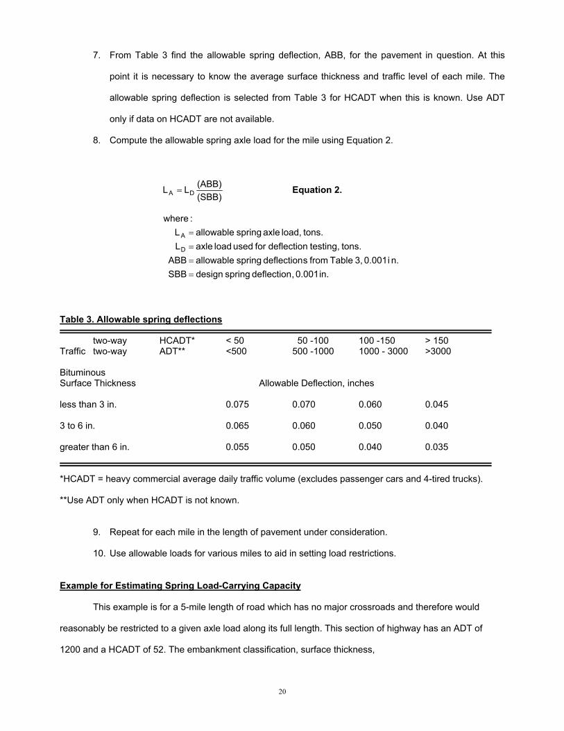
7. From Table 3 find the allowable spring deflection, ABB, for the pavement in question. At this
point it is necessary to know the average surface thickness and traffic level of each mile. The
allowable spring deflection is selected from Table 3 for HCADT when this is known. Use ADT
only if data on HCADT are not available.
8. Compute the allowable spring axle load for the mile using Equation 2.
(SBB)(ABB)LL DA = Equation 2.
Table 3. Allowable spring deflections two-way HCADT* < 50 50 -100 100 -150 > 150 Traffic two-way ADT** <500 500 -1000 1000 - 3000 >3000 Bituminous Surface Thickness Allowable Deflection, inches less than 3 in. 0.075 0.070 0.060 0.045 3 to 6 in. 0.065 0.060 0.050 0.040 greater than 6 in. 0.055 0.050 0.040 0.035 *HCADT = heavy commercial average daily traffic volume (excludes passenger cars and 4-tired trucks). **Use ADT only when HCADT is not known.
9. Repeat for each mile in the length of pavement under consideration.
10. Use allowable loads for various miles to aid in setting load restrictions.
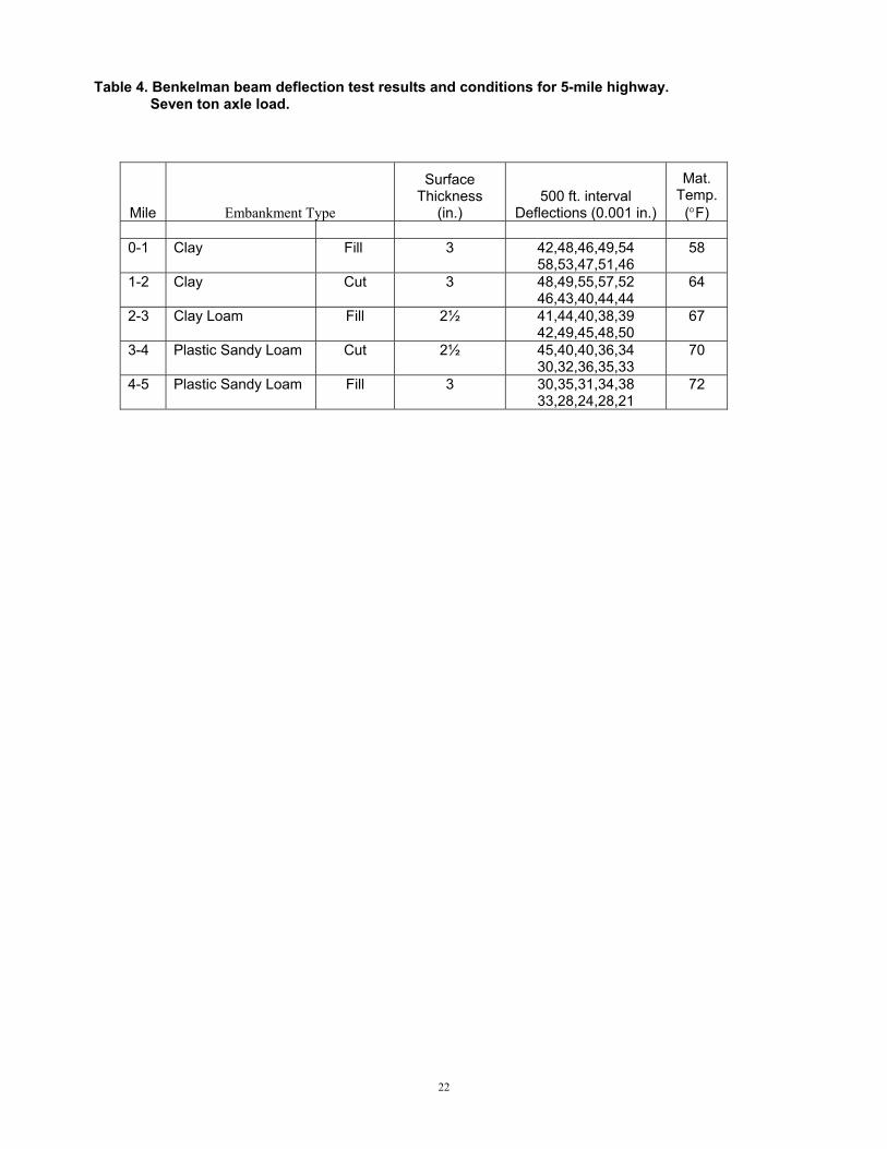
Example for Estimating Spring Load-Carrying Capacity
This example is for a 5-mile length of road which has no major crossroads and therefore would
reasonably be restricted to a given axle load along its full length. This section of highway has an ADT of
1200 and a HCADT of 52. The embankment classification, surface thickness,
in. 0.001 ,deflection spring design SBB n. i 0.001 3, Table from sdeflection spring allowable ABB
tons. testing, deflection for used load axle L tons. load, axle spring allowable L
:where
D
A
====

21
deflections, and mat temperatures for each mile are given in Table 4. A 7-ton axle load was used for the
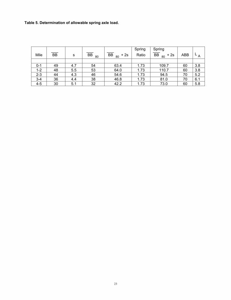
deflection testing. In Table 5 the allowable spring axle load determination is summarized. The procedures
are outlined here for mile 0-1.
1. Ten individual deflection tests are run 500 ft. apart within each mile. Soil borings are made if necessary.
2. The individual deflections are averaged:
10494
1046514753585449464842BB =
+++++++++=
inchanofsthousandth49=
3. The standard deviation is calculated using Equation 1:
4. The temperature correction is made to the average deflection. According to Table 1 this is 5
thousandths of an inch for 58 °F and an average deflection of 49.
inchanofsthousandth545495BBBB80 =+=+=
5. The present design deflection was calculated as follows:
63.44.7)(2542sBB80 =×+=+
6. The present design deflection was multiplied by the deflection ratio from Table 2 for a 3 in.
surface tested August 20 to get the design spring deflection, SBB.
inchanofsthousandth7.1094.63x73.1SBB ==
7. From Table 3 the allowable spring deflection was found for a HCADT of 52 and a surface thickness of 3 in., ABB = 60 thousandths of an inch.
8. The allowable axle load for this test section was calculated using Equation 2.
tons8.311060tons7
SBBABBLL DA =×=×=
9. In the same way the allowable axle loads were calculated for the successive test sections.
( ) ( ) ( ) ( ) ( )
( )
inch an of sthousandth 4.7
229
909149
11049464949494649482942s
212
1
21
22222
=
=⎥⎦⎤
⎢⎣⎡ +++++
=
⎥⎥⎦
⎤
⎢⎢⎣
⎡
−−++−+−+−+−
=
K
K
22
Table 4. Benkelman beam deflection test results and conditions for 5-mile highway. Seven ton axle load.
Mile Embankment Type
Surface Thickness
(in.) 500 ft. interval
Deflections (0.001 in.)
Mat. Temp.
(°F) 0-1 Clay Fill 3 42,48,46,49,54
58,53,47,51,46 58
1-2 Clay Cut 3 48,49,55,57,52 46,43,40,44,44
64
2-3 Clay Loam Fill 2½ 41,44,40,38,39 42,49,45,48,50
67
3-4 Plastic Sandy Loam Cut 2½ 45,40,40,36,34 30,32,36,35,33
70
4-5 Plastic Sandy Loam Fill 3 30,35,31,34,38 33,28,24,28,21
72
23
Table 5. Determination of allowable spring axle load.
Spring Spring Mile BB s BB 80 BB 80 + 2s Ratio BB 80 + 2s ABB L A
0-1 49 4.7 54 63.4 1.73 109.7 60 3.8 1-2 48 5.5 53 64.0 1.73 110.7 60 3.8 2-3 44 4.3 46 54.6 1.73 94.5 70 5.2 3-4 36 4.4 38 46.8 1.73 81.0 70 6.1 4-5 30 5.1 32 42.2 1.73 73.0 60 5.8
24
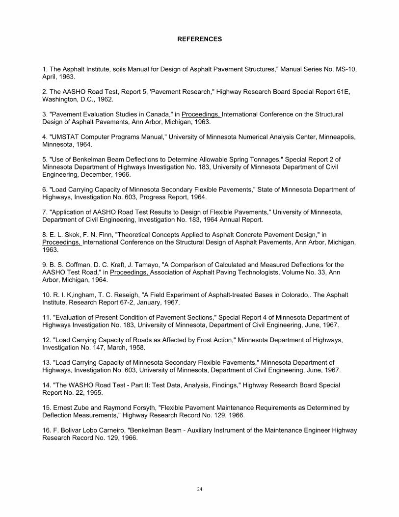
REFERENCES 1. The Asphalt Institute, soils Manual for Design of Asphalt Pavement Structures," Manual Series No. MS-10, April, 1963. 2. The AASHO Road Test, Report 5, 'Pavement Research," Highway Research Board Special Report 61E, Washington, D.C., 1962. 3. "Pavement Evaluation Studies in Canada," in Proceedings, International Conference on the Structural Design of Asphalt Pavements, Ann Arbor, Michigan, 1963. 4. "UMSTAT Computer Programs Manual," University of Minnesota Numerical Analysis Center, Minneapolis, Minnesota, 1964. 5. "Use of Benkelman Beam Deflections to Determine Allowable Spring Tonnages," Special Report 2 of Minnesota Department of Highways Investigation No. 183, University of Minnesota Department of Civil Engineering, December, 1966. 6. "Load Carrying Capacity of Minnesota Secondary Flexible Pavements," State of Minnesota Department of Highways, Investigation No. 603, Progress Report, 1964. 7. "Application of AASHO Road Test Results to Design of Flexible Pavements," University of Minnesota, Department of Civil Engineering, Investigation No. 183, 1964 Annual Report. 8. E. L. Skok, F. N. Finn, "Theoretical Concepts Applied to Asphalt Concrete Pavement Design," in Proceedings, International Conference on the Structural Design of Asphalt Pavements, Ann Arbor, Michigan, 1963. 9. B. S. Coffman, D. C. Kraft, J. Tamayo, "A Comparison of Calculated and Measured Deflections for the AASHO Test Road," in Proceedings, Association of Asphalt Paving Technologists, Volume No. 33, Ann Arbor, Michigan, 1964. 10. R. I. K,ingham, T. C. Reseigh, "A Field Experiment of Asphalt-treated Bases in Colorado,. The Asphalt Institute, Research Report 67-2, January, 1967. 11. "Evaluation of Present Condition of Pavement Sections," Special Report 4 of Minnesota Department of Highways Investigation No. 183, University of Minnesota, Department of Civil Engineering, June, 1967. 12. "Load Carrying Capacity of Roads as Affected by Frost Action," Minnesota Department of Highways, Investigation No. 147, March, 1958. 13. "Load Carrying Capacity of Minnesota Secondary Flexible Pavements," Minnesota Department of Highways, Investigation No. 603, University of Minnesota, Department of Civil Engineering, June, 1967. 14. "The WASHO Road Test - Part II: Test Data, Analysis, Findings," Highway Research Board Special Report No. 22, 1955. 15. Ernest Zube and Raymond Forsyth, "Flexible Pavement Maintenance Requirements as Determined by Deflection Measurements," Highway Research Record No. 129, 1966. 16. F. Bolivar Lobo Carneiro, "Benkelman Beam - Auxiliary Instrument of the Maintenance Engineer Highway Research Record No. 129, 1966.