Embed Size (px)
Citation preview

Compact InLine Water Separation at ATP oil & gas
(UK) Ltd Kilmar Platform – Southern North Sea
INTSOK Brownfield Seminar, 17th September 2015
Arno Vissers, FMC Technologies

Separation Systems9/11/2015 2Separation Systems9/11/2015 2
Outline
• InLine separation– Introduction
– InLine building blocks
– Technology Maturity
• ATP(UK) Kilmar: – Background & challenges
– Proposed solution
– Illustrations
– Operational experience

Separation Systems9/11/2015 3Separation Systems9/11/2015 3 3
Compact cyclonic separation vs. conventional vessel separation
• Stokes
d
dcs
s
gdv
µ
ρρ
18
*2
−=
• Swirling flow � enhanced gravity
g
aG =

Separation Systems9/11/2015 4Separation Systems9/11/2015 4
InLine separation – Compact technology
• Swirl element � G-force generated
• 1G vs. G > 100
Swirling flow

Separation Systems9/11/2015 5Separation Systems9/11/2015 5
DeLiquidiser
Separating liquid
from gas
DeWaterer
Separating water
from feed stream DeSanderSeparating sand
from feed stream
PhaseSplitter
Separating gas
from liquid
InLine building blocks
Benefits
• Increased production
• Low hydrocarbon inventory
• Design in accordance with piping code
• Reduced operating weight
• Small footprint

Separation Systems9/11/2015 6Separation Systems9/11/2015 6
Example: InLine PhaseSplitter (bulk gas/liquid
separation)
• Swirl element generates G-force
• Gas moves to the centre of the
tube, liquid to the outside
• Gas removed via central pick-up
tube
Separation Systems9/11/2015 7Separation Systems9/11/2015 7
InLine DeLiquidiser
• Compact Gas/Liquid Separation
• Typically for low liquid loadings,
LVF < 10%
• Integrated 2 stage separation:
– Liquid from gas removal in
cyclonic section
– Gas from liquid removal in
gravitational boot section
• Typical pressure drop < 1 bar

Separation Systems9/11/2015 8Separation Systems9/11/2015 8
InLine DeWaterer
• Compact Oil/Water Separation
• Typically for high water cuts, WC
> 50%
• Different reject sizes for water
removal 80-98%
• Relative low DP. Typically 1 bar
over the underflow.
• Typical water quality 100 - 1000
ppm OiW

Separation Systems9/11/2015 9Separation Systems9/11/2015 9
InLine HydroCyclone
• Compact water polishing
• Typically for low oil
concentrations, OiW < 10,000
ppm
• Relative high DP. Typically 3 bar
over the underflow.
• Cut-off size ~10-15 micron
• Typical efficiency ~95-99%
dPreject
dPunderflow
Separation Systems9/11/2015 10
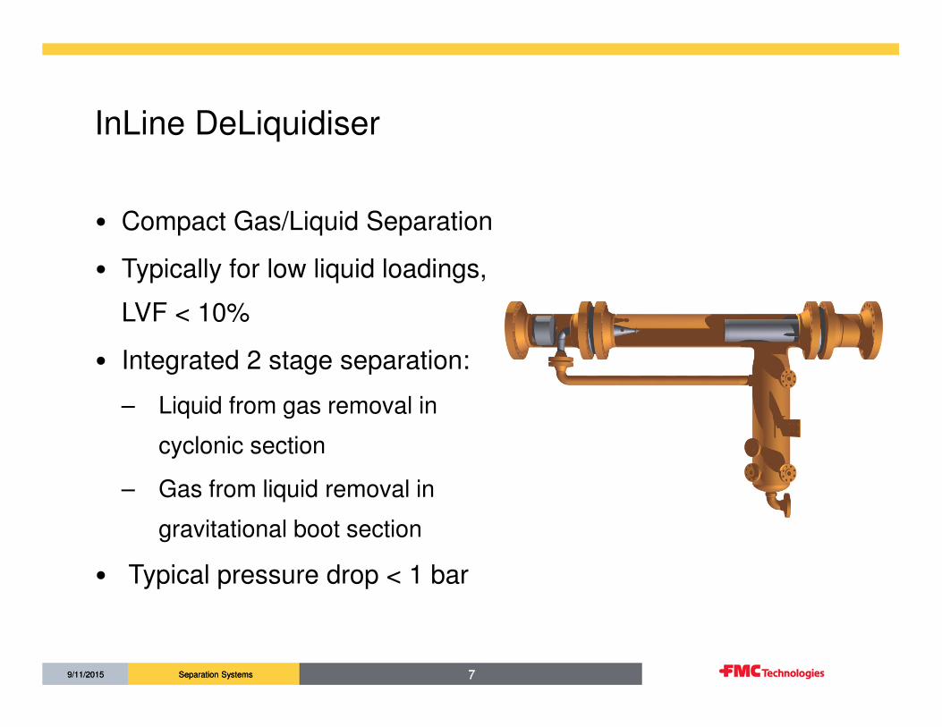
TECHNOLOGY MATURITY ASSESSMENT &
TECHNOLOGY READINESS
Technology Maturity Assessment considering:• Basic principles• General sizing considerations• Limitations• Development and qualification process• Field references
Technology Readiness Levels - Assigned rankings by Statoil & Petrobras

Separation Systems9/11/2015 11Separation Systems9/11/2015 11
ATP(UK) Kilmar: background & challenges
• The Kilmar platform is a not normally manned platform with
three producing wells (K1, K2, and K3).
• Kilmar wells are produced and co-mingled with Garrow wells,
sent to host platform for further processing
• Host platform: removal of water and condensate; gas
compressed and condensate re-combined for export to
onshore reception facilities.
Kilmar platform

Separation Systems9/11/2015 12Separation Systems9/11/2015 12
ATP(UK) Kilmar: problem & solution
Problem description:
• Host facility has limited water handling capacity
• K3 well is a high water producing well
• Limited space & lifting equipment on the platform
Solution:
• Pre-processing using compact InLine separation technology for K3 well:
– Separate the liquids from gas
– Separate oil from water
– Recombine the rejects with the main gas export line
• Discharge produced water at platform;
• Measurement of Oil-in-water concentration and produced water discharge rate.
Separation Systems9/11/2015 13Separation Systems9/11/2015 13
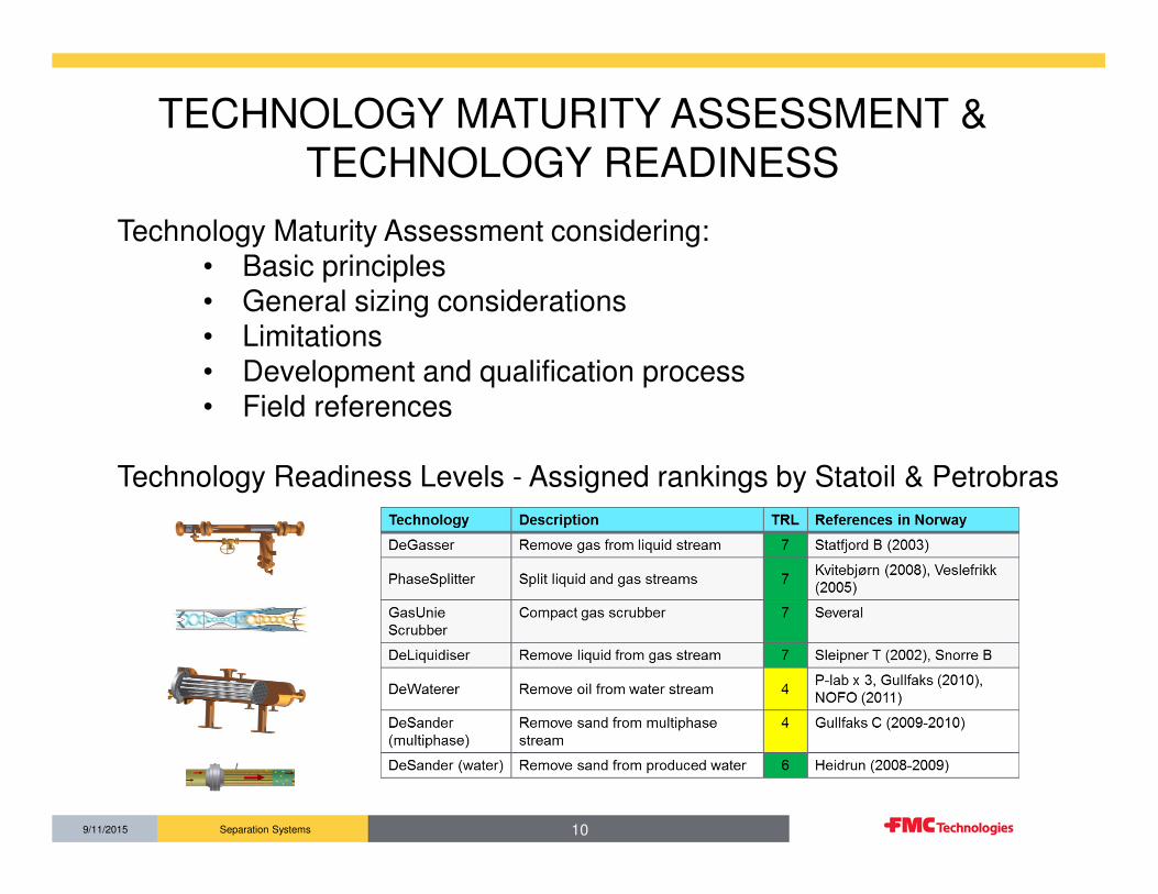
K3 well production profile
Time (years)

Separation Systems9/11/2015 14Separation Systems9/11/2015 14
K3 fluid properties & design conditions
• Liquid loading: 3-5% LVF
• Oil-in-water concentration: ~1% (= 10,000 mg/l)
• Gas flow rate: 15 – 3 MMSCFD
• Operating pressure: ~22 barg
• Material & pressure class: Duplex, 1500#
• OiW discharge requirement: < 30 mg/l

Separation Systems9/11/2015 1515Separation Systems9/11/2015
ATP(UK) Kilmar: PFD
InLine DeWaterer:Bulk Oil/Water separator
InLine HydroCyclone:Designed criterion reduce OiW to below
30 ppm
InLine DeLiquidiser:Compact Gas/Liquid separator
Note: degassing vessel not shown

Separation Systems9/11/2015 1616Separation Systems9/11/2015
ATP(UK) Kilmar: InLine Separation skid
• 6’’ DeLiquidiser with a
20’’ boot
• 1x6’’ DeWaterer
• 8x2’’ HydroCyclones
InLine DeWaterer
InLine DeLiquidiser
InLine HydroCyclone
Additionally:
• Vertical degassing
vessel
• Vent flare boom &
pipework added to
platform
• Control system Skid Dimensions: 3m x 3m x 2.2 m (H) -10000 kg (empty)
Kilmar InLine Separation Skid

Separation Systems9/11/2015 17
Oil bucket
level gauge
ATP(UK) Kilmar: degasssing vessel
Degasser
liquid level
gauge
Dimensions: 1.3m ID x 1.7 m T/T

Separation Systems9/11/2015 18
OIW meter unit housingOIW probe assembly
PW flowmeter sensors PW discharge pipework
PW discharge control valve
PW discharge ESD valve
ATP(UK) Kilmar: discharge section

Separation Systems9/11/2015 1919Separation Systems9/11/2015
Operational experience 2012/2013
• Commissioned end 2012:– More transient/slug flow than expected/designed for– Valve settings really important!– Tests run with certain valves in manual position
• Operational experience in 2013:– ATP’s plan was to flow K3 well through skid initially at 85
barg FTHP for a period of time to establish WGR at that rate; then step down to 30barg FTHP in stages, establishing the WGR at each stage
– Operational issues with host platform and onshore facilities have restricted opportunities to flow through the skid
– When restarting the skid, often issues with valves getting stuck. They often require manual reset.
– Test results November 2013:
• Gas rate ~ 10 MMSCFD;
• Liquid rate ~ 200 m3/d• OiW discharge 1-7 mg/l (requirement < 30 mg/l)

Separation Systems9/11/2015 2020Separation Systems9/11/2015
Operational data November 2013

Separation Systems9/11/2015 21Separation Systems9/11/2015 21
Conclusion
A compact partial processing skid has been applied successfully at the ATP(UK) Kilmar platform
Thank you for your attention!