Embed Size (px)
Citation preview

Intrusion Resilient and Real-Time Forensics
by
Tong Liu
A dissertation submitted to the Graduate Faculty ofAuburn University
in partial fulfillment of therequirements for the Degree of
Doctor of Philosophy
Auburn, AlabamaDecember 12, 2011
Keywords: Authentication, Network Security, Intrusion Resilience, Denial of Service,Correlation Engine, Real-Time Forensics
Copyright 2011 by Tong Liu
Approved by
Prathima Agrawal, Chair, Samuel Ginn Distinguished Professor of Electrical andComputer Engineering
Shiwen Mao, Associate Professor of Electrical and Computer EngineeringDarrel Hankerson, Professor of Mathematics and Statistics

Abstract
Intrusion to corporate network and unauthorized access to sensitive information can
cause huge damage and intellectual property loss. In addition to intrusion, Denial of service
(DoS)/Distributed DoS (DDoS) attack is also an eminent threat to an authentication server,
which is used to guard access to firewalls, virtual private networks and resources connected
by wired/wireless networks. Currently, most of the work has focused either on Intrusion
Detection Systems (IDS)/Intrusion Prevention Systems (IPS), Anti-Malware, Network Ac-
cess Control (NAC)/Network Access Protection (NAP), Firewall, or their combinations.
However, either one has some weaknesses and cannot protect the network against intru-
sion thoroughly. In this dissertation, we proposed two security systems to protect network
infrastructure against intrusion and data theft The first approach adopts distributing two-
factor user secrets and authentication servers. A queueing model is utilized to analyze the
performance of the proposed system. We also propose another innovative space-time evolv-
ing authentication scheme that includes users, processes, parent processes, applications and
behaviors, as well as guarded information resources. This systems oriented methodology em-
ploys security agents to proactively acquire and guard logs, and reconstruct the space-time
events of logs. A violation of ACL triggers a correlation engine to trace back related events
in real-time to identify the attack, the attacker and the damage, including lost information in
servers, hosts and devices. To test the performance, we first develop the system model, which
includes Client, Security Agent, Super Security Agent, Authentication Server, and Database
Server, using Java with JDK 1.6 against SQL injection attack and cross-site scripting attack.
Later on, we simulate the system with Matlab and OPNET in large scale. The simulation
results suggest that our proposed schemes are fast and effective against intrusion and data
theft.
ii

Acknowledgments
It is my great pleasure to express my appreciation for those who made this dissertation
possible.
There are a lot of people I would like to thank throughout the long journey of my
Ph.D. study. But first and foremost, I am heartily thankful to Dr. Prathima Agrawal,
and Dr. Mark Nelms, chair of the Department of Electrical and Computer Engineering.
Dr. Agrawal’s continuous encouragement, guidance and support enabled me to complete
this Ph.D. dissertation. Under her supervision, I learned how to do good research, how to
present your ideas, and how to write technical papers. While Dr. Nelms’s financial support
and encouragement helped me to finish my Ph.D. study without interruption. Without
them, it would have been impossible for me to finish this dissertation. Also, I would like to
thank Dr. Chwan-Hwa Wu, who supervised me on how to do good research and how to be
a good person during the first few years at Auburn.
I would gratefully thank my dissertation committee members, Dr. Shiwen Mao and
Dr. Darrel Hankerson, who gave me valuable advice not only for this dissertation, but also
during my entire Ph.D. program at Auburn University. My friendship with Dr. Mao dates
back to 2006 when I first came to Auburn, whose amiability and patience impressed me.
I took Dr. Mao’s Principle of Network Performance Analysis course in spring 2007 and
Telecommunication Networks course in fall 2007. Through these classes, I learned plenty of
knowledge about basic communication networks and advanced network performance analysis
technology. Dr. Mao also gave valuable suggestions on research and paper writing, as well as
personal life and job hunting. I met Dr. Darrel Hankerson during my first year at Auburn,
and later took his Cryptography class in spring 2007. Not only is Dr. Hankerson a great
iii

professor and researcher in Mathematics, but also is an excellent engineer. His rigorousness
and systems approach influenced me throughout the whole process of my Ph.D. study.
I also gratefully thank Dr. Xiao Qin from the Department of Computer Science and
Software Engineering for serving as the outside reader, reading my dissertation and picking
a time slot from his busy schedule to join my dissertation defense. In Dr. Qin’s Advanced
Computer and Network Security class, I learned not only advanced security knowledge, but
also how to do research and write technical papers.
The last but not the least, my deepest gratitude goes to my family, my beloved wife Lina
Cui, my lovely kids Caroline and Lawrence, my mother Zhenqin Sun, my parents-in-law, and
my sisters and brothers for their years of selfless support and unconditional love.
iv

Table of Contents
Abstract . . . . . . . . . . . . . . . . . . . . . . . . . . . . . . . . . . . . . . . . . . . ii
Acknowledgments . . . . . . . . . . . . . . . . . . . . . . . . . . . . . . . . . . . . . . iii
List of Figures . . . . . . . . . . . . . . . . . . . . . . . . . . . . . . . . . . . . . . . viii
List of Tables . . . . . . . . . . . . . . . . . . . . . . . . . . . . . . . . . . . . . . . . x
1 Introduction . . . . . . . . . . . . . . . . . . . . . . . . . . . . . . . . . . . . . . 1
1.1 Challenges for Network Authentication Protocols . . . . . . . . . . . . . . . 2
1.2 Challenges for Intrusion Resilience and Real-Time Forensics . . . . . . . . . 3
1.3 Motivation for Proposed Intrusion Resilient System . . . . . . . . . . . . . . 4
1.4 Motivation for Proposed Space-Time Authentication Scheme . . . . . . . . . 6
1.5 Dissertation Organization . . . . . . . . . . . . . . . . . . . . . . . . . . . . 7
2 Related Work . . . . . . . . . . . . . . . . . . . . . . . . . . . . . . . . . . . . . 9
2.1 Related Work on Authentication . . . . . . . . . . . . . . . . . . . . . . . . . 9
2.2 Related Work on DoS/DDoS . . . . . . . . . . . . . . . . . . . . . . . . . . . 10
2.3 Related Work on Intrusion Detection and Prevention . . . . . . . . . . . . . 12
2.4 Related Work on Forensics Correlation . . . . . . . . . . . . . . . . . . . . . 13
2.5 Summary . . . . . . . . . . . . . . . . . . . . . . . . . . . . . . . . . . . . . 15
3 Intrusion-Resilient DDoS-Resistant Authentication System . . . . . . . . . . . . 17
3.1 Initial Registration . . . . . . . . . . . . . . . . . . . . . . . . . . . . . . . . 17
3.2 Time-Dependent Secret and Self-Healing . . . . . . . . . . . . . . . . . . . . 19
3.3 Distribute Two-Factor User Secrets . . . . . . . . . . . . . . . . . . . . . . . 21
3.4 Distribute Authentication Server into Two Servers . . . . . . . . . . . . . . . 24
3.5 Distribute Authentication Service for a Computer/Server/Agent . . . . . . . 26
3.6 Security Analysis . . . . . . . . . . . . . . . . . . . . . . . . . . . . . . . . . 28
v

3.6.1 Resilient to Strong Adversary . . . . . . . . . . . . . . . . . . . . . . 28
3.6.2 DDoS Resistance . . . . . . . . . . . . . . . . . . . . . . . . . . . . . 29
3.6.3 Efficiency . . . . . . . . . . . . . . . . . . . . . . . . . . . . . . . . . 31
3.7 Summary . . . . . . . . . . . . . . . . . . . . . . . . . . . . . . . . . . . . . 31
4 Performance Evaluation of Proposed IDAS System . . . . . . . . . . . . . . . . 33
4.1 Queueing Model . . . . . . . . . . . . . . . . . . . . . . . . . . . . . . . . . . 33
4.1.1 BCMP Queueing Network Model . . . . . . . . . . . . . . . . . . . . 33
4.1.2 One Authentication Server Process Model . . . . . . . . . . . . . . . 34
4.1.3 Two Authentication Servers Process Model . . . . . . . . . . . . . . . 36
4.2 Performance Evaluation . . . . . . . . . . . . . . . . . . . . . . . . . . . . . 38
4.2.1 Network Simulation Parameters . . . . . . . . . . . . . . . . . . . . . 38
4.2.2 Simulation on Network within Short Distance . . . . . . . . . . . . . 38
4.2.3 Simulation with Queueing Model for Long Distance Network . . . . . 43
4.3 Summary . . . . . . . . . . . . . . . . . . . . . . . . . . . . . . . . . . . . . 48
5 Space-Time Evolving Authentication Scheme . . . . . . . . . . . . . . . . . . . . 51
5.1 Components . . . . . . . . . . . . . . . . . . . . . . . . . . . . . . . . . . . . 51
5.2 Registration Process . . . . . . . . . . . . . . . . . . . . . . . . . . . . . . . 57
5.2.1 User Badge Registration . . . . . . . . . . . . . . . . . . . . . . . . . 57
5.2.2 Client Host Registration . . . . . . . . . . . . . . . . . . . . . . . . . 59
5.2.3 Security Agent Registration . . . . . . . . . . . . . . . . . . . . . . . 62
5.3 Authentication Process . . . . . . . . . . . . . . . . . . . . . . . . . . . . . . 64
5.3.1 Client Host Authentication . . . . . . . . . . . . . . . . . . . . . . . . 64
5.3.2 User and SA Authentication . . . . . . . . . . . . . . . . . . . . . . . 67
5.4 Summary . . . . . . . . . . . . . . . . . . . . . . . . . . . . . . . . . . . . . 68
6 Correlation Engine and Real-Time Forensics . . . . . . . . . . . . . . . . . . . . 69
6.1 Access Control List (ACL) . . . . . . . . . . . . . . . . . . . . . . . . . . . . 69
6.2 Logs Creation and Protection . . . . . . . . . . . . . . . . . . . . . . . . . . 71
vi
6.2.1 Log Format . . . . . . . . . . . . . . . . . . . . . . . . . . . . . . . . 71
6.2.2 Log Protection . . . . . . . . . . . . . . . . . . . . . . . . . . . . . . 72
6.3 Correlation Engine and Real-Time Forensics . . . . . . . . . . . . . . . . . . 74
6.3.1 Correlation Engine . . . . . . . . . . . . . . . . . . . . . . . . . . . . 74
6.3.2 Real-Time Forensics . . . . . . . . . . . . . . . . . . . . . . . . . . . 74
6.3.3 Network Topology Mapping . . . . . . . . . . . . . . . . . . . . . . . 77
6.3.4 Traceback Root Attackers . . . . . . . . . . . . . . . . . . . . . . . . 77
6.4 Summary . . . . . . . . . . . . . . . . . . . . . . . . . . . . . . . . . . . . . 77
7 Performance Evaluation for Proposed Space-Time Evolving Authentication Scheme 79
7.1 Active Attack Chain . . . . . . . . . . . . . . . . . . . . . . . . . . . . . . . 79
7.2 Network Model . . . . . . . . . . . . . . . . . . . . . . . . . . . . . . . . . . 81
7.3 Simulation Results . . . . . . . . . . . . . . . . . . . . . . . . . . . . . . . . 82
7.3.1 Fixed Attack Ratio . . . . . . . . . . . . . . . . . . . . . . . . . . . . 82
7.3.2 Fixed Root Attacker . . . . . . . . . . . . . . . . . . . . . . . . . . . 84
7.4 Summary . . . . . . . . . . . . . . . . . . . . . . . . . . . . . . . . . . . . . 86
8 Conclusion and Future Work . . . . . . . . . . . . . . . . . . . . . . . . . . . . . 88
Bibliography . . . . . . . . . . . . . . . . . . . . . . . . . . . . . . . . . . . . . . . . 91
vii

List of Figures
1.1 A fully distributed intrusion resilient system . . . . . . . . . . . . . . . . . . . . 5
1.2 Concept of space separation . . . . . . . . . . . . . . . . . . . . . . . . . . . . . 6
1.3 Concept of time evolving key . . . . . . . . . . . . . . . . . . . . . . . . . . . . 7
3.1 Overview of an intrusion-resilient, DDoS-resistant authentication system . . . . 18
3.2 The user secret is distributed into two factors . . . . . . . . . . . . . . . . . . . 18
3.3 The authentication process includes two parts: registration process and symmet-ric key authentication . . . . . . . . . . . . . . . . . . . . . . . . . . . . . . . . 20
3.4 Distribute authentication server secret into two servers . . . . . . . . . . . . . . 25
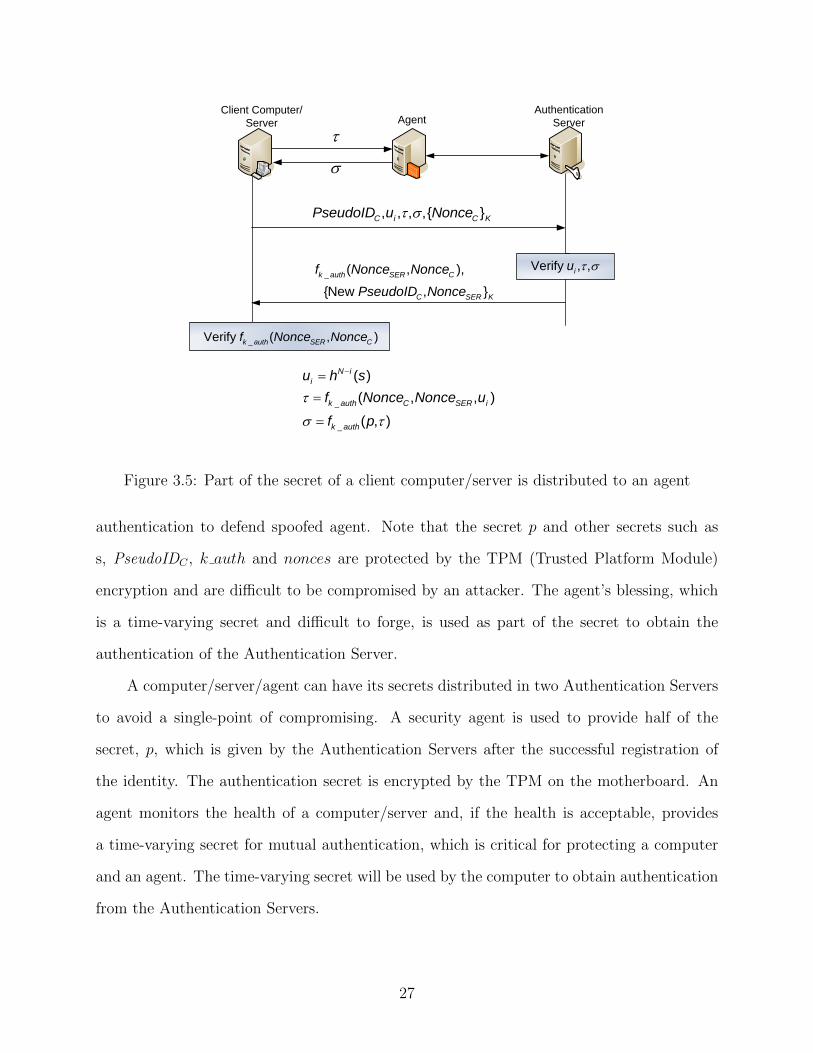
3.5 Part of the secret of a client computer/server is distributed to an agent . . . . . 27
4.1 One Authentication Server Queueing Model . . . . . . . . . . . . . . . . . . . . 34
4.2 Two Authentication Servers Queueing Model . . . . . . . . . . . . . . . . . . . 36
4.3 A 1000 node network diagram, which shows all nodes are connected to the au-thentication servers by switches using a 1 Gbps link . . . . . . . . . . . . . . . . 39
4.4 Legitimate user request RTT - under attack (100 user nodes and 900 attackernodes) . . . . . . . . . . . . . . . . . . . . . . . . . . . . . . . . . . . . . . . . . 41
4.5 Legitimate user request RTT - without attack (1000 user nodes) . . . . . . . . . 42
4.6 Server 1 CPU utillization - under attack (100 user nodes and 900 attacker nodes) 42
4.7 Server 2 CPU utilization - under attack (100 user nodes and 900 attacker nodes) 42
4.8 The average time between an attack frame leaving a node and rejected by theserver (100 user nodes and 900 attacker nodes) . . . . . . . . . . . . . . . . . . 43
4.9 Server 1 CPU utillization - under attack (200 users and 1800 attackers) . . . . . 44
4.10 Server 2 CPU utilization - under attack (200 users and 1800 attackers) . . . . . 44
viii

4.11 Legitimate user request RTT - under attack (200 users and 1800 attackers) . . . 44
4.12 Legitimate user request RTT - without attack (2000 users) . . . . . . . . . . . . 45
4.13 A network spreads over the north America continent . . . . . . . . . . . . . . . 46
4.14 A network diagram spreads over multiple continents . . . . . . . . . . . . . . . 46
4.15 Comparison for CPU utilization (%) in worldwide one-AS scenario . . . . . . . 49
4.16 Comparison for packet latency (ms) in worldwide one-AS scenario . . . . . . . . 49
4.17 Comparison for CPU utilization (%) in worldwide two-AS scenario . . . . . . . 50
4.18 Comparison for packet latency (ms) in worldwide two-AS scenario . . . . . . . . 50
5.1 System architecture of our space-time evolving authentication scheme . . . . . . 52
5.2 Application ID (AppID) and Parent AppID in Linux OS . . . . . . . . . . . . . 55
5.3 User Badge registration process . . . . . . . . . . . . . . . . . . . . . . . . . . . 57
5.4 Client Host registration process . . . . . . . . . . . . . . . . . . . . . . . . . . . 60
5.5 Security Agent registration process . . . . . . . . . . . . . . . . . . . . . . . . . 62
5.6 Flowchart of processing of Client request by SA . . . . . . . . . . . . . . . . . . 65
6.1 XML definition of an ACL rule . . . . . . . . . . . . . . . . . . . . . . . . . . . 70
6.2 Role and capability access control . . . . . . . . . . . . . . . . . . . . . . . . . . 70
6.3 Log format . . . . . . . . . . . . . . . . . . . . . . . . . . . . . . . . . . . . . . 72
6.4 Log protection scheme . . . . . . . . . . . . . . . . . . . . . . . . . . . . . . . . 73
6.5 Attack chain from outside attacker . . . . . . . . . . . . . . . . . . . . . . . . . 74
7.1 Two different approaches of attack . . . . . . . . . . . . . . . . . . . . . . . . . 80
7.2 Three stages of attack . . . . . . . . . . . . . . . . . . . . . . . . . . . . . . . . 80
7.3 Network topology . . . . . . . . . . . . . . . . . . . . . . . . . . . . . . . . . . . 82
7.4 Network topology . . . . . . . . . . . . . . . . . . . . . . . . . . . . . . . . . . . 83
7.5 Detection ratio of root attacker . . . . . . . . . . . . . . . . . . . . . . . . . . . 85
ix

List of Tables
4.1 Packet size of different payload . . . . . . . . . . . . . . . . . . . . . . . . . . . 38
4.2 The arrival rates of user and attacker packets . . . . . . . . . . . . . . . . . . . 47
4.3 Server CPU Utilization Comparison (%) under Weibull Network Traffic Model.The two server simulation results is indicated by (d) . . . . . . . . . . . . . . . 48
4.4 Network Delay (ms) Comparison under Weibull Network Traffic Model. Thetwo-server simulation results are indicated by (d) . . . . . . . . . . . . . . . . . 48
5.1 List of notations . . . . . . . . . . . . . . . . . . . . . . . . . . . . . . . . . . . 53
5.2 SA ID and Client ID mapping table . . . . . . . . . . . . . . . . . . . . . . . . 65
6.1 Components in the ACL . . . . . . . . . . . . . . . . . . . . . . . . . . . . . . . 69
x

Chapter 1
Introduction
In the rapidly exploring information era, everything goes electronically. Security and
privacy become the major concerns of US government, education institute and commer-
cial companies, especially the financial institutions. According to the Chronology of Data
Breaches [1], 540,613,790 records (still increasing) breached since 2005, far more than 1,935
data breaches made public at that time.
Intrusion to corporate networks and unauthorized access to sensitive information can
cause huge damage and intellectual property loss. According to recent study by McAfee [2],
data theft and breaches from cybercrime may have cost businesses as much as $1 trillion glob-
ally in lost intellectual property, and expenditures for repairing the damage. Cybercriminal
syndicates, such as the Russion Business Network (RBN), are becoming more professional
and sophisticated in their approach. The same is true for the efforts of state-sponsored
or terrorist groups. Recent reports from industry leader Verizon indicated that worldwide
current security practices aren’t making the grade. The firm’s 2011 Data Breach Study [3]
reports that 92% of breaches came from external sources - many capitalizing on user mistakes
to install malware that is able to pull critical data from servers and applications.
To counter the attacks, the existing methods of protection adopt Intrusion Detection
System (IDS)/Intrusion Prevention System (IPS), Anti-Malware, Network Access Control
(NAC)/Network Access Prevention (NAP), Firewall, or their combinations. However, the
frequency and sophistication of attacks on the Internet are rapidly increasing, which make
intrusion detection and prevention really challenging.
In this chapter, we discuss the underlying technical challenges of intrusion resilience
and network authentication. Then we explain the motivations for our work in intrusion
1

resilience and space-time evolving authentication. Last, the organization for the rest of the
dissertation is presented.
1.1 Challenges for Network Authentication Protocols
It is challenging to implement an intrusion-resilient authentication protocol as the fol-
lowing properties need to be considered [5]:
• Perfect Forward Secrecy (PFS) is the property that ensures that a session key de-
rived from a set of long-term public and private keys will not be compromised if one
of the (long-term) private keys is compromised in the future.
• The Privacy property means that the protocol must not reveal the identity of a par-
ticipant to any unauthorized party, including an active attacker who attempts to act as
the peer. Clearly, it is not possible for a protocol to protect both the initator and the
responder against an active attacker; one of the participants must always go first. In
general, it is believed that the most appropriate choice is to protect the initator, since
the initator is typically a relatively anonymous client, while the responder’s identity
may already be known. Conversely, protecting the responder’s privacy may not be
of much value (except perhaps in peer-to-peer communication): in many cases, the
responder is a server with a fixed address or characteristics.
• Memory-DDoS and Computation-DDoS: Denial of service (DoS) or distributed DoS
(DDoS) attack floods the authentication server with fake packets and causes the server
to exhaust its resources for processing fake packets. When the resources of the authen-
tication server are exhausted, a legitimate user’s authentication requests cannot be
processed. The major problem of DoS/DDoS attack is that the authentication server
(or responder) needs to validate that the request is from a legitimate user (or initiator).
However, the authentication server only has a limited CPU computation power and
2

restricted amount of memory. When attackers initiate sufficient requests, the authen-
tication server cannot respond to legitimate requests. It is necessary to minimize the
resources committed to a request before verifying that the request is from a legitimate
source.
• The Efficiency property is worth discussing. In many protocols, key setup must be
performed frequently enough that it can become a bottleneck to communication. The
key exchange protocol must minimize computation as well as total bandwidth and
round trips. Round trips can be especially an important factor when communicating
over unreliable media, such as wireless.
The capabilities of hackers keep increasing. In the traditional adversary model, attack-
ers can modify/record the communication, modify the messages transmitted, and initiate
authentication requests with the server or forge response to authentication request from a
legitimate user. With the rapid development of computer and electronics technology, attack-
ers are able to do more than those prescribed in the traditional model. Thus, we use the
term ”strong adversary model” to reflect the evolving capabilities of computer hackers. In
the strong adversary model, attackers can compromise either a user’s client computer or the
authentication server in addition to their capabilities in the traditional adversary model. If
an attacker subverts the client computer or the server, all stored secrets for authentication
are obtained by the adversary [4].
1.2 Challenges for Intrusion Resilience and Real-Time Forensics
The attacks have become more sophisticated in the last several years as the level of
attack automation has increased. Sample and fully functional attack software is readily
available on the Internet. Precompiled and ready to use programs allow novice users to
launch relatively large scale attacks with little knowledge of the underlying security exploits.
The advent of remote controlled networks of computers used to launch attacks has changed
3

the landscape and methods that a service provider must use. According to a study, 90% of
the vulnerable hosts were infected, within the first 10 minutes of release and the infection
doubling within 8.5 seconds [32].
There are always some new emerging threats. If the system or computer applications
are not carefully written, attackers can exploit the vulnerabilities that are not discovered
by the system administrator, thus cannot defend against zero-day attacks. After intrusion,
malwares or trojans can be injected into the compromised host. Moreover, the mutation of
the malware makes it even harder to detect such metamorphic and polymorphic malwares.
Master Boot Record (MBR) malware is another recently found advanced and probably the
stealthiest malware so far. It keeps the amount of system modifications to a minimum and
is very challenging to detect from within the infected system. Secure boot is the heart and
fundamental for application-level security [17].
It has become a well known problem that current intrusion detection systems (IDS)
produce large volumes of alerts, including both actual and false alarms. As the network
performance improves and more network-based applications are being introduced, the IDSs
are generating increasingly overwhelming alerts. This problem makes it extremely challeng-
ing to understand and manage the intrusion alerts, let alone respond to intrusions timely.
It is often desirable, and sometimes necessary, to understand attack strategies in security
applications such as computer forensics and intrusion responses. For example, it is easier to
predict an attacker’s next move, and decrease the damage caused by intrusions, if the attack
strategy is known during intrusion response. However, in practice, it usually requires that
human users analyze the intrusion data manually to understand the attack strategy. This
process is not only time-consuming, but also error-prone.
1.3 Motivation for Proposed Intrusion Resilient System
To build a system defending sophisticated attacks, a fully distributed intrusion resilient
system is needed. Fig. 1.1 illustrates the architecture of our proposed system, which consists
4

`
Agent
Client Computer/
Server
User
Agent Critical Resource
Server
Router Router
Encrypted Channel
Using ESP of IPSec
PseudoID to IP
Address TranslationTranslation
Network
Authentication
Server 1
Authentication
Server 2
Figure 1.1: A fully distributed intrusion resilient system
of client/server computers, distributed agents and distributed Authentication Servers. A
user/computer must register first using a PKI (Public Key Infrastructure) certificate and
establish a shared secret with the Authentication Servers. Then a user/computer can use the
shared secret for subsequent logins. Agents will control the access of a user/computer/agent
to critical information/service available in the network. To counter the challenges mentioned
above, we realize the necessary components in order to prove that the proposed system can
provide
(a) Resilience to a strong inside adversary who can compromise a computer, a critical re-
source server, an agent and even Authentication Servers. Examples include an attacker
compromises a client computer and cannot be authenticated by our system. An attacker
compromises either Authentication Server 1 or 2 and cannot pretend to be a legitimate
user. An attacker compromises both Authentication Server 1 and 2 and cannot pretend
to be a legitimate user for the next time period. The self-healing will be demonstrated
during the user’s next login.
(b) Self-healing capability when a strong inside adversary compromises Authentication Servers.
5

User/Client Security
AgentAuthentication
Server 1
Authentication
Server 2
Figure 1.2: Concept of space separation
(c) Resistance to DDoS attacks. We will implement a DDoS attack by using multiple com-
puters, which repetitively send in the first authentication request. The log in request of
a legitimate user should be guaranteed during the DDoS attack.
(d) Access control and health monitoring capabilities of security agents in Trusted Network
Connect (TNC)/Network Access Control (NAC)/Network Access Protection (NAP).
1.4 Motivation for Proposed Space-Time Authentication Scheme
Our goal is to build a robust and efficient system upon existing security technology and
strengthen their weaknesses. The space-time concept is to separate login credentials and
data in the realms of space and time in order to make system compromise exponentially
more difficult. Thus, we propose our space-time evolving authentication scheme. The log
creation and retrieval of every party involved should also be protected by the space-time
evolving scheme.
The credential shared by the user and authentication server should be distributed in
space to defend against single point failure problem (see Fig. 1.2). We cannot store the user
credentials in one place, as if an attacker compromises the server, they have everything to
access the critical resource.A sophisticated space separation concept is realized in a computer
access system that has multiple authentication security agents. Imagine the online banking
system that requires the user to authenticate with several authentication servers. The user
must authenticate with each authentication server before access is granted to the banking
6

K1 K2 K3 K4 K5 K6 K7 K8 K9
t
Figure 1.3: Concept of time evolving key
system. Each authentication server requires a unique password or other authentication
credential from the user. Thus space separation of login credentials is accomplished.
Time separation of login credentials is achieved by making the key evolving in each
time intervals (see Fig. 1.3). Only the owner of the key can derive the key for the next
time interval; the party involved can only verify the key. User and host must have different
keys, as user may login to different hosts. The key evolves in space as a packet propagating
through agents and routers. The logs are also protected by the time evolving keys, which
make our correlation and forensics part more secure.
Both space and time separation could fortify the system security. Thus, in this dis-
sertation, we will describe the combination of space and time separation to achieve greater
protection of critical network resources.
1.5 Dissertation Organization
This dissertation is divided into eight chapters. The first chapter provides the back-
ground information that is necessary to understand the rest of the work. The remaining
chapters are the main contribution of our work.
In Chapter 2, we introduce the previous research on intrusion resilience, authentication
and correlation. Although extensive work has been done to detect, mitigate and prevent the
intrusions, there still exist some weaknesses in the current defense mechanisms.
7

In Chapter 3, we describe the technical details of the proposed intrusion resilient, DDoS-
resistant authentication system (IDAS). We discuss how to distribute the secrets and au-
thentication servers, how to achieve DDoS-resistance and self-healing properties. The per-
formance evaluation of our proposed IDAS security system is presented in Chapter 4. The
simulations are carried out from small scale to large scale like coast to coast and continent
to continent.
In Chapter 5, the space-time evolving authentication scheme is investigated in detail.
The concept of space and time separation is illustrated in this chapter. We can see how
this separation strengthens the system security and protects the critical resources. After
the space-time authentication, we present the correlation engine and real-time forensics in
Chapter 6. The technique of how to correlate the logs on different parties and how to
present real-time forensics are discussed. In Chapter 7, the system performance of our
proposed space-time evolving authentication is examined. we talk about active attack chain,
simulation network model and the simulation results.
Finally, in Chapter 8, we summarize the results of this dissertation and draw conclusions.
Future research that could improve the system is also discussed in this chapter.
8

Chapter 2
Related Work
2.1 Related Work on Authentication
SSL (Secure Sockets Layer) protocol is widely used for authenticating users, services
and equipment as well as protecting the confidentiality and integrity of the communication.
IPSec (Internet Protocol Security) [7] is also widely used to form virtual private networks
for protecting communication between computers and networks. However, both protocols
suffer from intrusion and DDoS (distributed denial of service) attacks.
Furthermore, SSL and IPSec authentication services are critical to a network, because
when an Authentication Server is paralyzed by DDoS attacks, the network is no longer
usable. An authentication protocol must be computationally efficient when the requests to
a server are made as well as does not create a state until the authentication is successful.
It is well known that both SSL and IKEv1 (Internet Key Exchange version 1) of IPSec are
not stateless protocols [23]. Even IKEv2 [8], which was touted as a stateless protocol, has
the weakness of handling cookies in the multi-continental network and thus cannot defend a
DDoS attack at a critical moment. A number of trace-back algorithms [15,22] were proposed
to stop the DDoS attacks at the source; however, it cannot prevent the ”low and slow” attacks
and cannot eliminate collateral damage inherited in SSL [27], IPSec and Kerberos [9]. The
current version of Kerberos also has the problem of single point failure of centralized server.
All authentication services is controlled by the centralized KDC (Key Distribution Center).
If the attackers can compromise this authentication infrastructure, they can impersonate
any user.
An insider attack can compromise a server, concentrator, router, or firewall, and all cre-
dential information can be exposed [6, 10–14]. Although intrusion detection and prevention
9

systems (IDS/IPS) are deployed to detect those attacks, the high false alarm rate, ”low and
slow” attacks, and knowledgeable insiders are difficult issues to tackle [16,18–21].
An intrusion-resilient authentication protocol will be able to protect credential infor-
mation when an insider compromises a computer. Since this computer only owns partial
credential information, the protocol eliminates the single point of compromise [28]. Fur-
thermore, this protocol can readily detect the use of partial credential information as an
intrusion and indicate which part of the secret is exposed; consequently, the compromised
computer can be recovered [26]. A DDoS-resistant protocol must not create a state nor
perform computationally intensive operations when processing the incoming messages to the
server until it is authenticated [5].
2.2 Related Work on DoS/DDoS
Service providers are under mounting pressure to prevent, monitor and mitigate DoS/DDoS
attacks directed toward their customers and their infrastructure. The Internet is part of the
critical national infrastructure but is unique in that it has no customary borders to safegard
it from attacks.The number of Denial of Service(DoS) and Distributed Denial of Service
(DDoS) attacks on the Internet has risen sharply in the last several years. Expectation
level for service providers are also increasing as company revenues are directly tied to hav-
ing reliable connectivity to the Internet. The financial industry is especially susceptible to
DoS/DDoS attacks as millions of consumers move to electronic bill payments, purchases and
on-line banking.
DoS attacks can be classified as logical attacks and resource exhaustion flooding attacks
[30]. Logic attacks exploit security vulnerabilities to cause a server or service to crash or
significantly reduce performance. Resource exhaustion flooding attacks cause the server’s or
network’s resources to be consumed to the point where the service is no longer responding
or the response is significantly reduced [31]. Logic attacks will be evaluated based on their
effect on the network infrastructure and critical network services (DNS, BGP, RADIUS, etc).
10

A general method based initially on more secure packet forwarding among routers is
proposed [3] as a solution to prevent DDoS attacks. The routers are modified to provide
encryption, digital signatures, and authentication, enabling the tracing of a packet back
to its origin and thus stopping further traffic at the closest intelligent router point. Every
group of collaborating routers is called a ”hardened network”. The hardened routers should
be implemented at the border and access point of an Autonomous System. When arriving
at the first hardened router, the packet’s payload is encrypted together with one byte of
its IP address and the last hardened router before the host will decrypt it. Even though
this system provides more secure and private communication between the routers involved,
a tremendous amount of complexity is introduced, increasing cost, delay and bandwidth
parameters. In addition, knowledge of the last router is critical as it decrypts the initial
packet. Thus, a single point of failure and consequently a less reliable information system is
created.
In another defense method based on measuring traffic levels, a DDoS module is attached
to a given server making it a virtual server [6]. The module relies on a buffer through which
all incoming traffic enters. Traffic level is continuously monitored and when it shoots to
high levels, most incoming packets will be dropped. The module thus attempts to isolate
the server from the attack. It first aims to detect the beginning of the attack at time t
when the buffer becomes congested. Then the module, which can detect all active sources,
attempts to identify the source of the attack by using statistical properties of traffic flow
between t and t+ τ . Illegitimate traffic is recognized by its higher mean of traffic level and
can thus be effectively suppressed. However, this approach may cause some level of delay
and degradation on the service.
Hop-count filtering [4] and path identification mechanism [8] are also used to defend
against spoofed DDoS attacks. In Hop-count filtering, the system relies on the fact that
the number of hops between source and destination is indirectly indicated by the TTL
field in an IP packet. Linking the source IP with the sadistical number of hops to reach
11

the destination can be used as a reference to assess the authenticity of the claimed IP
source. Path identification mechanism is a method that acts to mitigate illegitimate traffic
by marking packets deterministically to detect IP address spoofing. It consists of two parts:
Marking and Filtering. The former consists of concatenating the MD5 hash of the next
node’s IP address with the current node’s IP address. The result is computed on each router
and placed in the IP identification field of the IP header, with newer values replacing older
ones when the field’s 16 bits are entirely used. The increasing sophistication of the attack
and changing of the reflective attack path make the attack path hard to identify, which
makes these approaches less effective.
2.3 Related Work on Intrusion Detection and Prevention
Intrusion detection is one of the major techniques for protecting information systems.
It has been an active research area for over 20 years since it was first introduced in the
1980s [34]. Generally, intrusion detection systems can be roughly classified as anomaly de-
tection and signature detection systems [33]. Anomaly detection involves building the normal
behavior profile for systems. The behaviors that deviate from the profile are considered as
intrusions. Signature detection looks for malicious activities by searching particular patterns
on the data against a predefined signature database. Recently, a new type of intrusion de-
tection has emerged. It is called specification based intrusion detection. Normally, this kind
of detection technique defines specifications for network protocols, and any activities that
violate specifications are considered as being suspicious. All intrusion detection has a lower
false positive rate, but it is intended for detecting known attacks. Anomaly-based detection
has the potential to detect novel attacks, but at the same time it suffers from a high false
positive rate. Moreover, it is very hard to define normal behavior for a system.
Intrusion detection systems can also be classified as host-based and network-based,
depending on the data source. A host-based intrusion detection system collects data such as
system calls, log files and resource usage from a local machine. A network-based intrusion
12

detection system detects intrusion by looking at the network traffic. These two types of
intrusion detection system are complementary, neither can be replaced by the other one.
Even through intrusion detection systems play an important role in protecting the net-
work, organizations are more interested in preventing intrusion from happening or escalating.
The intrusion prevention largely relies on the knowledge about the protected network and
the understanding of attack behaviors. However, studying the attack behavior is a challeng-
ing job as the adversaries tend to change their behavior in order not to be identified. And
at the same time, as new vulnerabilities are continually being discovered, the attacks may
use new attack strategies.
2.4 Related Work on Forensics Correlation
Forensics correlation is related to two distinct activities: intrusion detection and network
forensics. It is more important than ever that these two disciplines work together in a
mutualistic relationship in order to avoid points of failure [35]. Alert correlation is defined as a
process that contains multiple components with the purpose of analyzing alerts and providing
high-level insight on the security state of the network under surveillance. One important
use of alert correlation is to recognize the strategies or plans of different intrusions and infer
the goals of attacks. Suppose that the next step or the ultimate goal of an attack can be
identified by looking at the pattern of the intrusive behavior. We can take action to prevent
the attack from escalating and therefore minimize the damage to the asset. Alert correlation
provides a means to group different logically-connected alerts into attack scenarios, which
allows the network administrator to analyze the attack strategies.
In the past few years, a number of correlation techniques have been proposed. Generally,
they can be classified into the following categories:
• Correlation Based on Feature Similarity: These class of alert correlation ap-
proaches correlates alert based on the similarities of some selected features, such as
source IP address, target IP address, and port number. Alerts with higher degree of
13
overall feature similarity will be correlated. One of the common weakness of these
approaches is that they cannot fully discover the causal relationships between related
alerts [36].
• Correlation Based on Known Scenario: This class of methods correlate alerts based
on the known attack scenarios. An attack scenario is either specified by an attack lan-
guage such as STATL [37] or LAMDBA [38], or learned from training datasets using
data mining approach [39]. The idea of using data mining to support alarm investiga-
tion mines association rules over alarm bursts. Subsequently, alarms that are consis-
tent with these association rules are deemed ”normal” and get discarded. Some other
techniques either use episode mining to guide the construction of custom-made filtering
rules, or uses data mining techniques to learn correlation rules from hand-labeled train-
ing examples. Such approaches can uncover the causal relationship of alerts, however,
they are all restricted to known situations.
• Correlation Based on Prerequisite and Consequence Relationship: This class
of approaches is based on the observation that most alerts are not isolated, but related
to different stages of attacks, with the early stages preparing for the later ones. Based
on this observation, several studies [41,43,45] propose to correlate alerts using prereq-
uisites and consequences of corresponding attacks. Such approaches require specific
knowledge about the attacks in order to identify their prerequisites and consequences.
Alerts are considered to be correlated by matching the consequences of some previous
alerts and the prerequisites of later ones. In addition to the correlation method pro-
posed by Ning et al., JIGSAW [41] and the MIRADOR [43] are two other approaches
that use the similar paradigm. These approaches target recognition of multistage at-
tacks and have the potential of discovering unknown attacks patterns. However, such
approaches have one major limitation, that is they cannot correlate unknown attacks
(not attack patterns) since its prerequisites and consequences are not defined. Even
14

for known attacks, it is difficult to define all prerequisites and all of their possible
consequences.
• Correlation Based on Neural Network: This class of approaches are based on a
neural network [33]. Some features are extracted and trained for the neural network.
The distinguishing feature of this approach is that it uses a supervised learning method
to gain knowledge from the training examples. Once trained, the correlation engine
can determine the probability that two alerts should be correlated. Assigning corre-
lation probability can help in constructing hyper-alert graphs and attack graphs that
represent the real attack scenario. Alert graph matrix can encode correlation knowl-
edge such as correlation strength and average time interval between two types of alerts.
This knowledge is gained during the training process and is used by correlation engine
to correlate future alerts. However, these approaches have no assurance of accuracy
and exhibit extremely slow forensics.
2.5 Summary
The objective of this dissertation is to present solutions to protect critical information
against theft, defend corporate network against DoS/DDoS attacks and improve security
and efficiency in the forensics correlation process. This chapter overviewed a variety of
existing approaches related to intrusion detection and prevention, authentication, and foren-
sics correlation. Although these approaches may be effective in some circumstances, there
are some drawbacks and limitations. For intrusion detection and prevention, the signature
based approaches suffer from zero-day attack (an attack that never happened before), and
the behavior based methods have the problem of false alarm. For the current authentica-
tion protocols, they have either single point of failure, too many authentication round trips,
and many other problems. While current approaches of correlation and forensics have no
assurance of accuracy and are time-consuming. In this dissertation, two security systems,
15

which are built upon existing technology, are introduced to provide intrusion resilience and
real-time forensics.
16

Chapter 3
Intrusion-Resilient DDoS-Resistant Authentication System
In this chapter, an intrusion resilient, DDoS-resistant authentication system (IDAS) is
introduced and explained in detail. Fig. 3.1 illustrates the architecture of the proposed
IDAS security system, which consists of client/server computers, distributed agents and
distributed Authentication Servers. A user/computer must register first using a PKI (Public
Key Infrastructure) certificate and establish a shared secret with the Authentication Servers.
Then a user/computer can use the shared secret for subsequent logins. Agents will control the
access of a user/computer/agent to critical information/service available in the network. We
realize the necessary components in order to prove that the IDAS can provide (1) resilience to
a strong inside adversary who can compromise a computer, a critical resource server, an agent
and even Authentication Servers; (2) self-healing capability when a strong inside adversary
compromises Authentication Servers; (3) resistance to DDoS attacks; (4) access control and
health monitoring capabilities of security agents in TNC (Trusted Network Control)/NAC
(Network Access Control)/NAP (Network Access Protection).
3.1 Initial Registration
A new user or a new computer can be authenticated by using a PKI certificate only
once during the first handshake protocol, which is called the registration protocol (as shown
in Fig. 3.3). A secure tunnel is established for exchanging a shared seret that will be used
for subsequent authentications. A JFK-like protocol [5] needs to be used only once for a
new user/computer/agent in the registration process. After the first time registration, a
shared secret can be carried by a user either using a token generator or a smart card. A
17

Agent
Authentication
Server 1
Authentication
Server 2
Client Computer/
Server
`
User
Network
Critical Resource
Server
Figure 3.1: Overview of an intrusion-resilient, DDoS-resistant authentication system
`
User Authentication
Server
, , , ,{ }U i U KPseudoID u Nonce
_ ( , ),
{New , }
k auth SER U
U SER K
f Nonce Nonce
PseudoID Nonce
_Verify ( , )k auth SER Uf Nonce Nonce
Verify , ,iu
_
_
( )
( , , )
( , )
N i
i
k auth U SER i
k auth
u h s
f Nonce Nonce u
f p
Figure 3.2: The user secret is distributed into two factors
18
computer/agnet will have the shared secret stored in itself and associated agent. The au-
thentication of the subsequent login will be basd on the shared secret and the Authentication
Servers only need hash operations for verifying the secret without creating any state. The
identity if a user/computer/agent is changed after every successful login and every time pe-
riod. The temporary identity is call a PseudoID. Distributed agents handle the updates of
PseudoID.
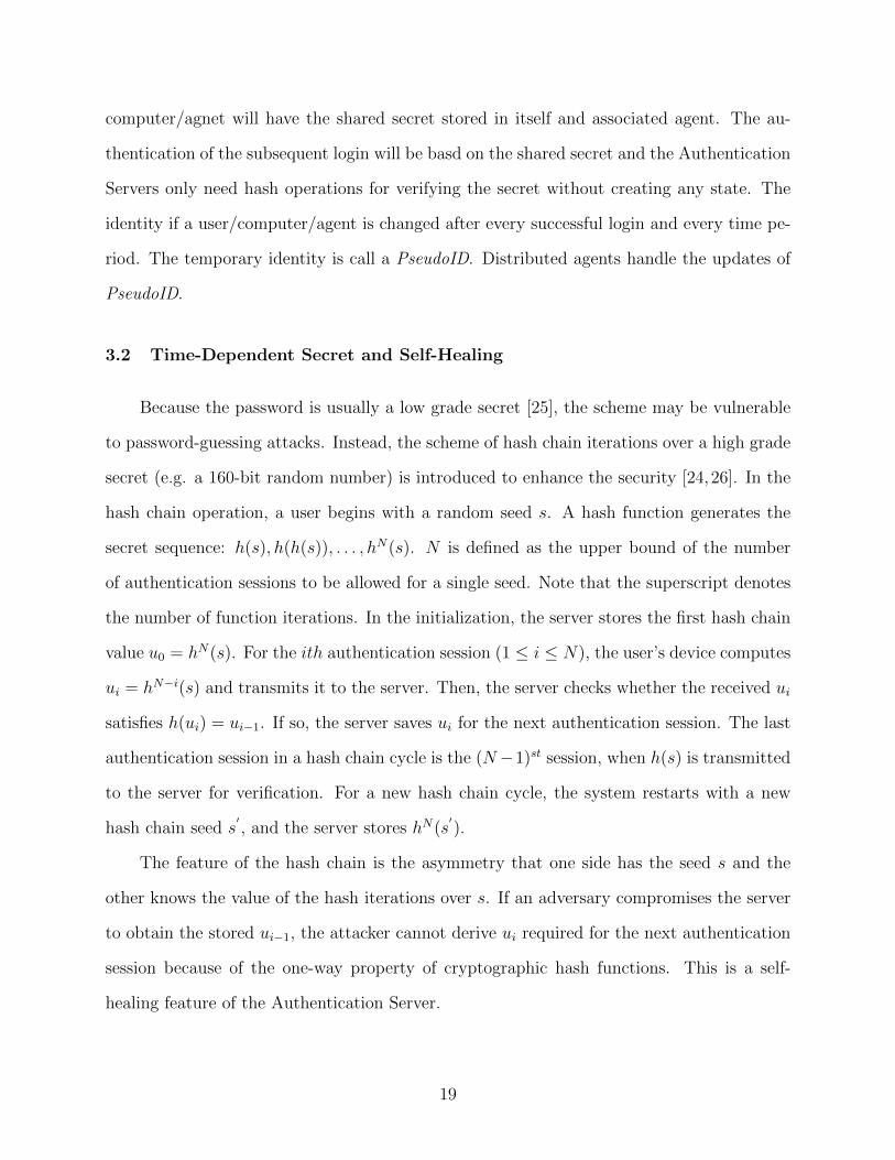
3.2 Time-Dependent Secret and Self-Healing
Because the password is usually a low grade secret [25], the scheme may be vulnerable
to password-guessing attacks. Instead, the scheme of hash chain iterations over a high grade
secret (e.g. a 160-bit random number) is introduced to enhance the security [24, 26]. In the
hash chain operation, a user begins with a random seed s. A hash function generates the
secret sequence: h(s), h(h(s)), . . . , hN(s). N is defined as the upper bound of the number
of authentication sessions to be allowed for a single seed. Note that the superscript denotes
the number of function iterations. In the initialization, the server stores the first hash chain
value u0 = hN(s). For the ith authentication session (1 ≤ i ≤ N), the user’s device computes
ui = hN−i(s) and transmits it to the server. Then, the server checks whether the received ui
satisfies h(ui) = ui−1. If so, the server saves ui for the next authentication session. The last
authentication session in a hash chain cycle is the (N−1)st session, when h(s) is transmitted
to the server for verification. For a new hash chain cycle, the system restarts with a new
hash chain seed s′, and the server stores hN(s
′).
The feature of the hash chain is the asymmetry that one side has the seed s and the
other knows the value of the hash iterations over s. If an adversary compromises the server
to obtain the stored ui−1, the attacker cannot derive ui required for the next authentication
session because of the one-way property of cryptographic hash functions. This is a self-
healing feature of the Authentication Server.
19

Run the registration protocol using
RSA-based PKI certificate
authentication for a new user/computer
Establish shared secret
&
Log in using
& shared secret
Receive
Session 1 with another computer
encrypted by derived symmetric key
Log in using &
shared secret
Receive
Session 2 with another computer
encrypted by derived symmetric key
.
.
.
1PseudoID
1PseudoID
2PseudoID
2PseudoID
3PseudoID
Figure 3.3: The authentication process includes two parts: registration process and symmet-ric key authentication
20

Notice that the iteration upper bound N must be optimal so that the re-generation
of seed and delivery of hN(s′) will not occur often. If N is too large, the client computer
will have to perform a large number of hash operations for the authentication attempts.
We propose the method of automatic update of hash chain seed, where hash operations are
applied to a random number seed to generate a sequence of random numbers as the hash
chain seeds. And the client computer will let the server know the new hash chain value
hN(s).
HMAC (RFC 2104 [29]) is the standard approach in cryptography to ensure the message
integrity. In the context of our authentication protocol, HMAC can be viewed as a fixed-size
output produced by two inputs (a message and a secret key). It is computationally infeasible
to produce the valid code without the knowledge of the key.
3.3 Distribute Two-Factor User Secrets
A legitimate user shares a p, a hash chain value and a cryptographic key k auth with
the Authentication Server. The p represents a second factor for authentication and can be
a password, a token, a biometrics or smart card. Partial secrets of the user are provided
with two random number seeds: one is for the nonce generation, and the other for the hash
chain seed. In the initial registration protocol, the device generates the first hash chain seed
s, and delivers hN(s) to the server. Fig. 3.2 describes the essential cryptographic core for
distributing a user secret into two parts.
Step 1: The user sends its identifier PseudoIDu (a time-varying ID), ui = hN−i(s) for
the ith authentication session, τ = fk auth(NonceU , NonceSER, ui), σ = fk auth(p, τ), and the
nonce NonceU (encrypted by a shared key K) to the Authentication Server. Notice that
the p is never sent out onto the communication channel. After a new user registers in an
Authentication Server, a shared secret, including PseudoIDU , NonceSER, kauth, K and p, is
given to the user and the computer in use; the user generates NonceU and s, and computes
21

u0; and NonceU and u0 are delivered to the Server. A secure channel established by the
registration protocol is used to exchange the shared secret.
Step 2: Then the server uses PseudoIDu to choose the private credentials of the user,
authentication key k auth and the p. The server then performs verification on the hash chain
value hN−i(s), the first HMAC τ , and the second HMAC σ. If any of them fails, the hand-
shake session will be dropped immediately; otherwise, the server decrypts NonceU , generates
an encrypted nonceNonceSER, a new PseudoIDu and the HMAC fk auth(NonceSER, NonceU),
and then sends them to the device. This step resists both memory-DDoS and computation-
DDoS since the HMAC computation is fast and no state is created before the verification of
HMACs is successful.
Step 3: Because the device shares k auth and knows the two nonces, it is able to
verify the received HMAC. If the HMAC is valid, the device mutually authenticates the
Authentication Server. A new PseudoIDu is received and available for next user login.
Otherwise, the device terminates the authentication immediately.
Notice that the traditional use of hash chain technique suffers from the synchronization
problem, as it becomes vulnerable to an active adversary who intercepts and traps as-yet
unused hash chain value ( [25], pp.397). However, in our scheme, the hash chain has the
HMAC protection. Without the HMAC key, replaying hash chain value will not let adver-
saries log onto the server. In practice, the user’s computer, after Step 3, will immediately
send a synchronization acknowledgement to the server. So, both sides will have the consis-
tent knowledge about the iteration number of hash chain. In the case of adversary blocking
the synchronization, the server updates the iteration number while storing the last successful
one for authenticating a legitimate user.
In each hash chain cycle, (N − 1) authentication sessions are allowed. Here, we present
the scheme of updating the hash chain value at the (N − 1)st or the last authentication
session of a hash chain cycle. Let the hash chain seed of current cycle be sj and the one for
22

the next cycle be sj+1. The new hash chain value hN(sj+1) piggybacks on Step 1,
hN−(N−1)(sj), hN(sj+1), τ
′, fk auth(p, τ
′) (3.1)
where τ′
= fk auth(NonceU , NonceSER, hN−(N−1)(sj), h
N(sj+1)). The authentication key
k auth is crucial for the authenticity of the update hN(sj+1). Upon checking the first HMAC
τ′, the server is able to discern whether the new hash chain value hN(sj+1) is intact and from
the legitimate user. Then the server stores hN(sj+1) for the next N−1 authentication sessions
of a new hash chain cycle. We give the expression for the hash chain in Step 1,
ui =
hN−i(s0) i = 1, · · · , N − 1
h2N−1−i(s1) i = N, · · · , 2(N − 1)
h3N−2−i(s2) i = 2(N − 1) + 1, · · · , 3(N − 1)
· · · · · ·
(3.2)
where i denotes the index of authentication session and the superscripts of h() denote the
number of function iterations. Each hash chain cycle (distinguished by the subscript of s)
consists of N−1 to 1. In summary, the device stores s0 and the server receives hN(s0) before
any authentication attempt. At the jth authentication session (j is multiple of (N −1)), the
piggyback operation is performed.
If an adversary compromises the device, the attacker does not know the p. If the attack
initiates the authentication request to the server, the first HMAC τ in Step 1 will be correct
since the code only requires the secrets stored in the device. Nevertheless, the second HMAC
σ will fail because the correct code requires the p. The possible choice for the attack is to
perform an online guessing attack. Note that an attacker without compromising the device
cannot get the first HMAC τ correct because of the enormous search space of HMAC key
k auth. In this case both HMACs will be wrong. As a result, when the server detects that
the first HMAC is correct and the second one is wrong, the server can infer that the device
23

has been compromised - in practice the server will set up a threshold for the number of error
occurrence as users may occasionally input wrong p. Since the correctness of one HMAC
and the invalidity of the other HMAC correspond to the case of adversary compromising the
device, we name the technique mutual HMAC.
If an adversary compromises the server, the attacker can learn the p and k auth. Since
the hash chain uses one-way function iteration over cryptographic random numbers, it is
computationally infeasible for attackers to derive the hash chain value for the next authen-
tication session. Consequently, the attacker cannot succeed in next authentication attempt.
Notice that the strong adversaries may launch the phishing attack-set up a fake server and
entice the users to log onto the bogus server. Our use of hash chain can mitigate the attack,
as the adversaries have to connect with the users first and then use the hash chain value.
Suppose the attackers phish to obtain the hash chain value for ith authentication session.
Then, for the (i + 1)th authentication session, the attacker has to undergo the handshake
with the user again. In this self-healing manner, the chance of exposing fake servers will be
significantly increased.
The proposed mutual HMAC scheme combines the usage of a p, a key, and a hash
chain in a computation-efficient manner to achieve a strong security level. If p is not used
in the protocol, when an adversary compromises the device, the attacker can succeed in
impersonating the user. If the HMAC key is not used in the protocol, the update of hash
chain value might be tampered by the adversary. Thus, the server and the device will be
out of synchronization for authentication. If the hash chain is not used in the protocol, the
adversary compromising the server learns the secret HMAC key and p. Then the adversary
can succeed in impersonating a user in the next authentication session.
3.4 Distribute Authentication Server into Two Servers
Fig. 3.4 illustrates the method of distributing the credential information of a user into
two Authentication Servers and eliminates the single-point of compromising. Server 2 is
24

User
Authentication
Server 1
11 1, , , ,{ }U i U KPseudoID u Nonce
1
_ 1 2 2
1
( , ), , ,
{New , }
k auth SER U
U SER K
f Nonce Nonce
PseudoID Nonce
1 _ 1
1 _ 1
( )
( , , )
( , )
N i
i
k auth U SER i
k auth
u h s
f Nonce Nonce u
f p
Authentication
Server 2
21 1 1, , , ,{ }U i SER KPseudoID v Nonce
22 2 2, ,{New , }U SER KPseudoID Nonce
_ 1 2Verify ( , ) andk auth SER Uf Nonce Nonce
2 _ 1 2
2 _ 2
( )
( , , )
( , )
N i
i
k auth SER SER i
k auth
v h t
f Nonce Nonce v
f p
`
1Verify , iv
Verify iu
2Verify
Figure 3.4: Distribute authentication server secret into two servers
25

hidden from a user and only Server 1 can access Server 2. This arrangement makes it
difficult to attack Server 2 directly and provides intrusion-resilient and self-healing features.
Step 1: Server 1 and Server 2 establish a secret hash chain using vi = hN−i(t) through
an initial registration protocol.
Step 2: User sends in PseudoIDU , ui, τ1, σ1, {NonceU}K1 to Server 1, and Server 1
verifies ui. Then Server 1 sends PseudoIDU , τ1, σ1, vi, {NonceSER1}K2 to Server 2.
Step 3: Server 2 verifies σ1 = fk auth(p, τ1) and vi to ensure that the user has a correct p
and Server 1 has a correct vi. If both are correct, then Server 2 sends back New PseudoIDu,
τ2, σ2, {NonceSER2}K2 to Server 1.
Step 4: Server 1 verifies τ2 = fk auth(NonceSER1, NonceSER2, vi) to make sure that
Server 2 knows k auth and sends back
fk auth(NonceSER1, NonceU), τ2, σ,{NonceSER1,NewPseudoIDU}K1 (3.3)
Step 5: User verifies fk auth(NonceSER1, NonceU) and σ2 to make sure that Server 1
and Server 2 are legitimate.
The above steps remove the single-point compromising vulnerability of critical user
authentication information. It is useless for an attacker to compromise one of the two
servers. If a strong inside attacker compromises both servers, one can pretend to be a user
for the current period. For the next time period, the attacker loses the required hash chain
value and the authentication system self heals.
3.5 Distribute Authentication Service for a Computer/Server/Agent
A client computer/server has its secret p distributed to a security agent during the
registration process. The secrecy of p is provided by the Authentication Server and stored
in an agent after a new computer/server is registered. The agent verifies the health state of
the computer and demonstrates that the agent possesses the secret k auth; this is a mutual
26
, , , ,{ }C i C KPseudoID u Nonce
_ ( , ),
{New , }
k auth SER C
C SER K
f Nonce Nonce
PseudoID Nonce
Verify , ,iu
_
_
( )
( , , )
( , )
N i
i
k auth C SER i
k auth
u h s
f Nonce Nonce u
f p
_Verify ( , )k auth SER Cf Nonce Nonce
Client Computer/
Server
Authentication
ServerAgent
Figure 3.5: Part of the secret of a client computer/server is distributed to an agent
authentication to defend spoofed agent. Note that the secret p and other secrets such as
s, PseudoIDC , k auth and nonces are protected by the TPM (Trusted Platform Module)
encryption and are difficult to be compromised by an attacker. The agent’s blessing, which
is a time-varying secret and difficult to forge, is used as part of the secret to obtain the
authentication of the Authentication Server.
A computer/server/agent can have its secrets distributed in two Authentication Servers
to avoid a single-point of compromising. A security agent is used to provide half of the
secret, p, which is given by the Authentication Servers after the successful registration of
the identity. The authentication secret is encrypted by the TPM on the motherboard. An
agent monitors the health of a computer/server and, if the health is acceptable, provides
a time-varying secret for mutual authentication, which is critical for protecting a computer
and an agent. The time-varying secret will be used by the computer to obtain authentication
from the Authentication Servers.
27

A security agent is a critical code that is running in a computer. An agent’s access right
and the health of the residing computer need to be controlled/monitored. Another agent is
used to monitor the health of the current agent’s residing computer and grants the access
rights to it. Furthermore, Authentication Servers provide the necessary secret to both agents
after the registration of the agent if another agent is available for monitoring it. The first
agent that is granted trust by the Authentication Servers is the root security agent during
the initiation of IDAS system. A tree structure is used for the connection of agents. A
parent agent of a tree monitors the child agents’ health and control access activities. An
agent establishes a secure channel with its parent agent and child agents. The shared secrets
for an agent are provided by the Authentication Servers in order to establish secure tree-type
channels. A child agent follows the same procedure by using its parent agent as the agent
for monitoring health and control activities. A tree structure based on the proximity makes
the agent communication scalable to a large network.
This scheme requires that a computer/server logs in periodically independent of user’s
activity so that self healing and health monitoring can be effective to stop attacks.
3.6 Security Analysis
In the beginning of the dissertation, the desired properties of a good authentication
system were presented. Here, in this section, we will give a security analysis of our proposed
Intrusion Resilient DDoS-Resistant Authentication System (IDAS) to see if the properties
are satisfied.
3.6.1 Resilient to Strong Adversary
In the proposed IDAS security system, it can protect against not only the passive
eavesdropper, but also the strong adversaries with some secrets. Suppose the adversary has
compromised the long-term encryption key K, or the key k auth to compute HMAC τ or
σ in the ith session (Assume it does not exceed the cap N). In the next session, the hash
28

chain value changes to µi+1 = hN−(i+1)(s). Because of one-way feature of the hash function,
knowing µi cannot guarantee that the adversary can derive the next hash chain µi+1. The
authentication server can still verify if this is an intruder or legitimate user by first comparing
the hash chain value µi and h(µi+1), as for legitimate user,
h(µi+1) = h(hN−(i+1)(s))
= hN−(i+1)+1(s)
= hN−i(s)
= µi
(3.4)
If the h(µi+1) 6= µi, the request is rejected and the packet is discarded immediately. In
our scheme, the hash chain value also has the HMAC protection. Without the HMAC key,
replaying hash chain value will not let adversaries log onto the server.
Moreover, the 160-bit NonceU and NonceSER are also time varying. For the next round,
new fresh Nonce will be generated for authentication. Suppose the encryption K or HMAC
key k auth is exposed. The adversary relays the message PseudoIDU , µi, τ, σ, {NonceU}K . If
K is exposed, the adversary computes {NonceU}K , but cannot compute the HMAC τ and
σ without having the HMAC key k auth. If HMAC key k auth is compromised, the adversary
can compute HMAC τ and σ, but cannot decrypt {NonceU}K and {NewPseudoIDU , NonceSER}K
without having key K. Even if both keys are compromised, the nonces are evolving from
time to time. The adversary cannot pass the mutual authentication without compromising
both User and Authentication Server.
3.6.2 DDoS Resistance
Denial of service (DoS) or distributed DoS (DDoS) attack floods the authentication
server with fake packets and causes the server to exhaust its resources for processing fake
packets. When the resources of the authentication server are exhausted, legitimate user’s
authentication requests cannot be responded. Denial of service relies on methods that exploit
29

the weaknesses of the network and attempts to reduce the ability of a responder to service
users [47].
The major problem of DoS/DDoS attack is that the authentication server (or responder)
needs to validate that the request is from a legitimate user (or initiator). However, even the
most powerful authentication server has a limited CPU computation power and restricted
amount of memory. When attackers initiate sufficient requests, the authentication server
cannot respond to legitimate requests. It is necessary to minimize the resource committed
to a request before verifying that the request is from a legitimate source.
Following the concept of a stateless protocol “Do not create any state or do expensive
computation before you can ensure that the received frame is legitimate”, the idea of state-
less server and stateless connection is proposed to defend against DoS/DDoS. If the server
authenticates the user and verifies the user’s PseudoIDU without keeping states, the authen-
tication scheme will be stateless. Moreover, the protocol is stateless since a frame with an
incorrect hash chain value is only checked and no other computation resource is committed.
Extending the methods proposed by [28], a new user or a new computer can be au-
thenticated by using a PKI certificate only once during the first handshake protocol, which
is called the registration protocol. A secure channel is established for exchanging a shared
secret that will be used for subsequent authentications. A JFK-like (JFK refers to Just
Fast Keying) protocol [5] needs to be used only once for a new user/computer/agent as the
registration. Even though registration protocol is not completely DDoS resistant in a multi-
continent network, the threat is not eminent and can be easily prevented since the legitimate
request is only from a new/computer/agent. After the first time registration, a shared secret
can be carried by a user either using a token generator or a smart card. A computer/agent
will have the shared secret stored in itself and associated agent. The authentication of the
subsequent login will be based on the shared secret, and the Authentication Servers only
need hash operations for verifying the secret without creating any state. If the hash gen-
erates a correct value of ui−1 using the received ui, then the decryption of nonce is carried
30

out; otherwise, the received message is dropped. Therefore, this authentication process is
efficient and DDoS resistant. Furthermore, mutual authentication is necessary in order to
prevent spoof attack. This is achieved by using a shared secret key for the hashing process
during authentication.
In our system, the legitimate user has its corresponding identifier PseudoIDU (a time-
varying ID). The authentication server will not do time-consuming decryption if the PseudoIDU
in the request is incorrect. Furthermore, we have the hash chain protection. Computing
hash chain value and comparing the values are fast and efficient. Time-consuming decryp-
tion/encryption processes will be executed if and not if the PseudoIDU , µi, τ, σ are all correct.
There are no state and time-consuming jobs committed.
3.6.3 Efficiency
In many protocols, key setup must be performed frequently enough that it can become
a bottleneck to communication. The key exchange protocol must minimize computation
as well as total bandwidth required and round trips. Round trips can be especially an
important factor when communicating over unreliable media, such as wireless. Using our
protocols, only two round-trips are needed to set up a working security association. This
is a considerable saving in comparison with existing protocols, such as IKE (Internet Key
Exchange) [8].
3.7 Summary
In this chapter, an intrusion resilient, DDoS-resistant authentication system is proposed
and explained in detail. The system achieves its goals by distributing two-factor user secrets,
distributing authentication server into two servers, and distributing authentication services
for a computer/server/agent. Even for strong adversaries, who can compromise the server
and learn some secret, it is computationally infeasible for them to derive the secrets for
next authentication session. The system is efficient as there is only one round trip in the
31

authentication. No expensive computation is committed before verifying the hash chains and
HMACs. Thus, the system is also DDoS resistant. Our work is published in proceedings of
two international conferences IEEE BROADNETS’07 [50] and ACM SPRINGSIM’08 [51].
32
Chapter 4
Performance Evaluation of Proposed IDAS System
In the beginning of this chapter, a queueing model is utilized to analyze the network
traffic. The network delay and CPU utilization could be derived from the queueing model.
Then, the simulations are carried out for small scale, as well as for long distance (coast
to coast and continent to continent). The simulations results are encouraging even in the
presence of massive attacks.
4.1 Queueing Model
In queueing theory, a queueing model is used frequently to analyze the queueing behav-
ior in real queueing situation or computer system. There are many queueing models such
as single-server queue, multiple-servers queue, open queue, and closed queue. In this dis-
sertation, we adopts the classic BCMP queueing model (it is named after Baskett, Chandy,
Muntz and Palacios [40]).
4.1.1 BCMP Queueing Network Model
To evaluate the performance of our proposed IDAS system, we need to build a queueing
model first. The packets in the buffer either originate from legitimate users or from attackers.
Hence, the total average number of packets N in the buffer is the sum of those originating
from the legitimate users and those from the attackers Na. The total number of requests
from the legitimate users Nu consists of the number of authentication packets Nauthu and the
number of data packets Ndatau .
N = Na +Nauthu +Ndata
u (4.1)
33

AS
aaS
u
dataS
u
authS
Authorized
Data Flow
Attacker
Packets
Rejected
1a
2a
aMa
1u
2u
uMu
Authenticaion
Packets
Attacker
Packets
User
Packets
1
Figure 4.1: One Authentication Server Queueing Model
For simplicity, let class r ∈ {1, 2, 3} denote the class of attacker packets, legitimate user
authentication request packets and data packets from an authenticated user, respectively.
λa and Sa are the arrival rate and service rate in the queue. We can represent the state of a
BCMP queueing network as follows:
• Let Nr represent the number of class r customers waiting in the queue.
• The overall state is given by the vector−→N = (N1, N2, N3) such that the total number
of customers in the queueing networks is given by N =∑R
r=1Nr.
4.1.2 One Authentication Server Process Model
We assume M = Ma + Mu as the total number of nodes, the ratios αu = Mu/M , and
consequently the number of attacker nodes is Ma = αa ×M = (1 − αu) ×M . At time t,
β×Mu nodes among the total legitimate user nodes Mu were authenticated and are sending
normal authenticated data packets. Assume that the queue at the authentication server is
34

first come first served (FCFS), and jobs are load-dependent, Let Vr be the visit ratio for
class r when the number of customers of class r is Nr, and µr is the service rate for class r.
The fixed population is given by the vector−→K = (K1, K2, · · · , KR) and K =
∑Ri=1Ki.
From the mean value analysis, if we define the average service demand for class r at
authentication server as Dr = Vr/µr, based on the arrival theorem [42], the expected response
time Rr and expected waiting time Wr for a class r customer are given as follows:
E[Rr] = Dr(R∑
j=1
E[Nj(−→K − 1j)] + 1) (4.2)
E[Wr] = (E[Nr(K − 1)])E[Rr] (4.3)
where 1j represents a unit-vector with a 1 one the j-th position. The overall service response
time for authentication service can be expressed as
E[R] =R∑
r=1
ηrE[Rr] (4.4)
where
η1 = αa, η2 = (1− β)αu, η3 = βαu. (4.5)
Assume the server’s processor capability is Ucap which means the CPU of the server
can process as many as Ucap instructions per CPU clock cycle. Let I denote the number of
instructions needed to complete an attacker job per unit time, and T denote time needed to
process an instruction. We can compute the server CPU utilization U as:
U =IKE[R]
TUcap=I∑3
r=1Nr∑3
r=1 ηrE[Rr]
TUcap(4.6)
From the above derivation, we can also get the delay D at the authentication server as
E[D] =3∑
r=1
ηrE[Wr] (4.7)
35

AS1
aaS
u
dataS
u
authS
Authorized
Data Flow
Attacker
Packets
Rejected
1a
2a
aMa
1u
2u
uMu
AS2
Authenticaion
Packets
Attacker
Packets
User
Packets
1
Figure 4.2: Two Authentication Servers Queueing Model
4.1.3 Two Authentication Servers Process Model
For two authentication server case, we can represent the state of BCMP queueing net-
work model as follows:
• Let−→Ni = (Ni,1, Ni,2, Ni,3) be the state of authentication servers.
• Ni,r represents the number of class r customers waiting in the queue at authentication
server i = 1, 2.
• The overall state is given by the vector−→N = (
−→N 1,−→N 2,−→N 3) and the overall number
of customers in the queueing networks is given by Ni =∑3
r=1Ni,r, R = 3. The fixed
population of jobs is given by the vector−→Ki = (Ki,1, Ki,2, · · · , Ki,R) and Ki =
∑Rr=1Ki,r.
• Let Vi,r be the visit ratios for class r at authentication server i, given number of class
r customers Ni,r, and µi,r is the service rate for class r at authentication server i.
36

From the mean value analysis, if we define the average service demand for class r at
authentication server i as Di,r = Vi,r/µi,r, based on the arrival theorem, the response time
and waiting time for a class r customer at authentication server i is given as follows:
E[Ri,r] = Di,r(R∑
j=1
E[Ni,j(−→Ki − 1j)] + 1) (4.8)
E[Wi,r] = (E[Ni,r(Ki − 1)])E[Ri,r] (4.9)
The ovrall service response time for authentication server AS1 can be expressed as
E[R1] =R∑
r=1
η1,rE[R1,r] (4.10)
where η1,r are given as
η1,1 = αa, η1,2 = (1− β)αu, η1,3 = βαu (4.11)
The overall service response time for authentication server AS2 can be expressed as
E[R2] =R∑
r=1
η2,rE[R2,r] (4.12)
where η2,r are given as η2,1 = (1− β)αu, η2,2 = βαu.
Assume the server’s processor capability is Ucap which means the CPU of the server
can process as much as Ucap instructions per CPU clock cycle. Let I denote the number of
instructions needed to complete an attacker job per unit time. We can compute the server
CPU utilization U as follows:
U1 =IK1E[R1]
TUcap=I∑3
r=1N1,r∑3
r=1 η1,rE[R1,r]
TUcap(4.13)
U2 =IK2E[R2]
TUcap=I∑2
r=1N2,r∑2
r=1 η2,rE[R2,r]
TUcap(4.14)
37

Table 4.1: Packet size of different payload
TYPE SIZE(bytes)IDAS Header 21PseudoID Payload 6Hash Chain Payload 20First HMAC Payload τ = fk auth(NonceU , NonceSER, µi) 20Second HMAC Payload σ = fk auth(p, τ) 20Nonce 20Authentication Payload 32Encrypted Payload 32Attack IP Packet 86
From the above derivation, we can also get the delay D at the authentication server
AS1
E[D] =R∑
r=1
η1,rE[W1,r] (4.15)
4.2 Performance Evaluation
4.2.1 Network Simulation Parameters
We run the simulation in OPNET Modeler 14.0.A PL2 version on a PC with Pentium 4,
2.20GHz CPU, 2GB RAM and running the Microsoft Windows XP operating system. Table
4.1 shows the packet size for different payload. We have a detailed documentation of IDAS
packet format.
4.2.2 Simulation on Network within Short Distance
Simulation scenarios
By using OPNET Rapid Configuration in the Topology menu bar, we could set up a
star topology rapidly. For a 1000 node case, a network diagram is shown in Fig. 4.3. After
that, we could do the following steps to complete the simulation scenario setup:
38

Figure 4.3: A 1000 node network diagram, which shows all nodes are connected to theauthentication servers by switches using a 1 Gbps link
39

1) First of all, we should create the nodes to denote the user nodes, attacker nodes and
servers.
a) The server is Dell PowerEdge 1855, 1 CPU, 1 Core per CPU, 3.6GHz, 4GB RAM.
b) Each node is a Dell Dimension 2400, 1 P4 CPU - 2.20 GHz, 512 MB RAM, and Buffer
size is 512 KB.
c) The switch is 3Com 3C SSII 1100 3300 4s ae52 e48 ge3 with 4 MB buffer/port and
has the switch packet service rate of 1.2 M packets/sec.
d) The NIC (Network Interface Controller) buffer size is 64 K bytes and OS buffer size
is 4 M bytes.
2) Then, we set up the link between the nodes using a 1Gbps link.
3) After that, we should set up the traffic over the link by exponential inter-arrival process
for the attacker and user nodes.
4) We use the built-in server model in Opnet for simulating authentication servers for pro-
cessing the packets sent from attackers and users.
The user and attacker nodes are in the periphery of the star topology network, connect-
ing to the central switch. Then the switch is connected to the authentication server 1 by a
link of 1Gbps, and the server 1 connects to server 2 also via a 1Gbps link.
From our packet size of different payload definition in Table 4.1, the packet size from user
to authentication server 1 is 107 bytes. The nodes will send the packet to authentication
server 1 following the exponential distribution. In the scenario, we use random number
generator to simulate the attackers and the legitimate users. Generate a random number
x, using uniform distribution, U [0 ∼ 1]. If x > 0.1, the node is assigned to simulate an
attacker, else the node is assigned to simulate a legitimate user. So if there is a total 1000
nodes, there will be 100 legitimate user nodes and 900 attacker nodes.
40

Figure 4.4: Legitimate user request RTT - under attack (100 user nodes and 900 attackernodes)
Case 1 performance: 100 user nodes and 900 attacker nodes
The following results are based on the 1000 nodes, which has 10% legitimate user nodes
and 90% attacker nodes. The total number of legitimate user nodes is 100, and the number
of attacker nodes is 900. The initial random seed for the simulation is 128 (this is used for
reproducing the simulation).
The exponential inter-arrival time for a user node is 0.001 sec. In a real world, a
user sends an authentication request with a rate far less than 1 per minute. The 0.001 sec
exponential inter-arrival time for a user node is actually equivalent to more than 10,000 users’
traffic for authentication requests. 100 user nodes actually represent more than 1,000,000
users; thus, the load of authentication requests imposed on the authentication servers is
beyond today’s network load. The exponential inter-arrival time for an attacker node is
0.001 sec; thus the generated traffic fully utilizes the link from switch to Server 1 (close to
100%).
The simulation starts at 105 seconds, and the system is idle between time 0 to 105s.
From Fig. 4.4, 4.5, 4.6, and 4.7, IDAS system performance is compared in the scenarios
with attackers and without attackers. As shown in Fig. 4.8, the average time between an
attack frame leaving a node and rejected by the server is short. During the appearance of
41
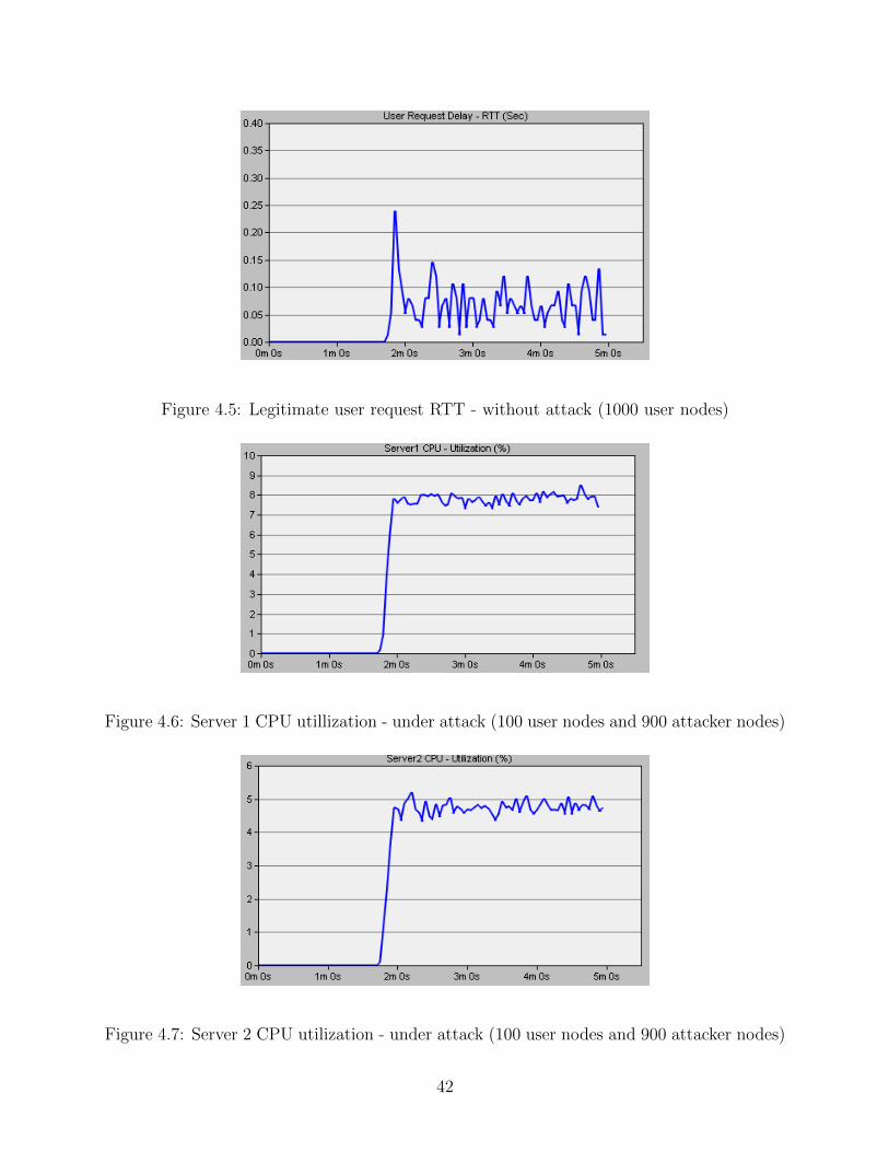
Figure 4.5: Legitimate user request RTT - without attack (1000 user nodes)
Figure 4.6: Server 1 CPU utillization - under attack (100 user nodes and 900 attacker nodes)
Figure 4.7: Server 2 CPU utilization - under attack (100 user nodes and 900 attacker nodes)
42

Figure 4.8: The average time between an attack frame leaving a node and rejected by theserver (100 user nodes and 900 attacker nodes)
large volume attackers, the legitimate users cannot really sense the attack activities during
authentication, as indicated by the slight increase of delay in Fig. 4.4 and 4.5. To illustrate
the capability of servers under attack, as shown in Fig. 4.6 and 4.7, both servers have low
utilization rate (peak at 8.5%) during the attack. They should be able to handle even more
punishment.
Case 2 performance: 200 user nodes and 1800 attacker nodes
In comparison to Case 1, the Server 1 utilization rate is up to 13% from 8.5%. Both
servers should have capabilities to take heavier DDoS punishment form more attackers. The
peak RTT latency is increased from 0.325 ms (Case 1) to 0.35 ms (Case 2). This comparison
further confirms IDAS scalability of providing normal authentication service to users even
under heavy attacks without any collateral damage.
4.2.3 Simulation with Queueing Model for Long Distance Network
Simulation scenarios and parameters
Three scenarios were simulated:
43

Figure 4.9: Server 1 CPU utillization - under attack (200 users and 1800 attackers)
Figure 4.10: Server 2 CPU utilization - under attack (200 users and 1800 attackers)
Figure 4.11: Legitimate user request RTT - under attack (200 users and 1800 attackers)
44

Figure 4.12: Legitimate user request RTT - without attack (2000 users)
1) One Authentication Server (AS) for a network spreading from coast to coast in North
America continent as shown in Fig. 4.13.
2) One AS for a network spreading multiple continents as show in Fig. 4.14.
3) Two ASs for a network spreading multiple continents.
Following is the list of equipment that are used in the simulations:
• 15 switches: 3Com, model - 3C SSII 1100 3300 4s ae52 e48 ge3
• Authentication Server: Dell, model - Dell PowerEdge 1855 2 CPU, 1 Core Per CPU,
3600MHz, 8GB RAM, Microsoft Windows Server 2003 Standard x64 Edition System
• 200 laptops: Lenovo Thinkpad T43 Type 1871-48u: 1CPU, 1 Core(s) Per CPU,
1600MHz, 1GB RAM, WinXP System
• 800 desktops: Dell Precision Workstation 650: 1 CPU, 1 Core(s) Per CPU, 3200MHz,
1GB RAM, WinXP System
• Backbone Link and AS link: 10Gbps, model - 10Gbps Ethernet adv
• Computer’s link to switch: 1 Gbps Ethernet
45

Figure 4.13: A network spreads over the north America continent
Figure 4.14: A network diagram spreads over multiple continents
46

Table 4.2: The arrival rates of user and attacker packets
Packet arrival rate (per second) Packet size(bytes)User authentication request 0.0235 86User data after authentication 1.667× 10³ 512Attacker packet (coast to coast) 6.847× 10⁵ 86Attacker packet (worldwide) 2.263× 10⁶ 86
• Users: 100 nodes
• Attacker: 900 nodes
• Users and attackers are randomly distributed
• The attack rate and user packet rate is adjusted to fill the 10 Gbps backbone link to
the AS
All packets are generated based on the Weibull Traffic Model. As shown in Table 4.2,
legitimate user’s average authentication request rate is 0.0235 per second, such as traveling
in a mobile network. After authenticated, user’s data packet has a mean arrival rate of
1.667 × 10³. The attacker’s packet rate is adjusted to fill up the 10 Gbps pipe to the
authentication server (AS).
Simulation results and comparisons
The simulations of all traffic are launched at t= 105 second (s) as the default set by
OPNET software. As shown in Table 4.3, when under massive DDoS attacks, the AS CPU
utilization rate increases about 16%. The latency increases about 0.04 to 0.06 seconds (as
shown in Table 4.4) that cannot be sensed by a legitimate user. There is no collateral damage
to legitimate users during massive DDoS attacks.
To compare the simulation and modeling results, Fig. 4.15 and 4.16 show the CPU
utilization and packet latency in a worldwide network, when the attacks were launched at
t = 105 s against one authentication server. The comparisons between simulation result
47

Table 4.3: Server CPU Utilization Comparison (%) under Weibull Network Traffic Model.The two server simulation results is indicated by (d)
CPU utilization (%) under attack CPU utilization (%) without attackCoast to coast 30.31 26.32Worldwide 35.83 30.94Worldwide (d) 11.78/8.32 10.21/7.56
Table 4.4: Network Delay (ms) Comparison under Weibull Network Traffic Model. Thetwo-server simulation results are indicated by (d)
Network delay (ms) under attack Network delay (ms) without attackCoast to coast 303.7 257.6Worldwide 368.4 316.1Worldwide (d) 145.1 113.2
and queueing model show a difference of 7% for CPU utilization, and a difference of 5% for
packet latency, respectively. Fig. 4.17 and Fig. 4.18 illustrate the comparison results for
two authentication server in worldwide scenario. The comparisons between simulation result
and queueing model show a difference of 8% for CPU utilization, and a difference of 6% for
packet latency respectively. We can see the agreement between simulation and modeling
results is adequate.
4.3 Summary
In this chapter, the performance of proposed IDAS system is evaluated. To model
network delay and CPU utilization of authentication servers, a BCMP queueing network
is utilized to analyze the network. Later on, comprehensive simulations are carried out on
different scenarios like coast to coast and continent to continent. The simulation results prove
that the proposed system is fast and efficient to massive attacks. This work is published
in proceeding of ACM SpringSim 2008 [51] and International Journal of Information and
Computer Security [52].
48

Figure 4.15: Comparison for CPU utilization (%) in worldwide one-AS scenario
Figure 4.16: Comparison for packet latency (ms) in worldwide one-AS scenario
49

Figure 4.17: Comparison for CPU utilization (%) in worldwide two-AS scenario
Figure 4.18: Comparison for packet latency (ms) in worldwide two-AS scenario
50

Chapter 5
Space-Time Evolving Authentication Scheme
The key concept of the this proposed scheme is space-time evolving. It means that the
key evolves from time to time, and from location to location. Only the owner of the key
can derive the key for the next time interval, while the party involved can only verify the
key. User asset and host have different keys. The key also evolves in space as a packet
propagating through agents and routers. All the related activities should be logged and the
logs are protected by the space-time evolving keys.
Fig. 5.1 illustrates the architecture of our proposed space-time evolving authentication
scheme. Security agent coordinates a group of user/client, while the super security agent
coordinates a group of security agents. The incoming and outgoing requests of application
server (in our case, database server) are also checked by the front security agent. The logs
of every involved entity are stored and protected by the space-time evolving keys. To create
or retrieve the logs, appropriate keys should be presented. Otherwise, the request is rejected
and the activity is added to log.
First, we will list some notations used in our proposed space-time evolving authentica-
tion scheme.
5.1 Components
The key of proposed scheme is to protect and control access to sensitive data stored
in the central Database Server. The user with a Badge uses a Client computer to log in
to the database to access sensitive data. Both the user and the client must be registered
beforehand. Access to the database is controlled by a group of the Security Agents (SA)
and the Super Security Agent (SSA). When a User wishes to access sensitive data stored on
51

Security Agent (SA)
Database Server (DS)
Authentication Server (AS)
Super Security Agent (SSA)
`Security
Agent (SA)
User/Client
ACL
ACL
ACL
ACL
Figure 5.1: System architecture of our space-time evolving authentication scheme
52

Table 5.1: List of notations
U UserC Client HostB BadgeSA Security AgentSSA Super Security AgentAS Authentication ServerDS Database Serverhk(M) Keyed hash operation of message M using key k.{M}k Encryption using symmetric key kh2k(M) Double keyed hash operation of message M .IDU User identifierSU User passwordIDC Client Host identifierIDSA Security Agent identifierOPTC,AS One-time password of Client Host and Authentication ServerOPTC,SA One-time password from Client to Security AgentOPTSA,C One-time password from Security Agent to ClientSN A 32-bit sequence numberPIDU User pseudo identifierPIDC Client Host pseudo identifierPIDSA Security Agent pseudo identifierKa Authentication keyKe Encryption keyTU A timestamp generated by UserTB A timestamp generated by BadgeTSA A timestamp generated by Security AgentTSSA A timestamp generated by Super Security AgentTAS A timestamp generated by Authentication ServerµU,AS HMAC of User of Authentication ServerAU,AS Authenticator between User and Authentication ServerVU,AS Verifier between User and Authentication ServerµC,AS HMAC of Client and Authentication ServerAU,AS Authenticator between Client and Authentication ServerVU,AS Verifier between Client and Authentication ServerµSA,AS HMAC of Security Agent and Authentication ServerAU,AS Authenticator between Security Agent and Authentication ServerVU,AS Verifier between Security Agent and Authentication ServerHC,SA Authenticator of each packet.
53

the Database Server (DS), he must own a Badge (Smart Card) and a User password. These
two security tokens are used in conjunction with a secret held by the Client in order to
authenticate the User with the DS. The User/Client must authenticate with each of several
SAs individually, with the authentication process being controlled and monitored by one of
the SSAs. The authentication credentials change both per session and per packet.
The following are some components needed in the authentication process:
1) ID and PseudoID (PID)
Both the User and the Client are assigned 160-bit permanent ID numbers upon regis-
tration with the authentication system. This allows the SAs, SSAs, and AS to identify
who is attempting to login and to find the authentication information for that User and
Client. In addition, the User and the Client are also assigned temporary Pseudo IDs
(PID). These are randomly-generated IDs which are changed every login session. The
PID is used to protect the real identity of User. When a User attempts to login to the au-
thentication system, he must possess the correct permanent IDs for both User and Client
as well as the correct PIDs for both User and Client. During login, the User and Client
are identified by their PIDs, and Permanent IDs are verified later in the login process.
2) Timestamp (T)
The timestamp is needed to record the time for every request. In our implementa-
tion, we adopt the Network Time Protocol (NTP) [48]. NTP is a protocol and software
implementation for synchronizing the clocks of computer systems over packet-switched,
variable-latency data networks. The 64-bit timestamp in our system is generated using
NTPv4 T = NTPTimeReq().
3) Application ID (AppID) and Parent Application ID
54

Figure 5.2: Application ID (AppID) and Parent AppID in Linux OS
For every application the operating system is assigned an application ID. Fig. 5.2 demon-
strates the application ID and parent application ID in the Linux OS. In a chain of ap-
plications, an application also has its parent application, which the application originates
from. In our system, when a User/Client wishes to communicate with the DS or another
Client, the Client must first download a small application from an SA. This application
is used to establish subsequent communication with the DS or another Client. This ap-
plication must be downloaded for each new session. Each application that is dispensed
by the SA has a random unique AppID. The SAs maintain logs detailing which AppIDs
were issued to which Clients at which times.
When a Client sends a message, the packet contains two fields current AppID and Parent
AppID. The current AppID field contains the AppID of the application that sent the
packet. If the packet was created in response to an earlier packet received from another
Client, then the Parent AppID field contains the AppID of the original packet. Other-
wise, the Parent AppID field contains the same value as the current AppID field. For
example, if Client A sends a message to Client B instructing Client B to send a different
message to Client C, then the packet from Client A contains Client A’s AppID in both
the current AppID and Parent AppID fields. The packet sent from Client B to Client
C will contain Client B’s AppID in the current AppID field and Client A’s AppID in
the Parent AppID field. The current and Parent AppIDs will be utilized later during
correlation and traceback.
55

4) One-Time Password (OPT)
The One Time Password (OTP) is a per packet password that authenticates the User or
Client with an individual SA. The OTP is a hash of previously established keys that are
shared between the Client or the User and each individual SA, and a sequence number.
The Client or User has an authentication relationship with each SA; each relationship
consists of an independently established set of keys and sequence number (space sepa-
ration). The sequence number increments for each packet; thus, the OTP is different
for each packet (time separation). Also, the keys are changed after each login session
initiated by a Client or User (time separation). Possession of the correct keys, which are
secrets, and the correct sequence number, which is not a secret, is necessary to correctly
calculate the OTP.
5) Content ID and Authorization (Permissions)
Each piece of sensitive information on the Database is identified by a unique Content ID.
A piece of sensitive information may exist in one place, or it may be split into several
pieces with each piece having a unique Content ID and residing in different locations on
a single Database or in locations across multiple Databases (space separation). When
a User requests access to the sensitive information, he must possess all of the correct
Content IDs. It is also possible to change these Content IDs over time (time separation).
Access to sensitive information is also controlled by means of authorization privileges
(permissions). The SSAs maintain an access control list, which specifies which Clients
and which Users are permitted to access which pieces of sensitive information. The SSAs
also share this list with the SAs. Whenever an SA or an SSA handles an information
access request, the calling Client/User is checked against the access control rules for that
particular piece of information.
6) Security Ticket
When a sensitive data access request is sent from the User/Client to the Database, it must
56

UT
1. is the moment of registration, either by
face to face or by remote secure tunnel.
],[ UTIDU
AST
T T T
],[ ASTIDU
],[ ,SSAASU hID
2. AS logs , generates its own
timestamp and sends to SSA
3. SSA generates its timestamp , and
computes ),,,(2
, ASSSAUSSASSAAS TTIDShh
),,,( ,
2
,, USSAASASUUSSAAS ThSIDhh
4. AS computes and logs
AS also computes KAU, KEU
)"",,,(
)"",,,(
,,
2
,,
2
EncrUserThIDhK
AuthUserThIDhK
UUSSAASUE
UUSSAASUA
U
U
],,[ ,, USSAASUU hIDPID
BT ],,,[ , BASUUU TVIDPID
5. User types in SU, and B computes
),,,,( ,,
2
, USSAASBUUUASU hTSPIDIDh
),,( ,
2
, BUASUASU TShA
)( ,
2
, ASUASU AhV
UT UTIDU ,
AST
SSAT
SSAT
USSAASh ,,
Figure 5.3: User Badge registration process
first clear the SA barrier and the SSA barrier. The packet must clear each of a number
of SAs by passing PID, OTP, and authorization (permissions) checks. The packet also
carries a Security Ticket; when an SA authenticates and authorizes a packet, it ”stamps”
the packet’s Security Ticket before sending it to the next SA. This allows future SAs to
verify which SAs the packet has previously cleared.
5.2 Registration Process
5.2.1 User Badge Registration
User with a Badge needs to register with AS and SSA first before mutual authentication
stage. The registration process is processed either via face-to-face in the registration office,
or via a remote secure tunnel. In either case, Users need to present enough identifications
57

to prove he/she has corresponding privilege to register. Here are the detailed registration
process (see Fig. 5.3):
Step 1: User =⇒ AS
timestamp TU is the moment of registration, and IDU is the real identity of User. User
delivers [IDU , TU ] to AS for registration.
Step 2: AS =⇒ SSA
After AS received User’s request, it logs IDU , TU , generates its own timestamp TAS and
forwards the request [IDU , TAS] to SSA.
Step 3: SSA
SSA logs IDU , TSSA, TAS, and hAS,SSA. It generates its own timestamp TSSA, and computes
hAS,SSA = h2(SSSA, IDU , TSSA, TAS) (5.1)
where SSSA is the secret of SSA.
Step 4: AS ⇐= SSA
In this step, AS first computes and logs
hAS,SSA,U = h2(IDU , SAS, hAS,SSA, TU) (5.2)
where hAS,SSA is received from SSA, and SAS is the secret of AS. Then it computes authen-
tication key KaU and encryption key Ke
U respectively.
KaU = h2(IDU , hAS,SSA,U , TU , “User AUTH”) (5.3)
KeU = h2(IDU , hAS,SSA,U , TU , “User ENCR”) (5.4)
After that, AS sends [PIDU , IDU , hAS,SSA,U ] to the User.
Step 5: User ⇐= AS
58

After User received response from AS, it types in SU . The Badge B computes
µU,AS = h2(IDU , P IDU , SU , TB, hAS,SSA,U) (5.5)
where SU is the User secret, TB is the current timestamp, and hAS,SSA,U is received from AS.
It also computes
AU,AS = h2(µU,AS, SU , TB) (5.6)
VU,AS = h2(AU,AS) (5.7)
When User knows µU,AS, AU,AS, and VU,AS, it sends [PIDU , IDU , VU,AS, TB] to the AS. AS
will log the activity and stores the credentials from authentication process.
After the registration, AS has verifier VU,AS and shares authentication key KaU and encryption
key KeU with the user. User can generate OPTU,AS with the keys.
5.2.2 Client Host Registration
Fig. 5.4 shows the registration of Client. The registration process is similar to User
registration.
Step 1: Client =⇒ AS
timestamp TC is the moment of registration, and IDC is the real identity of Client. Client
delivers [IDC , TC ] to AS for registration.
Step 2: AS =⇒ SSA
After AS received Client’s request, it logs IDC , TC , generates its own timestamp TAS and
forwards the request [IDC , TAS] to SSA.
Step 3: SSA
SSA logs IDC , TSSA, TAS, and hAS,SSA. It generates its own timestamp TSSA, and computes
hAS,SSA = h2(SSSA, IDC , TSSA, TAS) (5.8)
59

CT
1. is the moment of registration, either by
face to face or by remote secure tunnel.
],[ CC TID
AST
T T T
],[ ASTIDC
],[ ,SSAASC hID
2. AS logs , generates its own
timestamp and sends to SSA
3. SSA generates its timestamp , and
computes ),,,(2
, ASSSACSSASSAAS TTIDShh
),,,( ,
2
,, CSSAASASCCSSAAS ThSIDhh
4. AS computes and logs
AS also computes
)"",,,(
)"",,,(
,,
2
,,
2
EncrUserThIDhK
AuthUserThIDhK
CCSSAASCE
CCSSAASCA
C
C
],,[ ,, CSSAASCC hIDPID
CT ],,,[ , CASCCC TVIDPID
5. Client C computes
),,,,( ,,
2
, CSSAASCCCCASC hTSPIDIDh
),,( ,
2
, CCASCASC TShA
CT CC TID ,
AST
SSAT
SSAT
CSSAASh ,,
CAKCEK
)( ,
2
, ASCASC AhV
Figure 5.4: Client Host registration process
60

where SSSA is the secret of SSA.
Step 4: AS ⇐= SSA
In this step, AS first computes and logs
hAS,SSA,C = h2(IDC , SAS, hAS,SSA, TC) (5.9)
where hAS,SSA is received from SSA, and SAS is the secret of AS. Then it computes authen-
tication key KaC and encryption key Ke
C respectively.
KaC = h2(IDC , hAS,SSA,C , TC , “Client AUTH”) (5.10)
KeC = h2(IDC , hAS,SSA,C , TC , “Client ENCR”) (5.11)
After that, AS sends [PIDC , IDC , hAS,SSA,C ] to the Client.
Step 5: Client ⇐= AS
After Client received response from AS, it computes
µC,AS = h2(IDC , P IDC , SC , TC , hAS,SSA,C) (5.12)
where SC is the Client’s secret, TC is the current timestamp, and hAS,SSA,C is received from
AS. It also computes
AC,AS = h2(µC,AS, SC , TC) (5.13)
VC,AS = h2(AC,AS) (5.14)
When Client knows µC,AS, AC,AS, and VC,AS, it sends [PIDC , IDC , VC,AS, TC ] to the AS. AS
will log the activity and stores the credentials from authentication process.
After the registration, AS has verifier VC,AS and shares authentication key KaC and encryption
key KeC with the Client. Client can generate OPTC,AS with the keys.
61

SAT
1. is the moment of registration, either by
face to face or by remote secure tunnel.
],[ SASA TID
AST
T T T
],[ ASSA TID
],[ ,SSAASSA hID
2. AS logs , generates its own
timestamp and sends to SSA
3. SSA generates its timestamp , and
computes ),,,(2
, ASSSASASSASSAAS TTIDShh
),,,( ,
2
,, SASSAASASSASASSAAS ThSIDhh
4. AS computes and logs
AS also computes
)"",,,(
)"",,,(
,,
2
,,
2
EncrSAThIDhK
AuthSAThIDhK
SASASSAASSA
e
SA
SASASSAASSA
a
SA
],,[ ,, SASSAASSASA hIDPID
SAT ],,,[ , SAASSASASA TVIDPID
5. Security Agent SA computes
),,,( ,,
2
, SASSAASSASASAASSA hTSIDh
),,( ,
2
, SASAASSAASSA TShA
)( ,
2
, ASSAASSA AhV
SAT SASA TID ,
AST
SSAT
SSAT
SASSAASh ,,
SAAKSAEK
Figure 5.5: Security Agent registration process
5.2.3 Security Agent Registration
Fig. 5.5 shows the registration of Security Agent. The registration process is also similar
to User registration and Client registration.
Step 1: SA =⇒ AS
timestamp TSA is the moment of registration, and IDSA is the real identity of Security Agent.
Security Agent delivers [IDSA, TSA] to AS for registration.
Step 2: AS =⇒ SSA
After AS received Security Agent’s request, it logs IDSA, TSA, generates its own timestamp
TAS and forwards the request [IDSA, TAS] to SSA.
Step 3: SSA
62

SSA logs IDSA, TSSA, TAS, and hAS,SSA. It generates its own timestamp TSSA, and computes
hAS,SSA = h2(SSSA, IDSA, TSSA, TAS) (5.15)
where SSSA is the secret of SSA.
Step 4: AS ⇐= SSA
In this step, AS first computes and logs
hAS,SSA,SA = h2(IDSA, SAS, hAS,SSA, TSA) (5.16)
where hAS,SSA is received from SSA, and SAS is the secret of AS. Then it computes authen-
tication key KaSA and encryption key Ke
SA respectively.
KaSA = h2(IDSA, hAS,SSA,SA, TSA, “SA AUTH”) (5.17)
KeSA = h2(IDSA, hAS,SSA,SA, TSA, “SA ENCR”) (5.18)
After that, AS sends [PIDSA, IDSA, hAS,SSA,SA] to the Client.
Step 5: SA ⇐= AS
After SA received response from AS, it computes
µSA,AS = h2(IDSA, P IDSA, SSA, TSA, hAS,SSA,SA) (5.19)
where SSA is the SA’s secret, TSA is the current timestamp, and hAS,SSA,SA is received from
AS. It also computes
ASA,AS = h2(µSA,AS, SSA, TSA) (5.20)
VSA,AS = h2(ASA,AS) (5.21)
63

When SA knows µSA,AS, ASA,AS, and VSA,AS, it sends [PIDSA, IDSA, VSA,AS, TSA] to the AS.
AS will log the activity and stores the credentials from authentication process.
After the registration, AS has verifier VSA,AS and shares authentication key KaSA and en-
cryption key KeSA with the SA. SA can generate OPTSA,AS with the keys.
5.3 Authentication Process
5.3.1 Client Host Authentication
Mutual authentication between Client and AS occurs after registration process, during
which AS has verifier VC,AS and shares authentication key KaSA and encryption key Ke
SA with
the Client. We illustrate the mutual authentication process step by step.
Initialization
After the registration process, AS receives VC,AS from the Client and logs AC
AC = [PIDC , IDC , VC,AS, TC , hAS,SSA,C , KaC , K
eC ] (5.22)
AS has the topological information of all SAs during the registration process, and assign
SAs that can accept login to client. AS also maintains the mapping table dynamically.
Given an IDC , AS searches the associated SAs’s ID. Suppose we have n SAs that can accept
login from Client. There is mapping between SA and its ID {SA1, SA2, · · · , SAn} =⇒
{IDSA1 , IDSA2 , · · · , IDSAn}. Every SA coordinates a group Client. Given Client with IDC ,
AS finds all the SAs’s ID based on the SA ID and Client ID mapping table (see Table 5.2).
Mutual authentication
Client is equipped with Trusted Platform Module (TPM), which logs activity and main-
tains health status of the Client. With the assistance of TPM, the logs and status are
protected against alteration by the the intruder.
64
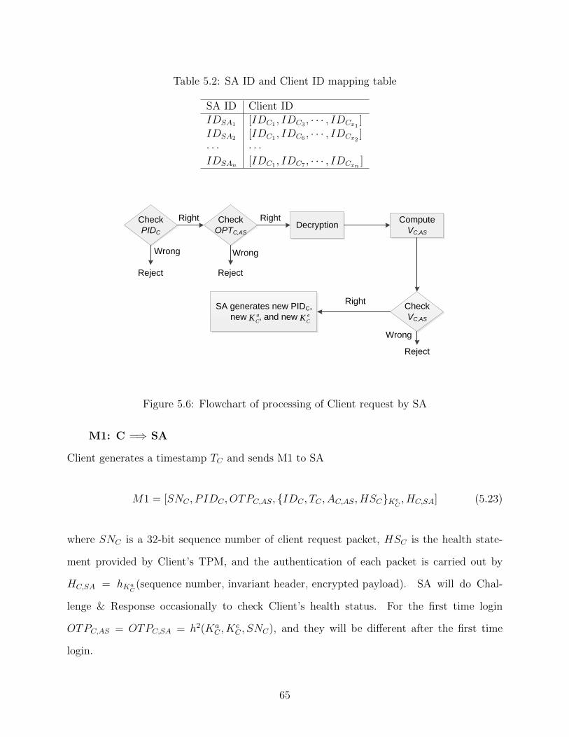
Table 5.2: SA ID and Client ID mapping table
SA ID Client IDIDSA1 [IDC1 , IDC3 , · · · , IDCx1
]IDSA2 [IDC1 , IDC6 , · · · , IDCx2
]· · · · · ·IDSAn [IDC1 , IDC7 , · · · , IDCxn
]
Check
PIDC
Check
OPTC,ASDecryption
Compute
VC,AS
Check
VC,AS
SA generates new PIDC,
new , and new e
CKa
CK
Wrong Wrong
Reject Reject
Right Right
Wrong
Right
Reject
Figure 5.6: Flowchart of processing of Client request by SA
M1: C =⇒ SA
Client generates a timestamp TC and sends M1 to SA
M1 = [SNC , P IDC , OTPC,AS, {IDC , TC , AC,AS, HSC}KeC, HC,SA] (5.23)
where SNC is a 32-bit sequence number of client request packet, HSC is the health state-
ment provided by Client’s TPM, and the authentication of each packet is carried out by
HC,SA = hKaC
(sequence number, invariant header, encrypted payload). SA will do Chal-
lenge & Response occasionally to check Client’s health status. For the first time login
OTPC,AS = OTPC,SA = h2(KaC , K
eC , SNC), and they will be different after the first time
login.
65

After receiving the login request from client, SA processes the request based on the
flowchart in Fig. 5.6. If any stage of the request fails, the request will be rejected immediately
and the packet is discarded. Otherwise, if the request is from a legitimate user, SA computes
OTPSA,C , generates new KaC and new Ke
C for next authentication session, and delivers to
Client and AS respectively.
new KaC = h2(IDC , hAS,SSA,C , new TC , “Client AUTH”) (5.24)
new KeC = h2(IDC , hAS,SSA,C , new TC , “Client ENCR”) (5.25)
M2: C ⇐= SA
After computing the new KaC and new Ke
C , SA sends M2 to Client
M2 = [SNSA, OTPSA,C , {new PIDC , new KaC , new Ke
C}KeC, HC,SA] (5.26)
Clients computes and checks OTPSA,C . If it is correct, it will decrypt and get new PIDC
and new keys for next login.
M3: SA =⇒ AS
SA also sends M3 to AS
M3 = [IDC , TC , AC,AS, new PIDC , new KaC , new Ke
C ]KeC
(5.27)
AS stores the new PIDC , new authentication key KaC and new encryption key Ke
C . The
activity should be logged by AS.
M4: C =⇒ SA
The payload is encrypted using the encryption key KeC together with the IDC , new TC , and
new VC,AS.
M4 = [SNC , P IDC , OTPC,SA, {IDC , new TC , new VC,AS, payload}KeC, HC,SA] (5.28)
66

where new TC is the new timestamp generated by Client, and SNC is the request sequence
number. After received the packet, SA first checks PIDC . If PIDC is right then it proceeds
to compute OTPC,SA = h2(KaC , K
eC , SNC) and checks if the OPTC,SA matches the received
one. If either one in the above two fails, the request is rejected immediately. Only when
both PIDC and OTPC,SA can be verified, the payload is decrypted and SA sends new TC
and new VC,AS to AS.
A secure tunnel is established after successful mutual authentication. Each direction of
the flow in a tunnel has a 32-bit sequence number as the counter of sent packets. The authen-
tication of each packet is carried out byHC,SA = hKaC
(SN, invariant header, encrypted payload).
Moreover, SA establishes a secure tunnel to other SA in order to let User receive the service
(SA requests ticket on behalf of User). After Client login, every packet should be authen-
ticated. Every packet has a 32-bit sequence number (SN) in clear text header. Re-login
of Client is required when SN is about to wraparound. Sender, either C or SA, uses the
following fresh keys for every packet
KaC∗ = h2(PIDC , K
aC , SN, “Client AUTH”) where SN = SNC or SNSA (5.29)
KeC∗ = h2(PIDC , K
eC , SN, “Client ENCR”) where SN = SNC or SNSA (5.30)
The destination IP address is protected similar to ESP [49].
5.3.2 User and SA Authentication
User authentication occurs after Client authentication and establishes a secure tunnel
inside the C-SA tunnel for accessing critical information. The process User or SA authentica-
tion is very similar to Client authentication, changing the corresponding ID and timestamp.
A secure tunnel is established after successful SA mutual authentication. Each direction
of the flow in a tunnel has a 32-bit sequence number as the counter of sent packets. The
67

authentication of each packet is carried out by HSA,SSA. After SA login, every packet needs
to be authenticated. Re-login is of SA is required when SN is about to wraparound.
5.4 Summary
In this chapter, the space-time evolving authentication scheme is presented. The system
includes user, client host, security agent, super security agent, authentication server and
database server. The security agent acts as a proxy between a client and other servers.
It monitors and tracks the state transitions in ACL, and authenticate user and process
according to ACL and AD (Active Directory). The super security agent coordinates a group
of security agents. It monitors the health of security agents and track state transition in
ACL. The space-time evolving concept is adopt to enhance the system securities. Only the
owner of the key can derive the key for the next authentication session, while the parties
involved can only verify the key. The registration and mutual authentication process are
illustrated step by step. Once the mutual authentication process is finished, a secure tunnel
is established inside Client-SA for user to communication with remote servers.
68

Chapter 6
Correlation Engine and Real-Time Forensics
6.1 Access Control List (ACL)
Access Control List (ACL) is used widely to control and grant access to certain objects
in the computer systems. For each object, there is a list of permissions and operations that
are allowed. We use Extensible Markup Language (XML) to define our ACL (see Fig. 6.1
for an example of ACL rule).
To control the access, the following components are used in our ACL (see Table 6.1).
Entry SoH is the state of health, which is used to check if there are any modifications
of current system and applications. Application ID (AppID) contains the credentials of an
application, such as HMAC. Content ID contains comprehensive URL database and elements
of application identification to limit unauthorized information transfer plus HMAC.
Fig. 6.2 illustrates the role and capability based access control. The subject on behalf
of a user with a role’s indicator will possess the necessary capabilities required by the role’s
responsibility. Upon execution of the program file or domain transition, the subject’s capabil-
ity state is recalculated based on the current security context. Note that the security context
involves the program file being executed, the current role and the current domain. Based
on the validity check conditions for an execute request, security manager verifies whether
Table 6.1: Components in the ACL
Username NetworkProtocol
NetworkPath
Src IPaddress
Dst IPAddress
HostType
Host OSID
Time CurrentAppID
ParentAppID
ContentID
HMAC PID SoH
69

<rule id="match.rule.1">
<eventType> Logfile_Base </eventType>
<match>
<predicate>
<![CDATA[&hostname == “client1"]]>
</predicate>
</match>
< triggerActions>
<action function="Discard"/>
</triggerActions >
</rule>
Figure 6.1: XML definition of an ACL rule
User Role Domain Capability Task
Subjects
SID/
Object
Map
Security
Manager
Object Manager
Figure 6.2: Role and capability access control
70

the mediation for the subject’s current security context and capability state is valid. If the
validity of the execute request has been verified by the algorithm, the appropriate process
image, role, domain and capability state corresponding to this subject will be created or
mediated.
To illustrate how ACL works in SA, SSA and AS (see Fig. 5.1), we give an example for
Client’s AJAX request. SA, SSA and AS with ACL verify Client’s request according to ACL
based on username, source/destination IP addresses, network path, time, AJAX script ID,
parent AppID, and query field in the form. Moreover, they also verify inconsistency with
currently active ACL (within a time interval) 1) nested/chained commands for accessing a
target, involving multiple hosts, usernames, and applications; 2) one user in two separate
locations at the same time; 3) modification/creation/deletion of logs. Authorization request
is triggered if ACL requires the permission from SSA for critical information.
6.2 Logs Creation and Protection
Logs are the key information needed to correlate attacks and generate forensics report.
All the related activities should be logged in User/Client, SA, SSA, AS and DS. Correlation
Engine will collect the required logs from all the related entities.
6.2.1 Log Format
Maintaining a log with records for each packet received over an infinite period of time
would be prohibitively expensive and time-consuming. Therefore, each SA and SSA main-
tains log records based on a sliding time window of length t, say t = 15 minutes. Logs are
maintained for the most recent t time of traffic for fast availability; older logs are stored on
a backup server.
The format of these log records is shown in Fig. 6.3. The record contains standard
packet data such as source and destination IP addresses, packet sequence number, and
packet arrival time. The record also contains the current and parent application IDs, which
71
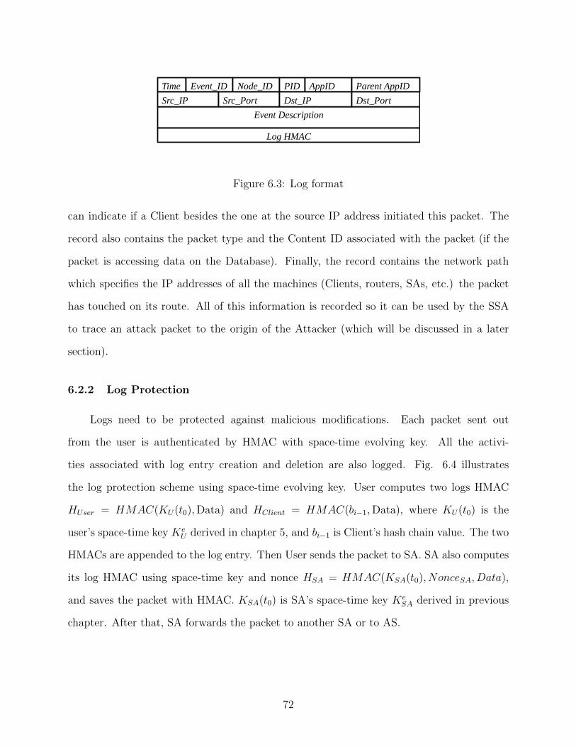
Time Event_ID Node_ID PID AppID Parent AppID
Event Description
Log HMAC
Src_IP Src_Port Dst_IP Dst_Port
Figure 6.3: Log format
can indicate if a Client besides the one at the source IP address initiated this packet. The
record also contains the packet type and the Content ID associated with the packet (if the
packet is accessing data on the Database). Finally, the record contains the network path
which specifies the IP addresses of all the machines (Clients, routers, SAs, etc.) the packet
has touched on its route. All of this information is recorded so it can be used by the SSA
to trace an attack packet to the origin of the Attacker (which will be discussed in a later
section).
6.2.2 Log Protection
Logs need to be protected against malicious modifications. Each packet sent out
from the user is authenticated by HMAC with space-time evolving key. All the activi-
ties associated with log entry creation and deletion are also logged. Fig. 6.4 illustrates
the log protection scheme using space-time evolving key. User computes two logs HMAC
HUser = HMAC(KU(t0),Data) and HClient = HMAC(bi−1,Data), where KU(t0) is the
user’s space-time key KeU derived in chapter 5, and bi−1 is Client’s hash chain value. The two
HMACs are appended to the log entry. Then User sends the packet to SA. SA also computes
its log HMAC using space-time key and nonce HSA = HMAC(KSA(t0), NonceSA, Data),
and saves the packet with HMAC. KSA(t0) is SA’s space-time key KeSA derived in previous
chapter. After that, SA forwards the packet to another SA or to AS.
72

SA1. User computes two HMAC Huser, Hclient , and add log/log creation log
3. SA computes HMAC hSA, saves the packet with HMAC as log
4. Forward the packetHuser = HMAC(Ku(t0), Packet)
Hclient = HMAC(bi-1, Packet)HSA = HMAC(KSA(t0), NonceSA, Packet)
Packet
Time PID AppID Packet Huser Hclient
Time Log entry creation Hclient
2. Send the packet to SA
Time Packet Huser HSA
Time Log entry creation HSA
PseudoID
t t
t0
Figure 6.4: Log protection scheme
73

Figure 6.5: Attack chain from outside attacker
6.3 Correlation Engine and Real-Time Forensics
6.3.1 Correlation Engine
We use the event corresponding to the failure to attack critical resources as a starting
point. Related logs are retrieved and analyzed. Correlation Engine (CE) traces the attack
from the attack path to root attackers (see Fig. 6.5). A record contains root[ip,port,hostname,attack
chain],time are generated to assist forensics processing. At every transition host in the at-
tack path, analyze the inconsistencies and violations based on state transition diagram and
privilege transition diagram. CE detection rules are as follows:
• Authentication failure: Compare timestamps in authentication failure logs. At a given
time T , there are more than C (such as C = 3) authentication failure logs.
• Illegal privilege escalation: Analyze privilege related logs and check if there is any
privilege escalation.
• State transition violation: Maintain state ID, Sid, and state transition diagram, and
check if there is any violation with ACL.
• Loation/time inconsistency: Check if there is any location/time inconsistency.
6.3.2 Real-Time Forensics
All the log data and traffic data are stored in the database on the forensics security
agent. The survey data are also saved in the agent. All these data will give guidance to
the forensics analysis, data mining analysis, investigation target profiles, emergence response
policy and even IDS signature pattern.
74

Super security agents integrate the forensics data and analyze them. It also guides the
network packet filter and captures the behavior on the network monitor. It can launch the
investigation program on the network investigator as the response to the sensitive attacks.
Network security agents are engines of the data gathering, data extraction and data
secure transportation. It also gives the mechanism of digital signature to data integration,
communication, command and control. Agents resident on the monitored host, and network
log includes the possible misuse and potential risk origin in the network. System log includes
the change of the register, file system, system directory, system process, open ports and
system services. Important files include the evidence of misuse behavior. This data is useful
to find the compromise procedure and discover the evidence of intrusion.
The network traffic data is fully captured to record the whole procedure of the intrusion
and can be used to reconstruct the intrusion behavior. The main function of the security
agent is obtaining information of some sensitive spots on the malicious list. The lists are
imported from the analysis of forensics data and given by the super security agent. This
function can be executed automatically. Surveying the domain name of an IP address will
give some details of the origin of the malicious attacker. DNS surveying can acquire some
useful information, such as location, email address, and phone number. Many tools are
integrated in the system, such as ping, traceroute, nslookup, whois and so on.
LogDB stores the sensitive data gathered from the distributed TPMs. It can provide
sensitive knowledge for the network monitor machine to pursue adaptive packet filtering and
capture. TrafficDB are the data transformed from the raw network traffic captured by the
network monitor machine. They are evidence of the network behavior on monitored host.
Some data mining approaches can be used on network forensics analysis. Data mining
generally refers to the process of extracting models from large stores of data. We choose
several algorithms in our research. Classification analysis can map a data item into one of
several predefined categories. Link analysis will determine relationship between fields in the
database. Finding out the correlations in forensics data will provide insight for discovering
75

attack behavior, for example, sequence analysis can help us understand the sequence of
forensics events.
The survey result includes the intranet mapping topology data, which will be used
for the intranet misuse trace back. The intranet mapping data includes IP address, MAC
address, user name, geographic room number, email address and so on. Survey results can
also include some internet survey data, such as domain name, possible geographic location,
IP address, MAC address, phone number, email address, possible OS types and so on.
Presentation gives the statistics of the most possible attacking time, time span, penetrate
tools, hacker techniques, IP address, the origin country of the attacker, attacking hops and
so on. Some attacking characteristics can be estimated by the system, such as OS system
and geographic location.
The forensics report is generated based on the event analysis and event correlation. It
contains
• The activities associated with the user.
• The type of attacks launched.
• The location of attacks launched.
• The target of attacks.
• The location of log tampered.
• The asset was accessed.
• The flow of critical data.
• The space and time evolution of events that can be found, linked by consequence and
proximity of space and time.
76
6.3.3 Network Topology Mapping
Another function is to scan the network for mapping topology. Mapping topology of
the network may help to find fraudulent proxy server, ARP spoofing and trace back the
location of the attack origin. Mapping the topology of the local area network will help to
find the origin of the misuse behavior. The scan and survey result includes the topology of the
network, the IP address, the MAC address, the possible geographic location of the IP, domain
name, phone number, email address, possible OS types. IP trace back and mapping the IP
to the geographic location are the most important approaches in the network investigator.
The response is real time, so that once the IDS gives the alert, the network forensics server
will send the command to the network investigator. Another approach that can be used is
remote OS fingerprinting. It can obtain the general OS type of the target host. This is useful
to estimate the experience level and the possible attack tools of the investigated object. The
result also can serve as a digital evidence for future forensics. We can use nmap tools in the
OS fingerprinting scan.
6.3.4 Traceback Root Attackers
When the intruder attempts to steal critical information, it will be caught in real-time.
From the failure point, traceback procedure is taken to trace the root attackers. The attack
traceback capability is two-fold: first, it can identify the origin of any detected attack, and
second, it can detect all Slave Clients controlled by the attacker. When an attack is detected,
a report is sent by the detecting SA or SSA to one of the SSAs. This SSA then initiates a
traceback process to identify to source of the attack.
6.4 Summary
Logs are is the key to traceback the attacker. Some intruders may try to tamper the log
to hide their activities. Thus, the logs of all involved parties are protected using the space-
time evolving key. If there is any intrusion detected by the space-time authentication scheme,
77

or any violations of ACL, the correlation engine is trigger to traceback the attacker. The
forensics report is generated based on the event analysis and event correlation. It includes
the type of attack, the activities associate with the user, the flow of critical data, etc. The
damage is also assessed and a recovery process is followed.
78

Chapter 7
Performance Evaluation for Proposed Space-Time Evolving Authentication Scheme
7.1 Active Attack Chain
It is necessary to demonstrate how the proposed scheme defends against various attacks.
In general, it will be assumed that attacks will either seek to read sensitive information from
the Database or overwrite sensitive information on the Database. Based on this assumption,
several general attack scenarios can be formed and their likelihood of success measured
against the security of the network.
The attacks can be classified into two types based on their approach (See Fig. 7.1).
The inside attack launches attack to the critical resources directly inside the organization.
The outside attack first compromises some Client Hosts inside the organization. A group
of these Client Hosts form a “botnet”. When an outside attacker launches their attack, it
coordinates some comprised hosts as active attack path. An attacker may choose to use
one or more compromised hosts to launch an attack in order to 1) make use of their login
credentials, and 2) mask his own identity.
If the outside attack chain is greater than two or the inside attack is greater than one, the
compromised host controls a group of hosts. The attack chain starts from the compromised
hosts and selects attack path from hosts in its control.
There are three stages in the attack (see Fig. 7.2). First, the attacker scans the vul-
nerabilities inside an organization. If the security policy is loose, it is easy for attackers
to penetrate into the network and compromise some hosts. In our implementation, we use
either BufferOverflow or Phishing attack in this stage. Second, The outside attacker targets
certain compromised hosts and uses them to send request to DS. In this stage, SQL Injection
attack is used. Different SQL injection attack methods are tried to gain access to DS and
79

Figure 7.1: Two different approaches of attack
BufferOverflow
Host A
Stage IPrepare Stage
Stage IIAttack Stage
Stage IIIConsequence Stage
Start
attacks
Host A
SQL Injection
Try different SQL injection attacks
All the logs are protected and later used by CE
Start
attacks
Consequence
Unsuccessful-If attack fails for more than three times in a time
threshold-If request violates the ACL
Successful-Execute SQL-May get some information
-Authentication failure later
Trigger
CE
Figure 7.2: Three stages of attack
80

to retrieve critical information. All activities will be logged and protected. The logs will
be used by CE (Correlation Engine) later. Third, there are two types of consequences in
this stage, unsuccessful and successful. Unsuccessful attack means either an attack fails for
more than three times in a time threshold, or the request violates the ACL. While successful
attack means SQL query can be executed and may get some information. However, in the
outgoing SA (there are two SAs in front end of critical resources, incoming and outgoing
SA), the content and privilege will be checked based on the ACL. If the request cannot prove
possession of right credential, the information cannot be retrieved outside the DS. If there
is any violation or authentication failure in the above case, the CE is triggered and forensics
processing is followed.
7.2 Network Model
We consider a network NE = (SD, SA, H), where SD is the set of security agents which
are referred to as defenders, and SA is the set of attackers. H = (1, 2, · · · , Nh) is the
set of network host which may be attacked by the attackers, referred to as targets, and
A = (1, 2, · · · , Na) is the set of root attacker which is the source of all attacks.
The object of the attacker is to attack the targets and gain critical resources without
being detected. p = (p1, p2, · · · , pNh) is the attack probability distribution over the target
host set H, where pi is the probability of successfully attacking target i.∑
i∈H pi ≤ P ≤ 1
represents the attackers’ resource constraint.
In order to detect the attacks, SA monitors the target hosts with the probability q =
(q1, q2, · · · , qNh), where qi is the probability of monitoring target i. Monitor means that the
defender security agent collects audit data and examines them for signs of security problems.
We have∑
i∈H qi ≤ Q ≤ 1 that represents the defender’s monitor resource constraint.
We setup a hierarchical network topology (see Fig. 7.3), which consists of host, star and
group. Each star contains 100 hosts and each group has 10 stars. If we want to simulate
81

Figure 7.3: Network topology
a network of an organization with hosts [1k, 5k, 10k, 15k, 20k, 25k, 30k, 35k], then we have
stars of [10, 50, 100, 150, 200, 250, 300, 350] and group of [1, 5, 10, 15, 20, 25, 30, 35].
7.3 Simulation Results
7.3.1 Fixed Attack Ratio
In this simulation scenario, we fix the attack ratio. Assume there are total of Nhost hosts
inside an organization. We set the ratio of hosts that are under attack to be AttRatio = 0.3,
and ratio of the compromised hosts that are under attack to be ComRatio = 0.1.
During all simulations, background traffic was introduced into the network in order to
simulate normal operating conditions. It was determined that introducing network traffic on
the slower network connections did not affect the simulation results (and made the simulation
running time prohibitively long). Therefore, all background traffic was introduced between
the SAs and the SSAs. Background traffic equal to 625 kbps/Client was divided equally
between SAs and the SSAs and sent from each SA to each SSA. An equal amount of traffic
was sent from each SSA to each SA. This rate of background traffic ranged from a one-
way 80% load on a 10 Gbps link for a full-sized network (35k Clients) to a much smaller
load for smaller networks (0.8% load for a 1000 Client-network). This rate of background
traffic affected both log search time during Attack Tracebacks (background traffic increased
82

a) Inside attack identify attack time b) Inside attack detect all compromised hosts time
c) Outside attack identify attack time d) Outside attack detect all compromised hosts time
Figure 7.4: Network topology
the number of log entries) and packet transit time in the Data Center (due to network
congestion).
During the simulations, one of the statistics tracked was the Traceback time. Each
time an attack was detected, the simulation time was recorded as T1 for that attack. When
the SSA completed the traceback to identify the attacker, that time was recorded as T2.
When the SSA completed the log search to identify all Slaves of that Attacker, that time
was recorded as T3. These three times were used to compile statistics about the traceback
speed of the IDACS system (which are shown in the following graphs). The two times of
83

interest are the traceback time (T2 − T1) and the All Slaves Identified time (T3 − T1). It
should be noted that for any given attack, (T2−T1) will always be shorter than (T3−T1),
since (T3− T1) = (T2− T1) + (T3− T2).
One of the advantages of our system is its ability to identify the attacker and all the
compromised hosts quickly. Fig. 7.4 shows the traceback response time for both inside
attack and outside attack specified in the beginning of this chapter. We can see that attack
traceback times are very short, with even the (T3 - T1) traceback time under 4 milliseconds.
Even as the network size grows, the traceback time grows very slowly relative to the network
size. This is because the simulation uses log2(n) (n is the size of the network) to calculate
log search time, since there are currently log search methods that are better than log2(n).
Because the attack traceback is so fast, our system can begin defensive or counterattack
procedures before the attacker even realizes that the attack has been detected and blocked.
7.3.2 Fixed Root Attacker
In this simulation scenario, we fix the root attackers numbers. The attacks from root
attacker consist of two phases. First, the root attacker scans the vulnerabilities of the target
network. If there are any security holes, such hosts with vulnerabilities are compromised and
under control by root attacker. Second, it coordinates an attack chain (in our simulations,
we set the attack chain to be 2, 3 and 4). The attack chain means the path from root
attacker to target resources (see Figure 7.1). As the number of root attackers increases, the
number of compromised hosts increases exponentially.
The attacks can be very sophisticated using different kind of attacks, such as SQL
injection, buffer overflow, cross-site scripting (XSS), and phishing attacks. Moreover, it
adopts different attack path, and sometimes it can even bypass the security check of SA.
Fig. 7.5 shows the detection ratio of root attackers. As the root attackers increase, the
detection ratio decreases a little bit because the number of compromised hosts increases
84

a) Number of root attacker: 16 b) Number of root attacker: 32
c) Number of root attacker: 64 d) Number of root attacker: 128
Figure 7.5: Detection ratio of root attacker
85

exponentially. Even with 128 root attackers and in a network of 35k hosts, our detection
ratio is still above 97%.
If the attack packet did not possess the proper authentication or authorization param-
eters, any SA or SSA would detect the attack 100% of the time. In reality, however, some
attacks would go undetected due to various attack methods (SQL injection, buffer overflow,
etc.) Therefore, the security checks performed by the SAs and the SSA were governed by
a set of ”Fail to Detect Attack” probabilities. For example, if an attack packet failed the
authorization check at a given SA, the outcome of this failure would be governed by a ”Fail
to Detect Attack” probability variable. If the variable was set to 50%, then there would be a
0.5 chance that the SA would still pass the attack packet through as if it had failed to detect
the attack. This was done for two reasons. First, as mentioned earlier, this situation more
closely reflects reality. Second, this situation can be used to demonstrate the performance of
our system even if several barrier machines are compromised. As mentioned in the ”Attack
Scenarios” section, it is possible for any SA or SSA to be compromised by an attacker and
forced to allow attack packets to pass through. Such a situation is reflected by adjusting the
”Fail to Detect Attack” variable to 100%. In this simulation, normally functioning SAs and
SSAs had these ”Fail to Detect Attack” variables set to 0.5. This was done to demonstrate
the strength of our system, even under ”poor” performance conditions (in reality, this prob-
ability is expected to be much lower than 0.5), and also to allow some attacks to succeed in
order to see the effect of other variables on network performance.
7.4 Summary
To evaluate the performance of proposed space-time evolving authentication scheme,
simulations are carried out in different scenarios. The network increases from 1,000 hosts to
35,000 hosts. As the root attackers increase, the detection ratio decreases a little bit because
the number of compromised hosts increases exponentially. Even with 128 root attackers and
in a network of 35k hosts, our detection ratio is still above 97%. The simulation results of
86

correlation response time and detections ratio are both satisfactory. Part of the research is
published on IEEE TrustCom 2011 [53].
87

Chapter 8
Conclusion and Future Work
With the rapid increase of security breaches into corporate networks, it is important
to protect critical information against intruders. There are many variations of attacks and
new forms of attack are still emerging, such as metamorphic and polymorphic malwares,
zero-day attacks, and Boot Record malwares. The current protection schemes against unau-
thorized intrusions have some weaknesses and cannot protect the network efficiently and
thoroughly. To protect the network against intrusion and DoS/DDoS attacks and provide
real-time forensics, two security systems are proposed in this dissertation.
The first approach is an intrusion resilient, DDoS-resistant authentication system (IDAS).
The IDAS system protects the network via time-dependent secret and self-healing properties
of hash chain. We also distribute two-factor user secret using two HMACs and distribute the
authentication server into two authentication servers. By using these methods, even strong
adversaries can be detected and rejected immediately without influencing the performance
of the current network. To demonstrate the performance, we carried out simulations from
small scale inside a building to large scale like coast to coast and continent to continent.
The simulation results suggest our proposed system is fast and efficient against intrusion
and DDoS attacks.
The second approach is built upon the existing security technology and reduces its weak-
ness. The center of the research is to guard critical information/resource against intrusion,
and provide real-time forensics. The approach provides the last line of defense against theft
of critical information/resource. We accomplish the intrusion detection and prevention using
the innovative method
• Use the attempts of stealing the critical information as the entry point.
88

• Use an innovative ACL (Access Control List)
• Use a space-time evolving authentication scheme, including user, process, parent pro-
cess, application, behavior, and guarded information/resource.
Moreover, this approach will also provide real-time forensics to help failure points recovery.
• Use a space-time evolving scheme to acquire and guard logs. The keys for log protection
are changing from time to time, location to location.
• Violation of ACL (Access Control List) will trigger correlation engine.
• Real-time correlation of possible events to identify attack, attacker, damage (including
lost information, servers, hosts and devices). The detailed forensics report will cover
attack location, time, type of attack, type of target, etc.
Nevertheless, there are still some limitations and assumptions in the investigation on
the proposed security systems, and we wish to further explore the challenges and problems
in the near future.
• It is difficult to prove the capabilities of IDAS by actually implementing a full scale
botnet due to financial constraints. In this dissertation, only simulation results are
reported. In practice, we implement the system using Java in a laboratory setting
with several computers. In the future, we may cooperate with big companies from
industry to carry out large scale testing in real environments. Part of the research in
this dissertation is sponsored by Northrop Grumman Corporation (NGC). In the first
stage, the security systems are implemented using six computers, and are tested in
large scale via simulation. As the simulation results are encouraging, NGC proposes
to test the system in a real environment. There are hundreds of thousands hosts in
NGC’s Information Security Lab, which makes the test possible in the future.
• Distributing the server and secret enhances the system security and performance. We
may distribute the authentication server to a bank of servers in different locations. In
89
the two-servers case of the proposed IDAS solution, the authentication services could
be distributed to different locations, each location has two servers. The nearest in
geographic location or the least utilized servers are chosen based on the request. By
distributing the authentication servers, the authentication services could be guaranteed
even when certain authentication servers are overwhelmed by coordinated large scale
attacks. In this case, if the current authentication servers could not respond, the
authentication request can be routed to another location.
• As many entities are involved in our system, the synchronization process is challenging.
In this disssertation, Network Time Protocol (NTP) is chosen to synchronize the sys-
tem. However, there are some limitations on this method. We would like to investigate
more synchronization methods. Every request has its corresponding sequence number.
The protected sequence number could be used to synchronize the service between a
client host and an authentication server. Moreover, a beacon could be added in the
request packet to indicate the status of the current request. These methods could
be investigated in the near future to compare the performance and security with the
current scheme.
90

Bibliography
[1] Chronology of Data Breaches, http://www.privacyrights.org/data-breach#CP.
[2] CNET, http://news.cnet.com/8301-1009_3-10152246-83.html.
[3] Verizon RISK Team, “2011 Data Breach Investigation Report,” Verizon Business, 2011.
[4] M. Long, C.-H. Wu and J. D. Irwin, “Localized authentication for wireless LAN inter-network roaming,” In Proc. of IEEE Wireless Communication and Networking, Atlanta,GA, USA, Mar. 2004.
[5] W. Aiello, S. M. Bellovin, M. Blaze, R. Canetti, J. Ioannidis, A. D. Keromytis, andO. Reingold, “Just fast keying: Key agreement in a hostile internet,” ACM Trans. Inf.Syst. Secur., 7(2):242-273, 2004.
[6] T. Saito, R. Hatsugai, and T. Kito, “On compromising password-based authenticationover HTTPS,” in Proceedings of 20th International Conference on Advanced Informa-tion Networking and Applications, 2006, vol. 1, pp. 869-974.
[7] Y. Shiraishi, Y. Fukuta, and M. Moril, “Port randomized VPN by mobile codes,” inProc. of First IEEE Consumer Communications and Networking Conference, 2004, pp.671 673.
[8] Internet Key Exchange (IKE), RFC 2409.
[9] J. G. Steiner, C. Neuman, “Kerberos: An authentication service for open networksystems,” in Proc of Winter USENIX Conference, 1988.
[10] J. Franks, P. Hallam-Baker, J. Hostetler, S. Lawrence, P. Leach, A. Luotonen, and L.Stewart, “HTTP authentication: basic and digest access authentication,” RFC2617,June 1999.
[11] Song, D. dsniff. http://naughty.monkey.org/dugsong/dsniff/
[12] H. Xia and J. C. Brustoloni, “Hardening Web browsers against man-in-the-middle andeavesdropping attacks,” in Proceedings of the 14th International Conference on WorldWide Web, 2005, pp. 489-498.
[13] R. Dhamija, J. D. Tygar, and M. Hearst, “Security: Why phishing works,” in Pro-ceedings of the SIGCHI conference on Human Factors in computing systems, 2006, pp.581-590.
91

[14] A.Y. Fu, X. Deng, L. Wenyin, and G. Little, “Catching phish: The methodology and anapplication to fight against Unicode attacks,” in Proceedings of the Second Symposiumon Usable privacy and security, 2006, pp. 435-437.
[15] C.-H. Wang, C.-W. Yu, C.-K. Liang, K.-M. Yu, W. Ouyang, C.-H. Hsu, and Y.-G.Chen, “Tracers placement for IP traceback against DDoS attacks,” in Proceeding of the2006 International Conference on Communications and Mobile Computing, 2006, pp.355-360.
[16] D. G. Andersen, “Mayday: Distributed filtering for internet services,” in Proceedingsof the 4th USENIX Symposium on Internet Technologies and Systems, 2003, p. 39-44.
[17] H. Lohr, A.-R. Sadeghi, M. Winandy, “Patterns for Secure boot and secure storagein computer systems,” in Proc. of Int. Conf. on Availability, Reliability, and Security(ARES’10), Krakow, Poland, Feb. 2010.
[18] D. Keromytis, V. Misra, and D. Rubenstein, “SOS: Secure overlay services,” in Pro-ceedings of ACM SIGCOMM, 2002, pp. 61-72.
[19] W. G. Morein, A. Stavrou, D. L. Cook, A. D. Keromytis, V. Misr, and D. Ruben-stein, “DOS protection: Using graphic turing tests to counter automated DDoS attacksagainst web servers,” in Proceedings of the 10th ACM Conference on Computer andCommunications Security, 2003, pp. 8-19.
[20] A. Stavrou, A. D. Kermytis, “Intrusion detection and prevention: Countering DoSattacks with stateless multipath overlays,” in Proceedings of the 12th ACM Conferenceon Computer and Communications Security, 2005, pp. 249-259.
[21] H. Farhat, “Protecting TCP services from denial of service attacks,” in Proceedingsof the 2006 SIGCOMM Workshop on Large-Scale Attack Defense LSAD, 2006, pp.155-160.
[22] Snoeren, C. Partridge, L. A. Sanchez, C. E. Jones, F. Tchakountio, B. Schwartz, S.T. Kent, and W. T. Strayer, “Single-packet ip traceback,” IEEE/ACM Trans. Netw.,10(6):721-734, 2002.
[23] Y. Shiraishi, Y. Fukuta, and M. Moril, “Port randomized VPN by mobile codes,” inProceedings from First IEEE Consumer Communications and Networking Conference,2004, pp. 671-673.
[24] L. Lamport, “Password authentication with insecure communication,” Communicationsof the ACM, vol. 24, no. 11, Nov. 1981, pp. 770-772.
[25] J. Menezes, P. C. van Oorschot, and S. A. Vanstone, Handbook of Applied Cryptogra-phy, CRC Press, Florida, USA, 1996.
[26] M. Long, and C.-H. Wu, “Energy-efficient and intrusion-resilient authentication forubiquitous access to factory floor information,” IEEE Transactions on Industrial Infor-matics, vol. 2, issue 1, pp. 40-47, Feb. 2006.
92
[27] H. Shoacham, D. Boneh, E. Rescorla, “Client-side caching for TLS,” ACM Transactionson information and System Security, vol. 7, no. 4, November 2004.
[28] Y. Yang, R. Deng, and F. Bao, “A practical password-based two-server authenticationand key exchange system,” IEEE Transactions on Dependable and Secure Computing,vol. 3, issue 2, pp. 105 - 114, April-June 2006.
[29] H. Krawczyk, M. Bellare, and R. Canetti, “HMAC: Keyed-hashing for message authen-ticaion,” RFC 2104, 1997.
[30] Michael Glenn, “A summary of DoS/DDoS prevention, monitoring, and mitigationtechniques in a service provider environment,” SANS Institute, 2003
[31] D. Moore, V. M. Geoffrey and S. Stefan, “Inferring Internet denial-of-service activity,”,in Proceedings of the 10th USENET Security Symposium, Washington, D.C., USA,July 2003.
[32] D. Moore, P. Vern, S. Stefan, S. Colleen, S. Stuart and W. Nicholas, “The spreadof the Sapphire/Slammer worm,”, Cooperative Association for Internet Data Analysis(CAIDA), July 2003.
[33] B. Zhu and A. A. Ghorbani. “Alert correlation for extracting attack strategies,” Inter-national Journal of Network Security, 3(2):244-258, 2006.
[34] D. E. Denning, “An intrusion-detection model,” IEEE Transactions on Software Engi-neering, 13(2):222-232, 1987.
[35] D. V. Forte. “The art of log correlation,” in Proceedings of the Information SecuritySouth Africa (ISSA) 2004 Enabling Tomorrow Conference, July 2004.
[36] P. Ning, Y. Cui, D. S. Reeves, and D. Xu, “Techniques and tools for analyzing intrusionalerts,” ACM Transactions on Information and System Security (TISSEC), 7(2):274-318, 2004,
[37] S. T. Eckmann, G. Vigna and R. A. Kemmerer, “Statl: An attack language for state-based intrusion detection,” in Processings of the 1st ACM Workshop on Intrusion De-tection Systems, Athens, Greece, November 2000.
[38] F. Cuppens and R. Ortalo, “Lambda: A language to model a database for detectionof attacks,” in Processings of 3rd International Symposium on Recent Advances inIntrusion Detection, Toulouse, France, October 2000.
[39] O. M. Dain and R. K. Cunningham, “Fusing a heterogeneous alert stream into scenar-ios,” in Proceedings of the 2001 ACM Workshop on Data Mining for Security Applica-tions, 2001.
[40] F. Baskett, K. M. Chandy, R. R. Muntz and F. C. Palacios, “Open, closed and mixednetworks of queues with different classes of customers,” Journal of ACM, 22(2):248-260,1975.
93

[41] P. Ning, Y. Cui, and D. S. Reeves, “Constructing attack scenarios through correlationof intrusion alerts,” in Proceedings of 9th ACM Conference on Computer and Commu-nication Security (CCS), Washington D. C., USA, November 2002.
[42] R. Jain, “The Art of Computer Systems Performance Analysis: Techniques for Exper-imental Design, Measurement, Simulation, and Modeling,” Wiley- Interscience, NewYork, NY, April 1991, ISBN:0471503361.
[43] K. Levitt and S. J. Templeton, “A requires/provides model for computer attacks,” inProceedings of the 2000 Workshop on New Security Paradigms, February 2001.
[44] R. O. Onvural, “Survey of closed queueing networks with blocking,” ACM ComputingSurvey, 22(2):83-121, 1990.
[45] F. Cuppens and A. Miege, “Alert correlation in a cooperative intrusion detection frame-work,” in Proceedings of IEEE 2002 Symposium on Security and Privacy, 2002.
[46] G. Casale, N. Mi, E. Smirni, ”Bound Analysis of Closed Queueing Networks with Work-load Burstiness” in Proc. of ACM SIGMETRICS 2008, 13-24, Annapolis, MD, ACMPress, June 2008.
[47] P. Owezarski, “On the impact of DoS attacks on Internet traffic characteristics andQoS,” In Proc. of 14th International Conference on Computer Communications andNetworks, ICCCN 2005, pp. 268-274.
[48] Network Time Protocol, www.ntp.org
[49] S. Kent, R. Atkinson, (November 1998), “IP Encapsulating Security Payload (ESP),”IETF RFC 2406.
[50] T. Liu and C.-H. Wu, “Intrusion-resilient, DDoS-resistant and agent-assisted networksecurity system,” in Proc. 4th International Conference on Broadband Communications,Networks, and Systems (BROADNETS’07), Raleigh, NC, USA, September 2007.
[51] C.-H. Wu and T. Liu, “Simulation for intrusion-resilient, DDoS-resistant authenticationsystem (IDAS),” in Proc. of ACM Spring Simulation Multiconference (SpringSim’08),Ottawa, Canada, April 2008.
[52] C.-H. Wu, T. Liu, C.-C. Huang, and J. D. Irwin, “Modelling and simulations for Identity-Based Privacy-Protected Access Control Filter (IPACF) capability to resist massivedenial of service attacks,” International Journal of Information and Computer Security,vol. 3, no. 2, 2009.
[53] T. Liu and P. Agrawal, “A trusted integrity measurement architecture for securingenterprise network,” in Proc. of 10th IEEE International Conference on Trust, Secu-rity and Privacy in Computing and Communications (TrustCom’11), Changsha, China,November 2011.
94


![1 COMP 4027 Network Forensics This module draws on Network intrusion management and profiling [electronic resource] / Steven Schlarman. Josh Broadway Hons](https://img.pdfslide.us/doc/110x75/56649de85503460f94ae2cdb/1-comp-4027-network-forensics-this-module-draws-on-network-intrusion-management.jpg)