Embed Size (px)
Citation preview

1
CSC6870 Computer Graphics II
Subdivision Schemes in Interactive Surface Design
CSC6870 Computer Graphics II
Introduction• History of subdivision. • What is subdivision?• Why subdivision?
CSC6870 Computer Graphics II
History of subdivision schemesStage I: Create smooth curves from arbitrary mesh• de Rham, 1947.• Chaikin, 1974.
Stage II: Generalize splines to arbitrary topology• Catmull and Clark,1978.• Doo and Sabin, 1978.
Stage III: Applied in high end animation industry• Pixar Studio, “Geri’s Game”,1998.
Stage IV: Applied in engineering design and CAD
CSC6870 Computer Graphics II
Basic idea of subdivision• Start from an initial control polygon.• Recursively refine it by some rules.• A smooth surface (curve) in the limit.
CSC6870 Computer Graphics II
Chaikin’s corner cutting scheme
CSC6870 Computer Graphics II
Chaikin’s corner cutting scheme

2
CSC6870 Computer Graphics II
Chaikin’s corner cutting scheme
CSC6870 Computer Graphics II
Chaikin’s corner cutting scheme
CSC6870 Computer Graphics II
Chaikin’s Algorithm • A set of control points to define a polygon
• Subdivision process (more control vertices)• Rules (corner chopping)
• Properties:– quadratic B-spline curve, C1 continuous, tangent to each edge
at its mid-point
002
01
00 ,...,,, npppp
kn
kkkk2210 ,...,, pppp
ki
ki
ki
ki
ki
ki
11
12
11
2
43
41
41
43
+++
++
+=
+=
ppp
ppp
CSC6870 Computer Graphics II
Chaikin’s Algorithm
CSC6870 Computer Graphics II
Quadratic Spline
CSC6870 Computer Graphics II
Cubic Spline

3
CSC6870 Computer Graphics II
Cubic Spline• Subdivision rules
• C2 cubic B-spline curve• Corner-chopping• No interpolation
ki
ki
ki
ki
ki
ki
ki
12112
11
2
43)
21
21(
41
21
21
++++
++
++=
+=
pppp
ppp
CSC6870 Computer Graphics II
Curve Interpolation• Control points• Rules:
• At each stage, we keep all the OLD points and insert NEW points “in between” the OLD ones
• Interpolation!• The behaviors and properties of the limit curve depend
on the parameter w• Generalize to SIX-point interpolatory scheme!
02
00
01
02 ,...,, +−− npppp
ni
ww
ni
k
ki
ki
ki
ki
ki
kki
ki
21
),())(21(
121,
2111
12
12
≤≤−
+−++=
+≤≤−=
+−+++
+
ppppp
pp
CSC6870 Computer Graphics II
Curve Interpolation
CSC6870 Computer Graphics II
Other modeling primitives• Spline patches.• Polygonal meshes.
CSC6870 Computer Graphics II
Spline patchesAdvantages:• High level control.• Compact analytical representations.
Disadvantages:• Difficult to maintain and manage inter-patch
smoothness constraints.• Expensive trimming needed to model features.• Slow rendering for large models.
CSC6870 Computer Graphics II
Polygonal meshesAdvantages:• Very general.• Can describe very fine detail accurately.• Direct hardware implementation.
Disadvantages:• Heavy weight representation.• A simplification algorithm is always needed.

4
CSC6870 Computer Graphics II
Subdivision schemesAdvantages:• Arbitrary topology.• Level of detail.• Unified representation.
Disadvantages:• Difficult for analysis of properties like
smoothness and continuity.
CSC6870 Computer Graphics II
Uniform/Semi-uniform Schemes• Catmull-Clark scheme
– Catmull and Clark, CAD 1978• Doo-Sabin scheme
– Doo and Sabin, CAD 1978• Loop scheme
– Loop, Master’s Thesis, 1987• Butterfly scheme
– Dyn, Gregory and Levin, ACM TOG 1990.• Mid-edge scheme
– Habib and Warren, SIAM on Geometrrc Design 1995• Kobbelt scheme
– Kobbelt, Eurographics 1996
CSC6870 Computer Graphics II
Classification• By Mesh type:
– Triangular (Loop, Butterfly)
– Quadrilateral (Catmull-Clark, Doo-Sabin, Mid-edge, Kobbelt)
• By Limit surface:– Approximating (Catmull-Clark, Loop, Doo-Sabin, Mid-edge)– Interpolating (Butterfly, Kobbelt)
• By Refinement rule:– Vertex insertion (Catmull-Clark, Loop, Butterfly, Kobbelt)– Corner cutting (Doo-Sabin, Mid-edge)
CSC6870 Computer Graphics II
Catmull-Clark Scheme
• Face point:
• Edge point:
• Vertex point:
the average of all the points defining the old face.
the average of two old vertices and two new face points of the faces adjacent to the edge.
nVnEF /))3(2( −++ nVnEF /))3(2( −++F: the average of the new face points of all faces adjacent to the old vertex.
E: the average of the midpoints of all adjacent edges.
V: the old vertex.
CSC6870 Computer Graphics II
Initial mesh Step 1
Step 2 Limit surface
Catmull-Clark Scheme
CSC6870 Computer Graphics II
Catmull-Clark Subdivision

5
CSC6870 Computer Graphics II
Catmull-Clark Subdivision
CSC6870 Computer Graphics II
Midedge scheme
CSC6870 Computer Graphics II
(a) (b)
(d)(c)
Midedge scheme
CSC6870 Computer Graphics II
Loop Scheme• Box splines
– A projection of 6D box onto 2D– A quartic polynomial basis function– Triangular domain
• Non-tensor-product splines• Loop scheme results from a generalization of
box splines to arbitrary topology
CSC6870 Computer Graphics II
Box Spline Overview• Based on 2D Box Spline
– Defined by projection of hypercube (in 6D) into 2D.
– Satisfies many properties that B-spline has.
• Recursive definition• Partition of unity• Truncated power
– Natural splitting of a cube into sub-cubes provides the subdivision rule.
p2
p1
p3
p fibre π−1(w)π
N1,1,1
box B(p, p1, p2, p3)
w
x
CSC6870 Computer Graphics II
Basis Functions for Loop’s Scheme• Basis Function - Evaluation
Assign unit weight to center,zero otherwise, over Z2 lattice
SuccessiveSubdivision
The Limit N2,2,2 Basis

6
CSC6870 Computer Graphics II
Loop’s Scheme Properties• Basis Function – Properties1. Support 2 neighbors
from the center2. C4 continuity within the
support3. Piecewise polynomial4. N2,2,2(• - j), j ∈ Z2 form
a partition of unityi.e. Σ N(x - j) = 1
CSC6870 Computer Graphics II
Loop’s Scheme Rules• The Rules
w
1- kw
w
w
w
w
w w
3/8
1/8
1/8
3/8
CSC6870 Computer Graphics II
Loop Scheme Rules
B
B B
B B
1/8
3/8
1/8
3/8
B = 3/8k, for n>3B = 3/16, for n=3
1-nB
CSC6870 Computer Graphics II
Loop Scheme Example
CSC6870 Computer Graphics II
Butterfly Subdivision
-w
-w
2w
0.5
0.5 -w
2w
-w
CSC6870 Computer Graphics II
Butterfly Scheme
7
CSC6870 Computer Graphics II
Modified Butterfly Scheme
Initial mesh One refinement step Two refinement stepsCSC6870 Computer Graphics II
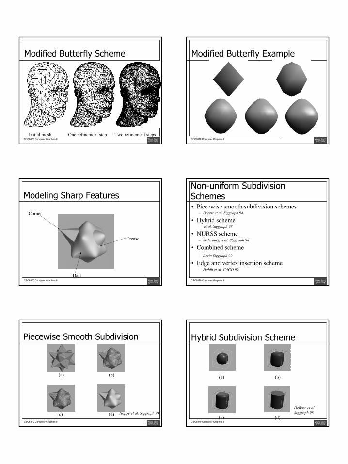
Modified Butterfly Example
CSC6870 Computer Graphics II
Modeling Sharp Features
Corner
Crease
DartCSC6870 Computer Graphics II
Non-uniform Subdivision Schemes• Piecewise smooth subdivision schemes
– Hoppe et al. Siggraph 94
• Hybrid scheme– et al. Siggraph 98
• NURSS scheme – Sederburg et al. Siggraph 98
• Combined scheme – Levin Siggraph 99
• Edge and vertex insertion scheme– Habib et al. CAGD 99
CSC6870 Computer Graphics II
Piecewise Smooth Subdivision
(a)
(d)(c)
(b)
Hoppe et al. Siggraph 94
CSC6870 Computer Graphics II
Hybrid Subdivision Scheme
(a)
(c) (d)
(b)
DeRose et al. Siggraph 98

8
CSC6870 Computer Graphics II
Hierarchical Editing
Zorin et al. Siggraph 97CSC6870 Computer Graphics II
Surface Reconstruction
Hoppe et al. Siggraph 94
CSC6870 Computer Graphics II
“Geri’s Game”
DeRose et al. Siggraph 98CSC6870 Computer Graphics II
Subdivision Splines• We treat subdivision as a novel method to produce spline-like models in the
limit• Key components for spline models
– Control points, basis functions over their parametric domain, parameterization, piecewise decomposition
• Parameterization is done naturally via subdivision• The initial control mesh serves as the parametric domain• Basis functions are available for regular settings as well as irregular settings• Control points for one patch are in the vicinity of its parametric domain from its
initial control vertices• Subdivision-based spline formulation is fundamental for physics-based
geometric modeling and design, finite element analysis, simulation, and the entire CAD/CAM processes
CSC6870 Computer Graphics II
Chaikin Curve Example
CSC6870 Computer Graphics II
Interpolation Curve Example

9
CSC6870 Computer Graphics II
Parameterization
CSC6870 Computer Graphics II
Butterfly Surface Example
CSC6870 Computer Graphics II
Control Vertices for Butterfly Surface
CSC6870 Computer Graphics II
Control Vertices for Surface Patches
CSC6870 Computer Graphics II
Butterfly Patches
CSC6870 Computer Graphics II
Butterfly Basis Function

10
CSC6870 Computer Graphics II
Catmull-Clark Surface Example
CSC6870 Computer Graphics II
Catmull-Clark Patches
CSC6870 Computer Graphics II
Catmull-Clark Basis Function
CSC6870 Computer Graphics II
Simple Sculpting Examplesoriginal object deformation cutting
extrusion fixed regions
CSC6870 Computer Graphics II
Chair Example --- Finite Element Simulation
Initial control lattice
Finite element structure after a few
subdivisions
Deformed object
Photo-realistic rendering
CSC6870 Computer Graphics II
Sculpting Toolscarving extrusion detail editing
joining sharp features deformation

11
CSC6870 Computer Graphics II
Sculpting Toolsinflation curve-based design
material mapping physical window
deflation
material probing
CSC6870 Computer Graphics II
Sculpting Toolspushing curve-based join
curve-based cutting multi-face extrusion
sweeping
feature deformation
CSC6870 Computer Graphics II
Interactive Sculpting
CSC6870 Computer Graphics II
More Examples
CSC6870 Computer Graphics II
Volume Editing and Visualization
compressiveforces
displacement mapping
original lattice
original volume
deformed lattice
deformed volumeCSC6870 Computer Graphics II
Sculpted CAD Models

12
CSC6870 Computer Graphics II
Subdivision Solids
CSC6870 Computer Graphics II
Scenes and Sculptures


![[XLS] · Web view5/3/2011 5/3/2011 1 10 6870 2 10 3570 3 10 6880 4 10 6870 5 10 9170 6 10 6890 7 10 8090 8 10 6870 9 10 580 10 10 1590 11 10 7860 12 10 7390 13 10 8290 14 10 2870 15](https://img.pdfslide.us/doc/110x75/5abcd5b87f8b9ab1118eac5d/xls-view532011-532011-1-10-6870-2-10-3570-3-10-6880-4-10-6870-5-10-9170-6.jpg)


![Just Arrived! [£ñB*h] 1 Tel:03-6870-2004 Fax:03-6870-2024](https://img.pdfslide.us/doc/110x75/622d6c125f637804fe3b46ab/just-arrived-bh-1-tel03-6870-2004-fax03-6870-2024-.jpg)