Embed Size (px)
Citation preview
42188A-MCU-11/2013
USER GUIDE
REB233-XPRO User Guide
Introduction
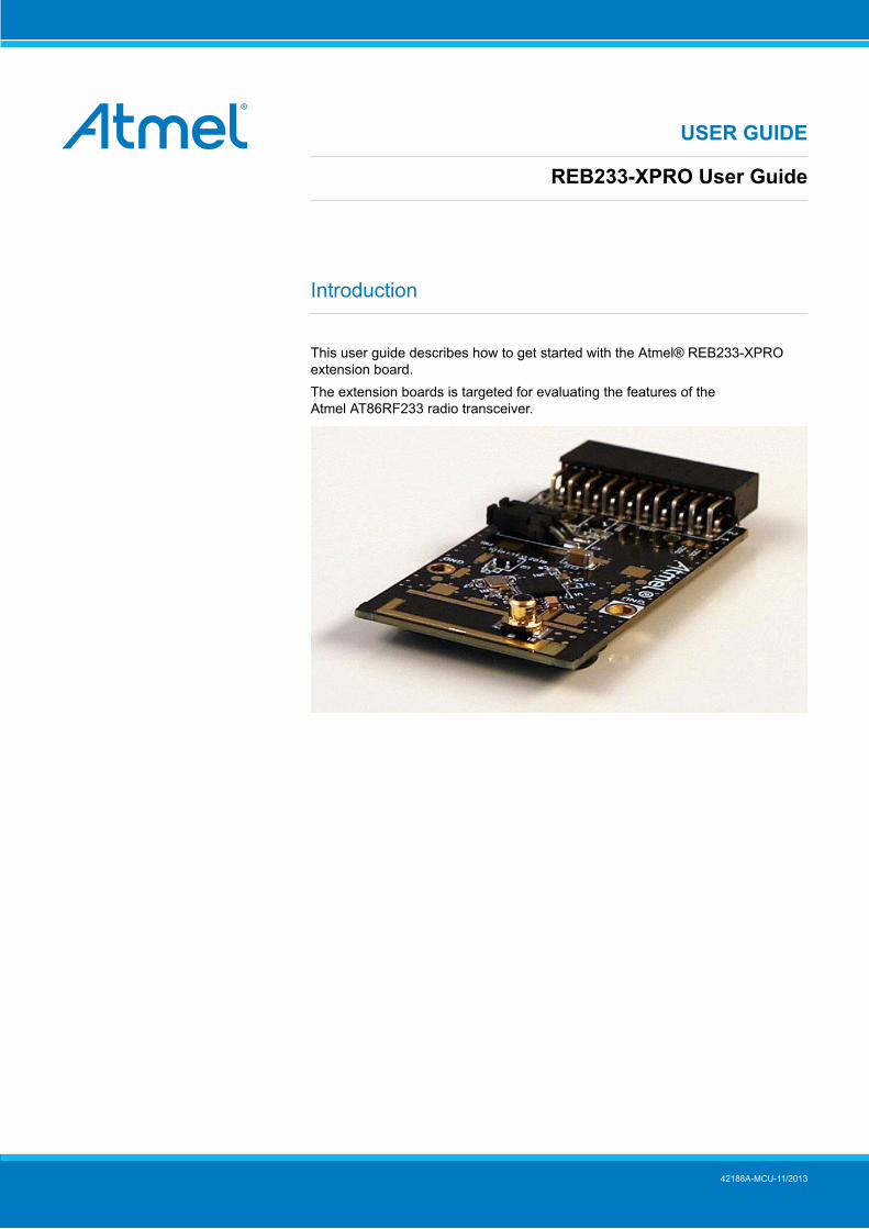
This user guide describes how to get started with the Atmel® REB233-XPROextension board.The extension boards is targeted for evaluating the features of theAtmel AT86RF233 radio transceiver.
REB233-XPRO User Guide [USER GUIDE]42188A-MCU-11/2013
2
Table of Contents
Introduction .................................................................................... 1
1. Getting Started ........................................................................ 31.1. Features .............................................................................. 31.2. Design Documentation and Related Links .................................. 31.3. Board Assembly .................................................................... 3
1.3.1. Connect to a Xplained Pro Board ................................. 31.3.2. In Customer Development Assembly ............................. 3
2. Performance Analyzer ............................................................. 42.1. Introduction .......................................................................... 42.2. Program Installation ............................................................... 42.3. Program Use ........................................................................ 72.4. Typical Wireless Nodes .......................................................... 7
3. Xplained Pro ............................................................................ 93.1. Hardware Identification System ................................................ 93.2. Standard Headers and Connectors ........................................... 9
3.2.1. Xplained Pro Standard Extension Header ...................... 9
4. Hardware User Guide ........................................................... 114.1. Board Overview .................................................................. 114.2. Headers and Connectors ...................................................... 11
4.2.1. J100 Xplained Pro Extension Connector ...................... 114.2.2. Current Monitoring (X3) ............................................ 12
4.3. U2 Serial EEPROM ............................................................. 12
5. Persistence Memory ............................................................. 13
6. Agency Certifications ............................................................ 146.1. United State (FCC) .............................................................. 146.2. European Union (ETSI) ........................................................ 146.3. Canada (IC) ....................................................................... 156.4. Using Limited Modular Certified Products ................................. 15
7. Document revision history ..................................................... 17
REB233-XPRO User Guide [USER GUIDE]42188A-MCU-11/2013
3
1. Getting Started
1.1 FeaturesThe REB233 extension is a template design for the AT86RF233 with a PCB antenna.
1.2 Design Documentation and Related LinksThe most relevant documents and software for the extension board1.
1.3 Board AssemblyThe extension board can be used to provide wireless communication to a Xplained PRO board or to providewireless communication to your own prototype for SW development and HW verification.
1.3.1 Connect to a Xplained Pro BoardThe Extension board can be connected to any Xplained PRO main board using the extension header.
1.3.2 In Customer Development AssemblyThe Extension board can be wired into the customer prototype assembly by using the on-board connectors, allrelevant signals are available.
1 http://www.atmel.com/tools/reb233-xpro.aspx
REB233-XPRO User Guide [USER GUIDE]42188A-MCU-11/2013
4
2. Performance Analyzer
2.1 IntroductionThe Performance Analyzer FW together with the GUI in Atmel Studio Wireless Composer Extension provides anumber of basic functional RF tests.
A quick start guide and general help is provided in Wireless Composer once started.
2.2 Program InstallationHow to install necessary SW.
1. Install Atmel Studio1.
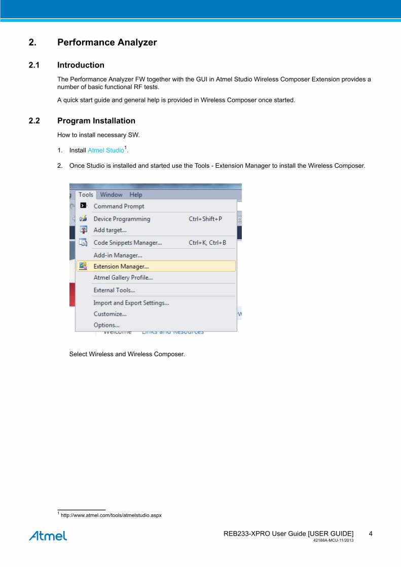
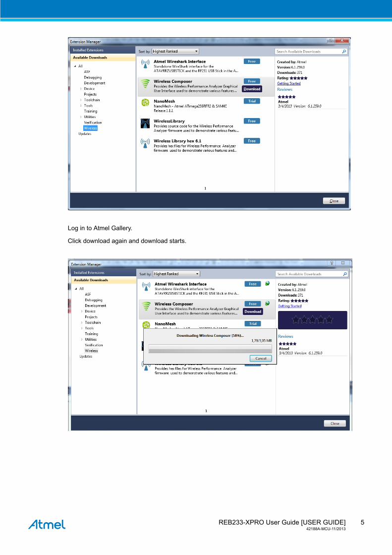
2. Once Studio is installed and started use the Tools - Extension Manager to install the Wireless Composer.
Select Wireless and Wireless Composer.
1 http://www.atmel.com/tools/atmelstudio.aspx
REB233-XPRO User Guide [USER GUIDE]42188A-MCU-11/2013
5
Log in to Atmel Gallery.
Click download again and download starts.
REB233-XPRO User Guide [USER GUIDE]42188A-MCU-11/2013
6
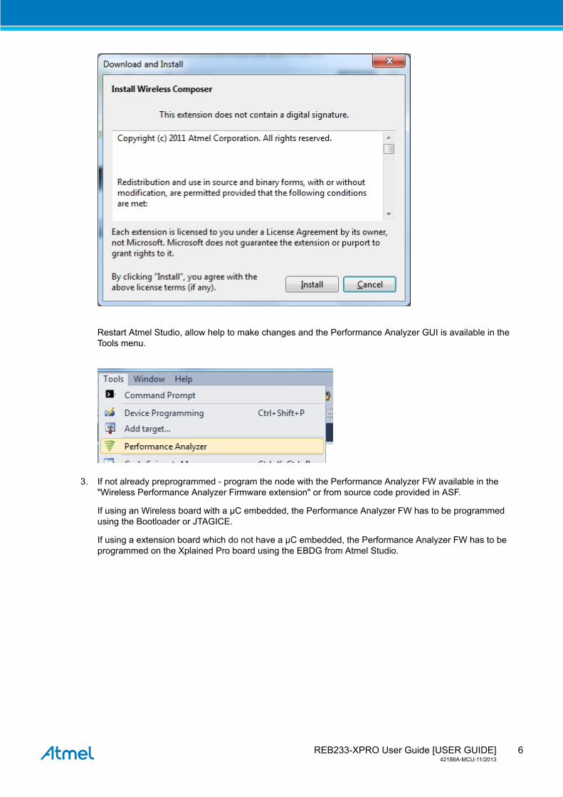
Restart Atmel Studio, allow help to make changes and the Performance Analyzer GUI is available in theTools menu.
3. If not already preprogrammed - program the node with the Performance Analyzer FW available in the"Wireless Performance Analyzer Firmware extension" or from source code provided in ASF.
If using an Wireless board with a μC embedded, the Performance Analyzer FW has to be programmedusing the Bootloader or JTAGICE.
If using a extension board which do not have a μC embedded, the Performance Analyzer FW has to beprogrammed on the Xplained Pro board using the EBDG from Atmel Studio.
REB233-XPRO User Guide [USER GUIDE]42188A-MCU-11/2013
7
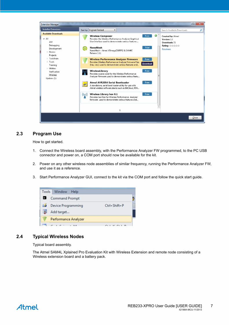
2.3 Program UseHow to get started.
1. Connect the Wireless board assembly, with the Performance Analyzer FW programmed, to the PC USBconnector and power on, a COM port should now be available for the kit.
2. Power on any other wireless node assemblies of similar frequency, running the Performance Analyzer FW,and use it as a reference.
3. Start Performance Analyzer GUI, connect to the kit via the COM port and follow the quick start guide.
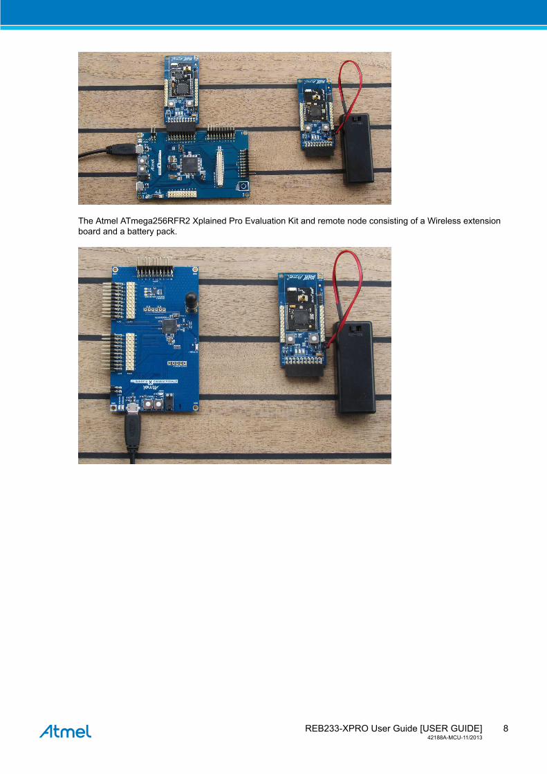
2.4 Typical Wireless NodesTypical board assembly.
The Atmel SAM4L Xplained Pro Evaluation Kit with Wireless Extension and remote node consisting of aWireless extension board and a battery pack.
REB233-XPRO User Guide [USER GUIDE]42188A-MCU-11/2013
8
The Atmel ATmega256RFR2 Xplained Pro Evaluation Kit and remote node consisting of a Wireless extensionboard and a battery pack.
REB233-XPRO User Guide [USER GUIDE]42188A-MCU-11/2013
9
3. Xplained ProXplained Pro is an evaluation platform that provides the full Atmel microcontroller experience. The platformconsists of a series of Microcontroller (MCU) boards and extension boards that are integrated with AtmelStudio, have Atmel Software Framework (ASF) drivers and demo code, support data streaming and more.Xplained Pro MCU boards support a wide range of Xplained Pro extension boards that are connected througha set of standardized headers and connectors. Each extension board has an identification (ID) chip to uniquelyidentify which boards are mounted on a Xplained Pro MCU board. This information is used to present relevantuser guides, application notes, datasheets and example code through Atmel Studio. Available Xplained ProMCU and extension boards can be purchased in the Atmel Web Store1.
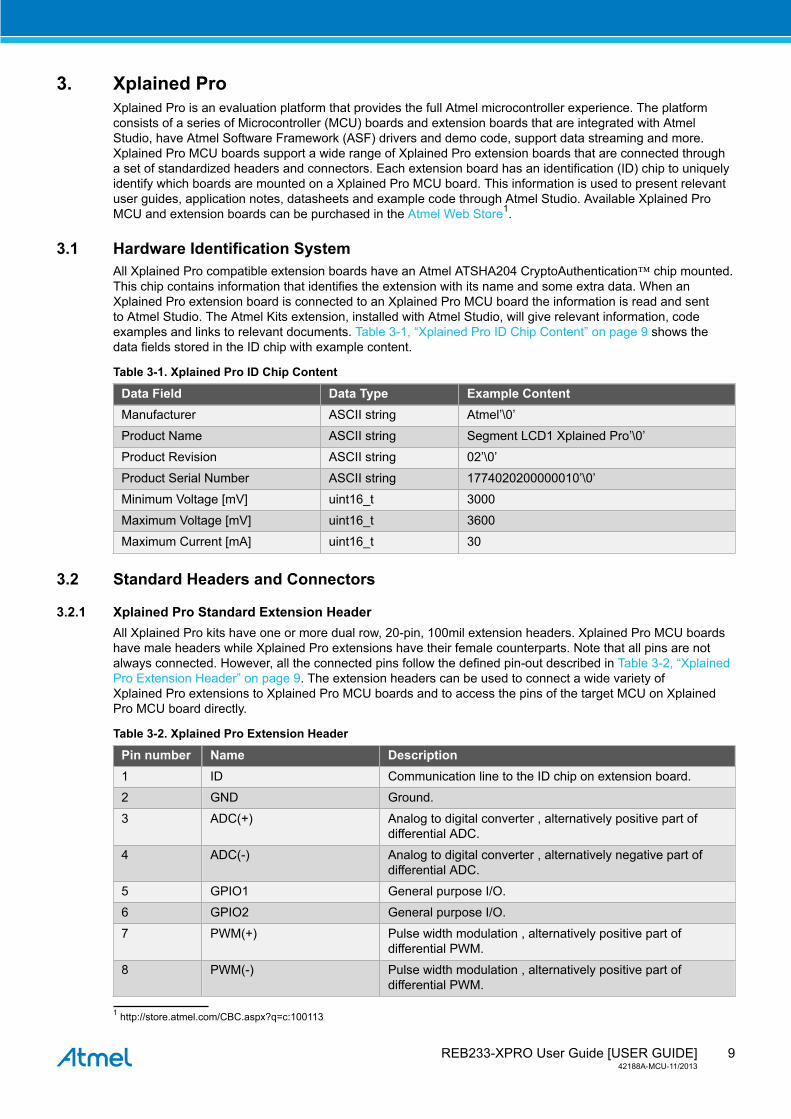
3.1 Hardware Identification SystemAll Xplained Pro compatible extension boards have an Atmel ATSHA204 CryptoAuthentication™ chip mounted.This chip contains information that identifies the extension with its name and some extra data. When anXplained Pro extension board is connected to an Xplained Pro MCU board the information is read and sentto Atmel Studio. The Atmel Kits extension, installed with Atmel Studio, will give relevant information, codeexamples and links to relevant documents. Table 3-1, “Xplained Pro ID Chip Content” on page 9 shows thedata fields stored in the ID chip with example content.
Table 3-1. Xplained Pro ID Chip Content
Data Field Data Type Example ContentManufacturer ASCII string Atmel’\0’
Product Name ASCII string Segment LCD1 Xplained Pro’\0’
Product Revision ASCII string 02’\0’
Product Serial Number ASCII string 1774020200000010’\0’
Minimum Voltage [mV] uint16_t 3000
Maximum Voltage [mV] uint16_t 3600
Maximum Current [mA] uint16_t 30
3.2 Standard Headers and Connectors
3.2.1 Xplained Pro Standard Extension HeaderAll Xplained Pro kits have one or more dual row, 20-pin, 100mil extension headers. Xplained Pro MCU boardshave male headers while Xplained Pro extensions have their female counterparts. Note that all pins are notalways connected. However, all the connected pins follow the defined pin-out described in Table 3-2, “XplainedPro Extension Header” on page 9. The extension headers can be used to connect a wide variety ofXplained Pro extensions to Xplained Pro MCU boards and to access the pins of the target MCU on XplainedPro MCU board directly.
Table 3-2. Xplained Pro Extension Header
Pin number Name Description1 ID Communication line to the ID chip on extension board.
2 GND Ground.
3 ADC(+) Analog to digital converter , alternatively positive part ofdifferential ADC.
4 ADC(-) Analog to digital converter , alternatively negative part ofdifferential ADC.
5 GPIO1 General purpose I/O.
6 GPIO2 General purpose I/O.
7 PWM(+) Pulse width modulation , alternatively positive part ofdifferential PWM.
8 PWM(-) Pulse width modulation , alternatively positive part ofdifferential PWM.
1 http://store.atmel.com/CBC.aspx?q=c:100113
REB233-XPRO User Guide [USER GUIDE]42188A-MCU-11/2013
10
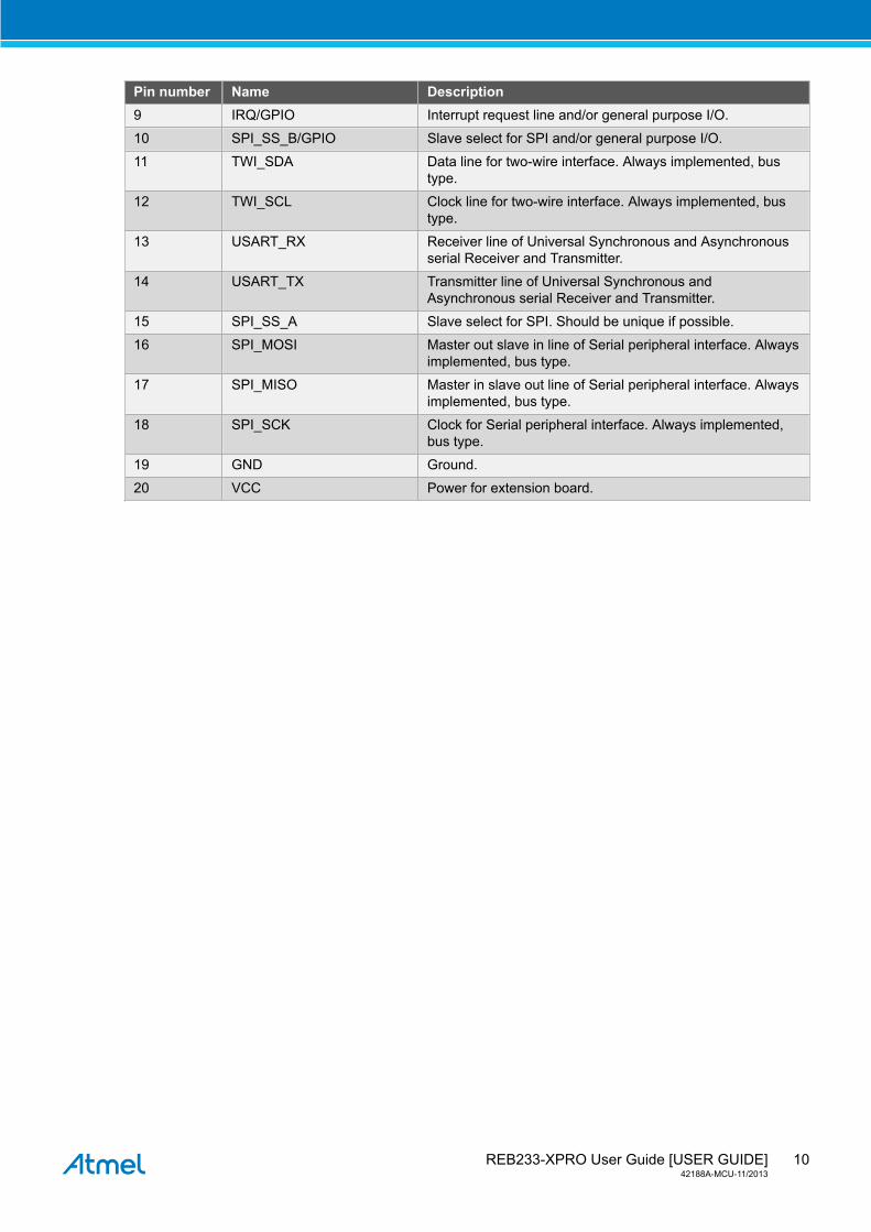
Pin number Name Description9 IRQ/GPIO Interrupt request line and/or general purpose I/O.
10 SPI_SS_B/GPIO Slave select for SPI and/or general purpose I/O.
11 TWI_SDA Data line for two-wire interface. Always implemented, bustype.
12 TWI_SCL Clock line for two-wire interface. Always implemented, bustype.
13 USART_RX Receiver line of Universal Synchronous and Asynchronousserial Receiver and Transmitter.
14 USART_TX Transmitter line of Universal Synchronous andAsynchronous serial Receiver and Transmitter.
15 SPI_SS_A Slave select for SPI. Should be unique if possible.
16 SPI_MOSI Master out slave in line of Serial peripheral interface. Alwaysimplemented, bus type.
17 SPI_MISO Master in slave out line of Serial peripheral interface. Alwaysimplemented, bus type.
18 SPI_SCK Clock for Serial peripheral interface. Always implemented,bus type.
19 GND Ground.
20 VCC Power for extension board.
REB233-XPRO User Guide [USER GUIDE]42188A-MCU-11/2013
11
4. Hardware User Guide
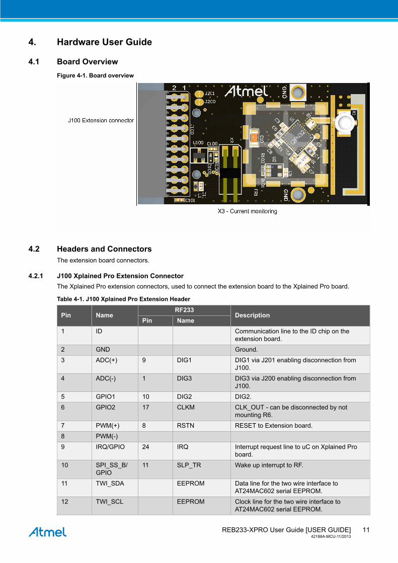
4.1 Board OverviewFigure 4-1. Board overview
4.2 Headers and ConnectorsThe extension board connectors.
4.2.1 J100 Xplained Pro Extension ConnectorThe Xplained Pro extension connectors, used to connect the extension board to the Xplained Pro board.
Table 4-1. J100 Xplained Pro Extension Header
RF233Pin Name
Pin NameDescription
1 ID Communication line to the ID chip on theextension board.
2 GND Ground.
3 ADC(+) 9 DIG1 DIG1 via J201 enabling disconnection fromJ100.
4 ADC(-) 1 DIG3 DIG3 via J200 enabling disconnection fromJ100.
5 GPIO1 10 DIG2 DIG2.
6 GPIO2 17 CLKM CLK_OUT - can be disconnected by notmounting R6.
7 PWM(+) 8 RSTN RESET to Extension board.
8 PWM(-)
9 IRQ/GPIO 24 IRQ Interrupt request line to uC on Xplained Proboard.
10 SPI_SS_B/GPIO
11 SLP_TR Wake up interrupt to RF.
11 TWI_SDA EEPROM Data line for the two wire interface toAT24MAC602 serial EEPROM.
12 TWI_SCL EEPROM Clock line for the two wire interface toAT24MAC602 serial EEPROM.
REB233-XPRO User Guide [USER GUIDE]42188A-MCU-11/2013
12
RF233Pin Name
Pin NameDescription
13 USART_RX
14 USART_TX
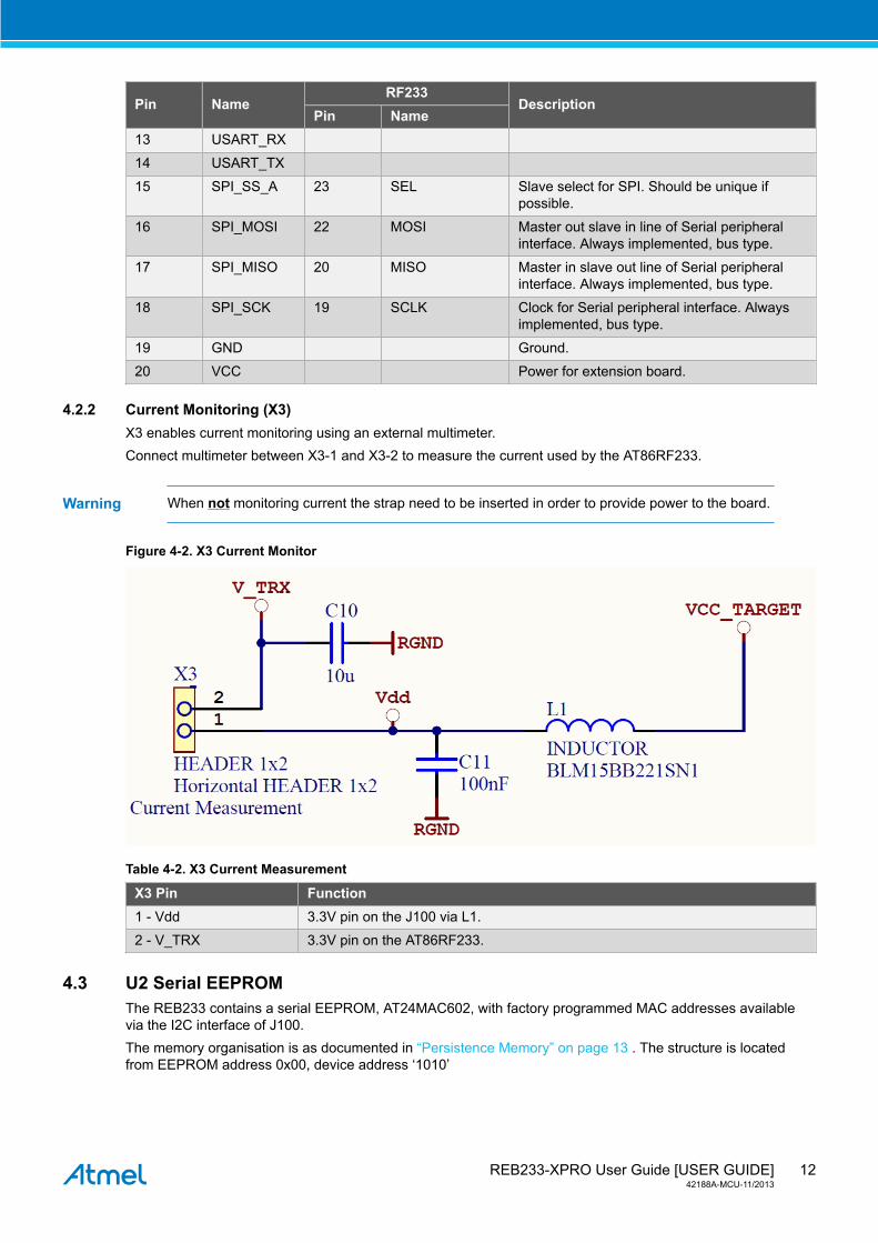
15 SPI_SS_A 23 SEL Slave select for SPI. Should be unique ifpossible.
16 SPI_MOSI 22 MOSI Master out slave in line of Serial peripheralinterface. Always implemented, bus type.
17 SPI_MISO 20 MISO Master in slave out line of Serial peripheralinterface. Always implemented, bus type.
18 SPI_SCK 19 SCLK Clock for Serial peripheral interface. Alwaysimplemented, bus type.
19 GND Ground.
20 VCC Power for extension board.
4.2.2 Current Monitoring (X3)X3 enables current monitoring using an external multimeter.Connect multimeter between X3-1 and X3-2 to measure the current used by the AT86RF233.
Warning When not monitoring current the strap need to be inserted in order to provide power to the board.
Figure 4-2. X3 Current Monitor
Table 4-2. X3 Current Measurement
X3 Pin Function1 - Vdd 3.3V pin on the J100 via L1.
2 - V_TRX 3.3V pin on the AT86RF233.
4.3 U2 Serial EEPROMThe REB233 contains a serial EEPROM, AT24MAC602, with factory programmed MAC addresses availablevia the I2C interface of J100.The memory organisation is as documented in “Persistence Memory” on page 13 . The structure is locatedfrom EEPROM address 0x00, device address ‘1010’
REB233-XPRO User Guide [USER GUIDE]42188A-MCU-11/2013
13
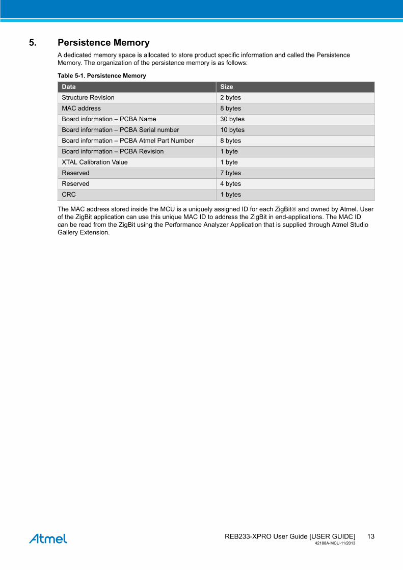
5. Persistence MemoryA dedicated memory space is allocated to store product specific information and called the PersistenceMemory. The organization of the persistence memory is as follows:
Table 5-1. Persistence Memory
Data SizeStructure Revision 2 bytes
MAC address 8 bytes
Board information – PCBA Name 30 bytes
Board information – PCBA Serial number 10 bytes
Board information – PCBA Atmel Part Number 8 bytes
Board information – PCBA Revision 1 byte
XTAL Calibration Value 1 byte
Reserved 7 bytes
Reserved 4 bytes
CRC 1 bytes
The MAC address stored inside the MCU is a uniquely assigned ID for each ZigBit® and owned by Atmel. Userof the ZigBit application can use this unique MAC ID to address the ZigBit in end-applications. The MAC IDcan be read from the ZigBit using the Performance Analyzer Application that is supplied through Atmel StudioGallery Extension.

REB233-XPRO User Guide [USER GUIDE]42188A-MCU-11/2013
14
6. Agency Certifications
6.1 United State (FCC)This equipment complies with Part 15 of the FCC rules and regulations. To fulfill FCC Certificationrequirements, an OEM manufacturer must comply with the following regulations:
1. The ATREB233-XPRO modular transmitter must be labelled with its own FCC ID number, and, if the FCCID is not visible when the module is installed inside another device, then the outside of the device intowhich the module is installed must also display a label referring to the enclosed module. This exterior labelcan use wording such as the following:
Important Contains FCC ID : VW4A091887. This equipment complies with Part 15 of the FCC Rules.Operation is subject to the following two conditions:
(1) this device may not cause harmful interference, and
(2) this device must accept any interference received, including interference that may causeundesired operation (FCC 15.19)
The internal antenna used for this mobile transmitter must provide a separation distance of at least 20 cmfrom all persons and must not be co-located or operating in conjunction with any other antenna or transmitter.Installers must be provided with antenna installation instructions and transmitter operating conditions forsatisfying RF exposure compliance. This device is approved as a mobile device with respect to RF exposurecompliance, and may only be marketed to OEM installers. Use in portable exposure conditions (FCC 2.1093)requires separate equipment authorization.
Important Modifications not expressly approved by this company could void the user's authority to operatethis equipment (FCC section 15.21).
Important This equipment has been tested and found to comply with the limits for a Class A digital device,pursuant to Part 15 of the FCC Rules. These limits are designed to provide reasonable protectionagainst harmful interference when the equipment is operated in a commercial environment.This equipment generates, uses, and can radiate radio frequency energy and, if not installedand used in accordance with the instruction manual, may cause harmful interference to radiocommunications. Operation of this equipment in a residential area is likely to cause harmfulinterference in which case the user will be required to correct the interference at his own expense(FCC section 15.105).
ATREB233-XPRO is limited modular approved and required separate approval for this module when used onan application board.
Cet appareil est conforme à la section 15 des réglementations de la FCC. Le fonctionnement de l’appareil estsujetaux deux conditions suivantes:
(1) cet appareil ne doit pas provoquer d’interférences néfastes, et
(2) cet appareil doit tolérer les interférences reçues, y compris celles qui risquent de provoquer unfonctionnement indésirable
6.2 European Union (ETSI)The ATREB233-XPRO Module has been certified for use in European Union countries. If these modules areincorporated into a product, the manufacturer must ensure compliance of the final product to the Europeanharmonized EMC and low voltage/safety standards. A Declaration of Conformity must be issued for each ofthese standards and kept on file as described in Annex II of the R&TTE Directive.
Furthermore, the manufacturer must maintain a copy of the modules' documentation and ensure the finalproduct does not exceed the specified power ratings, antenna specifications, and/or installation requirementsas specified in the user manual. If any of these specifications are exceeded in the final product, a submissionmust be made to a notified body for compliance testing to all required standards.
REB233-XPRO User Guide [USER GUIDE]42188A-MCU-11/2013
15
Important The 'CE' marking must be affixed to a visible location on the OEM product. The CE mark shallconsist of the initials "CE" taking the following form:
The CE marking must have a height of at least 5mm except where this is not possible on accountof the nature of the apparatus. The CE marking must be affixed visibly, legibly, and indelibly. Moredetailed information about CE marking requirements you can find at "DIRECTIVE 1999/5/EC OFTHE EUROPEAN PARLIAMENT AND OF THE COUNCIL" on 9 March 1999 at section 12.
6.3 Canada (IC)The ATREB233-XPRO Module complies with Industry Canada specifications RSS-210 and RSS – GenIC.
ID for ATREB233-XPRO is 11019A-091887
ATREB233-XPRO is limited modular approved and required separate approval for this module when used onan application board.
User manuals for licence-exempt radio apparatus shall contain the following or equivalent notice in aconspicuous location in the user manual or alternatively on the device or both.
This device complies with Industry Canada licence-exempt RSS standard(s). Operation is subject to thefollowing two conditions:
(1 )this device may not cause interference, and
(2) this device must accept any interference, including interference that may cause undesired operation of thedevice.
Le présent appareil est conforme aux CNR d'Industrie Canada applicables aux appareils radioexempts delicence. L'exploitation est autorisée aux deux conditions suivantes:
(1)l'appareil ne doit pas produire de brouillage, et
(2)l'utilisateur de l'appareil doit accepter tout brouillage radioélectrique subi, même si le brouillage estsusceptible d'en compromettre le fonctionnement.
Under Industry Canada regulations, this radio transmitter may only operate using an antenna of a typeand maximum (or lesser) gain approved for the transmitter by Industry Canada. To reduce potential radiointerference to other users, the antenna type and its gain should be so chosen that the equivalent isotropicallyradiated power (e.i.r.p.) is not more than that necessary for successful communication
Conformément à la réglementation d'Industrie Canada, le présent émetteur radio peut fonctionner avec uneantenne d'un type et d'un gain maximal (ou inférieur) approuvé pour l'émetteur par Industrie Canada. Dansle but de réduire les risques de brouillage radioélectrique à l'intention des autres utilisateurs, il faut choisir letype d'antenne et son gain de sorte que la puissance isotrope rayonnée équivalente (p.i.r.e.) ne dépasse pasl'intensité nécessaire à l'établissement d'une communication satisfaisante.
6.4 Using Limited Modular Certified ProductsThe ATREB233-XPRO Module is certified under part 15 of FCC rules. The Modular certification category of thismodule is “Limited Modular”. The End product using these modules hence has to undergo compliance testingand receive a new FCC ID for the final product carrying these modules. Certification of the final product liessolely with the type of design of the final product.
REB233-XPRO User Guide [USER GUIDE]42188A-MCU-11/2013
16
Warning The Original Equipment Manufacturer (OEM) must ensure that the OEM modular transmitter mustbe labeled with its own FCC ID number. This includes a clearly visible label on the outside of thefinal product enclosure that displays the contents shown below. If the FCC ID is not visible whenthe equipment is installed inside another device, then the outside of the device into which theequipment is installed must also display a label referring to the enclosed equipment.
Important This equipment complies with Part 15 of the FCC Rules. Operation is subject to the followingtwo conditions: (1) this device may not cause harmful interference, and (2) this device mustaccept any interference received, including interference that may cause undesired operation(FCC 15.19). The internal / external antenna(s) used for this mobile transmitter must providea separation distance of at least 20cm from all persons and must not be co-located oroperating in conjunction with any other antenna or transmitter. Installers must be providedwith antenna installation instructions and transmitter operating conditions for satisfying RFexposure compliance. This device is approved as a mobile device with respect to RF expo- surecompliance, and may only be marketed to OEM installers. Use in portable exposure conditions(FCC 2.1093) requires separate equipment authorization.
Important Modifications not expressly approved by this company could void the user's authority to operatethis equipment (FCC section 15.21).
Important This equipment has been tested and found to comply with the limits for a Class A digital device,pursuant to Part 15 of the FCC Rules. These limits are designed to provide reasonable protectionagainst harmful interference when the equipment is operated in a commercial environment.This equipment generates, uses, and can radiate radio frequency energy and, if not installedand used in accordance with the instruction manual, may cause harmful interference to radiocommunications. Operation of this equipment in a residential area is likely to cause harmfulinterference in which case the user will be required to correct the interference at his own expense(FCC section 15.105).
REB233-XPRO User Guide [USER GUIDE]42188A-MCU-11/2013
17
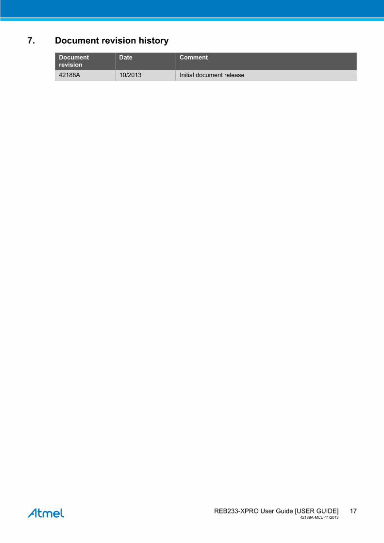
7. Document revision history
Documentrevision
Date Comment
42188A 10/2013 Initial document release

Atmel Corporation 1600 Technology Drive, San Jose, CA 95110 USA T: (+1)(408) 441.0311 F: (+1)(408) 436.4200 | www.atmel.com
© 2013 Atmel Corporation. All rights reserved. / Rev.: 42188A-MCU-11/2013
Atmel®, Atmel logo and combinations thereof, Enabling Unlimited Possibilities®, ZigBit®, and others are registered trademarks or trademarks of AtmelCorporation or its subsidiaries. Other terms and product names may be trademarks of others.
Disclaimer: The information in this document is provided in connection with Atmel products. No license, express or implied, by estoppel or otherwise, to any intellectual property right is grantedby this document or in connection with the sale of Atmel products. EXCEPT AS SET FORTH IN THE ATMEL TERMS AND CONDITIONS OF SALES LOCATED ON THE ATMEL WEBSITE,ATMEL ASSUMES NO LIABILITY WHATSOEVER AND DISCLAIMS ANY EXPRESS, IMPLIED OR STATUTORY WARRANTY RELATING TO ITS PRODUCTS INCLUDING, BUT NOTLIMITED TO, THE IMPLIED WARRANTY OF MERCHANTABILITY, FITNESS FOR A PARTICULAR PURPOSE, OR NON-INFRINGEMENT. IN NO EVENT SHALL ATMEL BE LIABLE FORANY DIRECT, INDIRECT, CONSEQUENTIAL, PUNITIVE, SPECIAL OR INCIDENTAL DAMAGES (INCLUDING, WITHOUT LIMITATION, DAMAGES FOR LOSS AND PROFITS, BUSINESSINTERRUPTION, OR LOSS OF INFORMATION) ARISING OUT OF THE USE OR INABILITY TO USE THIS DOCUMENT, EVEN IF ATMEL HAS BEEN ADVISED OF THE POSSIBILITY OFSUCH DAMAGES. Atmel makes no representations or warranties with respect to the accuracy or completeness of the contents of this document and reserves the right to make changes tospecifications and products descriptions at any time without notice. Atmel does not make any commitment to update the information contained herein. Unless specifically provided otherwise,Atmel products are not suitable for, and shall not be used in, automotive applications. Atmel products are not intended, authorized, or warranted for use as components in applications intendedto support or sustain life.


![SAM D21 XPRO USB Host MSC Bootloader · SAM D21 XPRO USB Host MSC Bootloader [TRAINING MANUAL] Atmel-42352A-SAM-D21-XPRO-USB-Host-MSC-Bootloader_Training-Manual_022015 4 1 Training](https://img.pdfslide.us/doc/110x75/5f0556927e708231d41278b3/sam-d21-xpro-usb-host-msc-bootloader-sam-d21-xpro-usb-host-msc-bootloader-training.jpg)


![REB215-XPRO Extension Board (USER GUIDE) · PDF fileREB215-XPRO Extension Board [USER GUIDE] 42398A-MCU-03/2015 6 Restart Atmel Studio, allow help to make changes and the Performance](https://img.pdfslide.us/doc/110x75/5aa6da3d7f8b9a424f8b90a3/reb215-xpro-extension-board-user-guide-extension-board-user-guide-42398a-mcu-032015.jpg)


![User Guide...User. {{]}]} {}]}](https://img.pdfslide.us/doc/110x75/60918ca14327954d24291644/-user-guide-user-.jpg)

![XPRO INDIA LIMITED AR 2011-12.pdf · XPRO INDIA LIMITED : ANNUAL REPORT 2011/12 [ 1 ] Board of Directors Sri Sidharth Birla Chairman](https://img.pdfslide.us/doc/110x75/5a729c837f8b9a93538dddcd/xpro-india-limitedwwwxproindiacomdataxpro-ar-2011-12pdfpdf.jpg)