Embed Size (px)
Citation preview
INTRODUCTION
Upon completing this topic, you should be able to:• Illustrate a basic elements of digital
computer system and their functions,• Depicts the three main units consist inside
microprocessor,• Differentiate the function of address, data
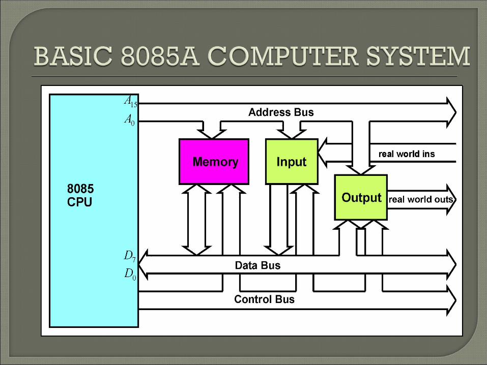
and control bus,• Draw and explain the basic 8085A computer
system.


The memory system of a computer is used to :• Store the programs the computer is required to
execute• Store the data that is to be processed by those
programs
Information is stored in memory in binary form. There are many memory locations in the
memory system of a digital computer. Each memory location can store n binary digits
(n-bits). N is usually an integer multiple of 8. Each memory location is given a unique
identifier, called its address.
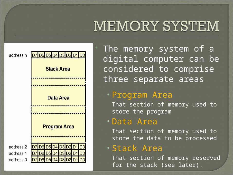
The memory system of a digital computer can be considered to comprise three separate areas
• Program AreaThat section of memory used to store the program
• Data AreaThat section of memory used to store the data to be processed
• Stack AreaThat section of memory reserved for the stack (see later).

Input / Output devices provide a communication interface between the digital computer and the outside world.
Examples of input devices are :• a keyboard• a mouse
Examples of output devices are:• a printer
• a visual display unit

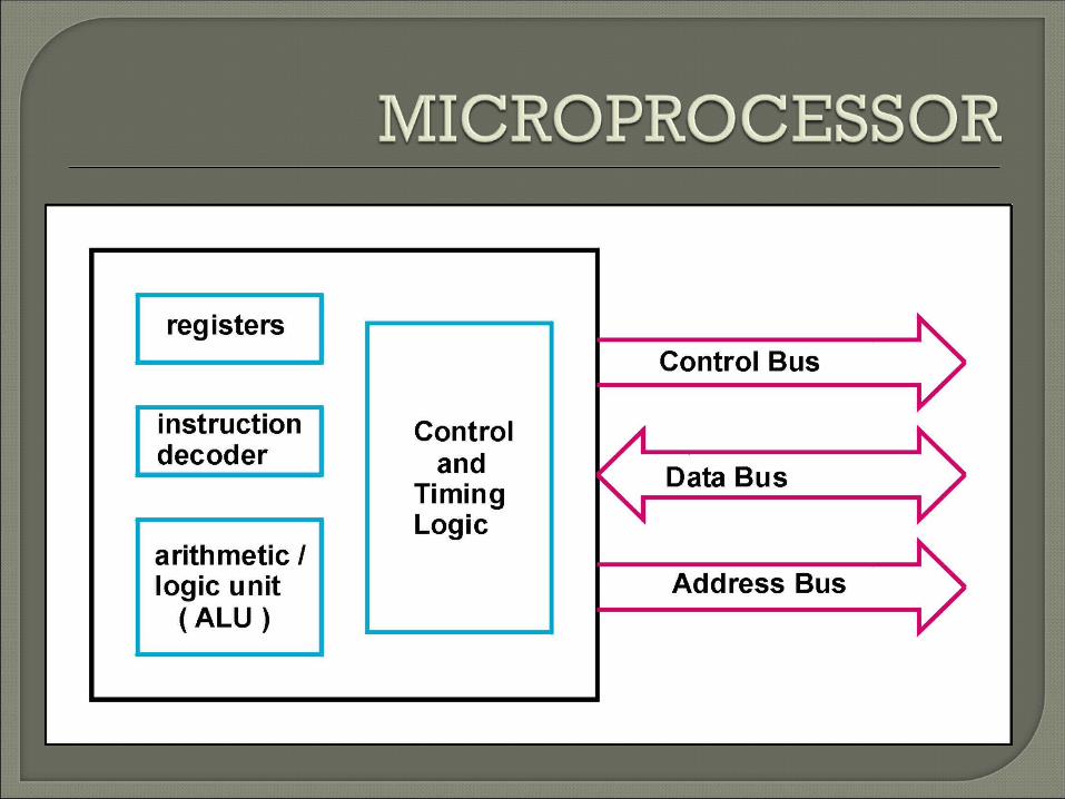
A microprocessor is a single, digital integrated circuit that performs the function of a central processing unit ( CPU ).
A microprocessor is a collection of digital circuits that:process binary dataprovide control and timing references
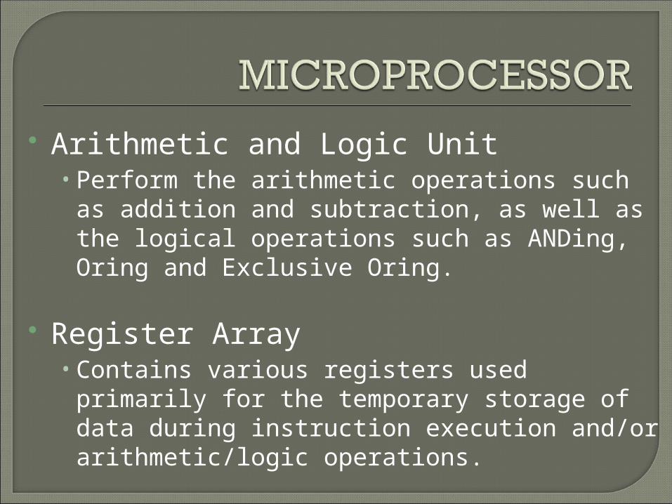
Arithmetic and Logic Unit• Perform the arithmetic operations such as
addition and subtraction, as well as the logical operations such as ANDing, Oring and Exclusive Oring.
Register Array • Contains various registers used primarily for the
temporary storage of data during instruction execution and/or arithmetic/logic operations.

Control and Timing Logic Unit• Provides the necessary timing and control
signals for all the operations in the microprocessor.
• This unit controls the flow of information between the microprocessor, memory and peripheral devices.
Instruction Decoder• Used to decodes the instructions it receives
from internal data bus
Buses are used to interconnect the sub-systems of a computer.
A bus is a multi-way set of electrical connections which share a common purpose.
Each bus line can carry one binary digit (Bit) Thus to convey 8-bits of information from one
sub-system of a computer to another, simultaneously, requires an 8-bit bus.
8-bits, collectively, is called a byte. Data buses of most computers are byte wide or an integer multiple of bytes wide.
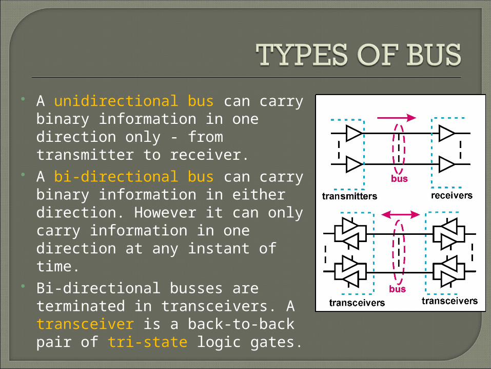
A unidirectional bus can carry binary information in one direction only - from transmitter to receiver.
A bi-directional bus can carry binary information in either direction. However it can only carry information in one direction at any instant of time.
Bi-directional busses are terminated in transceivers. A transceiver is a back-to-back pair of tri-state logic gates.
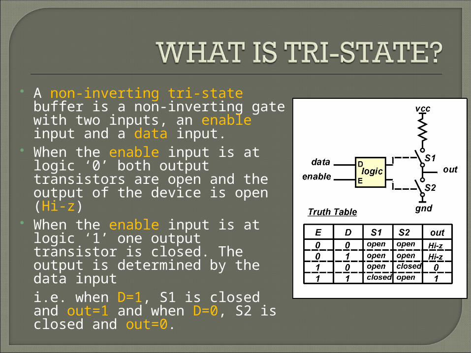
A non-inverting tri-state buffer is a non-inverting gate with two inputs, an enable input and a data input.
When the enable input is at logic ‘0’ both output transistors are open and the output of the device is open (Hi-z)
When the enable input is at logic ‘1’ one output transistor is closed. The output is determined by the data input i.e. when D=1, S1 is closed and out=1 and when D=0, S2 is closed and out=0.

System bus is a bus that is composed of three separate buses; Address Bus
Data Bus
Control Bus

The address bus is used by the CPU to specify which memory location ( or input/output device ) it wishes to access.
In simple systems the address bus is a unidirectional bus with the CPU as the transmitter and memory and I/O devices as receivers.
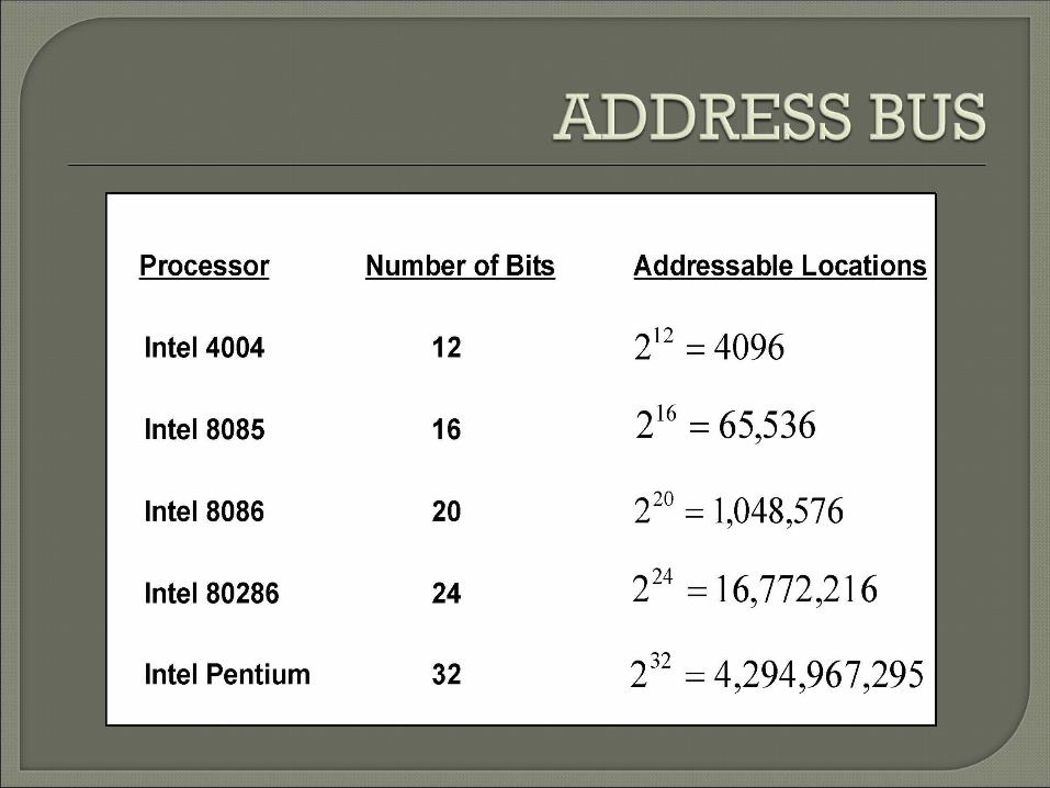
An address bus x-bits wide enables a CPU to uniquely identify any one of locations
2x


The Data Bus is the bus over which the binary data, stored at an addressed location, is transferred to/from the CPU.
The data bus is a bi-directional bus. Data can be transferred from the processor to
an addressed location - a write operation. Data can be transferred to the processor from
an addressed location - a read operation. Data bus widths correspond to the number of
binary digits stored at a location - usually an integer multiple of 8


The control bus is a unidirectional bus
Some control signals are processor outputs, thus enabling the processor to instruct peripheral devices to perform the particular type of operation it wishes to execute.
Some control signals are processor inputs, thus enabling peripheral devices to provide control information to the processor.
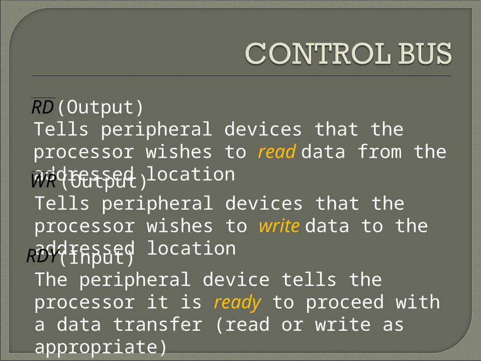
RD (Output)Tells peripheral devices that the processor wishes to read data from the addressed locationWR (Output)Tells peripheral devices that the processor wishes to write data to the addressed locationRDY (Input)The peripheral device tells the processor it is ready to proceed with a data transfer (read or write as appropriate)