Embed Size (px)
Citation preview

Featuring the
Burner
• Direct Vent Freestanding Stove
• Natural Gas or Propane
• Vent Horizontally or Vertically
• Standard Residential
• Mobile Home ApprovedTested and Listed by
OMNI-Test Laboratories, Inc.Beaverton, Oregon
Report # 028-S-55-5ANSI Z21.88
WARNING: If the information in these instructions is not followed exactly, a fire orexplosion may result causing property damage, personal injury or loss of life.
- Do not store or use gasoline or other flammable vapors and liquids in the vicinity of this orany other appliance.
WHAT TO DO IF YOU SMELL GAS• Do not try to light any appliance.• Do not touch any electrical switch; do not use any phone in your building.• Immediately call gas supplier from a neighbor's phone. Follow the gas supplier's
instructions.• If you cannot reach your gas supplier, call the fire department.
- Installation and service must be performed by a qualified installer, service agency or thegas supplier.
This appliance may be installed in an aftermarket permanently located, manufacturedhome (USA only) or mobile home, where not prohibited by local codes.
This appliance is only for use with the type of gas indicated on the rating plate. Thisappliance is not convertible for use with other gases unless a certified kit is used.
Sweet Dreams ManualInstaller: After installation give this manual to the home-owner
and explain operation of this heater.
Copyright 2005, T.I. $10.00 100-01155 4040903
4800 Harbour Pointe Blvd. SWMukilteo, WA 98275

2 Introduction
Travis Industries 100-01155 4040903
Introduction
We welcome you as a new owner of a Lopi Sweet Dreams stove. In purchasing a Sweet Dreams youhave joined the growing ranks of concerned individuals whose selection of an energy system reflectsboth a concern for the environment and aesthetics. The Sweet Dreams is one of the finest homeheaters the world over. This manual will explain the installation, operation, and maintenance of thisstove. Please familiarize yourself with the Owner's Manual before operating your heater and save themanual for future reference. Included are helpful hints and suggestions that will make the operationand maintenance of your new stove an easier and more enjoyable experience. We offer our continualsupport and guidance to help you achieve the maximum benefit and enjoyment from your heater.
Important InformationNo other Sweet Dreams Stove has the same serialnumber as yours. The serial number is on the listingplate chained to the gas control valve.
This serial number will be needed in case you requireservice of any type.
Model: Lopi Sweet Dreams Stove
Serial Number:
Purchase Date:
Purchased From:
Mail your Warranty CardToday, and Save Your Bill ofSa le .
To receive full warranty coverage,you will need to show evidence ofthe date you purchased yourheater. Do not mail your Bill ofSale to us.
We suggest that you attach yourBill of Sale to this page so that youwill have all the information youneed in one place should the needfor service or information occur.

Table of Contents 3
Travis Industries 100-01155 4040903
IntroductionIntroduction & Important Information................2
Safety PrecautionsSafety Precautions ......................................4
Features & SpecificationsFeatures ....................................................6
Installation Options......................................6
Heating Specifications..................................6
Dimensions.................................................6
InstallationInstallation Warning......................................7
Packing List................................................7
Additional Items Required for Installation..........7
Installation Overview....................................7
Installation Hints..........................................8
Stove Clearances ........................................8Mobile Home Requirements............................8
Heater Placement Requirements.....................9
Floor Protection Requirements........................9
Gas Line Installation.....................................10
Vent Requirements.......................................11
Altitude Considerations ............................11
Vent Clearances .....................................11
Part Numbers for 8” Vent...........................12
Vent Installation......................................12
Approved Vent Configurations........................13
Restrictor Position...................................13
Diffuser Plate .........................................13
Vertical Terminations ...............................14
Horizontal Terminations – LP (Propane) .......15
Horizontal Terminations – NG (Natural Gas) ..16
Horizontal Term. with 45° Elbow (NG or LP) ...17
Vent Termination Requirements ......................18
Finalizing the InstallationStove Top and Face Removal .........................19
Glass Frame Removal ...................................20
Log Installation............................................22
Purge Gas & Leak Test .................................24
Pilot Adjustment (if necessary) .......................24
Air Shutter Adjustment (if necessary)...............24
Check Flame...............................................25
Explain Operation to Home Owner ...................25
OperationBefore You Begin.........................................26
Location of Controls .....................................26
Starting The Pilot .........................................27
Starting the Stove for the First Time.................28
Turning the Stove On and Off .........................28
Adjusting the Flame Height.............................28
Adjusting the Blower Speed (optional) ..............29
Normal Operating Sounds..............................29
Normal Operating Odors................................29
MaintenanceMaintaining Your Stove’s Appearance..............30
Yearly Service Procedure..............................30
Troubleshooting Table...................................31
How this Stove Works...................................32
What Turns the Main Burners On and Off......32
What Prevents Gas Buildup.......................32
Wiring Diagram ............................................33
Replacement Parts List .................................33
Safety LabelSafety (Listing) Label....................................34
WarrantyWarranty ....................................................35
Optional EquipmentOptional Accessories ...................................36
LP Conversion Kit ........................................37
Blower .......................................................40
Leg Mounting Kit ..........................................43
Index Index.........................................................44
4 Safety Precautions
Travis Industries 100-01155 4040903
• IF YOU SMELL GAS:* Do not light any appliance
* Extinguish any open flame
* Do not touch any electrical switch or plug or unplug anything
* Open windows and vacate building
* Call gas supplier from neighbor's house, if not reached, call firedepartment
• This unit must be installed by a qualified installer to prevent thepossibility of an explosion. Your dealer will know the requirements inyour area and can inform you of those people considered qualified.The room heater should be inspected before use and at least annuallyby a qualified service person. More frequent cleaning may berequired due to excessive lint from carpeting, bedding material, etc.
• The instructions in this manual must be strictly adhered to. Do not use makeshiftmethods or compromise in the installation. Improper installation will void the warrantyand safety listing.
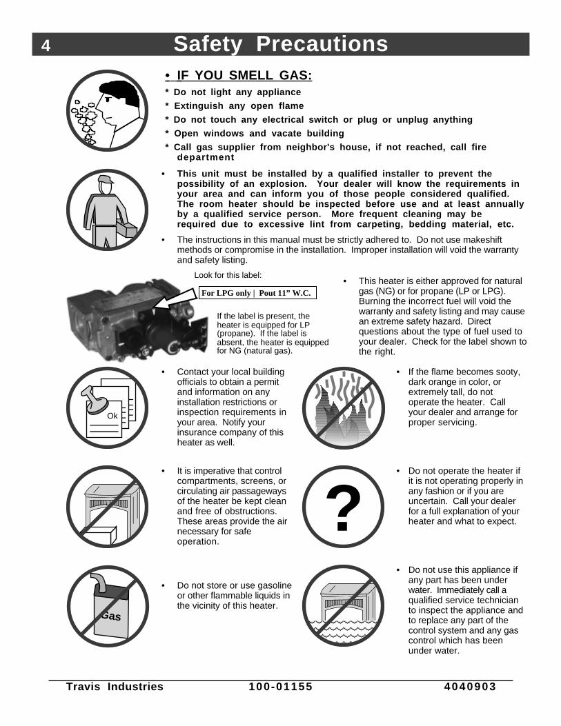
For LPG only | Pout 11” W.C.
Look for this label:
If the label is present, the heater is equipped for LP (propane). If the label is absent, the heater is equipped for NG (natural gas).
• This heater is either approved for naturalgas (NG) or for propane (LP or LPG).Burning the incorrect fuel will void thewarranty and safety listing and may causean extreme safety hazard. Directquestions about the type of fuel used toyour dealer. Check for the label shown tothe right.
Ok
• Contact your local buildingofficials to obtain a permitand information on anyinstallation restrictions orinspection requirements inyour area. Notify yourinsurance company of thisheater as well.
• If the flame becomes sooty,dark orange in color, orextremely tall, do notoperate the heater. Callyour dealer and arrange forproper servicing.
• It is imperative that controlcompartments, screens, orcirculating air passagewaysof the heater be kept cleanand free of obstructions.These areas provide the airnecessary for safeoperation.
?• Do not operate the heater if
it is not operating properly inany fashion or if you areuncertain. Call your dealerfor a full explanation of yourheater and what to expect.
Gas
• Do not store or use gasolineor other flammable liquids inthe vicinity of this heater.
AAAAAAAAAAAAAAAAA
• Do not use this appliance ifany part has been underwater. Immediately call aqualified service technicianto inspect the appliance andto replace any part of thecontrol system and any gascontrol which has beenunder water.

Safety Precautions 5
Travis Industries 100-01155 4040903
• Do not place clothing orother flammable items on ornear the heater. Becausethis heater can be controlledby a thermostat there is apossibility of the heaterturning on and igniting anyitems placed on or near it.
AAAAAAAAA
• Light the heater using thebuilt-in piezo igniter. Do notuse matches or any otherexternal device to light yourheater.
• Never remove, replace,modify or substitute any partof the heater unless
• The viewing glass should beopened only for lighting thepilot or conducting service.Do not operate with cracked,broken, or removed glass.
• Any safety screen or guardremoved for servicing mustbe replaced prior tooperating the heater.
instructions are given in thismanual. All other work mustbe done by a trainedtechnician. Don't modify orreplace orifices.
• Allow the heater to coolbefore carrying out anymaintenance or cleaning.
• Operate the heateraccording to the instructionsincluded in this manual.
• If the main burners do notstart correctly turn the gasoff at the gas control valveand call your dealer forservice.
• The pilot flame must contactthe thermopile andthermocouple (see theillustration to the left). If itdoes not, turn the gascontrol valve to "OFF" andcall your dealer.
AAA
• This unit is not for use withsolid fuel
• Do not place anything insidethe firebox (except theincluded fiber logs).
• If the fiber logs becomedamaged, replace withTravis Industries log set.
ThisManual
• Do not throw this manualaway. This manual hasimportant operating andmaintenance instructionsthat you will need at a latertime. Always follow theinstructions in this manual.
• Children and adults shouldbe alerted to the hazards ofhigh surface temperatureand should stay away toavoid burns or clothingignition. Young childrenshould be supervised whenthey are in the same room asthe heater.
• Plug the heater into a120V grounded electricaloutlet. Do not remove thegrounding plug.
• Don’t route the electricalcord in front of, over, orunder the heater
• Instruct everyone in thehouse how to shut gas off tothe appliance and at the gasmain shutoff valve. The gasmain shutoff valve is usuallynext to the gas meter orpropane tank and requires awrench to shut off.
• Travis Industries, Inc.grants no warranty,implied or stated, forthe installation ormaintenance of yourheater, and assumesno responsibility of anyconsequentialdamage(s).

6 Specifications
Travis Industries 100-01155 4040903
Features:- Ember Fyre™ Burner for "Wood Fire" Look- Works During Power Outages (millivolt system)- High Efficiency- Optional Thermostat or Remote Control- Optional Blower for Quicker Heat Distribution- Convenient Operating Controls- Variable-Rate Heat Output- Low Maintenance
Installation Options:- Freestanding Stove
- Horizontal or Vertical Vent
- Residential or Mobile Home
- Straight or Corner Placement
- Bedroom Approved
Heating Specifications:Approximate Heating Capacity (in square feet)*..............................Up to 850 with optional blower, 650 withoutMaximum BTU Input Per Hour.......................................................16,500Minimum BTU Output on Low ......................................................10,500 (NG) 9,380 (LP)Steady State Efficiency** (with optional blower on).........................up to 77.2% (NG) up to 74.5% (LP)AFUE (Annual Fuel Utilization Efficiency).......................................63% (NG) 60.7% (LP)• Heating capacity will vary depending on the home’s floor plan, degree of insulation, and the outside temperature.** Efficiency rating is a product of thermal efficiency rating determined under continuous operation independent of
installed system.
Dimensions & Weight:
14-3/4"
36-1/2"45-1/4" Leg Kit
15-1/16"
23-1/4"
28-5/8"37-3/8" Leg Kit
1-5/8"
Weight: 310 Lbs.
Electrical Specifications (for optional blower)Electrical Rating.........................................................115 Volts, 1.3 Amps, 60 Hz (150 watts on high)
Fuel:This heater is shipped in natural gas (NG) configuration but may be converted to propane (LP) usingthe included LP conversion kit. The sticker on top of the gas control valve will verify the correct fuel.

Installation (for qualified installers only) 7
Travis Industries 100-01155 4040903
Installation Warnings:! Failure to follow all of the requirements may result in property damage, bodily
injury, or even death.! This heater must be installed by a qualified installer who has gone through a
training program for the installation of direct vent gas appliances.! This appliance must be installed in accordance with all local codes, if any; if not,
follow ANSI Z223.1 and NFPA 54(88).! In Manufactured or Mobile Homes must conform with Manufactured Home
Construction and Safety Standard, Title 24 CFR, Part 3280, or, when such astandard is not applicable, the Standard for Manufactured Home Installations,ANSI/NCSBCS A225.1. This appliance may be installed in Manufactured Housingonly after the home is site located.
! This stove is designed to operate on natural gas or propane (LP).! All exhaust gases must be vented outside the structure of the living-area.
Combustion air is drawn from outside the living-area structure.! Notify your insurance company before hooking up this stove.! The requirements listed below are divided into sections. All requirements must be
met simultaneously. The order of installation is not rigid – the qualified installershould follow the procedure best suited for the installation.
Packing List• Propane Conversion Kit• Log Set• Glass Latch Tool (to un-latch glass frame)
Additional Items Required• Vent (see “Venting Requirements” for details)• Gas Line Equipment (shutoff valve, pipe, etc.)
Installation Overview
AAAAAAAAAAAAAAAAAAAAAAAAAAAAAAAAAAAAAAAAAAAAAAAAAAAAAAAAAAAAAAAAAAAAAAAAAAAAAAAAAAAAAAAAAAAAAAAAAAAAAAAAAAAAAAAAAAAAAAAAAAAAAAAAAAAAAAAAAAAAAAAAAAAAAAAAAAAAAAAAAAAAAAAAAAAAAAAAAAAAAAAAAAAAAAAAAAAAAAAAAAAAAAAAAAAAAAAAAAAAAAAAAAAAAAAAAAAAAAAAAAAAAAAAAAAAAAAAAAAAAAAAAAAAAAAAAAAAAAAAAAAAAAAAAAAAAAAAAAAAAAAAAAAAAAAAAAAAAAAAAAAAAAAAAAAAAAAAAAAAAAAAAAAAAAAAAAAAAAAAAAAAAAAAAAAAAAAAAAAAAAAAAAAAAAAAAAAAAAAAAAAAAAAAAAAAAAAAAAAAAAAAAAAAAAAAAAAAAAAAAAAAAAAAAAAAAAAAAAAAAAAAAAAAAAAAAAAAAAAAAAAAAAAAAAAAAAAAAAAAAAAAAAAAAAAAAAAAAAAAAAAAAAAAAAAAAAAAAAAA
See "Vent Requirements"
See "Floor Protection
See "Gas Line Installation"
AAAAAAAAAAAAAAAAAAAAAAAAAAAAAAAAAAAAAAAAAAAAAAAAAAAAAAAAAAAAAAAAAAAAAAAAAAAAAAAAAAAAAAAAAAAAAAAAAAAAAAAAAAAAAAAAAAAAAAAAAAAAAAAAAAAAAAAAAAAAAAAAAAAAAAAAAAAAAAAAAAAAAAAAAAAAAAAAAAAAAAAAAAAAAAAAAAAAAAAAAAAAAAAAAAAAAAAAAAAAAAAAAAAAAAAAAAAAAAAAAAAAAAAAAAAAAAAAAAAAAAAAAAAAAAAAAAAAAAAAAAAAAAAAAAAAAAAAAAAAAAAAAAAAAAAAAAAAAAAAAAAAAAAAAAAAAAAAAAAAAAAAAAAAAAAAAAAAAAAAAAAAAAAAAAAAAAAAAAAAAAAAAAAAAAAAAAAAAAAAAAAAAAAAAAAAAAAAAAAAAAAAAAAAAAAAAAAAAAAAAAAAAAAAAAAAAAAAAAAAAAAAAAAAAAAAAAAAAAAAAAAAAAAAAAAAAAAAAAAAAAAAAAAAAAAAAAAAAAAA
AAAAAAAAAAAAAAAAAAAAAAAAAAAAAAAAAAAAAAAAAAAAAAAAAAAAAAAAAAAAAAAAAAAAAAAAAAAAAAAAAAAAAAAAAAAAAAAAAAAAAAAA
See "Clearances"

8 Installation (for qualified installers only)
Travis Industries 100-01155 4040903
Installation Hints:
• If converting to LP, convert the appliance prior to installation.
• If using the optional blower, install it prior to installation.
• Install the logs last - they are fragile.
• When determining the location of the stove, locate the wall studs (for horizontal penetrations) andceiling trusses (for vertical penetrations). You may wish to adjust the stove position slightly to ensurethe vent does not intersect with a framing member.
• Fumes and smoke from the paint curing and oil burning off the steel may occur the first time you startthis heater. This is normal. We recommend you open windows to vent the room.
Stove Clearances
3" Min.
1" Min.
Straight Installations Corner Installations
Measure stove
clearances to the
stove top.
45°
1" Min.A
1" Min.
45°AA
Mobile Home Requirements
• When the stove is installed in a mobile home, it must be bolted to the floor (use the leg mounting kitwith or without legs) and the appliance grounded (use the optional blower with a grounded circuit orother suitable grounding method - current ANSI/NFPA 70).

Installation (for qualified installers only) 9
Travis Industries 100-01155 4040903
Heater Placement Requirements
• Heater must be installed on a level surface capable of supporting the heater and vent
• Due to high temperatures, the appliance should be located out of traffic and away from furnitureand draperies.
• When placed in a location where the floor to ceiling height is under 7 feet, the installation isconsidered an alcove and must meet the following requirements:- The alcove floor to ceiling height must be at least 12” above the stove top- The alcove must not be more than 30” deep before the ceiling returns to 7’- The alcove must be at least 29-1/2” wide
• The heater must not be placed so the vents below or above the door, along the sides of heater, oralong the back of the heater can become blocked.
• This heater may be placed in a bedroom. Please be aware of the large amount of heat thisappliance produces when determining a location.
Floor Protection Requirements
• The stove may be placed directly on the floor (wood, carpet, linoleum, etc.). However, westrongly recommend using floor protection under the stove (made of wood, tile, etc.)when installing on carpet or linoleum to prevent heat from dis-coloring the surface.

10 Installation (for qualified installers only)
Travis Industries 100-01155 4040903
Gas Line Installation
MASSACHUSETTS INSTALLATIONS - WARNING:
THIS PRODUCT MUST BE INSTALLED BY A LICENSED PLUYMBER OR GAS FITTER WHEN INSTALLED WITHIN THECOMMONWEALTH OF MASSACHUSETTS.OTHER MASSACHUSETTS CODE REQUIREMENTS:
• Flexible connector must not be longer than 36 inches.
• Shutoff valve must be a “T” handle gas cock.
• Only direct vent sealed combustion products are approved for bedrooms or bathrooms.
• Fireplace dampers must be removed or welded in the open position prior to the installation of a fireplace insert or gas log.
! The gas line must be installed in accordance with all local codes, if any; if not, follow current ANSIZ223.1 or NFPA 54.
! The heater and gas control valve must be disconnected from the gas supply piping during anypressure testing of that system at test pressures in excess of 1/2 psig (3.45 kPA). For pressuresunder 1/2 psig (3.45 kPA), isolate the gas supply piping by closing the manual shutoff valve.
• This heater is designed for natural gas but can be converted to propane. Check the sticker on topof the gas control valve to verify the correct fuel is used (see page 4).
• Leak test all gas line joints and the gas control valve prior to and after starting the heater.
• A manual shutoff valve is required for installation (it must be located within 3’ of the heater).T-Handle gas cocks are required in Massachusetts in compliance with code 248CMR.
• The location of the gas inlet is shown below
2-3/4"Center Line
7-1/4"
Back of Stove
The included fitting
accepts a 3/8" M.P.T.
or 1/2" F.P.T.
AAAAAAAAAAAAAAAAAAAAAAAA
Gas Inlet Pressure• With the heater off, the inlet pressure must meet the requirements listed in the table below
• If the pressure is not sufficient, make sure the piping used is large enough and the total gas loadfor the residence does not exceed the amount supplied.
• The supply regulator (the regulator that attaches directly to the residence inlet or to the propanetank) should supply gas at the suggested input pressure listed below. Contact the local gassupplier if the regulator is at an improper pressure.
Standard Input Pressure
Natural Gas 7” W.C. (1.74 Kpa)
Propane 13” W.C. (3.23 Kpa)

Installation (for qualified installers only) 11
Travis Industries 100-01155 4040903
Vent Requirements
• The vent must maintain the required clearance to combustible materials to prevent a fire (see“Clearances” below). Do not fill air spaces with insulation.
• The gas appliance and vent system must be vented directly to the outside of the building, and neverbe attached to a chimney serving a separate solid fuel or gas-burning appliance. Each direct vent gasappliance must use it's own separate vent system.
Altitude Considerations
This heater has been tested at altitudes ranging from sea level to 8,000 feet (2,400 M). In this testing we havefound that the heater, with its standard orifice, burns correctly with just an air shutter adjustment.
• Failure to adjust the air shutter properly may lead to improper combustion which can create a safety hazard.Consult your dealer or installer if you suspect an improperly adjusted air shutter.
Vent Clearances
AAAA
Min. 2" Clearance Above
45° Sloping Vent
AAAAAA
0" Clearance to the sides
after the first firestop.
AAAAAAAAAA
AAAAAA
Use a firestop whenever
passing through a
ceiling, enclosure or
floor penetration.
Use a wall thimble (#1247) when
passing through any wall.
Min. 2" Clearance
Above the Vent
AAAA
1" Clearance Below the Vent
0" Clearance to the side of vent after the
first firestop.
Part Numbers for 8” Diameter Pipe
• Use Model GS Direct Vent manufactured by Simpson Dura-Vent only . Follow the installationinstructions included with the vent. For the nearest Simpson Dura-Vent supplier, call (800) 835-4429.Vent part numbers and descriptions are listed below.
Straight Lengths1208B 6" Pipe Length, Black1207B 9" Pipe Length, Black1206B 12" Pipe Length, Black1204B 24" Pipe Length, Black1203B 36" Pipe Length, Black1202B 48" Pipe Length, Black1211B 11” to 14-5/8" Adjustable Pipe,Black
Terminations1285 Horizontal Square Termination1291 Vert. High Wind Termination1250 Vinyl Siding Stand-off
Elbows1245B 45° Elbow, Black1290B 90° Elbow, Black
Penetration, Support1247 Wall Thimble1241 Cathedral Ceiling Support Box1263 Ceiling Fire-stop1288 Wall Strap
NOTE:All measurements are for 8" diameter vent.
12-3/8" tall
10-3/4" wide with 1-3/4" to 3-3/8" overlap
16-1/4"1-3/4"
Vent Length(2', 3', etc.)
NOTE:Vent sections overlap each other by 1-3/4"
3-1/2"
Side View3-1/2"
8"
Vent Horizontal
Run
Vent Height

12 Installation (for qualified installers only)
Travis Industries 100-01155 4040903
Vent Installation
• In addition to the requirements below, follow the requirements provided with the vent.
Vertical Termination (part # 1291)
Use a roof flashing and storm collar whenever passing through the roof
Vertical Vent Requirements
Horizontal Vent Requirements
Minimum framing for fire stop
0" Clearance on Vertical Sections to combustible surfaces.
8"by8"
Use a ceiling firestop whenever passing through a ceiling (or enclosure and at every floor penetration.
Combustible Framing
Use a firestop when passing through a wall. Make sure there is a 2" clearance above the vent.
2" Min.
1" Min.
0" Clearance
Combustible Surfaces
Minimum framing for fire stop
Minimum11" tall
Minimum8" wide
• Slide the vent sections together and turn 1/4 turn until the sections lock inplace.
• Screws are not required to secure the vent. However, three screws may beused to secure vent sections together if desired.
• High temperature sealant is recommended at the appliance starter sectionconnection (use high-temperature silicone or Mill-Pac®).
• If disassembly is required, at time of re-assembly check to see if the ventcreates a tight fit. If it does not, apply high temperature sealant to the joints ofthe affected sections.
• Horizontal sections require a 1/4" rise every 12" of travel
• Horizontal sections require non-combustible support every three feet (e.g.: plumbing tape)

Installation (for qualified installers only) 13
Travis Industries 100-01155 4040903
Approved Vent Configurations
Restrictor Position
• A vent restrictor is builtinto the appliance toadjust the flow rate ofexhaust gases. Thisensures propercombustion for all ventconfigurations.Depending upon the ventconfiguration, you may berequired to adjust therestrictor position. Thecharts for acceptable ventconfigurations detail thecorrect vent restrictorposition.
To Access the Restrictor:
Remove the face (with the stove cool). You can use the glass latch tool to move the restrictor.
1
2
Determine the correct restrictor position (see the charts under "Approved Vent Configurations" - the factory position is #1).Lift up the adjustment plate and move it so the correct notch falls into the slot on the adjustment bracket.
This restrictor is in position 1 (factory setting).
Adjustment Bracket
Adjustment Plate
To adjust, lift the adjustment plate and pull it forward
Restrictor Position# 7# 6
etc...# 2
This restrictor is in position 6.
To Adjust the Restrictor:
Diffuser Plate
• Certain vent configurations require thediffuser plate to be removed. It is located inthe firebox, behind a baffle above the burner(remove the firebox liner first). Refer to thecharts for approved vent configurations todetermine if the diffuser plate requiresremoval.
c
d
Remove the baffle.
Remove the diffuser plate.
Replace the screws for the diffuser plate to seal the holes in the firebox.
Replace the baffle.
1/4" Nutdriver
AAAAAAAA
a
b

14 Installation (for qualified installers only)
Travis Industries 100-01155 4040903
Vertical Terminations
• The diffuser must beremoved.
• The termination must fallwithin the shaded areashown in the chart. Usethe indicated restrictorposition.
• If using offsets, use thetable below to calculate thevertical rise and horizontaloffset
Offset Length
Horizontal Offset
Vertical Rise
Offset Length Hor. Offset Vert. Rise
None 5” 1’
1’ Section 1’ 1’ 7”
2’ Section 1’ 9” 2’ 4”
3’ Section 2’ 5” 3’
4’ Section 3’ 2” 3’ 8”
4’ + 1’ Section 3’ 9” 4’ 4”
4’ + 2’ Section 4’ 6” 5’
4’ + 3’ Section 5’ 2” 5’ 9”
4’ + 4’ Section 6’ 6’ 9”
AAAAAAAAAAAAAAAAAAAAAAAAAAAAAAAAAAAAAAAAAAAAAAAAAAAAAAAAAAAAAAAAAAAAAAAAAAAAAAAAAAAAAAAAAAAAAAAAAAAAAAAAAAAAAAAAAAAAAAAAAAAAAAAAAAAAAAAAAAAAAAAAAAAAAAAAAAAAAAAAAAAAAAAAAAAAAAAAAAAAAAAAAAAAAAAAAAAAAAAAAAAAAAAAAAAAAAAAAAAAAAAAAAAAAAAAAAAAAAAAAAAAAAAAAAAAAAAAAAAAAAAAAAAAAAAAAAAAAAAAAAAAAAAAAAAAAAAAAAAAAAAAAAAAAAAAAAAAAAAAAAAAAAAAAAAAAAAAAAAAAAAAAAAAAAA
AAAAAAAAAAAAAAAA
AAAAAAAAAAAAAAAAAAAAAAAAAAAAAAAAAAAAAAAAAAAAAAAAAAAAAAAAAAAAAAAAAAAAAAAAAAAAAAAAAAAAAAAAAAAAAAAAAAAAAAAAAAAAAAAAAAAAAAAAAAAAAAAAAAAAAAAAAAAAAAAAAAAAAAAAAAAAAAAAAAAAAAAAAAAAAAAAAAAAAAAAAAAAAAAAAAAAAAAAAAAAAAAAAAAAAAAAAAAAAAAAAAAAAAAAAAAAAAAAAAAAAAAAAAAAAAAAAAAAAAAAAAAAAAAAAAAAAAAAAAAAAAAAAAAAAAAAAAAAAAAAAAAAAAAAAAAAAAAAAAAAA
5 feet
10 feet
15 feet
20 feet
25 feet
30 feet
0 feet
40' (max)
5 fe
et
10 fe
et
0 fe
et
5 fe
et
10 fe
et
14' (
max
)15 feet
20 feet
25 feet
30 feet
0 feet
0 fe
et
NOTE: Horizontal sections require a 1/4" rise every 12" of travel.
10 feet
40' (max)
14' (
max
)
NOTE:Restrictor positions are based upon lab tests. The ideal restrictor position may vary slightly, especially when the termination is near a demarkation line.
5 feet
NOTE: One 45° or 90° elbow may be used between horizontal sections. Horizontal length is caculated by adding each horizontal run together.
35 feet35 feet
Restrictor Position # 1
Restrictor Position # 6
Restrictor Position # 7
6' (min) 6' (min)
NOTE: Two 45° elbows may be used.

Installation (for qualified installers only) 15
Travis Industries 100-01155 4040903
Horizontal Terminations – LP (Propane)
• The diffuser must be removed.• 0 or 2 90° Elbows may be used. See "Horizontal Termination with 45° Elbow" if installing into a corner
application.• If using a Snorkel Termination (14” or 36”) add the snorkel height to the vertical height (snorkel
terminations are used primarily for basement installations).
• The termination must fall within the shaded area shown in the chart. Use the indicated restrictorposition.
AAAAAAAAAAAAAAAAAAAAAAAAAAAAAAAAAAAAAAAAAAAAAAAAAAAAAAAAAAAAAAAAAAAAAAAAAAAAAAAAAAAAAAAAAAAAAAAAAAAAAAAAAAAAAAAAAAAAAAAAAAAAAAAAAAAA
5 feet
10 feet
0 feet
0 fe
et
5 fe
et
5 feet
0 feet
0 fe
et
10 feet
5 fe
et
10 fe
et
14'
(max
)
10 fe
etRestrictor
Position # 1
14 fe
et(m
ax)
NOTE: Horizontal sections require a 1/4" rise every 12" of travel.
14 feet(max)
14 feet(max)
NOTE:Restrictor positions are based upon lab tests. The ideal restrictor position may vary slightly.

16 Installation (for qualified installers only)
Travis Industries 100-01155 4040903
Horizontal Terminations – NG (Natural Gas)
• 0 or 2 90° Elbows may be used. See "Horizontal Termination with 45° Elbow" if installing into a cornerapplication.
• If using a Snorkel Termination (14” or 36”) add the snorkel height to the vertical height (snorkelterminations are used primarily for basement installations).
• The termination must fall within the shaded area shown in the chart. Use the indicated restrictorposition.
AAAAAAAAAAAAAAAAAAAAAAAAAAAAAAAAAAAAAAAAAAAAAAAAAAAAAAAAAAAAAAAAAAAAAAAAAAAAAAAAAAAAAAAAAAAAAAAAAAAAAAAAAAAAAAAAAAAAAAAA
AAAAAAAAAAAAAAAAAAAAAAAAAAAAAAAAAAAAAAAAAAAAAAAAAAAAAAAAAAAAAAAAAAAAAAAAAAAAAAAAAAAAAAAAAAAAAAAAAAAAAAAAAAAA
5 feet
10 feet
0 feet
0 fe
et
5 fe
et
5 feet
0 feet
0 fe
et
10 feet
5 fe
et
10 fe
et
14'
(max
)
10 fe
etRestrictor
Position # 1Diffuser
Removed
14 fe
et(m
ax)
NOTE:
Horizontal sections require a 1/4" rise every
12" of travel.
NOTE:
Restrictor positions are based upon lab tests.
14 feet(max)
14 feet(max)
Restrictor Position # 1Diffuser Installed
Installation (for qualified installers only) 17
Travis Industries 100-01155 4040903
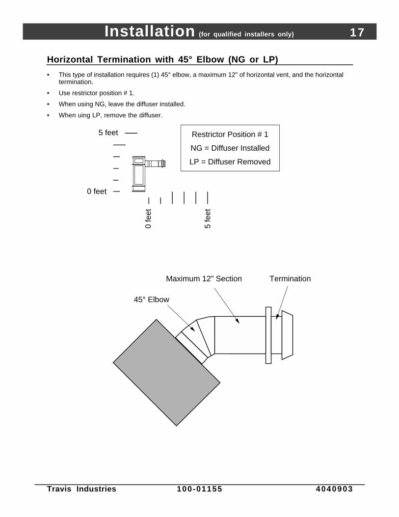
Horizontal Termination with 45° Elbow (NG or LP)
• This type of installation requires (1) 45° elbow, a maximum 12" of horizontal vent, and the horizontaltermination.
• Use restrictor position # 1.
• When using NG, leave the diffuser installed.
• When uing LP, remove the diffuser.
AAAA
5 feet
0 feet
0 fe
et
5 fe
et
Restrictor Position # 1
NG = Diffuser Installed
LP = Diffuser Removed
45° Elbow
Maximum 12" Section Termination

18 Installation (for qualified installers only)
Travis Industries 100-01155 4040903
Vent Termination Requirements (see illustration below)
! Venting terminals shall not be recessed into a wall or siding.
A Minimum 9" clearance from any door or window
B Minimum 12" above any grade, veranda, porch, deck or balcony
C Minimum 3-3/8" from outside corner wallsNOTE: Clearance in accordance with local installation codes and the requirementsof the gas supplier.
D Minimum 0" from inside corner walls
11” Min.
6” Min.
Roof Surface
Roof Eaves
E Minimum 11" clearance below unventilated soffits or roof surfacesMinimum 18" clearance below ventilated soffitsMinimum 6" clearance below roof eavesNOTE: Vinyl surfaces require 24"NOTE: Clearance in accordance with local installation codes and the requirements of the gas supplier.
F Minimum 12" clearance below a veranda, porch, deck or balconyNOTE: Permitted only if veranda, porch, deck, or balcony is fully open on a minumum of two sides beneath the floor.NOTE: Clearance in accordance with local installation codes and the requirements of the gas supplier.
G Minimum 48" clearance from any adjacent building
H Minimum 84" clearance above any grade when adjacent to public walkways or drivewaysNOTE: may not be used over a walkway or driveway shared by an adjacent building
I Minimum 48" clearance from any mechanical air supply inlet
J Minimum 36" clearance above and 48” below and to the sides of non-mechanical air supply inlet
K Minimum 36" from the area above the meter/regulator (vent outlet)NOTE: Clearance in accordance with local installation codes and the requirements of the gas supplier.
L Minimum 36" from the meter/regulator (vent outlet)NOTE: Clearance in accordance with local installation codes and the requirements of the gas supplier.
M Minimum 12” above the roof line (for vertical terminations)
N Minimum 24” horizontal clearance to any surface (such as an exterior wall) – for vertical terminations
C
B
H
E
G A
DF
L
K J
I
NOTE: Measure clearances to the nearest edge of the exhaust hood.
AE
E
M
N
• Use the vinyl siding standoff (#1250) when installing on an exterior with vinyl siding.
• Vent termination must not be located where it will become plugged by snow or other material

Finalizing the Installation (for qualified installers only) 19
Travis Industries 100-01155 4040903
1 Remove the stove top and face following the directions below.
Warning: The appliance must be completely cool prior to removing the top and face.
With both hands, lift
the stove top and
place it aside.
NOTE:
If using the
Aromatherapy
tray, remove it at
this time.
Lift the face and
off of the stove.
Four hooks on the
face insert into the
slots on the stove.
Installation Hint:
Tilt the face back, insert the bottom hooks first, then lift and insert
the top hooks. The face can then be slid down into place.
AA
HINT:
Lift the face from
under the arch -
this allows your
hand to wrap
around the face.

20 Finalizing the Installation (for qualified installers only)
Travis Industries 100-01155 4040903
2 Remove the glass following the directions below.
Warning: Do not strike or slam the glass.
Note: Verify the gasket (inside the glass frame) is intact and contacts the firebox when installed.
Open the four latches holding the glass
frame in place (start with the two below
the glass) - follow the directions shown
to the right.
a
Twist 1/4 turn.
The spring pin will
disengage from the
latch bracket,
opening the latch.
Latch Bracket
Insert the 1/4” key
into the spring
pin.
Glass
Top of Firebox
Spring Pin
Glass Frame
Lift the glass
frame up and
pull it forward to
remove.
b
Re-Attaching the Glass Frame:
a) Hang the glass frame on the firebox.
b) While holding in place, attach the upper latches
(follow the instructions to the right in reverse).
c) Lift the glass frame slightly and attach the lower latches.
NOTE:
You may need to lift the glass
frame while re-attaching.

Finalizing the Installation (for qualified installers only) 21
Travis Industries 100-01155 4040903
Glass Frame Removal and Installation (continued)
The spring pin can come loose from the latch assembly. This occurs when it is turned 1/4 turnwhen it is disengaged. Follow the directions below to re-install the spring pin if it becomes loose.
To re-install the spring pin, first
insert this end into a 1/4” key.
Insert the spring pin into
this bracket with the pins
aligned vertically.
Push in slightly and
twist 1/4 turn.
With this pin horizontal, the
spring pin will remain in place.
NOTE: The spring pins
can be installed with the
glass frame in place or
removed.

22 Finalizing the Installation (for qualified installers only)
Travis Industries 100-01155 4040903
• If converting to propane or using the firebox liner, do so now before installing the logs.
3 Install the log set following the directions below.
STEP A – Rear Log Installation
STEP B – Vertical Log Installation
The rear log restsagainst the back wall.
This notch is for thepilot assembly.
BurnerHoles
The vertical log restsagainst the back wall. The gap in the log is directly
over the burner holes.

Finalizing the Installation (for qualified installers only) 23
Travis Industries 100-01155 4040903
STEP C – Twig Installation
STEP D –Ember Installation
Place the embers in a random
pattern along the edge of the
burner. Do not place any
embers over the burner holes.
Installing the Rock Wool:
The rock wool comes in one
clump. Tear off “dime” sized
clumps and flatten. Then pull on
the wool to create gauze-like
pieces. Place them near some of
the burner holes. The wool glows
best when very thin and porous.
AAAA
AAAAAAAAA
Place the twig as shown (make surethe pin on the rear log inserts intothe hole on the twig).

24 Finalizing the Installation (for qualified installers only)
Travis Industries 100-01155 4040903
4 We recommend you purge the gas line at this time (with the glass removed). This allows gas to bedetected once it enters the firebox, ensuring gas does not build up.
5 Replace the glass.
6 Replace the face and top.
7 Turn on the gas to the fireplace. Turn on gas to the heater. Leak test all gas joints prior to starting theappliance. Start the pilot. Start the main burner. Leak test all gas joints again.
8 Check the pilot flame to make sure it looks like the illustration below. Adjust the pilot flame ifnecessary.
Standard Screwdriver
The pilot flame must contact the thermocouple and
thermopile (see the illustration below). Adjust the pilot up or
down as necessary.
To adjust the pilot flame, turn this screw. Clockwise
lowers the flame while counter-clockwise raises it.
9 Let the heater burn for fifteen minutes. Adjust the air shutter, if necessary, to achieve the correctlooking flame (see the illustration below).
• The air shutter adjusts the amount of air that mixes with the gas before it exits the burner holes.
Gas Control Valve
NOTE: If the air shutter is all the way
open, yet the flames remain sooty, shut
off gas to the fireplace and contact a
qualified gas service technician.
CorrectFlames should be blue at the
base, yellow-orange on the top.
If the flames are too tall or sooty on the
ends, open the air shutter.
Not Enough AirIf the flames are all blue and
short, close the air shutter.
Too Much Air
NOTE: The logs must be installed correctly to
monitor the flame while adjusting the air shutter.
Pushing the control to the right gives the
flame less air (closed) - making it more
orange. Pushing to the left gives the flame
more air (open), making it more blue. For
fine adjustments use a screwdriver to tap
the air shutter.
ADJUSTING THE AIR SHUTTER
Air Shutter Control

Finalizing the Installation (for qualified installers only) 25
Travis Industries 100-01155 4040903
FINE TUNING THE EMBER-FYRE™ BURNER
Each installation is affected by altitude, vent configuration, and fuel quality. Because of this, the restrictor and airshutter may need to be fine tuned to each installation. Follow the hints below to fine-tune the burner foroptimum performance and aesthetics.
Restrictor Hints:Set the restrictor to the position suggested in the vent configuration table (see pages 14-17). Turn the heateron and allow it to reach full temperature (15 min.). If the flames indicate there is excessive draft due to altitude orclimate, you may wish to adjust the restrictor to a more restrictive position (higher number). Active, flickeringshort flames are an indication of excessive draft. If the flames lift off of the burner holes, this indicates notenough draft (restrictor is set too open). After adjustments are made the unit must be cooled down to roomtemperature and restarted to make sure that the restriction is not so severe that the pilot will drop out when it isrestarted. If the pilot does drop out reduce the restriction until it will operate continuously.
Air Shutter Hints:• For more glow, open the air shutter, however, this will make the flames more blue.
• For yellow flames, close the air shutter, however, this may create less glow.
The flames should burn right off the top of the burner ports (if they are too blue, adjust the air control).
Lifting flames indicate insufficient draft (restrictor is set too high).
BurnerBurner Ports
(holes)
Ghosting flames indicate insufficient air (restrictor set too high, air shutter shut down, or other venting error).
Lifting FlamesCorrect Flames
AAAAAAAAA
AAAAAAAA
AAAAAAAAA
AAAAAAAAAAAAAAAAAA
AAAAAAAA
AAAAAAAA
AAAAAAAAA
Ghosting Flames Flickering Flames
Flickering, short flames indicate excessive draft (move air shutter to a higher position).
Warning: If the vent configuration is installed incorrectly the vent may cause the flames inside the heater to lift or“ghost” – a dangerous situation. Inspect the flames after installation to insure proper performance. If thevent configuration is correct, yet the flames are lifting or ghosting, shut off gas to the heater and contactthe dealer for information on remedying the problem.
1 0 Turn the flame adjust knob to its highest position - the flames should be approximately 10" tall. Checkthe flame on low position. The flames should burn off of each burner hole. If the heater does not workcorrectly, contact your dealer for a remedy.
1 1 Give this manual to the home owner and fully explain the operation of this heater.

26 Operation
Travis Industries 100-01155 4040903
Before You Begin
Warning: Read this entire manual before you use your new stove (especially the section "SafetyPrecautions" on pages 4 & 5). Failure to follow the instructions may result in propertydamage, bodily injury, or even death.
Warning : Do not operate appliance with the glass front removed, cracked or broken. Replacement of the glassshould be done by a licensed or qualified service person.
Location of Controls - See explanation below
Swing the control cover down to access the gas control valve and pilot igniter.
Pilot Igniter
ON/OFF Switch
Flame Adjust Knob
Gas Control Valve
Gas Control Knob
An instruction card for operating the fireplace is attached to the inside of the fireplace here. Replace it for easy reference.
Blower Control
The Pilot Flame can be found below the back log.
On/Off Switch This control is used to turn the flame on and off.
Optional Blower Control This knob controls the speed of the internal convection blower thatpushes heated air into the room.
Gas Control Knob This knob controls gas to the stove and pilot. There are three positions: ON,OFF, and PILOT. The indicator line is to the left of the knob.
Flame Adjust Knob This knob controls the flame height from low ("LO") to high ("HI”). Theindicator line is above the knob.
Pilot Igniter The pilot igniter is used only to start the pilot. When pressed, it sends anelectrical charge to the pilot assembly. This creates a blue spark directly nextto the pilot, igniting the pilot flame.
• If using a remote control or thermostat, the On/Off Switch must be left "OFF". Turning the On/OffSwitch "ON" will keep the stove on always.

Operation 27
Travis Industries 100-01155 4040903
Starting The Pilot Flame
The pilot flame is required to ignite the main burners(it also plays a safety role). It should be left ononce lit. It will stay lit unless the gas control valveis turned to "OFF". However, the pilot will go out ifthe gas is shut off, the propane tank runs out (orlow) or if the stove malfunctions. If the pilot turnsoff frequently, call your dealer for information. Tostart the pilot follow the directions below:
WARNING :When lighting or re-lighting the pilot,the glass must be removed (see page19 -20 ) .
a Remove the glass (see page 19-20 for details).
b Push the gas control knob in slightly and turn it tothe "OFF" position. The knob will not turn from"ON" to "OFF" unless the knob is depressedslightly. Wait five minutes to let any gas thatmay have accumulated inside the fireboxescape. If you smell leaking gas, follow thedirections on the cover "IF YOU SMELL GAS".
c Turn the gas control knob to the "PILOT" positionand press the knob in, this will allow gas to flow tothe pilot light. Press the button on the pilot igniterrepeatedly until you see the pilot light.
WARNING:If the pilot does not light after 15seconds, release the knob and callyour dealer for service. Do not attemptto light pilot until service has beenperformed.
NOTE:You may wish to remove the log set togain a better view of the pilot (see page2 2 ) .
d Keep the gas control knob depressed for 30seconds once it is lit.
e Release the gas control knob. If the pilot goesout, repeat step C. If the pilot refuses to stay lit,call your dealer for service. With the pilot lit,proceed to step “f”.
NOTE:If the gas control knob is turned to“OFF” after the pilot has been lit forseveral seconds, the knob will not turn.This safety feature prevents gas fromentering the firebox.
f Replace the glass.
g Turn the gas control knob counter-clockwise to"ON". The pilot is now lit and the heater can beturned on and off.
?
AAAAAAAA
AAAA
30 seconds
PILOT IGNITER
a
b
AAAAAAAA
AAAA
5 minutes
c
d
e
f
g

28 Operation
Travis Industries 100-01155 4040903
Starting the Stove for the First Time
Fumes from the Painted Surfaces CuringBurn the heater at a medium setting for approximately one hour the first time. This will cure thepainted surfaces. Fumes from the paint curing and oil burning off the steel may occur. This isnormal. We recommend you open the window to vent the room.
CondensationWater may appear on the glass each time you start the heater - this is normal.
Blue FlamesThe flames will be blue when first started. After fifteen minutes the flames will turn a more realisticyellow and orange color.
Turning the Stove On and Off
OFF
ROO
M T
EMP
°F°F
SET TE
MP
TIM
ER
MIN
Tim
eSet
Tim
eCan
cel
Au
to
OFF
ON
Use this switch to turn the main burner on and off manually.
After the pilot has been started...
See the instructions included with the remote for details on operation.
For systems with wall thermostats, use this switch to control the temperature (right is hotter, left cooler). Some systems require the on/off switch to be on.
See the instructions included with the remote for changing the battery.
Warning: Do not place combustible items on top or directly in front of the heater, even temporarily.The optional thermostat may start the heater causing a combustible item to ignite.
Note: If the heater turns on and off frequently while using the thermostat, you may want toadjust the flame height down until it produces just enough heat needed.
Adjusting the Flame Height
+ Your stove has an adjustable flame to tailor the look and heat output to your specific needs. It isadjusted by turning the middle dial on the gas control valve.
Flame Height Adjustment Knob
Index Mark
Turn counter-clockwise to adjust the flame higher, clockwise to lower.

Operation 29
Travis Industries 100-01155 4040903
Adjusting the Blower Speed (optional)
The blower helps transfer heat from the heater into the room. It will not turn on until the heater is up totemperature (approximately 10 minutes after starting). See the illustration below for instructions onadjusting the blower speed.
OFFTurn the dial all the way counter-clockwise until it clicks off.
HIGHThe high position is all the way counter-clockwise, without clicking off.
LOWTurn the dial all the way clockwise.
Normal Operating Sounds
Gas Control Valve
As the gas control valve is turned on
and off you will hear a dull clicking
sound. This is the valve opening up
and shutting down.
Blower Snap Disk
This part can produce a clicking sound as it
turns the blower on and off.
The appliance will
creak with change of
temperature.
Pilot Flame
The pilot flame,
which remains on,
makes a very slight
"whisper" sound.
Optional Blower
This heater uses a blower to push heated air into the
room. You will hear the sound of air movement that
increases as the speed is increased.
Extinction Pops
It is not unusual, especially on Propane (LP) appliances,
to experience a "pop" when the burner is shut off.
Normal Operating Odors
This appliance has several areas that reach high temperatures. Dust or other particles on these areas mayburn and create a burnt-paper smell. This is normal during startup. You may notice the smell is more acuteif the appliance was left idle for a long period.
30 Maintenance (for qualified service personnel only)
Travis Industries 100-01155 4040903
Maintaining Your Stove's AppearanceWARNING : Make sure the appliance has fully cooled prior to cleaning.
Painted Surfaces• Painted surfaces should be cleaned with a duster. If scratches occur, lightly sand the area with fine sandpaper.
Clean the area and, with the stove cool, apply one or two thin coats of stove paint to the area (mask the area toavoid overspray). Allow the stove to dry, then turn the stove on to cure the paint (1 hour on medium).
Enamel Surfaces• Use only soft cloth and water to clean enamel surfaces. To fix chips in the enamel, follow the directions below:
1) Let the stove cool. Clean the area thoroughly.2) Shake the Travis Enamel Touch-Up thoroughly. Apply to the damaged area.
Glass• Clean the glass with soap and water (do not use abrasives). To remove the glass, follow the instructions on page 19-20.
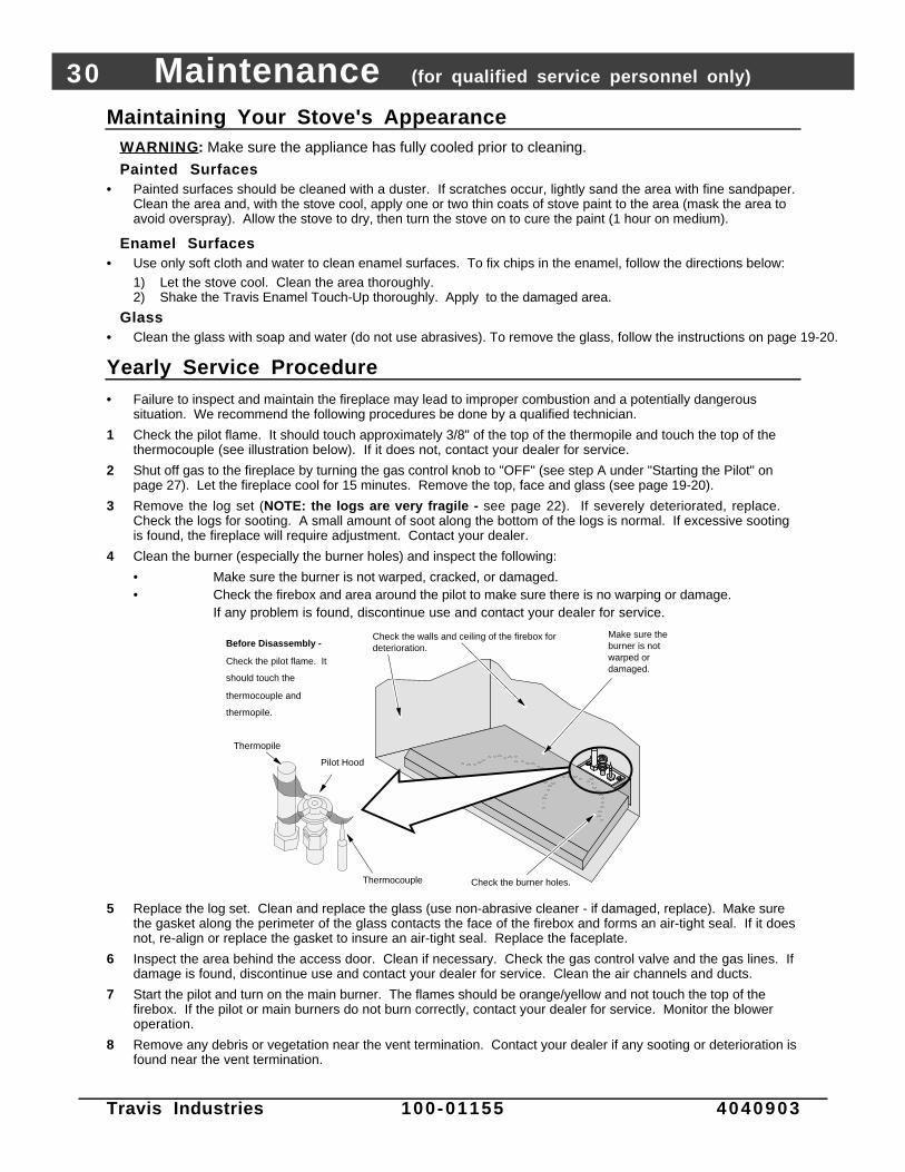
Yearly Service Procedure• Failure to inspect and maintain the fireplace may lead to improper combustion and a potentially dangerous
situation. We recommend the following procedures be done by a qualified technician.
1 Check the pilot flame. It should touch approximately 3/8" of the top of the thermopile and touch the top of thethermocouple (see illustration below). If it does not, contact your dealer for service.
2 Shut off gas to the fireplace by turning the gas control knob to "OFF" (see step A under "Starting the Pilot" onpage 27). Let the fireplace cool for 15 minutes. Remove the top, face and glass (see page 19-20).
3 Remove the log set (NOTE: the logs are very fragile - see page 22). If severely deteriorated, replace.Check the logs for sooting. A small amount of soot along the bottom of the logs is normal. If excessive sootingis found, the fireplace will require adjustment. Contact your dealer.
4 Clean the burner (especially the burner holes) and inspect the following:
• Make sure the burner is not warped, cracked, or damaged.• Check the firebox and area around the pilot to make sure there is no warping or damage.
If any problem is found, discontinue use and contact your dealer for service.
AAAA
Check the burner holes.
Make sure the burner is not warped or damaged.
Check the walls and ceiling of the firebox for deterioration.
Thermopile
Pilot Hood
Thermocouple
Before Disassembly -
Check the pilot flame. It
should touch the
thermocouple and
thermopile.
5 Replace the log set. Clean and replace the glass (use non-abrasive cleaner - if damaged, replace). Make surethe gasket along the perimeter of the glass contacts the face of the firebox and forms an air-tight seal. If it doesnot, re-align or replace the gasket to insure an air-tight seal. Replace the faceplate.
6 Inspect the area behind the access door. Clean if necessary. Check the gas control valve and the gas lines. Ifdamage is found, discontinue use and contact your dealer for service. Clean the air channels and ducts.
7 Start the pilot and turn on the main burner. The flames should be orange/yellow and not touch the top of thefirebox. If the pilot or main burners do not burn correctly, contact your dealer for service. Monitor the bloweroperation.
8 Remove any debris or vegetation near the vent termination. Contact your dealer if any sooting or deterioration isfound near the vent termination.

Maintenance (for qualified service personnel only) 31
Travis Industries 100-01155 4040903
Troubleshooting Table
Problem: Possible Cause: Don't Call for ServiceUntil You:
Pilot Will Not Light A gas shut off valve is turned off
The gas control knob isn't turned to "PILOT"
The valve control knob isn't pushed in
The igniter wasn't pressed repeatedly
No Propane in Tank
Check all gas shut off valves
See "Starting the Pilot Light" Step C
See "Starting the Pilot Light" Step C
See "Starting the Pilot Light" Step C
Check Tank Level
Main Burners Will NotStart
The pilot light has gone out
The gas control valve is turned to "PILOT" or "OFF"
The ON/OFF switch is turned to "OFF"
The remote control is not working correctly
The thermostat is set too low
See "Starting the Pilot Light"
See "Starting the Pilot Light"
Turn the ON/OFF switch to "ON"
See the remote control instructions
Set thermostat to higher temperature
Remote Control DoesNot Work
The pilot light has gone out
The gas control valve is turned to "PILOT" or "OFF"
ON/OFF switch is turned to "ON" (stove stays on)
The remote is too far away from the stove
The remote control receiver is turned "Off"
One of the two remote control batteries is dead
See "Starting the Pilot Light"
See "Starting the Pilot Light"
Turn the ON/OFF switch to "OFF"
Use the remote closer to the stove
See the remote control instructions
See the remote control instructions
Thermostat Does NotWork
The pilot light has gone out
The gas control valve is turned to "PILOT" or "OFF"
ON/OFF switch is turned to "ON" (stove stays on)
The thermostat is set too low
See "Starting the Pilot Light"
See "Starting the Pilot Light"
Turn the ON/OFF switch to "OFF"
Set thermostat to higher temperature
Optional Blower DoesNot Work
The stove is not getting electricity
The stove is not up to temperature
Check the breaker switch
See "Operating Your Stove"
Pilot Goes Out Once AMonth Or More
The gas supply has been shut off Keep the gas supply turned on
Flames Are Too Blue The stove has just been started
Improper air shutter adjustment
This is normal - see "Starting theStove for the First Time"
Adjust Air Shutter - contact yourdealer
Flames Are Too Short(Under 6")
The flame height may be turned too low Turn the flame height to "HI" -See "Adjusting the Flame Height"
Thin Layer of SootCovers the Glass
The logs or coals are placed incorrectly
Improper air shutter adjustment
See "Log Set Installation & Removal"
Adjust Air Shutter - contact yourdealer

32 Maintenance (for qualified service personnel only)
Travis Industries 100-01155 4040903
How this Stove Works
! This stove was designed with safety as the primary concern. Many of the components inside thisstove are for safety purposes. Therefore, only certified gas service technicians should service thisstove.
What Turns the Main Burners On and Off
This stove uses a millivolt system to control its operation (a millivolt is a very small amount of electricity).The thermopile and thermocouple generate electricity when heated by the pilot flame. This electricityis used to operate the gas valve. Without enough electricity, the gas valve will not turn on. That is whywhen starting the pilot the gas control knob has to be pressed in long enough for the thermocouple toheat up and generate enough electricity. The thermopile provides power for the ON/OFF switch,remote control, or thermostat (see the illustration below). Because the thermopile generates theelectricity needed to turn the stove on and off, this stove can be operated when the power is out(although the blower will not run).
When heated, the thermopile generates electricity (a very small amount measured in "Millivolts").
This electricity is used to operate the main burners. The main burners
are switched on and off using the electricity generated by the thermopile. The ON/OFF switch, remote control, or thermostat control the circuit to the main burner.
ON
OFFMA
IN B
UR
NE
R
What Prevents Gas Buildup
+ This appliance utilizes a high-technology gas valve in conjunction with a pilot flame to ensure no gasbuilds up inside the firebox.
+ The thermocouple (next to the pilot) senses when the pilot flame is lit. If the pilot flame goes out, thisthermocouple no longer generates electricity, causing the gas valve to automatically shut off all gas tothe heater, preventing the pilot from spilling gas into the firebox.
Ceramic GlassThe glass in your heater is the most durable glass available. It has been tested to be extremely resistant to breakage from temperature changes.
Gas ValveThis high-technology valve automatically shuts off all gas if it does not receive a signal from the thermocouple. If any component is damaged or sensing a malfunction, or if the wiring is damaged, it will shut off all gas.
Pilot FlameThe pilot flame is a time-proven component that eliminates the possibility of gas buildup inside the firebox.
ThermocoupleThe thermocouple generates a small amount of electricity. If the pilot flame goes out, the gas valve automatically shuts off all gas.
External Shut Off ValveThis valve is placed on the gas line to shut off gas to the appliance during maintenance procedures.

Maintenance (for qualified service personnel only) 33
Travis Industries 100-01155 4040903
Wiring DiagramCaution: Label all wires prior to disconnection when servicing controls. Wiring errors can cause
improper and dangerous operation. Verify proper operation after servicing.
120 Volt Wiring
Millivolt Wiring (for gas control valve)
Orange
White
Piezo IgniterThermopile
Red
AA
Thermocouple
Copper Co-Axial Wire
Red
Optional Remote Control
Spark Electrode
Pilot Hood
On/Off Switch
Brown
Optional Thermostat
74
109
13
Optional Blower
GreenHot (black)
Common (white)
Ground (green)
Blower Snap Disk
Power In Molex
Connector
Po
wer
Su
pp
ly
Ground (attached to stove)
White
Black
1
35
7
24
68
9
1211
10
36
White
9
25
Black
Remote Control Molex
Connector8
11
Blue
Blue
Optional Regulator Solenoid
1
4
Black
Black
7
Black
Black
10
Red
Brown
Rheostat
Gas Control Valve
Replacement Parts ListCaution: Use only Travis Industries replacement parts. Do not use substitute materials.
BLOWER MOUNT GRMT/SPACER (4)# - 1997+ PEL/1995+ GAS 93005017 LOG EMBERS, E3 - LARGE BAG # - 2001 & UP 90006819BURNER ASS'Y (EF), B33 LP/NG - 2004 & UP G29, G36, G37 226-20033 LOG EMBERS, ROCK WOOL # 93006053CONV BLOWER S-ASS'Y - G36/G37 228-10067 LOG SET, LS18 - THREE PIECE# - G29, G36, G37 172-00018CONV PARTS, LP - G29, G36, G37 - #288 225-10288 MAGNET w/OUT SHEATH - w/ MOUNTING HW 250-00002CONV PARTS, NG - G29, G36-G37 225-10313 MANUAL, SWEET DREAMS - . 100-01155DILUTION COVER ASS'Y, SWEET- - DREAMS/21 DV RV FP 221-12118 ORIFICE, BURNER - No. 49 # - 1.180" BRASS HEX (.073) 100-05210DOOR HINGE, LEFT - 16 GA EG - 2.771 x 1.106 210-05197L ORIFICE, BURNER - No. 56 # - 1.180" BRASS HEX (.0465) 100-05214DOOR HINGE, RIGHT - 16 GA EG - 2.771 x 1.106 210-05197R PAINT, NEW IRON 4oz - 24 EA/CASE 100-02403DOOR PULL - 16 GA CR - 1.805 x 1.000 210-11357 PIEZO IGNITER, ALL GAS UNITS 100-05110ENAMEL TOUCH-UP - OXFORD(BRN) - 15 ml BOTTLE 100-02406 PILOT ASS'Y, NG - S.I.T. # - COMPLETE 100-05403ENAMEL TOUCH-UP - TAUPE - 15 ml BOTTLE 100-02408 POWER CORD, w/MOLEX CONNECTOR - (TERMINATED) 100-00260FIREBOX BAFFLE - 18 GA ALZ - 13.180 x 3.352 210-05108 REMOTE HRNS PLUG, 3-LOOP # - MODULATING (12 PIN) 99300663FLUE STARTER SCTN (8" od), G29 - 2.250" TALL - 32/CARTON 172-02011 RHEOSTAT, RECTANGULAR - w/OFF - (WALL) 100-00122FUSE (BLADE) - (5) 3 AMP - # - LOW VOLTAGE - REMOTE 100-00212 SNAP-DISC - 120deg NO # - NORMALLY OPEN 100-00231GLASS LATCH ASSY, ALL UNITS - w/GLASS FRAME ASSEMBLY 221-22005 STOVE PACK, SWEET DRMS NI '03 - #376 225-10376GLASS SPRING PIN ASSY, 2004+ - ALL UNITS w/GLASS FRAME 221-22220 STOVE PACK, SWT DRMS TPE 2003 - #388 225-10388GLASS w/FRAME ASS'Y, G29/G36- - (2004) & G37 - NEW STYLE 224-21010 SWITCH, ON/OFF - SMALL, GAS # - 1996 & UP 98900747GLASS w/FRAME ASS'Y, G29/G36- - (2003) - OLD STYLE ASSY 224-21008 THERMOSTAT, RETRO KIT-NON MOD - 99300647HINGE ASS'Y COMPLT LT LG / SD 230-00765 TOOL, GLASS LATCH/RESTRICT0R/ - SCRAPER 100-02302HINGE ASS'Y COMPLT RT LG / SD 230-00766 TOOL, KEY - DIE CAST ZINC - 1/4" x 3.75" 100-02314HINGE BRKT ASS'Y, LEFT, LG/SD 230-00493 VALVE REGULATOR, LP SIT - S.I.T. # 907.211 100-05510HINGE BRKT ASS'Y, RGHT, LG/SD 230-00494 VALVE REGULATOR, NG SIT # - S.I.T. # 907.205 100-05511HW PACK, BLOWER - SWEET DREAMS - #386 225-10386 VALVE, NG - S.I.T. (2.2-3.5) - S.I.T. # 820.706 100-05509HW PACK, LEGS - SWEET DREAM - #377 225-10377 WIRE HRNS EXT, MOD REMOTE 100-00304INJECTOR, PILOT - LP (#35) # - (ORIFICE) USE w/SIT PILOT ONLY 100-05217 WIRE HRNS, MAIN - G21, G31(2), - G35, G36 - SWITCH 100-00360KNOB (PLASTIC), RHEOSTATS # - BLACK W/GOLDLINE 100-04111 WIRE HRNS, MAIN G29, G37/BLWR- - G36 (NO SWITCH) 100-00403

34 Safety Label
Travis Industries 100-01155 4040903
A copy of the safety (listing) label (adhered to the back of the stove) is shown below.
Sweet Dreams DVVented Gas
Fireplace Heater
Tested and certified by OMNI-Test Laboratories, Inc. to the combustion performance and construction requirements of ANSI Z21.88-2002, andapplicable sections of UL 307b.The Sweet Dreams DV is equipped from the factory only for use with Natural Gas. For conversion to LP (Propane) use kit supplied by themanufacturer. This appliance must be installed in accordance with all local codes, if any; if not, follow ANSI Z223.1 and NFPA 54. Installation inManufactured or Mobile Homes must conform with: Manufactured Home Construction and Safety Standard, Title 24 CFR, Part 3280. Thisappliance is only for use with the type of gas indicated on the rating plate and may be installed in an aftermarket, permanently located,manufactured (mobile) home where not prohibited by local codes. See owner’s manual for details. This appliance is not convertible for use withother gases, unless a certified kit supplied by the manufacturer is used. See owner’s manual for information on making these changes. Thisappliance uses a millivolt-type control system consisting of a gas control valve/regulator, a standing pilot burner assembly, a thermopile, athermocouple, a piezo ignitor, and the ON/OFF switch. THIS UNIT DOES NOT REQUIRE 110 VOLT POWER TO OPERATE. All exhaust gases mustbe vented outside the structure of the living-area. Combustion air is drawn from outside the living-area structure.
Vented Gas Fireplace Heater. Not for use with Solid Fuel.WARNING: Improper installation, adjustment, alteration, service or maintenance can cause injury or property damage. Refer to the owner’s informa-tion manual provided with this appliance. For assistance or additional information consult a qualified installer, service agency or the gas supplier.WARNING: Operation of this appliance when not connected to a properly installed and maintained venting system can result in carbon monoxide(CO) poisoning and possible death. Installation and repair should be performed by a qualified service person. The appliance should be inspected before use and at least annually by aqualified service person. More frequent cleaning may be required where excessive lint from material like carpeting and bedding is present.The control compartment, the burner compartment and all circulating air passageways of the appliance must be kept clean and clear at all times.This appliance must be properly connected to a venting system in accordance with the manufacturer’s installation instructions.This vented gas fireplace heater is not for use with air filters.Due to high temperatures, the appliance should be located out of traffic and away from furniture and draperies.Children and adults should be alerted to the hazards of high surface temperature and should stay away to avoid flesh burns or clothing ignition.Young children should be carefully supervised at all times when they are in the same room as the appliance.Use direct vent systems listed in owner’s manual to vent this appliance to the exterior.
CAUTION: Hot while in operation. Do not touch. Keep children, clothing, furniture, gasoline and other liquids having flammable vapors away. Do not operate this appliancewith glass removed, cracked or broken. Replacement of the panel(s) should be done by alicensed or qualified service person.
L.P. N.G. L.P. N.G.Input Rate on “HI” (BTU/Hr) . . . . . . . 16,500 16,500 Minimum Inlet Pressure (inches W.C.) . . . . . . . . 11.5” 5.5”Input Rate on “LO” (BTU/Hr) . . . . . . 12,800 13,800 Maximum Inlet Pressure (inches W.C.) . . . . . . . . 13” 7”Orifice Size . . . . . . . . . . . . . . . . . . . . DMS 56 DMS 49 Manifold Pressure on “HI” (inches W.C.) . . . . . . 11” 3.5”
This appliance is equipped for installation from 0-2000 ft. For altitudes above 2,000 feet, the ventconfiguration, orifice, or combination of both may need to be changed. See owner’s manual for information on makingthese changes.
FAN TYPE VENTED CIRCULATORBlower Electrical Rating: 115V., 1.5 Amps, 60 Hz
4800 Harbour Pointe Blvd. SW Mukilteo, WA 98275
Minimum Clearances to CombustiblesUnit to Sidewall .............................. 3” Alcove Min. Height............................... 48”Unit to Backwall ............................. 1” Alcove Max. Depth............................... 30”Unit to Cornerwall .......................... 1” Alcove Min Width................................. 29.5”Front of Unit ................................... 36”
Manufacture 2004 Jan. Apr. Jul. Oct.Date: 2005 Feb. May Aug. Nov.
2006 Mar. Jun. Sep. Dec. 0523IGN
Report No. 028-S-55-5
A copy of the instruction label (on a tag near the gas control valve) is shown below.
If the pilot will not stay lit after several tries, turn the gas control knob to"OFF" and call your service technician or gas supplier.
9. Turn the gas control knob counterclockwise to "ON".
10. Turn on the blower (room air fan) on the appliance.
11. Set the thermostat to desiredsetting (if applicable) or use the ON/OFF rocker switch orremote control to operate the main burner.
1. STOP! Read the safety information to the left and at the bottomof this label before proceeding.
2. Set the thermostat to lowestsetting (if applicable).
3. Turn off the blower (room air fan)on the appliance (if applicable).
4. Push the gas control knob inslightly and turn it clockwise tothe "OFF" position.
NOTE: The knob will not turnfrom "ON" to "OFF" unless theknob is depressed slightly. Donot force.
5. Wait five (5) minutes to clear outany gas. Then smell for gas,including near the floor. If yousmell gas, STOP! Follow "B" inthe safety information to the lefton this label. If you don't smellgas, go to the next step.
6. Turn gas control knobcounterclockwise to the "PILOT" position.
7. A) Press the knob in and hold.
B) Immediately press the igniter button repeatedly until the pilot is lit. WARNING: If the pilot doesnot light after 15 seconds, release the knob and call your dealerfor service.
C) Keep the gas control knobdepressed for 30 seconds once the pilot is lit.
8. Release the gas control knob. If the pilot goes out, repeat step 7.
• If the knob does not pop up when released, stop andimmediately call your service technician or gas supplier.
A. This appliance is equipped with an ignition device which must be lighted by hand.When lighting the pilot, follow these instructions exactly.
B. BEFORE LIGHTING, smell all around the appliance area for gas. Be sure to smell nextto the floor because some gas is heavier than air and will settle on the floor.
WHAT TO DO IF YOU SMELL GAS:
• Do not try to light any appliance.
• Do not touch any electric switch; do not use any phone in your building.
• Immediately call your gas supplier from a neighbor's phone. Follow the gassupplier's instructions.
• If you cannot reach your gas supplier, call the fire department.
C. Use only your hand to push in or turn the gas control knob. Never use tools. If theknob will not push in or turn by hand, don't try to repair it, call a qualified servicetechnician. Force or attempted repair may result in a fire or explosion.
D. Do not use this appliance if any part has been under water. Immediately call a qualifiedservice technician to inspect the appliance and to replace any part of the controlsystem and any gas control which has been under water.
E. Do not block any control compartments, screens or circulating air passageways.These areas provide air necessary for safe operation.
DO NOT REMOVE THIS INSTRUCTION PLATE
1. Set the thermostat to lowest setting(if applicable).
2. Turn off the blower (room air fan) on theappliance.
3. Push the gas control knob in slightly andturn it clockwise to the "OFF" position.
NOTE: The knob will not turn from "ON" to"OFF" unless the knob is depressed slightly.Do not force.
FOR YOUR SAFETY READ BEFORE LIGHTING LIGHTING INSTRUCTIONS TO TURN OFF GAS TO APPLIANCE
69
3
7C
7A 7B
4
WARNING: IF YOU DO NOT FOLLOW THESE INSTRUCTIONS EXACTLY, A FIRE OR EXPLOSION MAY RESULT, CAUSING PROPERTY DAMAGE, PERSONALINJURY OR LOSS OF LIFE. WHEN LIGHTING OR RE-LIGHTING THE PILOT, THE DOOR MUST BE OPEN OR THE GLASS REMOVED. AFTER THE PILOTIS LIT, CLOSE AND LATCH THE DOOR OR REPLACE THE GLASS BEFORE LIGHTING THE BURNER. 0330

Limited 7 Year Warranty 35
Travis Industries 100-01155 4040903
To register your TRAVIS INDUSTRIES, INC. 7 Year Warranty, complete the enclosed warranty card and mail it within ten (10) days of the appliancepurchase date to: TRAVIS INDUSTRIES, INC., 4800 Harbour Pointe Blvd. SW, Mukilteo, WA 98275. TRAVIS INDUSTRIES, INC. warrants this gasappliance (appliance is defined as the equipment manufactured by Travis Industries, Inc.) to be defect-free in material and workmanship to the originalpurchaser from the date of purchase as follows:
Check with your dealer in advance for any costs to you when arranging a warranty call.Mileage or service charges are not covered by this warranty. This charge can vary from store to store.
Years 1 & 2 - COVERAGE: PARTS & LABORBurner Assembly:Burner Pan, Mixing Tube, Air Shutter Assembly, MainBurner Orifice
Firebox Assembly:Adjustable Air Restrictor, Pressure Relief Mechanisms(direct vents only), Glass Attachment Mechanism
Gas Control AssemblyAdjustable control valve, millivolt wiring and connectors(located within the metal heater structure), thermopile,thermocouple, pilot hood, orifices, pilot gas line, piezoignitor
Ceramic GlassGlass (breakage from thermal shock)
Ceramic LogsLog Set, Coals, Ember Strip (Steel Fiber)
Gold PlatingGold or Nickel Door, Optional Grill (see “Conditions and Exclusions” # 9)
Electrical Assembly : Blower, wiring harness, snap discs, rheostat speed control
AccessoriesLegs, Cast Firebacks
Convection Heat Exchanger
Re-Installation AllowanceIn cases where heater must be removed from home forrepairs, a partial cost of re-installation is covered (pre-authorization required)
One-Way Freight AllowanceOne-way freight allowance on pre-authorized repair done atfactory is covered.
Exclusions: Paint, Gasketing
Years 3 THROUGH 5 - COVERAGE: PARTS & LABORFirebox Assembly:Adjustable Air Restrictor, Pressure Relief Mechanisms (directvents only), Glass Attachment Mechanism
Convection Heat Exchanger One-Way Freight AllowanceOne-way freight allowance on pre-authorized repair done atfactory is covered.
Exclusions: Paint, Gasketing, Burner Assembly, Electrical Assembly, Gas Control Assembly, Ceramic Glass, Ceramic Logs, Gold & NickelPlating, Accessories, Re-Installation Allowance
Years 6 & 7 - COVERAGE: PARTS ONLYFirebox Assembly:Adjustable Air Restrictor, Pressure Relief Mechanisms (direct vents only), Glass Attachment Mechanism
Exclusions: Paint, Gasketing, Burner Assembly, Electrical Assembly, Gas Control Assembly, Ceramic Glass, Ceramic Logs, Gold & NickelPlating, Accessories, Convection Heat Exchanger, Re-Installation Allowance, One-Way Freight Allowance, Labor
CONDITIONS & EXCLUSIONS1. This new gas appliance must be installed by a qualified gas appliance technician. It must be installed, operated, and maintained at all times in accordance with the instructions in the Owner’s
Manual. Any alteration, willful abuse, accident, neglect, or misuse of the product shall nullify this warranty.2. This warranty is nontransferable, and is made to the ORIGINAL purchaser, provided that the purchase was made through an authorized TRAVIS dealer.3. Discoloration and some minor expansion, contraction, or movement of certain parts and resulting noise, is normal and not a defect and, therefore, not covered under warranty. The installer
must ensure the appliance is burning as per the rating tag at the time of installation. Over-firing (operation above the listed BTU rate) of this appliance can cause serious damage and will nullifythis warranty.
4. The warranty, as outlined within this document, does not apply to the chimney components or other Non-Travis accessories used in conjunction with the installation of this product. If in doubt asto the extent of this warranty, contact your authorized TRAVIS retailer before installation.
5. Travis Industries will not be responsible for inadequate performance caused by environmental conditions such as nearby trees, buildings, roof tops, wind, hills or mountains or negative pressureor other influences from mechanical systems such as furnaces, fans, clothes dryers, etc.
6. This Warranty is void if:a. The unit has been operated in atmospheres contaminated by chlorine, fluorine or other damaging chemicals.b. The unit is subject to submersion in water or prolonged periods of dampness or condensation.c. Any damage to the unit, combustion chamber, heat exchanger or other components due to water, or weather damage which is the result of, but not limited to, improper chimney/venting
installation.7. Exclusions to this 7 Year Warranty include: injury, loss of use, damage, failure to function due to accident, negligence, misuse, improper installation, alteration or adjustment of the
manufacturer's settings of components, lack of proper and regular maintenance, damage incurred while the appliance is in transit, alteration, or act of God.8. This 7 Year warranty excludes damage caused by normal wear and tear, such as paint discoloration or chipping, worn or torn gasketing, corroded or cracked logs, embers, etc. Also excluded is
damage to the unit caused by abuse, improper installation, modification of the unit, drilling of the orifices, or the use of fuel other than that for which the unit is configured. Units are shipped fornatural gas and must be converted to propane using the included conversion kit. Confirm fuel configuration with your installer.
9. Damage to gold, nickel, or brass surfaces caused by fingerprints, scratches, melted items, or other external sources left on the surface is not covered in this warranty. Damage from the useof cleaners other than denatured alcohol on gold or nickel is not covered in this warranty. Damage from the use of abrasive cleaners on brass is not covered in this warranty.
10. TRAVIS INDUSTRIES, INC. is free of liability for any damages caused by the appliance, as well as inconvenience expenses and materials. Incidental or consequential damages are not coveredby this warranty. In some states, the exclusion of incidental or consequential damage may not apply.
11. This warranty does not cover any loss or damage incurred by the use or removal of any component or apparatus to or from the gas appliance without the express written permission of TRAVISINDUSTRIES, INC. and bearing a TRAVIS INDUSTRIES, INC. label of approval.
12. Any statement or representation of TRAVIS products and their performance contained in TRAVIS advertising, packaging literature, or printed material is not part of this 7 year warranty.13. This warranty is automatically voided if the appliance’s serial number has been removed or altered in any way. If the appliance is used for commercial purposes, it is excluded from this warranty.14. No dealer, distributor, or similar person has the authority to represent or warrant TRAVIS products beyond the terms contained within this warranty. TRAVIS INDUSTRIES, INC. assumes no
liability for such warranties or representations.15. Travis Industries will not cover the cost of the removal or re-installation of hearths, facing, mantels, venting or other components.16. If for any reason any section of this warranty is declared invalid, the balance of the warranty remains in effect and all other clauses shall remain in effect.17. THIS 7 YEAR WARRANTY IS THE ONLY WARRANTY SUPPLIED BY TRAVIS INDUSTRIES, INC., THE MANUFACTURER OF THE APPLIANCE. ALL OTHER WARRANTIES,
WHETHER EXPRESS OR IMPLIED, ARE HEREBY EXPRESSLY DISCLAIMED AND PURCHASER’S RECOURSE IS EXPRESSLY LIMITED TO THE WARRANTIES SET FORTHHEREIN.
IF WARRANTY SERVICE IS NEEDED:1. If you discover a problem that you believe is covered by this warranty, you MUST REPORT it to your TRAVIS dealer WITHIN 30 DAYS, giving them proof of purchase, the purchase date,
and the model name and serial number.2. Travis Industries has the option of either repairing or replacing the defective component.3. If your dealer is unable to repair your appliance’s defect, he may process a warranty claim through TRAVIS INDUSTRIES, INC., including the name of the dealership where you purchased the
appliance, a copy of your receipt showing the date of the appliance’s purchase, and the serial number on your appliance. At that time, you may be asked to ship your appliance, freight chargesprepaid, to TRAVIS INDUSTRIES, INC. TRAVIS INDUSTRIES, INC., at its option, will repair or replace, free of charge, your TRAVIS appliance if it is found to be defective in material orworkmanship within the time frame stated within this 7 year warranty. TRAVIS INDUSTRIES, INC. will return your appliance, freight charges (years 1 to 5) prepaid by TRAVIS INDUSTRIES,INC., to your regional distributor, or dealership.
4. Check with your dealer in advance for any costs to you when arranging a warranty call. Mileage or service charges are not covered by this warranty. This charge can vary from store to store.

36 Optional Equipment (for qualified installers only)
Travis Industries 100-01155 4040903
Optional Accessories:• Leg Kit, Tall, Cast Iron, New Iron SKU# 99500115• Leg Kit, Tall, Cast Iron, Oxford Brown Enamel SKU# 99500118• Leg Kit, Tall, Cast Iron, Taupe Enamel SKU# 99500119• Leg Mounting Kit, Sweet Dreams, SKU# 99500110 (See instructions below)• Door, Double Door, New Iron, Sweet Dreams/Looking Glass SKU# 99300446• Door, Double Door, Oxford Brown, Sweet Dreams/Looking Glass SKU# 99300447• Door, Double Door, Taupe, Sweet Dreams/Looking Glass SKU# 99300448• Stone Kit, Travertine, Sweet Dreams SKU# 99600218• Cast Kit, Sweet Dreams - Oxord Brown Top & Side Plates SKU# 99600222• Cast Kit, Sweet Dreams - Taupe Top & Side Plates SKU# 99600223• Mirror Glass, SKU# 99300481• Grill, Arabesque - Ant Gold SKU# 91002145• Grill, Arabesque - Pewter SKU# 91002146• Interior, Travertine SKU# 98500668• Interior, Brick Beehive SKU# 98500669• Interior, Shell - Almond SKU# 98500670• Wall thermostat SKU# 99300650• Remote Thermostat SKU# 99300653• Aromatherapy Tray Option• Aromatherapy Essential Oils Kit

Optional Equipment (for qualified installers only) 37
Travis Industries 100-01155 4040903
LP Conversion Instructions
Install the conversion kit prior to installing the gas line to ensure proper gas use.
1 Remove the face and glass (see page 19-20). Remove the logs and coals (if installed - page 22)
2 Remove the burner (see illustration below).
The mixing tube slides onto the orifice.
Burner Replacement:
AAAAAAAA
Lift up on the left side of the burner, then slide the burner to the left and up to remove.
AAAAAAAA
Make sure the screw on the bottom of the burner inserts into this hole.
Before replacing the burner, slide the air control all the way to the right.
Lift the pilot hood off the pilot assembly (you may need to pull hard to remove).
b
a
After replacing the burner re-attach the pilot hood.
Make sure the burner is fully seated and pilot hood lines up with the burner holes at the rear edge of theburner.

38 Optional Equipment (for qualified installers only)
Travis Industries 100-01155 4040903
3 Follow the directions below to replace the orifice.
AAAAAAAAA
a
Slide the air shutter all the way to the left.
Burner Orifice
Manifold
1/2" Wrench
Use a 1/2” open end wrench to unscrew the burner orifice.
NOTE:Screw the LP orifice in so the orifice shoulder protrudes 5/16” (indicating full insertion).
4956
The new LP orifice has “56” stamped on it.
The old NG orifice has “49” stamped on it.
Apply thread sealant to the new orifice and install.
5/16”
d e
4 Remove the pilot orifice following the instructions below. Replace with the propane pilot orifice
Lift the pilot hood
off the pilot
assembly.
5/32" Hex
Use a hex wrench to
unscrew the orifice.
Remove the orifice and replace with the LP orifice. Screw the
orifice all the way in and replace the pilot hood.
LP (Propane) Orifice
Orifice Identification:
NG (Natural Gas) Orifice
35
62
35
a
b
c
NOTE: when re-attaching,
this pin lines up with the
notch in the pilot hood.

Optional Equipment (for qualified installers only) 39
Travis Industries 100-01155 4040903
5 Install the logs andembers.
6 Replace glass andface.
7 Remove theregulator from thefront of the gascontrol valve.Replace with thepropane regulator,using the newgasket and screwsincluded with theregulator. NOTE:Leak test thisarea after theheater isinstalled, gas isconnected,and the mainburner is lit.
Place the LP label on top of
the control cover near the gas
control valve.
d
Remove and discard the three screws using a
slotted screwdriver of Torx T-20.
NOTE: Make sure the
regulator gasket is correctly
aligned before installation.
Remove and discard the
regulator, diaphram, spring
and center post.
a
b
Slotted Screwdriver(or T-20 Torx)
Install the LP regulator. Use the screws
included with the LP regulator. Tighten to
approximately 25 Lbs. torque.
c
Slotted Screwdriver(or T-20 Torx)
9 Make the gas line connection, bleed the gas line (if applicable), start the heater and thoroughly leak-test all gas connections and the gas control valve. Check the pilot. Adjust if necessary.
WARNING: When lighting or re-lighting the pilot, the glass must be removed (seepage 19-20).
Standard Screwdriver
The pilot flame must contact the thermocouple and
thermopile (see the illustration below). Adjust the pilot up or
down as necessary.
To adjust the pilot flame, turn this screw (NOTE: if totally
unscrewed gas will come out of this port). Clockwise
lowers the flame while counter-clockwise raises it.

40 Optional Equipment (for qualified installers only)
Travis Industries 100-01155 4040903
Blower (SKU 99000158)
PACKING LIST
• Blower with Mounting Plate • Wiring Harness with Strain Relief Plate & Power Cord
• Four (4) # 8-32 Center Lock Nuts • Two (2) # 8 x 3/8” HWHSSMS Screws
• Four (4) Grommets & Bushings • Rheostat with Nut, Washer, and Knob
INSTALLATION INSTRUCTIONS
WARNING: Make sure the gas has been shut off, power disconnected, and the appliance iscool prior to conducting service.
1 Remove the access panel on the back of the stove.
1/4" Nutdriver
2 Insert the wiring harness, with strain relief plate attached, through the hole on the back of the stove.Then attach the strain relief plate to the back plate with the included screws.
1/4" Nutdriver
Wiring Harness
Strain Relief Plate
NOTE: the wiring harness should be
directed inwards, through an access hole
near the back of the gas control valve.
NOTE: The grounding
wire is attached to the
strain relief plate.

Optional Equipment (for qualified installers only) 41
Travis Industries 100-01155 4040903
3 Attach the blower wires and grommets following the directions below.
Insert the bushings
into the 4 grommets. Slide the 4 grommets onto
the blower mounting plate.
Attach the two wires
labeled "BLOWER" to
the blower.
a BLO
WE
R
bc
Blower
Mounting
Plate
4 Attach the blower (with blower plate) following the directions below.
Secure the blower to the stove with the 4 nuts
included with the blower.
11/32" Nutdriver
5 Replace the access panel (see step # 1 above).6 Remove the control cover and discard the on/off wires following the directions below.
Phillips Screwdriver
Back of on/off switch
Gas Control Valve
a
b
Remove the control cover and place it in front of the stove.
Remove and discard the wires leading from the gas control valve to the on/off switch.

42 Optional Equipment (for qualified installers only)
Travis Industries 100-01155 4040903
7 Install the rheostat onto the control cover.
1/2" Wrench
NOTE: this tab fits
into the hole on the
control cover.
Attach the rheostat to the control co
with the included nut and star washe
Attach
the kn
LOW
OFF
BLOWER
b
cHI
Remove the button plug
from the control cover.
LOW
OFF
HI
BLOWER
a
8 Attach the wiring harness to the gas control valve, on/off switch, rheostat, and snap disc switchfollowing the directions below.
Back of
on/off switch
Gas Control Valve
LOW
OFF
HI
BLOWER
Rheostat
Wires
VALVE
RHEOSTAT
SNAP
DIS
C
Snap Disc
9 Position the wiring harness under the burner and re-attach the control cover (see step # 6 above).Make sure the wiring harness does not contact the burner or blower.
10 Turn on the appliance and check operation (the blower will not turn on until the stove is at fulltemperature – 15 minutes on high).

Optional Equipment (for qualified installers only) 43
Travis Industries 100-01155 4040903
Leg Mounting Kit (SKU 99500110)
NOTE: The legs must be purchased separately.
PACKING LIST
• Two (2) Leg Mounting Plates • Four (4) 1/4-20 x 1/2” Bolts with 1/4” Washers
• Four (4) 3/8-16 Nuts with 3/8” Washers • Four (4) Rubber Tipped Leveling Bolts
INSTALLATION INSTRUCTIONS
NOTE: Install this kit prior to installing the Sweet Dreams stove.
1 Remove the stove top and face (see the owner’s manual for details).
2 Attach the legs (and rubber-tipped leveling bolts) to the leg mounting plates following the directionsbelow. The clips on the mounting plates insure proper leg alignment.
Leveling Bolts
Leg Nuts & Washers
Leg Mounting Plates
9/16" Wrench
3 Place two pieces of wood (or other spacer, pallet, etc…) behind the stove. Tilt the stove back until itrests on the wood (see the illustration below). Attach the leg mounting plates (and legs) to the stove.
AAAAAAAAAAAAAAAAAAAAAAAAAAAAAAAAAAAAAAAAAAAAAAAAAAAAAAAAAAAAAAAAAAAAAAAAAAAAAAAAAAAAAAAAAAAAAAAAAAAAAAAAAAAAAAAAAAAAAAAAAAAAAAAAAAAAAAAAAAAAAAAAAAAAAAAAAAAAAAAAAAAAAAAAAAAAAAAAAAAAAAAAAAAAAAAAAAAAAAAAAAAAAAAAAAAAAAAAAAAAAAAAAAAAAAAAAAAAAAAA
AAAAAAAAAAAAAAAAAAAAAAAAAAAAAAAAAAAAAAAAAAAAAAAAAAAAAAAAAAAAAAAAAAAAAAAAAAAAAAAAAAAAAAAAAAAAAAAAAAAAAAAAAAAAAAAAAAAAAAAAAAAAAAAAAAAAAAAAAAAAAAAAAAAAAAAAAAAAAAAAAAAAAAAAAAAAAAAAAAAAAAAAAAAAAAAAAAAAAAAAAAAAAAAAAAAAAAAAAAAAAAAAAAAAAAAAAAAAAAAAAAAAAAA
AAAAAAAA
7/16" Wrench
Wood (or other spacer)
4 Restore the stove to an upright position, taking care to prevent undue weight on the legs. Once thestove is in position, unscrew the leveling bolts to level the stove (NOTE: do not slide the stove – thismay damage the bolts or the mounting plates). The rubber tips also prevent noise from vibration.

44 Index
Travis Industries 100-01155 4040903
Approved Vent Configurations..........................13-16
Adjusting the Blower Speed..............................29
Adjusting the Flame Height ...............................28
Air Shutter Adjustment......................................24
Altitude Considerations.....................................11
Blower Control..................................................29
BTU Input.........................................................6
BTU Output......................................................6
Cap (see vent termination).................................18
Chimney Cap (see vent termination)...................18
Clearances.......................................................8
Condensation on Glass.....................................28
Corner Installation.............................................8
Dimensions......................................................6
Dura-Vent (part numbers)..................................12
Elbows.............................................................12
Face Removal...................................................19
Finalizing the Installation....................................19
Floor Protection ...............................................9
Fuel .................................................................3
Gas Control Valve (Location)..............................26
Gas Inlet Pressure.............................................10
Gas Line Connection ........................................10
Gas Line Install..................................................10
Gas Smell .................................See Inst. on Cover
Glass Installation and Removal ...........................19
Hearth Requirements........................................9
Heating Specifications ......................................6
Horizontal Vent Termination Requirements ........18
How this Stove Works .......................................32
Installation Options ...........................................6
Items Required for Installation............................7
Leaking Gas .............................See Inst. on Cover
Listing Information ............................................34
Location of Controls..........................................26
Log Set Installation and Removal .......................22
Maintenance ....................................................30
Noise (see Normal Operating Sounds) ...............29
Normal Operating Sounds.................................29
Packing List......................................................7
Pilot Flame Inspection.......................................24
Piping Installation (see Gas Line Install)...............10
Restrictor Position ............................................13
Safety Label.....................................................34
Safety Precautions ...........................................3
Starting The Pilot ..............................................27
Starting the Stove for the First Time ...................28
Thermostat Operation.......................................28
Turning the Stove On and Off............................28
Vent Length (see “Vent Config.”) ......................13
Vent Part Numbers ...........................................12
Vent Requirements ..........................................11
Vertical Vent Termination Requirements ............18
Warnings..........................................................3
Warranty...........................................................35
Water on Glass (see Condensation) ...................28
Weight.............................................................6
What Prevents Gas Buildup...............................32
What Turns the Main Burners On and Off............32
Wiring Diagram..................................................33
Yearly Service Procedure..................................30