Embed Size (px)
Citation preview
INTRODUCTION TO WIRELESS LAN, MAC PROTOCOLS and [email protected], Choong Seon Hong, KHU
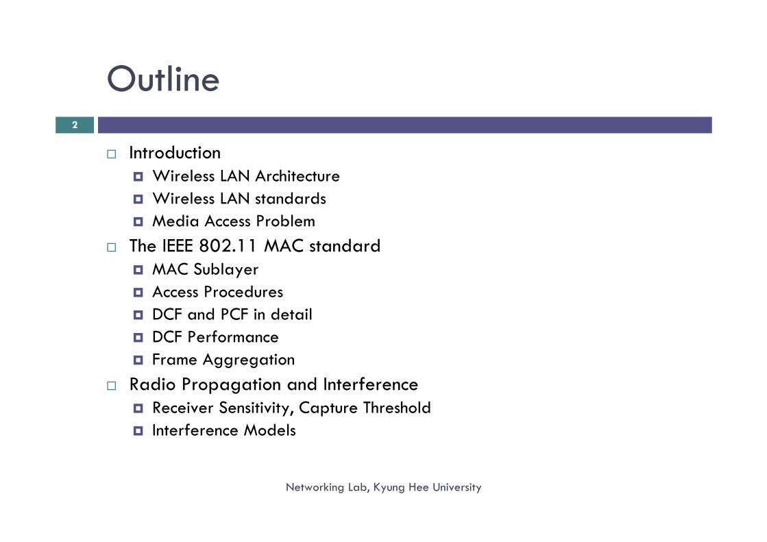
Outline
IntroductionWireless LAN ArchitectureWireless LAN standardsMedia Access Problem
The IEEE 802.11 MAC standardMAC SublayerAccess ProceduresDCF and PCF in detailDCF PerformanceFrame Aggregation
Radio Propagation and InterferenceReceiver Sensitivity, Capture ThresholdInterference Models
2
Networking Lab, Kyung Hee University
3
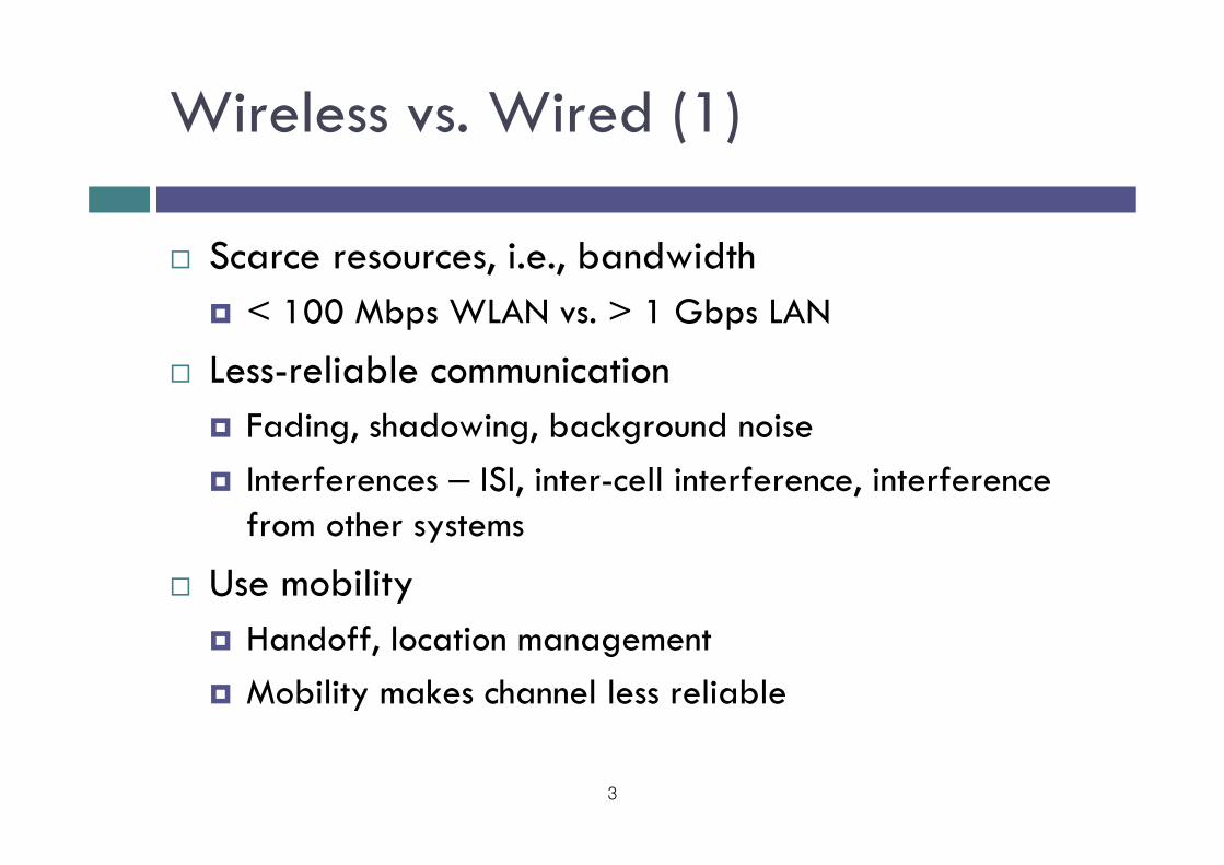
Wireless vs. Wired (1)
Scarce resources, i.e., bandwidth< 100 Mbps WLAN vs. > 1 Gbps LAN
Less-reliable communicationFading, shadowing, background noiseInterferences – ISI, inter-cell interference, interference from other systems
Use mobilityHandoff, location managementMobility makes channel less reliable
4
Wireless vs. Wired (2)
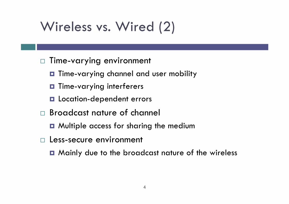
Time-varying environmentTime-varying channel and user mobilityTime-varying interferersLocation-dependent errors
Broadcast nature of channelMultiple access for sharing the medium
Less-secure environmentMainly due to the broadcast nature of the wireless
5
Wireless vs. Mobile
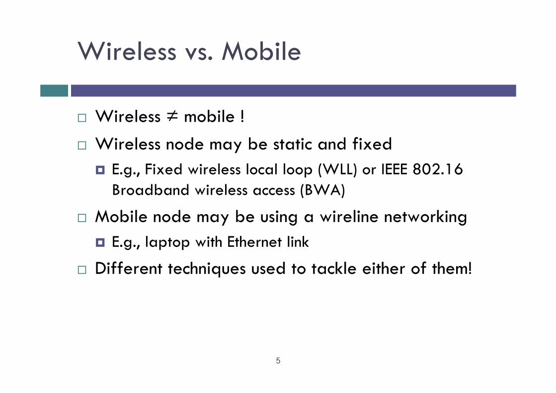
Wireless ≠ mobile !Wireless node may be static and fixed
E.g., Fixed wireless local loop (WLL) or IEEE 802.16 Broadband wireless access (BWA)
Mobile node may be using a wireline networkingE.g., laptop with Ethernet link
Different techniques used to tackle either of them!
6
Wireless & Mobile Networks
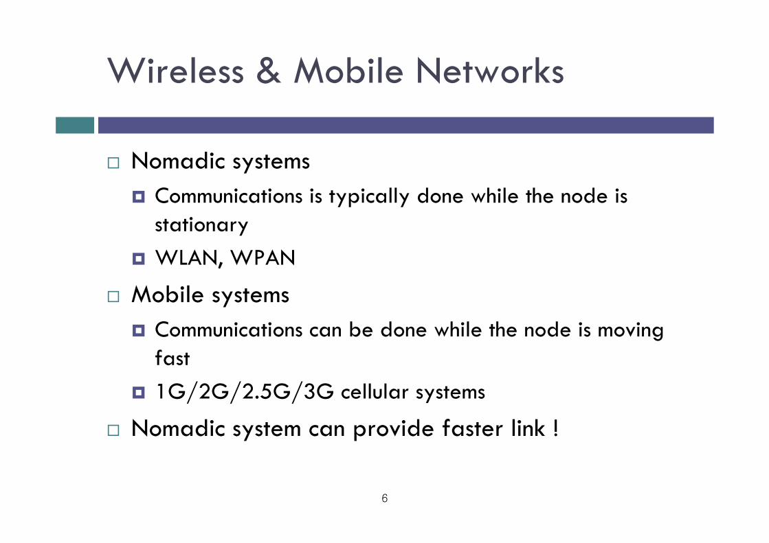
Nomadic systemsCommunications is typically done while the node is stationaryWLAN, WPAN
Mobile systemsCommunications can be done while the node is moving fast1G/2G/2.5G/3G cellular systems
Nomadic system can provide faster link !
7
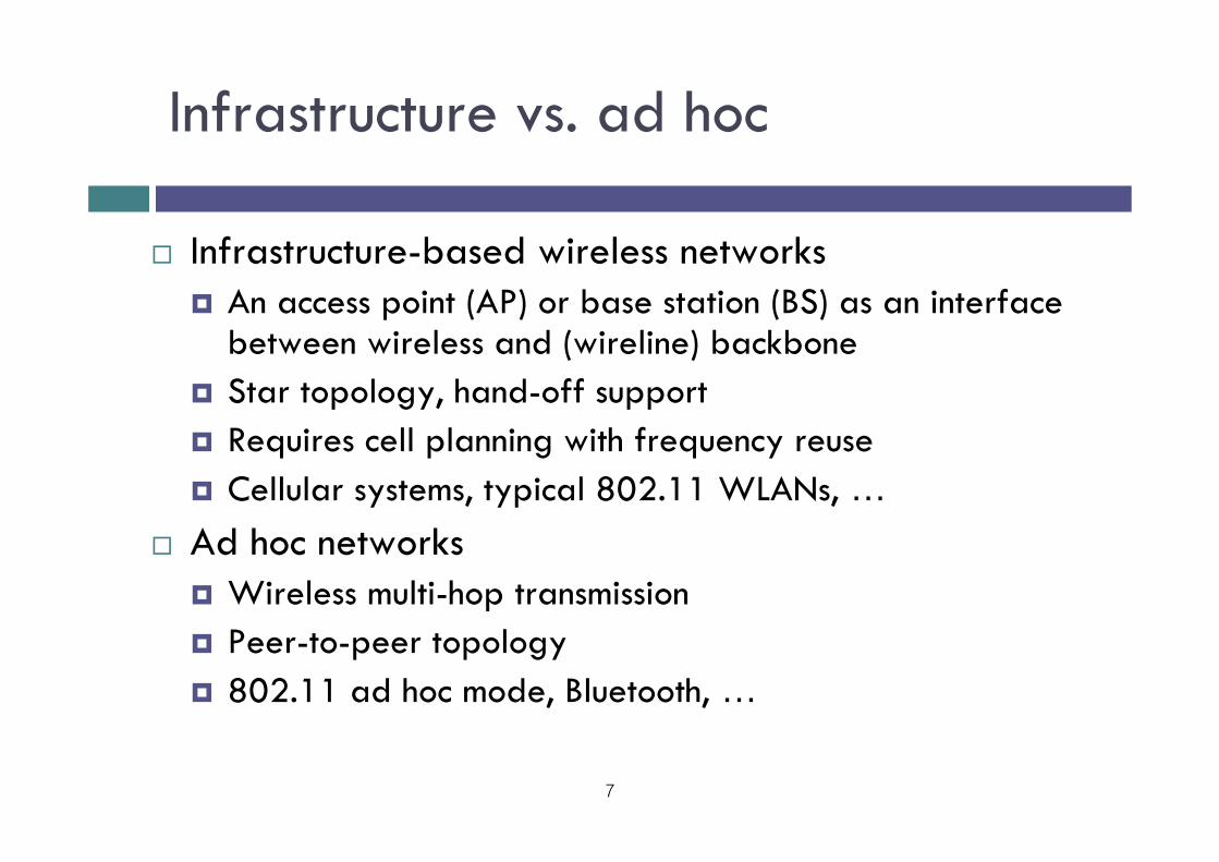
Infrastructure vs. ad hoc
Infrastructure-based wireless networksAn access point (AP) or base station (BS) as an interface between wireless and (wireline) backbone Star topology, hand-off supportRequires cell planning with frequency reuseCellular systems, typical 802.11 WLANs, …
Ad hoc networksWireless multi-hop transmissionPeer-to-peer topology802.11 ad hoc mode, Bluetooth, …
8
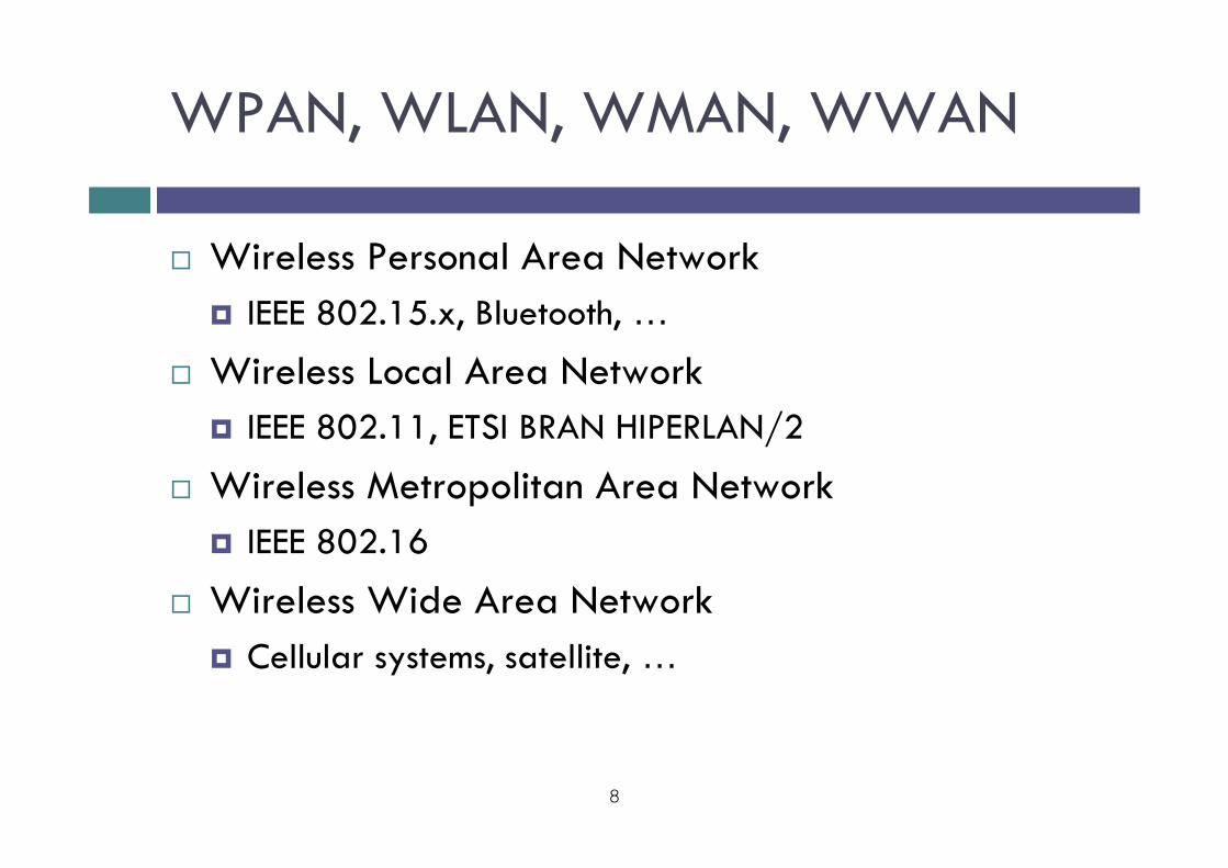
WPAN, WLAN, WMAN, WWAN
Wireless Personal Area NetworkIEEE 802.15.x, Bluetooth, …
Wireless Local Area NetworkIEEE 802.11, ETSI BRAN HIPERLAN/2
Wireless Metropolitan Area NetworkIEEE 802.16
Wireless Wide Area NetworkCellular systems, satellite, …
9
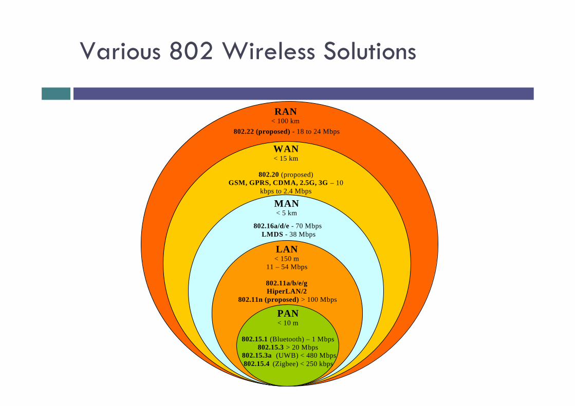
Various 802 Wireless Solutions
PAN< 10 m
802.15.1 (Bluetooth) – 1 Mbps802.15.3 > 20 Mbps
802.15.3a (UWB) < 480 Mbps802.15.4 (Zigbee) < 250 kbps
LAN< 150 m
11 – 54 Mbps
802.11a/b/e/gHiperLAN/2
802.11n (proposed) > 100 Mbps
MAN< 5 km
802.16a/d/e - 70 MbpsLMDS - 38 Mbps
WAN< 15 km
802.20 (proposed)GSM, GPRS, CDMA, 2.5G, 3G – 10
kbps to 2.4 Mbps
RAN< 100 km
802.22 (proposed) - 18 to 24 Mbps
10
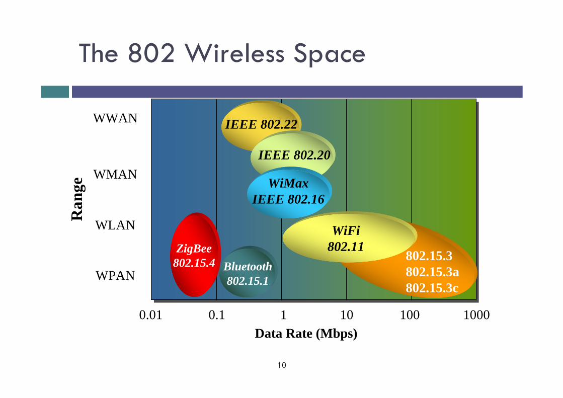
The 802 Wireless Space
Data Rate (Mbps)
Ran
ge
ZigBee802.15.4 802.15.3
802.15.3a802.15.3c
WPAN
WLAN
WMAN
WWAN
WiFi802.11
0.01 0.1 1 10 100 1000
Bluetooth802.15.1
IEEE 802.22
WiMaxIEEE 802.16
IEEE 802.20
11
Licensed vs. Unlicensed Bands
Licensed bandsOperators get the license by paying money, …800 MHz cellular, 1.9 GHz PCS, 2GHz IMT-2000 (2.1GHz)
Unlicensed bands Used without license as long as the regulatory requirements are met such as maximum transmit power level, specific modulation schemes, spectral mask, …900 MHz, 2.4GHz, 5GHz ISM bands
Different for different countries
Wireless LAN Pros and Cons
ProsFlexibility – Place your device anywhere in you houseEasy Setup – No cable, connectors.Cost – Initially higher, afterwards no cost for new wiring.
ConsSpeed – Lower compared to wired. 100Mbps can be achieved using 802.11n hardware.Radio Interference – Cordless phones, microwaves, and ham radios interfere the communicationDistance – Signal strength degrades exponentially over distanceSecurity – Radio signal broadcasts in all directions, anyone within range can tune in.
12
Networking Lab, Kyung Hee University
WLAN Architecture
InfrastructureWireless stations communicate with a Central Coordinator named as Access Point (AP)The coverage area of an AP is referred to as Basic Service Set (BSS)Coverage area of other Access Points is called Extended Service Set (ESS)
Ad-hocDistributed Coordination (Local)
Mesh NetworkA combination of Infrastructure and Ad-hocCommunication between BSS and ESS
13
Networking Lab, Kyung Hee University
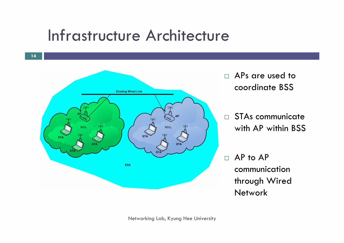
Infrastructure Architecture
APs are used to coordinate BSS
STAs communicate with AP within BSS
AP to AP communication through Wired Network
14
Networking Lab, Kyung Hee University
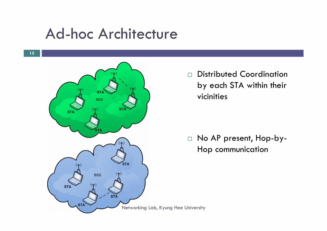
Ad-hoc Architecture
Distributed Coordination by each STA within their vicinities
No AP present, Hop-by-Hop communication
15
Networking Lab, Kyung Hee University
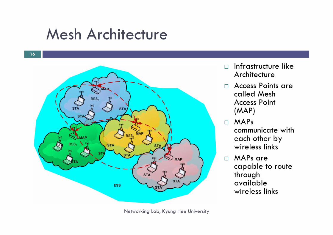
Mesh Architecture
Infrastructure like ArchitectureAccess Points are called Mesh Access Point (MAP)MAPscommunicate with each other by wireless linksMAPs are capable to route through available wireless links
16
Networking Lab, Kyung Hee University
Wireless LAN Standards
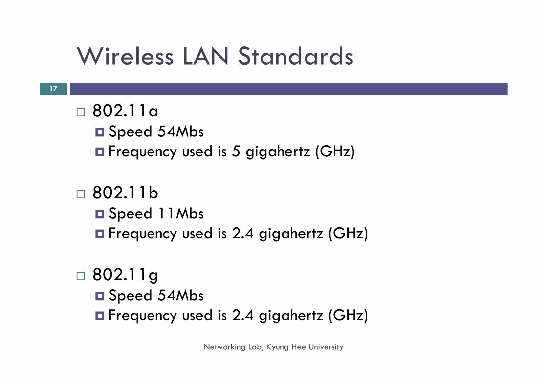
802.11aSpeed 54MbsFrequency used is 5 gigahertz (GHz)
802.11bSpeed 11MbsFrequency used is 2.4 gigahertz (GHz)
802.11gSpeed 54MbsFrequency used is 2.4 gigahertz (GHz)
17
Networking Lab, Kyung Hee University
Wireless LAN Standards (Contd.)
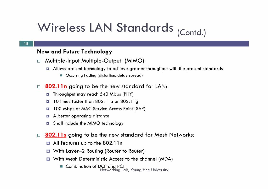
New and Future TechnologyMultiple-Input Multiple-Output (MIMO)
Allows present technology to achieve greater throughput with the present standardsOccurring Fading (distortion, delay spread)
802.11n going to be the new standard for LAN:Throughput may reach 540 Mbps (PHY)10 times faster than 802.11a or 802.11g 100 Mbps at MAC Service Access Point (SAP)A better operating distance Shall include the MIMO technology
802.11s going to be the new standard for Mesh Networks:All features up to the 802.11nWith Layer–2 Routing (Router to Router)With Mesh Deterministic Access to the channel (MDA)
Combination of DCF and PCF
18
Networking Lab, Kyung Hee University
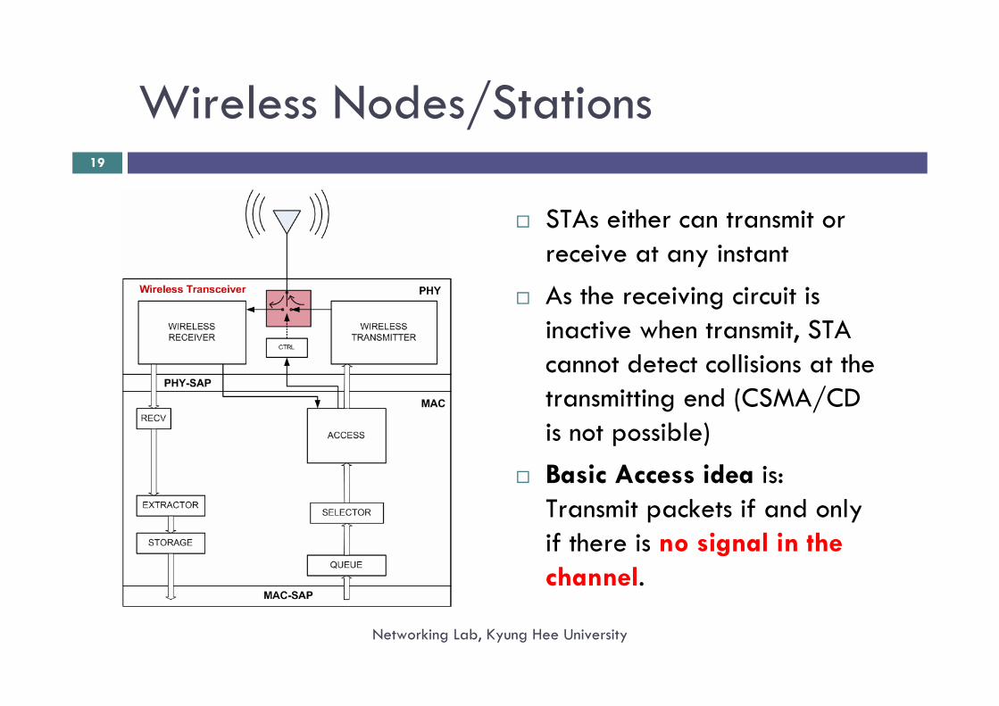
Wireless Nodes/Stations
Networking Lab, Kyung Hee University
19
STAs either can transmit or receive at any instantAs the receiving circuit is inactive when transmit, STA cannot detect collisions at the transmitting end (CSMA/CD is not possible)Basic Access idea is: Transmit packets if and only if there is no signal in the channel.
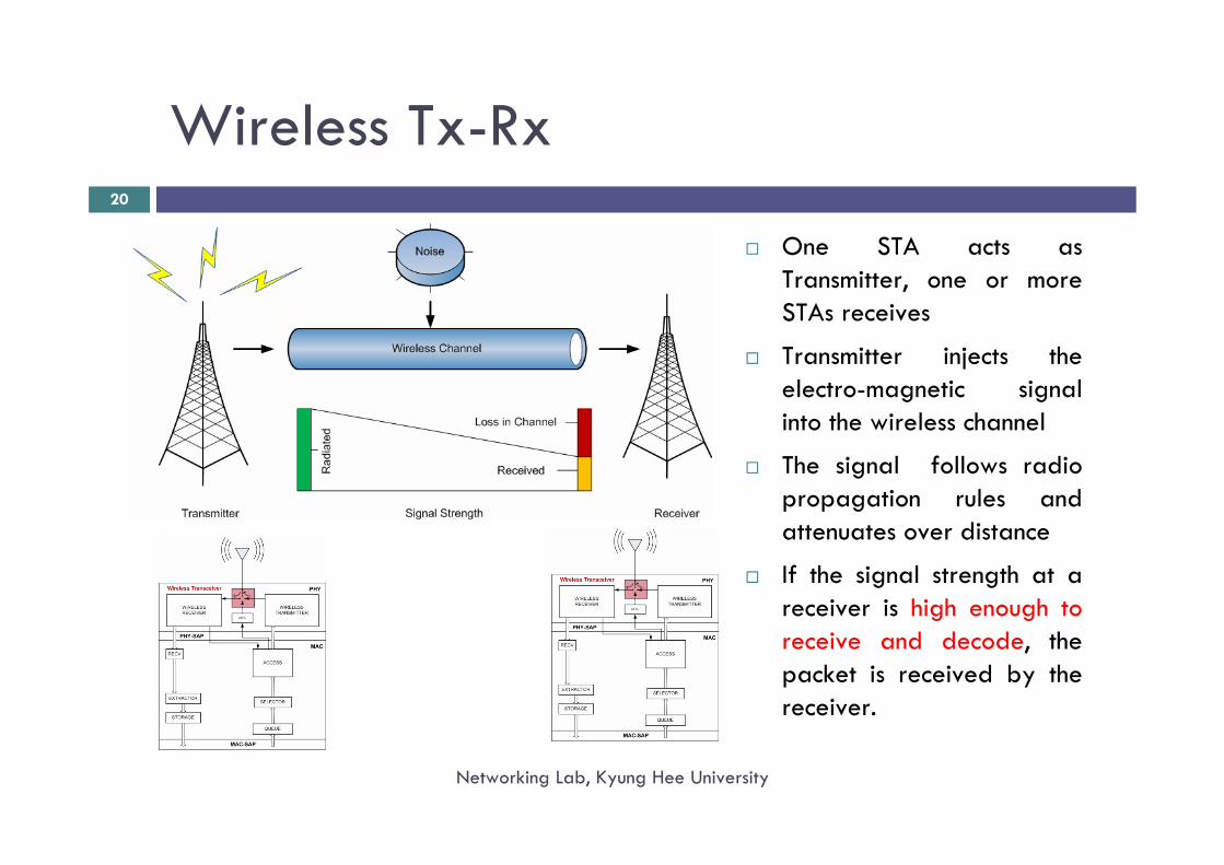
Wireless Tx-Rx
Networking Lab, Kyung Hee University
20
One STA acts as Transmitter, one or more STAs receives
Transmitter injects the electro-magnetic signal into the wireless channel
The signal follows radio propagation rules and attenuates over distance
If the signal strength at a receiver is high enough to receive and decode, the packet is received by the receiver.
Wireless Tx-Rx (Contd.)
Networking Lab, Kyung Hee University
21
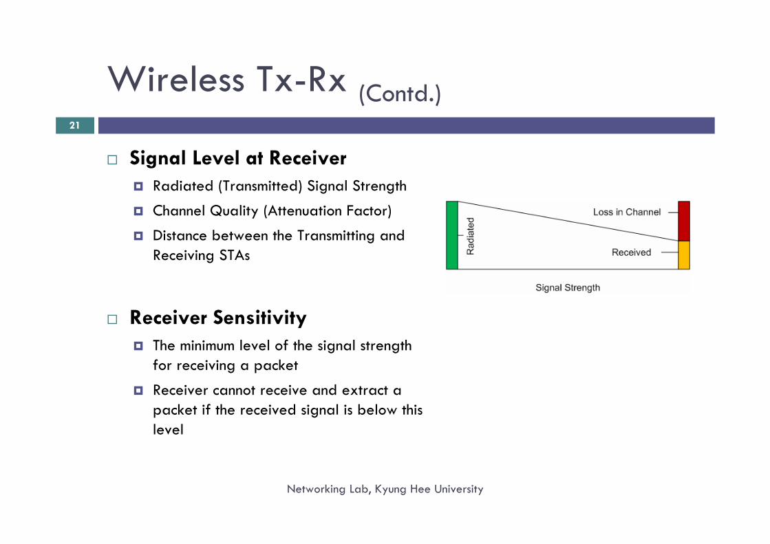
Signal Level at ReceiverRadiated (Transmitted) Signal Strength
Channel Quality (Attenuation Factor)
Distance between the Transmitting and Receiving STAs
Receiver SensitivityThe minimum level of the signal strength for receiving a packet
Receiver cannot receive and extract a packet if the received signal is below this level
Wireless Tx-Rx (Contd.)
Networking Lab, Kyung Hee University
22
Question:Is there any Transmission Range?
Answer:NOIt is better to use the term as Communication RangeThe Receiver Sensitivity and Transmission Power jointly define the Communication Range
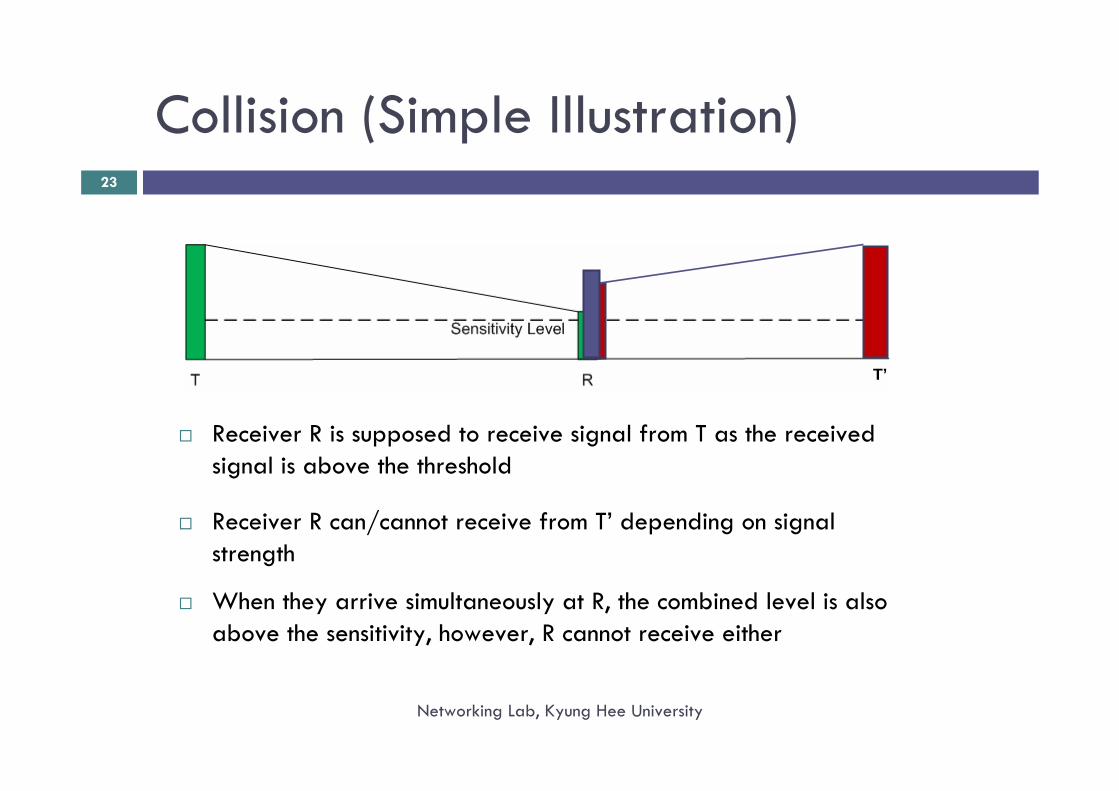
Collision (Simple Illustration)
Networking Lab, Kyung Hee University
23
Receiver R is supposed to receive signal from T as the received signal is above the threshold
Receiver R can/cannot receive from T’ depending on signal strength
When they arrive simultaneously at R, the combined level is alsoabove the sensitivity, however, R cannot receive either
T’
Media Access Problems in WLAN
Networking Lab, Kyung Hee University
24
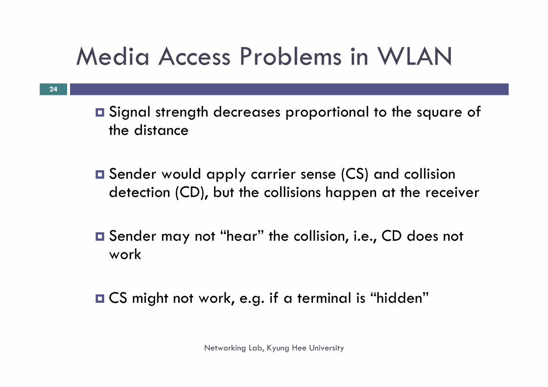
Signal strength decreases proportional to the square of the distance
Sender would apply carrier sense (CS) and collision detection (CD), but the collisions happen at the receiver
Sender may not “hear” the collision, i.e., CD does not work
CS might not work, e.g. if a terminal is “hidden”
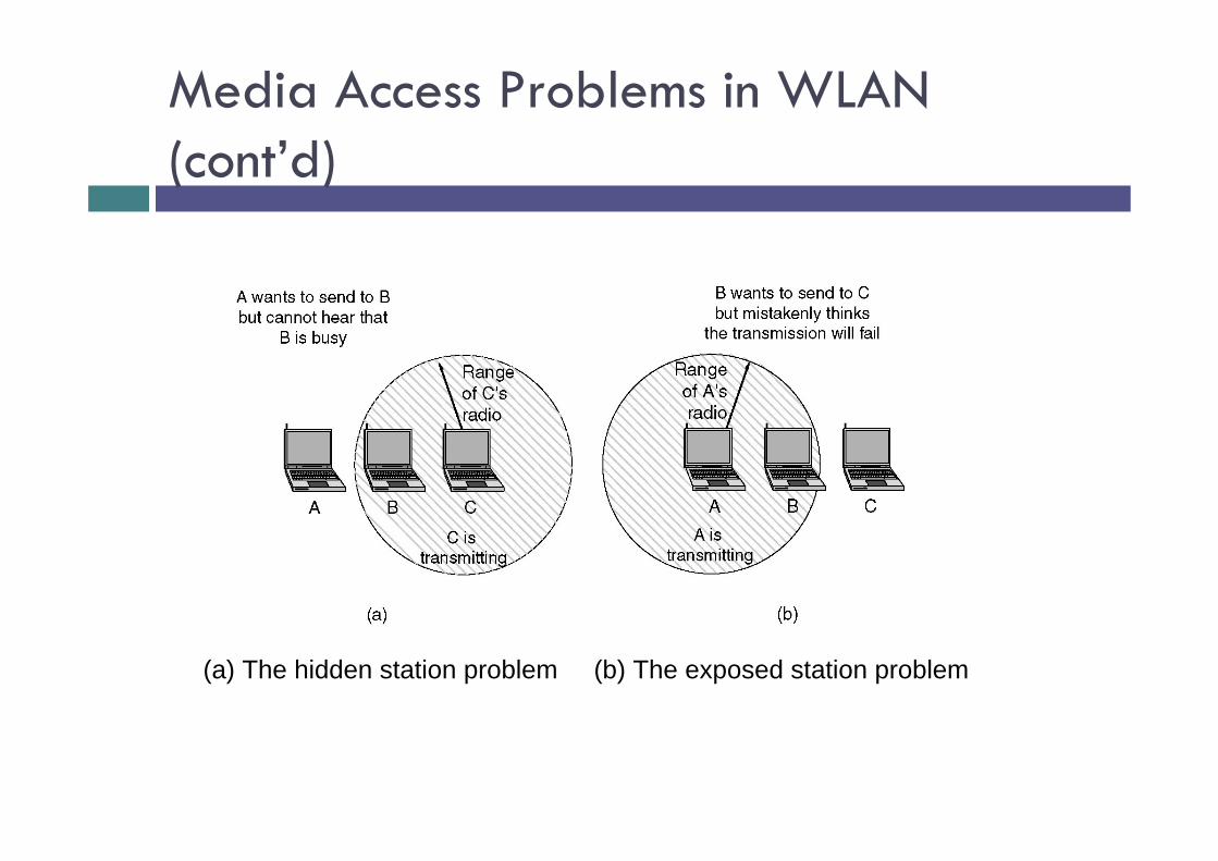
Media Access Problems in WLAN (cont’d)
(a) The hidden station problem (b) The exposed station problem
Popular Wireless MAC Protocols
Networking Lab, Kyung Hee University
26
Carrier Sense Multiple Access (CSMA)Transmit when the channel is found free (Don’t create problem to others)Collides when n (n>1)STAs access simultaneously
Carrier Sense Multiple Access with Collision Avoidance (CSMA/CA)If the channel is free, wait for some random time (Referred to as Random Backoff Period), and if the channel is still free, start transmissionDon’t create problem to others who already accessed the channelPLUS wait for some time if any other startsCollides when n (n > 1) STAs wait for same random time after channel becomes free
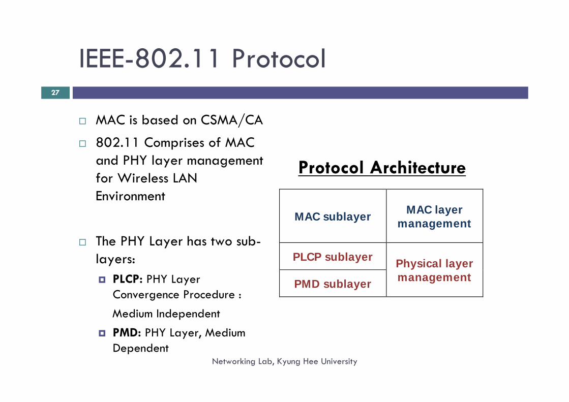
IEEE-802.11 Protocol
Networking Lab, Kyung Hee University
27
MAC is based on CSMA/CA
802.11 Comprises of MAC and PHY layer management for Wireless LAN Environment
The PHY Layer has two sub-layers:
PLCP: PHY Layer Convergence Procedure : Medium IndependentPMD: PHY Layer, Medium Dependent
MAC sublayer MAC layer management
PLCP sublayer Physical layer management PMD sublayer
Protocol Architecture
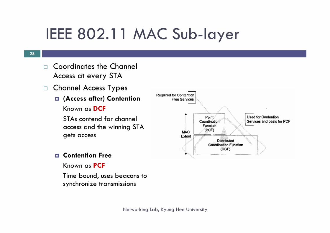
IEEE 802.11 MAC Sub-layer
Networking Lab, Kyung Hee University
28
Coordinates the Channel Access at every STAChannel Access Types
(Access after) ContentionKnown as DCFSTAs contend for channel access and the winning STA gets access
Contention FreeKnown as PCFTime bound, uses beacons to synchronize transmissions
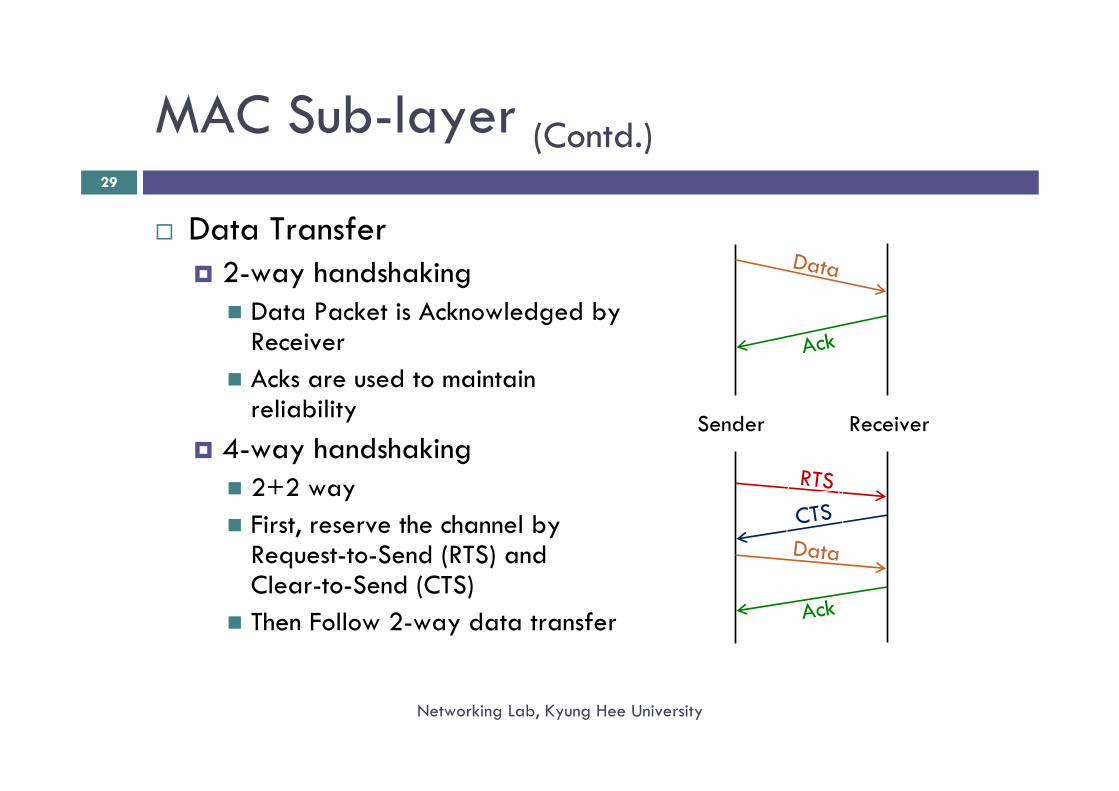
MAC Sub-layer (Contd.)
Networking Lab, Kyung Hee University
29
Data Transfer2-way handshaking
Data Packet is Acknowledged by ReceiverAcks are used to maintain reliability
4-way handshaking2+2 wayFirst, reserve the channel by Request-to-Send (RTS) and Clear-to-Send (CTS)Then Follow 2-way data transfer
Data
Ack
Data
Ack
RTS
CTS
Sender Receiver
RTS/CTS
Networking Lab, Kyung Hee University
30
If packet size > RTSThreshold (typically 500 bytes)4-way handshaking is used
Two-fold benefitChannel Reservation for long data packets, and thus, reducing collision probability by hidden and exposed terminalsLong data transmission defers until receiving STA clears; determining collisions before transmitting large packets
MAC Sub-layer (Contd.)
Networking Lab, Kyung Hee University
31
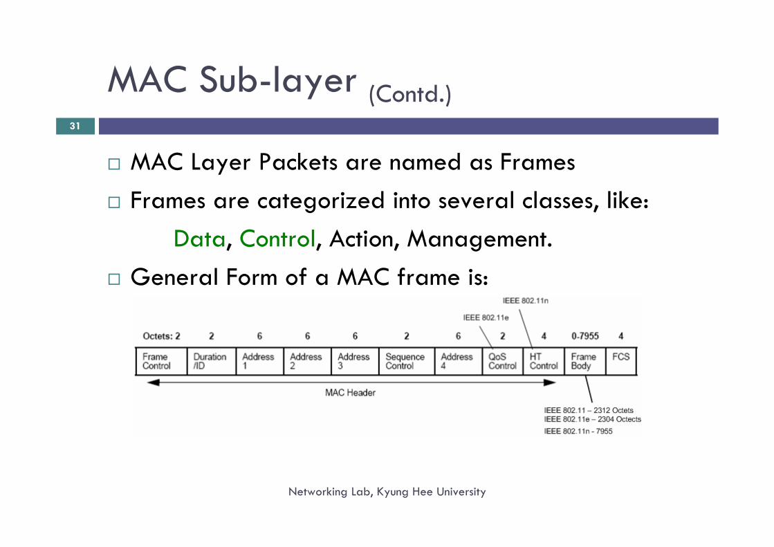
MAC Layer Packets are named as FramesFrames are categorized into several classes, like:
Data, Control, Action, Management.General Form of a MAC frame is:
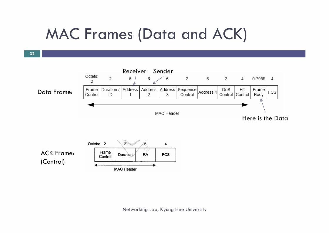
MAC Frames (Data and ACK)
Networking Lab, Kyung Hee University
32
Here is the Data
Receiver Sender
Data Frame:
ACK Frame:(Control)
32
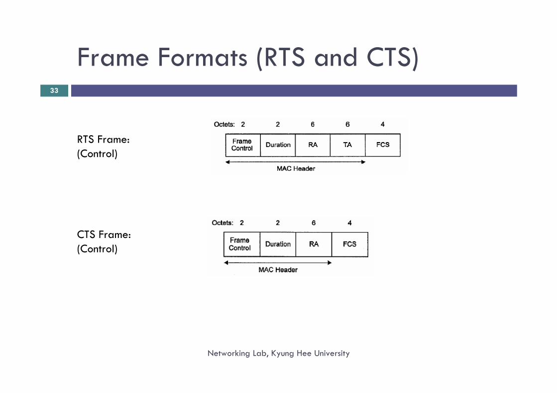
Frame Formats (RTS and CTS)
Networking Lab, Kyung Hee University
33
RTS Frame:(Control)
CTS Frame:(Control)
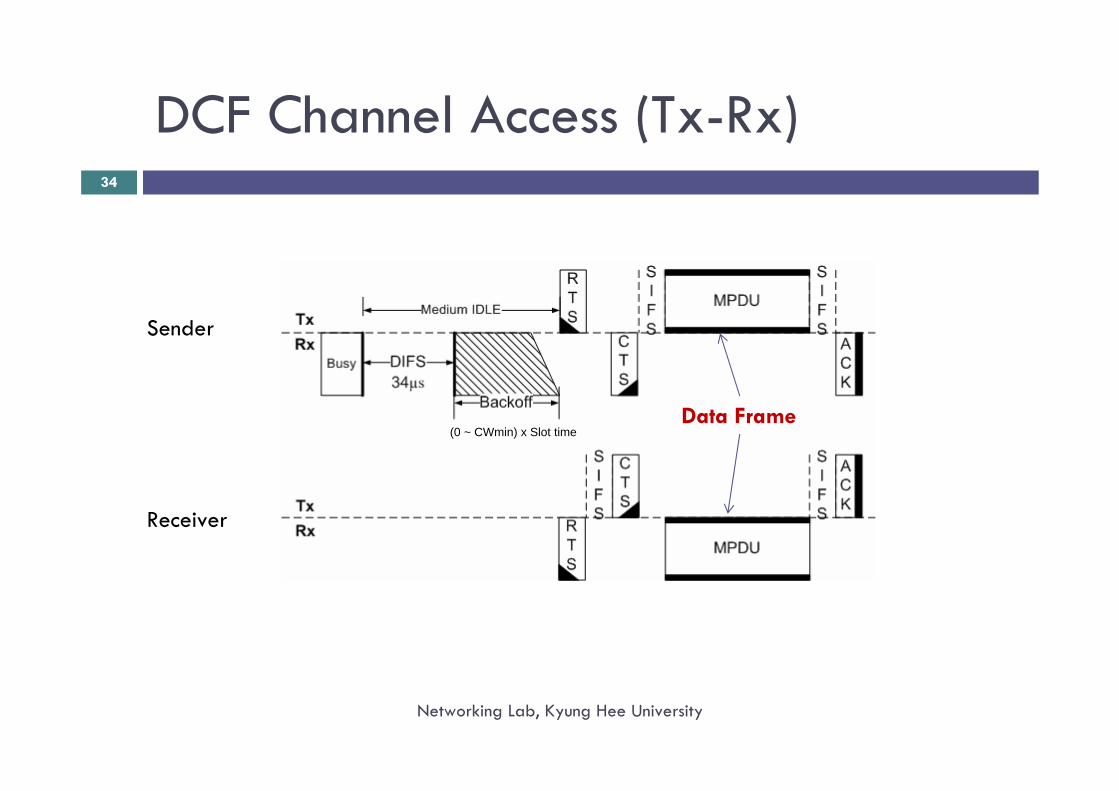
DCF Channel Access (Tx-Rx)
Networking Lab, Kyung Hee University
34
Sender
Receiver
Data Frame(0 ~ CWmin) x Slot time
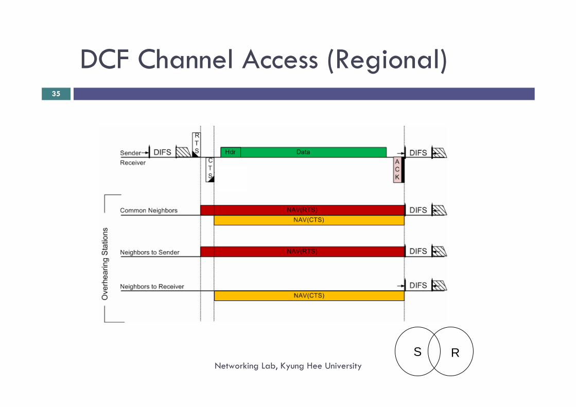
DCF Channel Access (Regional)
Networking Lab, Kyung Hee University
35
S R
Distributed Coordination Function (DCF)
Networking Lab, Kyung Hee University
36
Local Coordination using..Carrier Sensing (CS)Inter-frame Space (IFS)Adaptive Random BackoffRetransmission Scheme (Retry)
DCF - Carrier Sensing
Networking Lab, Kyung Hee University
37
Two Types of Carrier Sense mechanismPhysical Carrier Sensing
Receives 0/1 from PHY layer indicating absence or presence of carrier in the medium
Virtual Carrier SensingFrom overheard frames, STAs can find duration of current transmissionPhysical Carrier Sensing is worthless during this periodMaintains a Counter named as Network Allocation Vector (NAV) that indicates how long the medium would be occupied by other stationIf NAV > 0, the channel is busyThe NAV is decremented at each time slot and when it reaches to zero, the physical carrier sensing is applied
Inter-Frame Space (IFS)
Networking Lab, Kyung Hee University
38
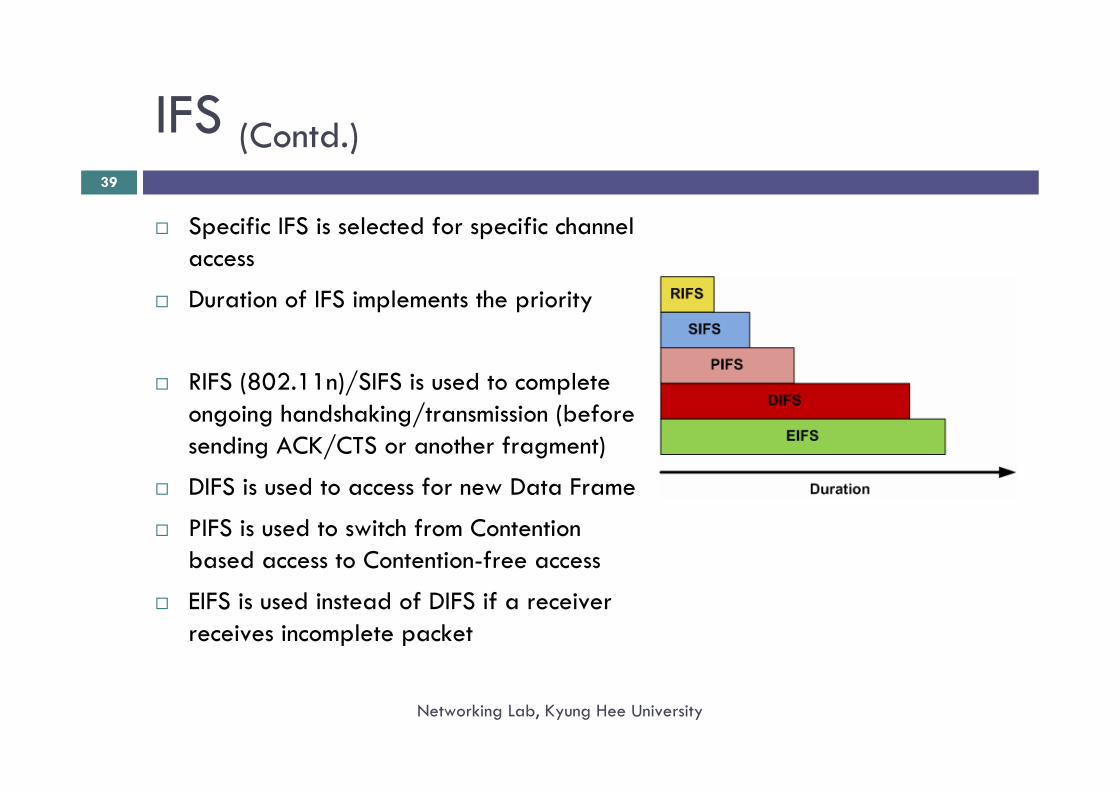
Inter-Frame Spaces are used to control the frame sequences during 2-way or 4-way handshaking
Five IFS are available:DIFS – DCF IFS; used for accessing channel for Data FramesSIFS – Shortest IFS; used to continue with obtained accessPIFS – PCF IFS; entry point for PCF mode from DCFEIFS – Extended IFS; for receivers received erroneous /incomplete packet RIFS – Reduced (S)IFS (802.11n); for High Throughput (HT)
IFS (Contd.)
Networking Lab, Kyung Hee University
39
Specific IFS is selected for specific channel access
Duration of IFS implements the priority
RIFS (802.11n)/SIFS is used to complete ongoing handshaking/transmission (before sending ACK/CTS or another fragment)
DIFS is used to access for new Data Frame
PIFS is used to switch from Contention based access to Contention-free access
EIFS is used instead of DIFS if a receiver receives incomplete packet
Random Backoff
Networking Lab, Kyung Hee University
40
CSMA/CA uses Random Backoff in order to prevent simultaneous access by two transmitters in order to avoid collision
The random backoff period is determined by a chosen random number from a pool of numbers named as Contention Window (CW)
STAs uniformly pick a number r from range [0,CW) and determines the Backoff period using:
Backoff Period = r x Slot time
DCF uses Residual Backoff; that means, if a backoff value is chosen, it is continued for consecutive busy/free medium until it reaches to zero and the STA gets access to the channel
Adaptive Random Backoff
Networking Lab, Kyung Hee University
41
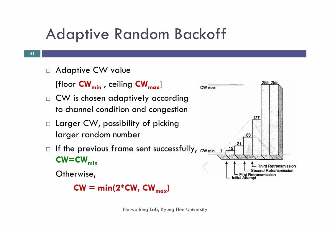
Adaptive CW value[floor CWmin , ceiling CWmax]CW is chosen adaptively according to channel condition and congestionLarger CW, possibility of picking larger random numberIf the previous frame sent successfully, CW=CWmin
Otherwise,CW = min(2*CW, CWmax)
Retransmission
Networking Lab, Kyung Hee University
42
Wireless links are not stable and error prone
DCF retransmits up to certain limit(s) for unsuccessful transmissions
How DCF detects unsuccessful transmission?If the sender is unable to receive ACK frame
Why the Sender may not receive ACK?The receiver didn’t send it (the data frame is not successfully received at the receiver)The receiver sent the ACK frame, but it collided at sender or channel condition distorted the ACK frame
Retransmission (Contd.)
Networking Lab, Kyung Hee University
43
DCF retransmits a data frame up to4 times (short retry limit) when no RTS/CTS is required7 times (long retry limit) when RTS/CTS is required
Each retransmission follows same DCF cycle
Entire data frame is resent (large overhead for long data frames)
DCF performance
Networking Lab, Kyung Hee University
44
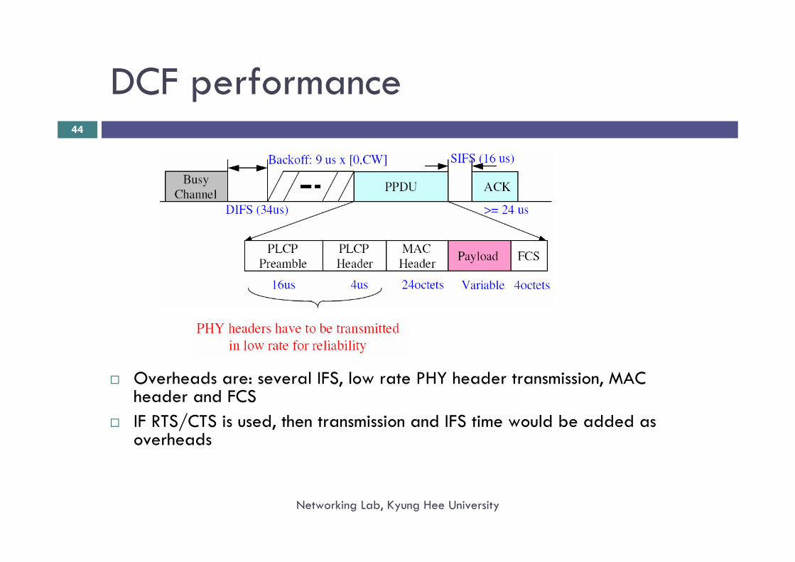
Overheads are: several IFS, low rate PHY header transmission, MAC header and FCSIF RTS/CTS is used, then transmission and IFS time would be added as overheads
DCF performance (Contd.)
Networking Lab, Kyung Hee University
45
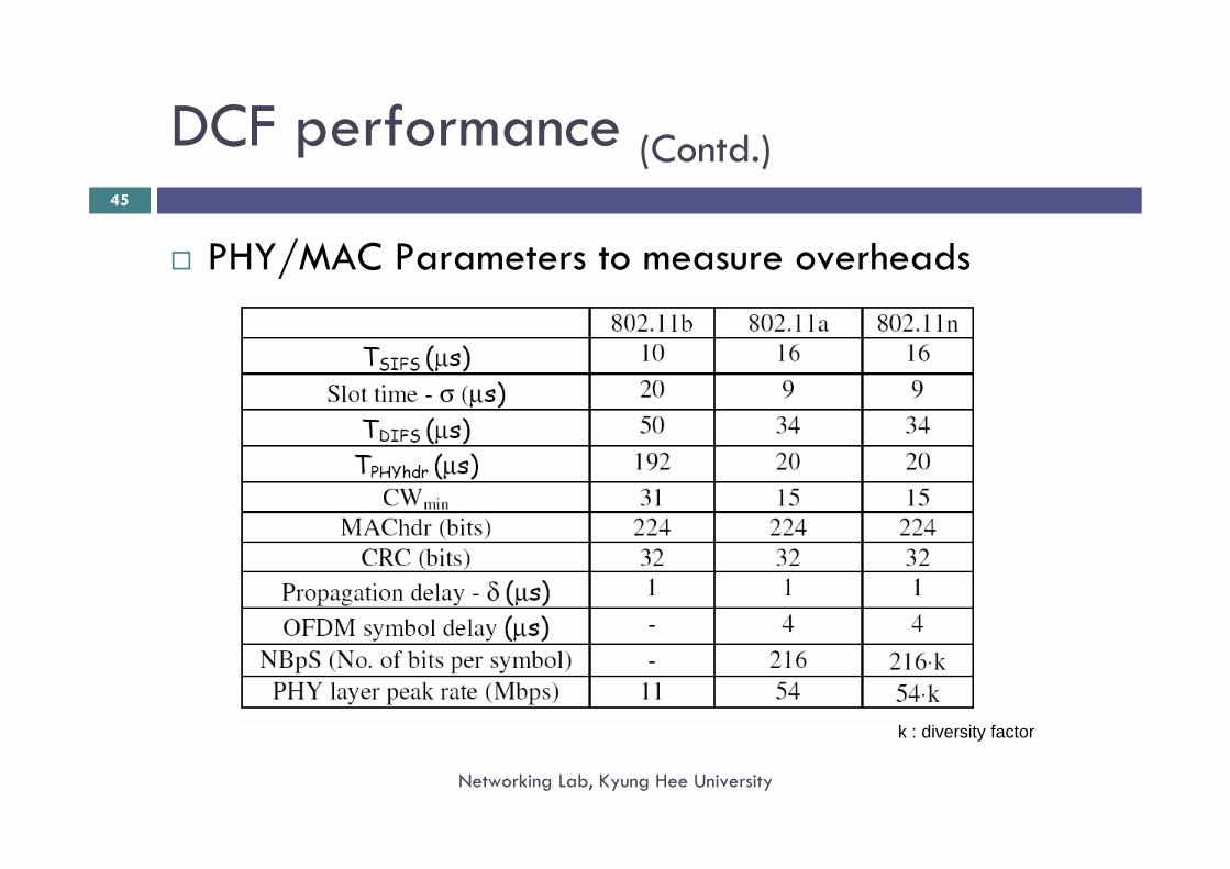
PHY/MAC Parameters to measure overheads
k : diversity factor
DCF performance (Contd.)
Networking Lab, Kyung Hee University
46
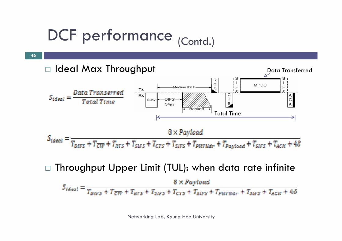
Ideal Max Throughput
Throughput Upper Limit (TUL): when data rate infinite
Data Transferred
Total Time
DCF performance (Contd.)
Networking Lab, Kyung Hee University
47
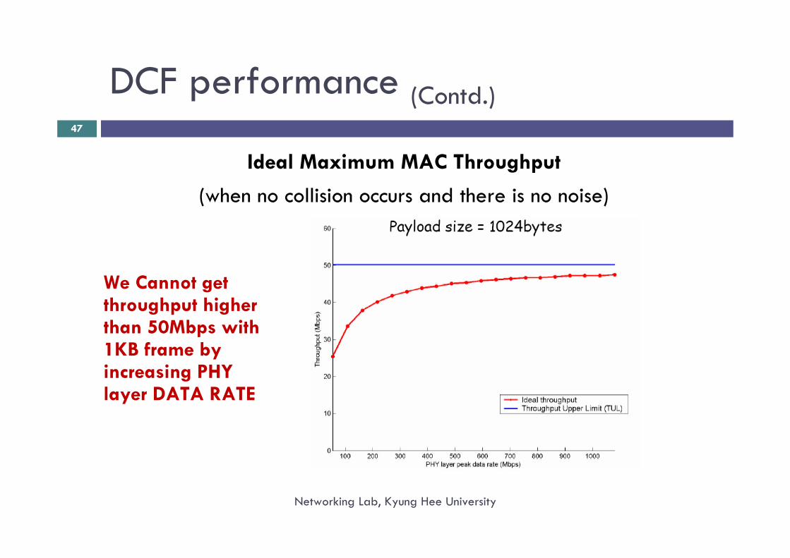
Ideal Maximum MAC Throughput
(when no collision occurs and there is no noise)
We Cannot get throughput higher than 50Mbps with 1KB frame by increasing PHY layer DATA RATE
How to improve DCF performance?
Networking Lab, Kyung Hee University
48
Send MAX data packets once a STA gets access
Use a Reduced IFS when multiple data packets are sent
Why we cannot change DIFS and other timing?
• To cooperate with Legacy 802.11 devices
What is the consequence of sending multiple frames in single access?
• Neighbors of transmitter and receiver would experience large NAV
• For each unsuccessful transmissions, if same aggregated frame isretransmitted, it would create a large overhead
Frame Aggregation (802.11n)
Networking Lab, Kyung Hee University
49
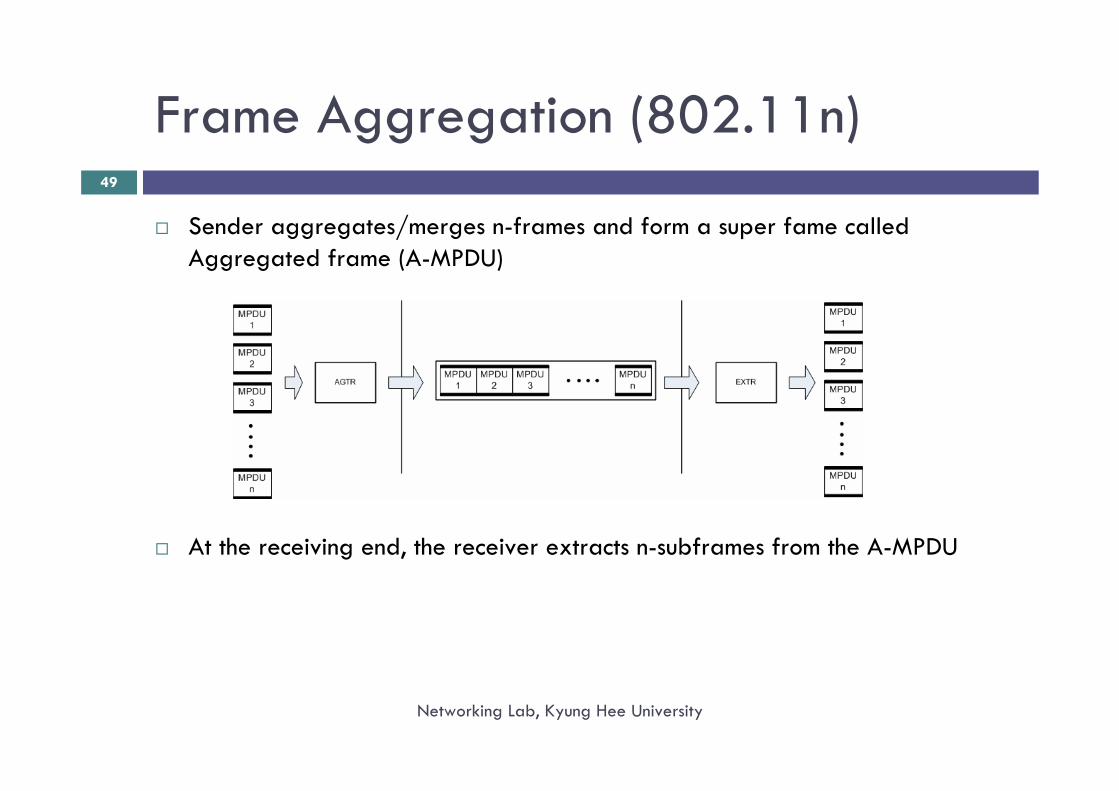
Sender aggregates/merges n-frames and form a super fame called Aggregated frame (A-MPDU)
At the receiving end, the receiver extracts n-subframes from the A-MPDU
Frame Aggregation (FA) (Contd.)
Networking Lab, Kyung Hee University
50
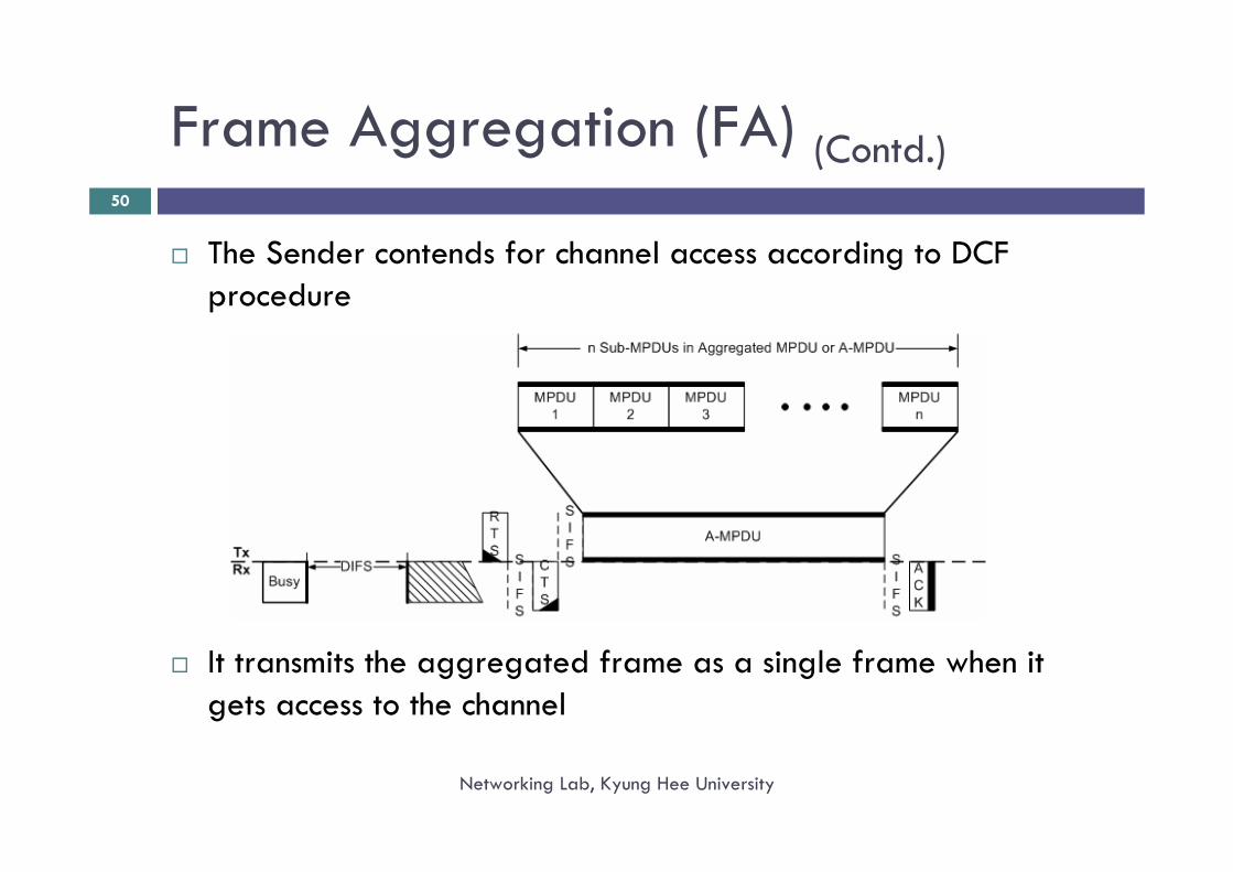
The Sender contends for channel access according to DCF procedure
It transmits the aggregated frame as a single frame when it gets access to the channel
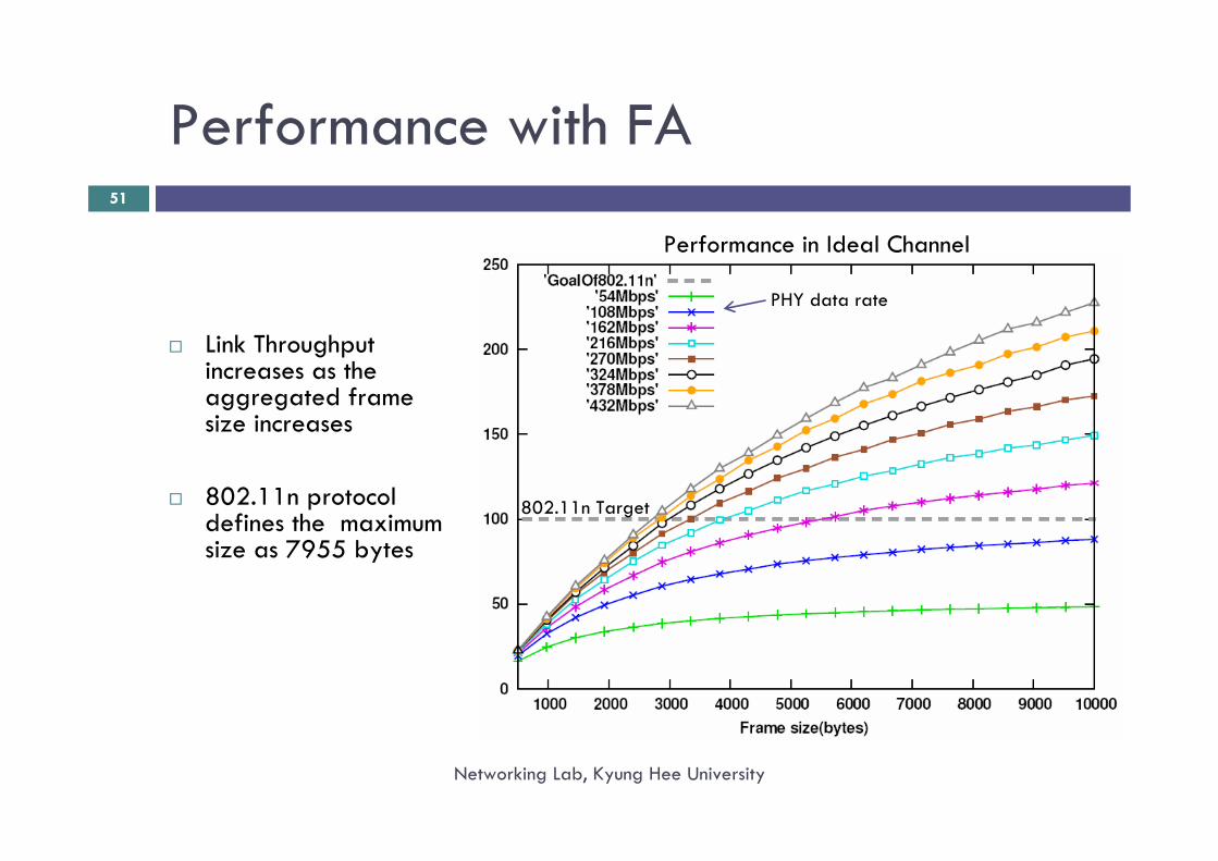
Performance with FA
Networking Lab, Kyung Hee University
51
Link Throughput increases as the aggregated frame size increases
802.11n protocol defines the maximum size as 7955 bytes
802.11n Target
PHY data rate
Performance in Ideal Channel
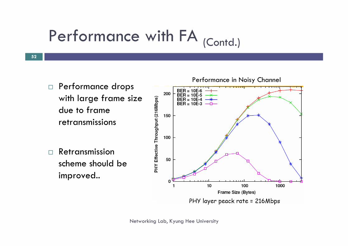
Performance with FA (Contd.)
Networking Lab, Kyung Hee University
52
Performance drops with large frame size due to frame retransmissions
Retransmission scheme should be improved..
Performance in Noisy Channel
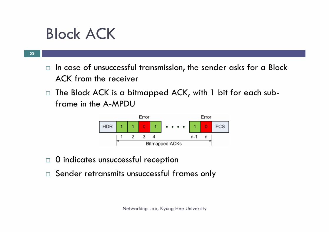
Block ACK
Networking Lab, Kyung Hee University
53
In case of unsuccessful transmission, the sender asks for a Block ACK from the receiverThe Block ACK is a bitmapped ACK, with 1 bit for each sub-frame in the A-MPDU
0 indicates unsuccessful receptionSender retransmits unsuccessful frames only
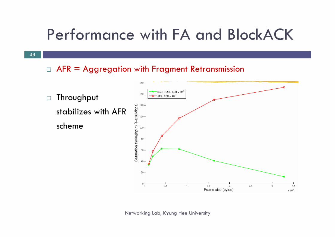
Performance with FA and BlockACK
Networking Lab, Kyung Hee University
54
AFR = Aggregation with Fragment Retransmission
Throughputstabilizes with AFRscheme
Point Coordination Function (PCF)
Networking Lab, Kyung Hee University
55
To provide time bounded service.Requires an access point.Access point polls each station during contention free period (CFP : started by beacon)Becomes an overhead during light load
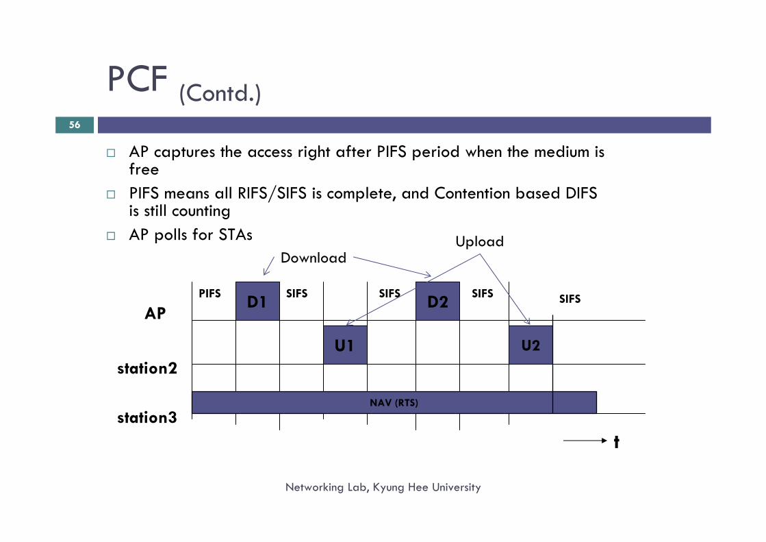
PCF (Contd.)
Networking Lab, Kyung Hee University
56
AP captures the access right after PIFS period when the medium is freePIFS means all RIFS/SIFS is complete, and Contention based DIFS is still countingAP polls for STAs
D1AP
station2
station3t
PIFS SIFS SIFS
U1
D2SIFS
U2
SIFS
NAV (RTS)
DownloadUpload
Networking Lab, Kyung Hee University
57
A closer look to the Physical Layer Properties and Interference
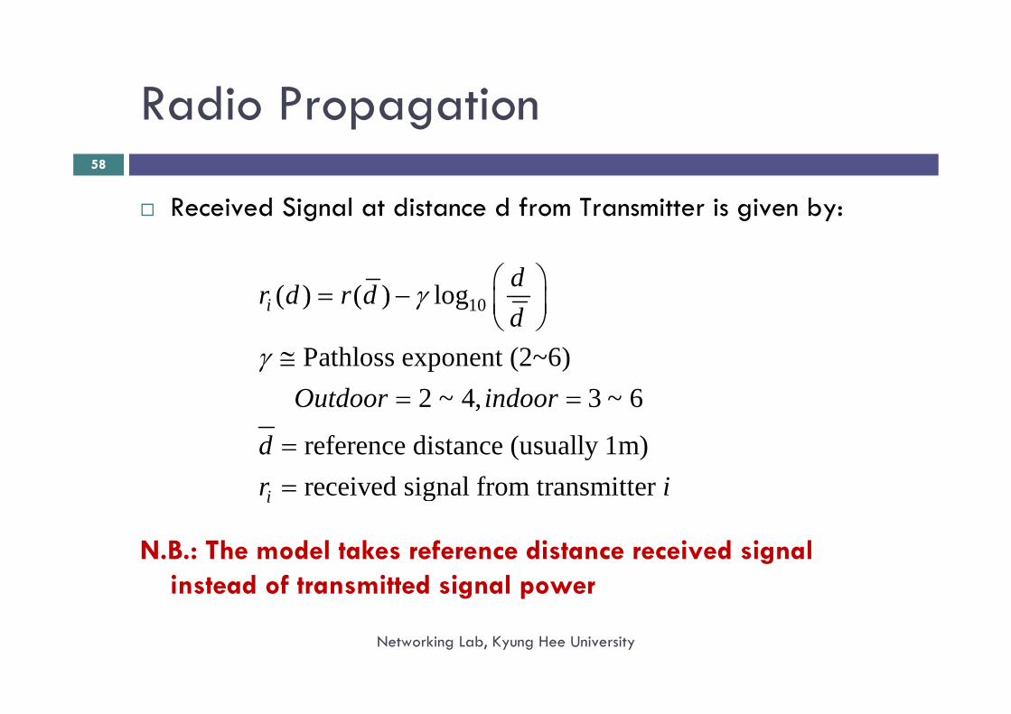
Radio Propagation
Networking Lab, Kyung Hee University
58
Received Signal at distance d from Transmitter is given by:
N.B.: The model takes reference distance received signal instead of transmitted signal power
10( ) ( ) log
Pathloss exponent (2~6)2 ~ 4, 3 ~ 6
reference distance (usually 1m)received signal from transmitter
i
i
dr d r dd
Outdoor indoor
dr i
γ
γ
⎛ ⎞= − ⎜ ⎟⎝ ⎠
≅= =
==
Receiver Sensitivity and Distance
Networking Lab, Kyung Hee University
59
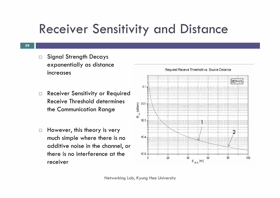
Signal Strength Decays exponentially as distance increases
Receiver Sensitivity or Required Receive Threshold determines the Communication Range
However, this theory is very much simple where there is no additive noise in the channel, or there is no interference at the receiver
1
2
Misconceptions (1)
Networking Lab, Kyung Hee University
60
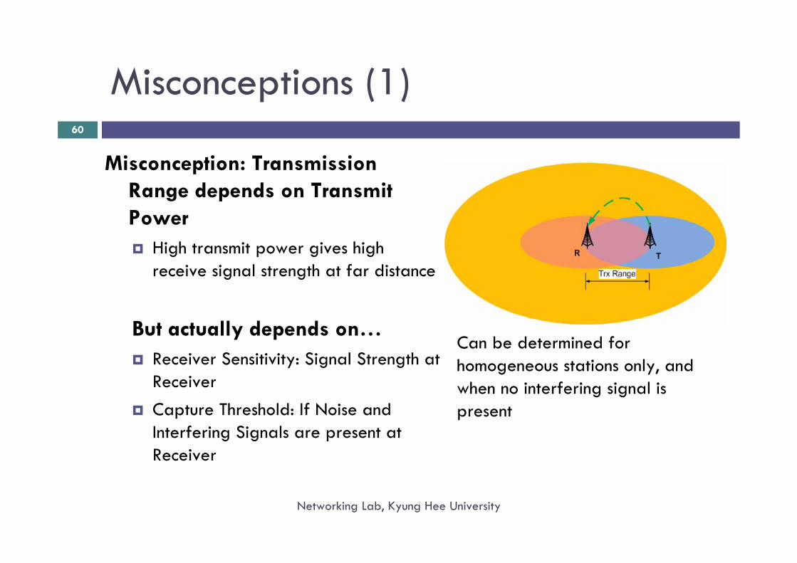
Misconception: Transmission Range depends on Transmit Power
High transmit power gives high receive signal strength at far distance
But actually depends on…Receiver Sensitivity: Signal Strength at ReceiverCapture Threshold: If Noise and Interfering Signals are present at Receiver
Can be determined for homogeneous stations only, and when no interfering signal is present
Received Signal Capturing
Networking Lab, Kyung Hee University
61
In practice, wireless channel state varies over time, and it consists of a number of noise sources that add noise
Transmitted signals from other STAs are also added with intended signal
Capture means Extracting information from received signal from superposed received signal having noise and signals from other STAs(completely depends on receiver circuitry)
Capture Threshold (Receiving Circuitry Property): The minimum required ratio of intended signal to noise and interference at which the receiver can capture intended signal
Received Signal Capturing (Contd.)
Networking Lab, Kyung Hee University
62
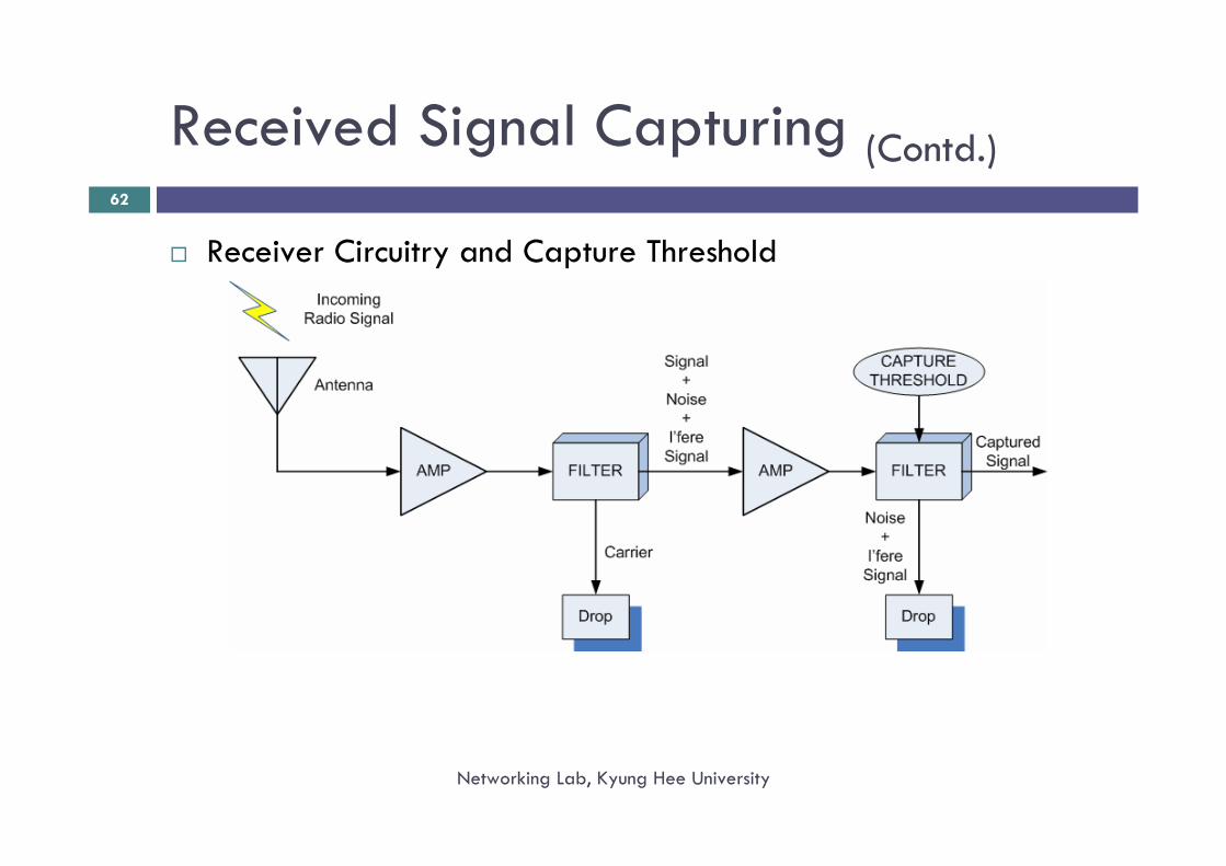
Receiver Circuitry and Capture Threshold
Received Signal Capturing (Contd.)
Networking Lab, Kyung Hee University
63
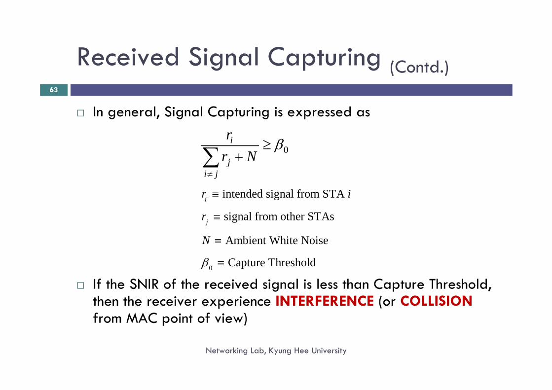
In general, Signal Capturing is expressed as
If the SNIR of the received signal is less than Capture Threshold, then the receiver experience INTERFERENCE (or COLLISIONfrom MAC point of view)
0
0
intended signal from STA
signal from other STAs
Ambient White Noise
Capture Threshold
i
j
i
ji j
r i
r
N
rr N
β
β
≠
≡
≡
≡
≡
≥+∑
Misconceptions (2):
Networking Lab, Kyung Hee University
64
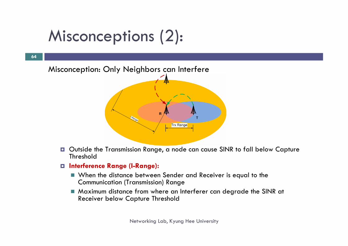
Misconception: Only Neighbors can Interfere
Outside the Transmission Range, a node can cause SINR to fall below Capture ThresholdInterference Range (I-Range):
When the distance between Sender and Receiver is equal to the Communication (Transmission) RangeMaximum distance from where an Interferer can degrade the SINR at Receiver below Capture Threshold
Simple Interference Model
Networking Lab, Kyung Hee University
65
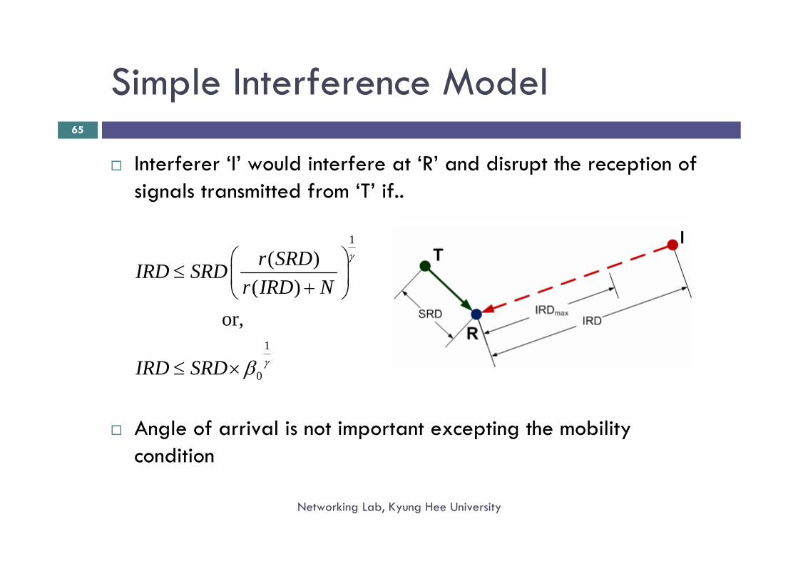
Interferer ‘I’ would interfere at ‘R’ and disrupt the reception of signals transmitted from ‘T’ if..
Angle of arrival is not important excepting the mobility condition
1
1
0
( )( )
or,
r SRDIRD SRDr IRD N
IRD SRD
γ
γβ
⎛ ⎞≤ ⎜ ⎟+⎝ ⎠
≤ ×
Which STAs can Interfere?
Networking Lab, Kyung Hee University
66
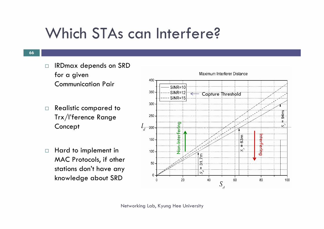
IRDmax depends on SRD for a given Communication Pair
Realistic compared to Trx/I’ference Range Concept
Hard to implement in MAC Protocols, if other stations don’t have any knowledge about SRD
Capture Threshold
Non
-Inte
rfer
ing
Interfering
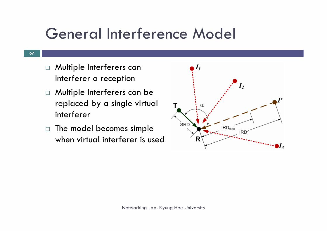
General Interference Model
Networking Lab, Kyung Hee University
67
Multiple Interferers can interferer a receptionMultiple Interferers can be replaced by a single virtual interfererThe model becomes simple when virtual interferer is used
IEEE 802.11 Interference Handling
Networking Lab, Kyung Hee University
68
IEEE 802.11 protocol avoids interference/collisions by means of Carrier Sensing
A Carrier Sense Threshold (CS Threshold) is used that defines the Interference Range (I-Range), where
CS Threshold < Receiver Sensitivity
Strength:Before transmitting, each STA can check whether it shall I’fere other communication or not
Weakness:Fixed Interference Range: Unnecessary blocking of a large number of nodes when SRD is smaller than Trans. RangeLower Aggregated Throughput
Challenge
Networking Lab, Kyung Hee University
69
Enhancement of the DCF protocol for Spatial Reuse of the Channel by..
using appropriate (or as close as possible) Interference Ranges, and,reducing number of blocking STAs during an ongoing transmission