Embed Size (px)
DESCRIPTION
Introduction to Welding.ppt
Citation preview
INTRODUCTION TO WELDING

DEFINITION
Welding is a fabrication process is defined as an operation by which two (or) more parts are united by means of heat or pressure in such a way that there is continuity of the nature of the material between these parts to be welded and forms a weld. A filler material, the melting temperature of which is of the same as that of the parent material, may or may not be used.
Welding is one of the important and versatile means of fabrication available in industry. Welding is used to join all types of materials including plastics, ferrous and non-ferrous alloys etc. Many of the high temperature metals and super alloys and fabricated processes used in industries are Gas Welding, Arc welding and Resistance welding.”
“HEATHEAT” - Primary requirement for welding, and, medium of classification of welding processes
CONTENTSCONTENTS 11 Welding Process & types of Welding Process & types of
weldingwelding 22 Welding EquipmentWelding Equipment 33 Weld DesignWeld Design 44 Weld DefectsWeld Defects 55 Distortion & its controlDistortion & its control 66 Inspection & Non-Inspection & Non-
destructive testing of weldsdestructive testing of welds 77 Special Welding techniques Special Welding techniques
88 WPS, PQR and Welder WPS, PQR and Welder qualificationsqualifications

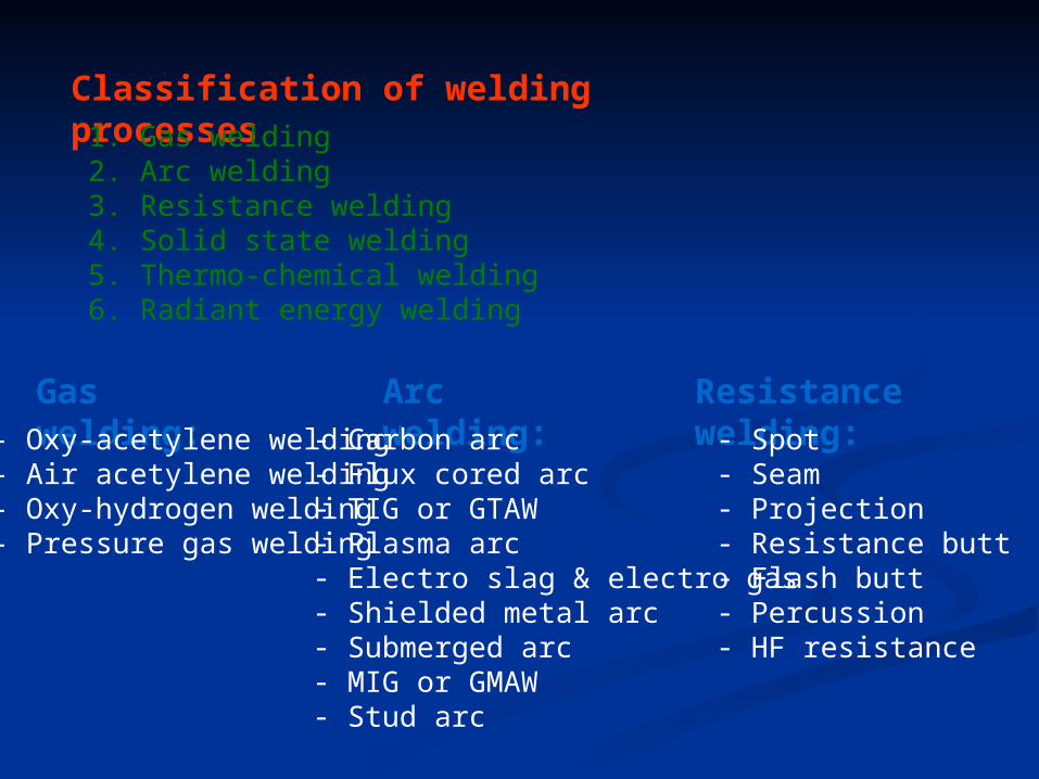
Classification of welding processes1. Gas welding2. Arc welding3. Resistance welding4. Solid state welding5. Thermo-chemical welding6. Radiant energy welding
Gas welding:- Oxy-acetylene welding- Air acetylene welding- Oxy-hydrogen welding- Pressure gas welding
Arc welding:- Carbon arc- Flux cored arc- TIG or GTAW- Plasma arc- Electro slag & electro gas- Shielded metal arc- Submerged arc- MIG or GMAW- Stud arc
Resistance welding:- Spot- Seam- Projection- Resistance butt- Flash butt- Percussion- HF resistance
Solid state welding:
- Cold welding- Explosive welding- Friction welding- Roll welding- Diffusion welding- Forge welding- Hot-pressure welding- Ultrasonic welding
Thermo-chemical:
- Thermit welding- Atomic hydrogen welding
Radiant energy welding:
- Electron beam welding- Laser beam welding
Advantages of welding- A good weld is as strong as the base metal- Low cost of general-welding equipment (economical)- Portable equipment- Permits freedom in design- Lighter, smoother structure- Both similar & dissimilar metals can be joined- Simplicity in design, ease of modification/additions- Mechanization of welding processes
Disadvantages of welding
- Harmful light radiations, fumes, splatter etc.- Residual stresses & distortion, due to high heat- Change in metallurgical properties of base metal- Jigs n fixtures required to hold job- Edge preparation required- Skilled labour- High standards of testing and inspection, etc.
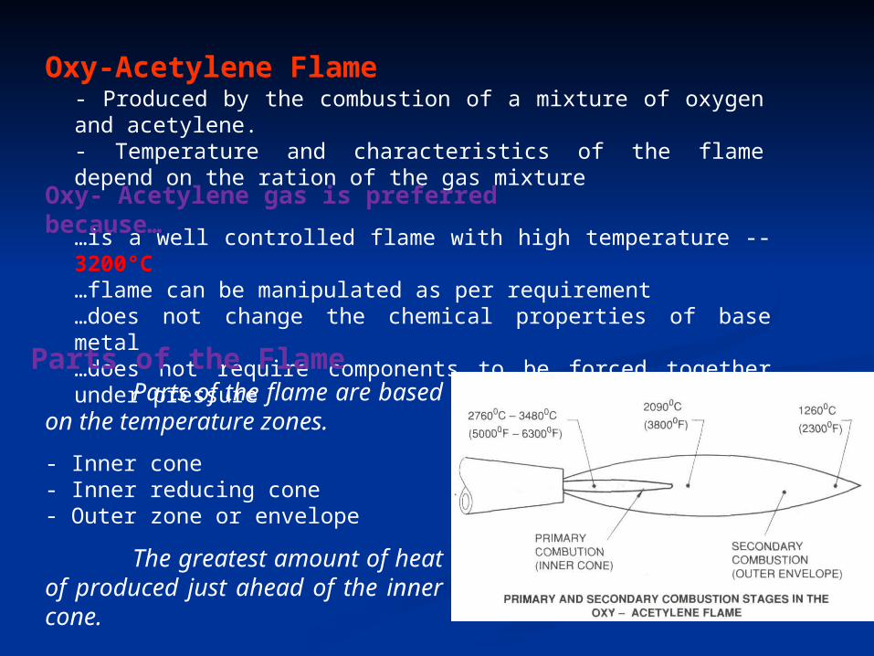
Oxy-Acetylene Flame
…is a well controlled flame with high temperature -- 3200°C…flame can be manipulated as per requirement…does not change the chemical properties of base metal…does not require components to be forced together under pressure
Parts of the FlameParts of the flame are based on
the temperature zones.
- Inner cone- Inner reducing cone- Outer zone or envelope
The greatest amount of heat of produced just ahead of the inner cone.
Oxy- Acetylene gas is preferred because…
- Produced by the combustion of a mixture of oxygen and acetylene.- Temperature and characteristics of the flame depend on the ration of the gas mixture
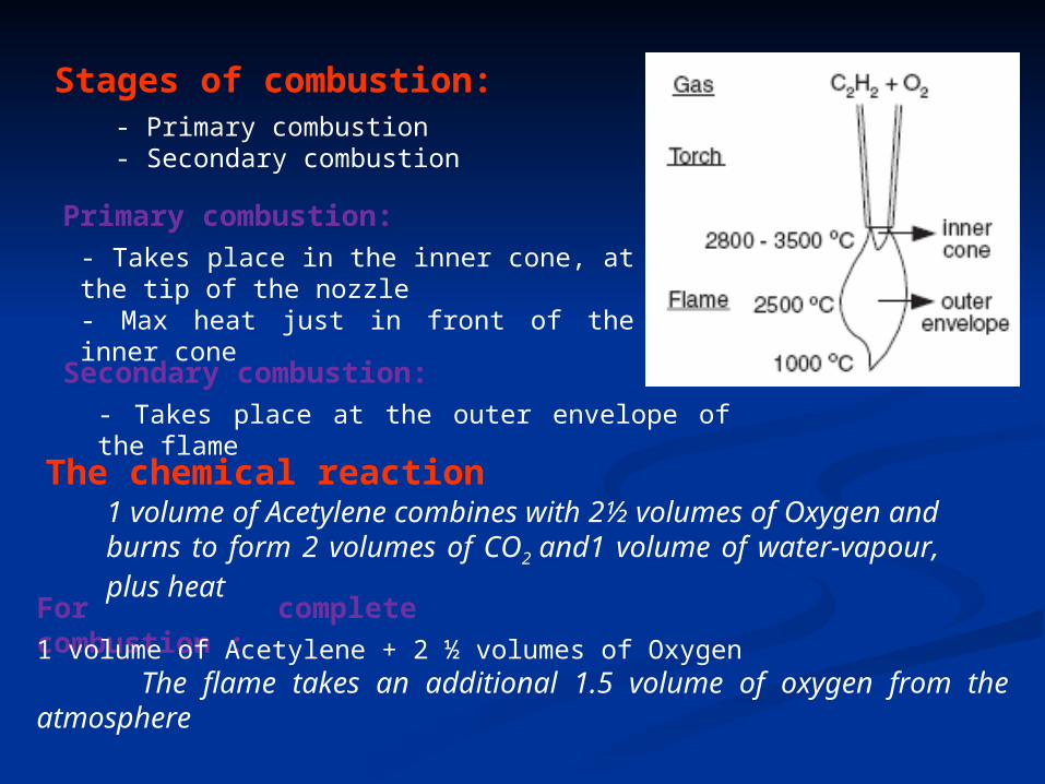
Primary combustion:
Stages of combustion:- Primary combustion- Secondary combustion
- Takes place in the inner cone, at the tip of the nozzle- Max heat just in front of the inner cone
Secondary combustion:
- Takes place at the outer envelope of the flame
The chemical reaction1 volume of Acetylene combines with 2½ volumes of Oxygen and burns to form 2 volumes of CO2
and1 volume of water-vapour, plus heat
For complete combustion :
1 volume of Acetylene + 2 ½ volumes of OxygenThe flame takes an additional 1.5 volume of oxygen from the atmosphere
Types of Flame:- Neutral flame- Oxidising Flame- Carburizing or Reducing flame
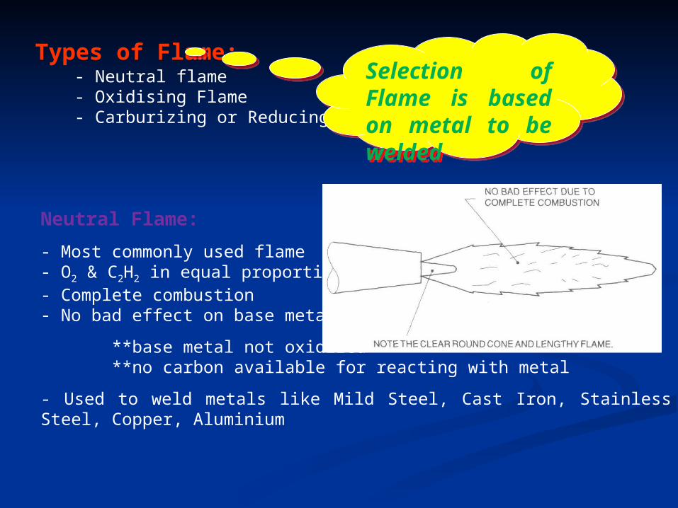
Neutral Flame:
- Most commonly used flame- O2 & C2H2 in equal proportion- Complete combustion- No bad effect on base metal,
**base metal not oxidized **no carbon available for reacting with metal
- Used to weld metals like Mild Steel, Cast Iron, Stainless Steel, Copper, Aluminium
Selection of Flame is based on metal to be welded
Selection of Flame is based on metal to be welded
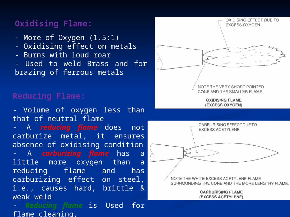
Oxidising Flame:
- More of Oxygen (1.5:1)- Oxidising effect on metals- Burns with loud roar- Used to weld Brass and for brazing of ferrous metals
Reducing Flame:
- Volume of oxygen less than that of neutral flame- A reducing flame does not carburize metal, it ensures absence of oxidising condition- A carburizing flame has a little more oxygen than a reducing flame and has carburizing effect on steel, i.e., causes hard, brittle & weak weld- Reducing flame is Used for flame cleaning,
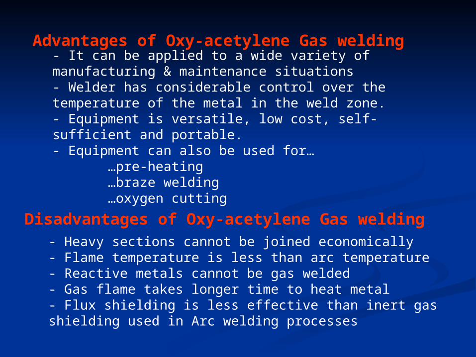
Advantages of Oxy-acetylene Gas welding- It can be applied to a wide variety of manufacturing & maintenance situations- Welder has considerable control over the temperature of the metal in the weld zone.- Equipment is versatile, low cost, self-sufficient and portable.- Equipment can also be used for… …pre-heating …braze welding …oxygen cutting
Disadvantages of Oxy-acetylene Gas welding- Heavy sections cannot be joined economically- Flame temperature is less than arc temperature- Reactive metals cannot be gas welded- Gas flame takes longer time to heat metal- Flux shielding is less effective than inert gas shielding used in Arc welding processes
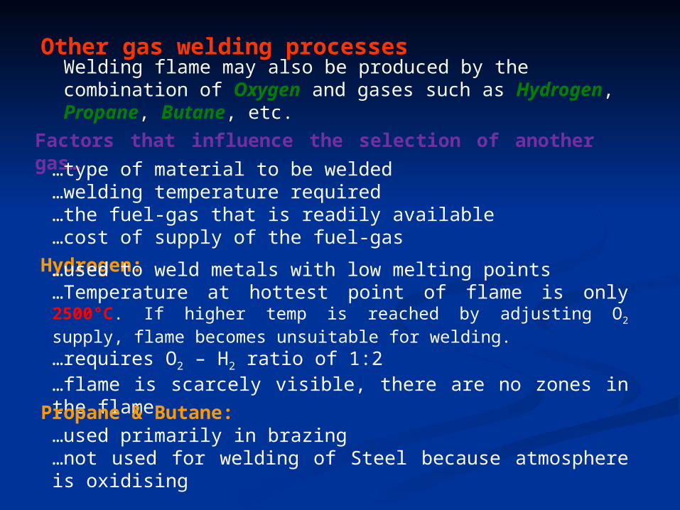
Other gas welding processesWelding flame may also be produced by the combination of Oxygen and gases such as Hydrogen, Propane, Butane, etc.
Factors that influence the selection of another gas…
…type of material to be welded…welding temperature required…the fuel-gas that is readily available…cost of supply of the fuel-gas
Hydrogen:…used to weld metals with low melting points…Temperature at hottest point of flame is only 2500°C. If higher temp is reached by adjusting O2 supply, flame becomes unsuitable for welding.
…requires O2 – H2 ratio of 1:2…flame is scarcely visible, there are no zones in the flame
Propane & Butane:
…used primarily in brazing…not used for welding of Steel because atmosphere is oxidising
Braze welding…intermediate between true welding and brazing…method of welding where a weld is made using a non-ferrous filler metal having a melting point below that of the base metal, but above 427°C…filer metal is deposited directly in the required region
Brazing…Used with close-fitted surfaces…Filler alloy is fed to one or few points and is drawn into the rest of the joint by capillary action
ARC WELDINGARC WELDING
Arc welding is a group of welding Arc welding is a group of welding process where in coalescence is process where in coalescence is produced by heating with an produced by heating with an electrical arc or arcs, mostly without electrical arc or arcs, mostly without the application of pressure and with the application of pressure and with or without the use of filler metal or without the use of filler metal depending upon the base plate depending upon the base plate thickness.thickness.
ARC WELDING PROCESSARC WELDING PROCESS
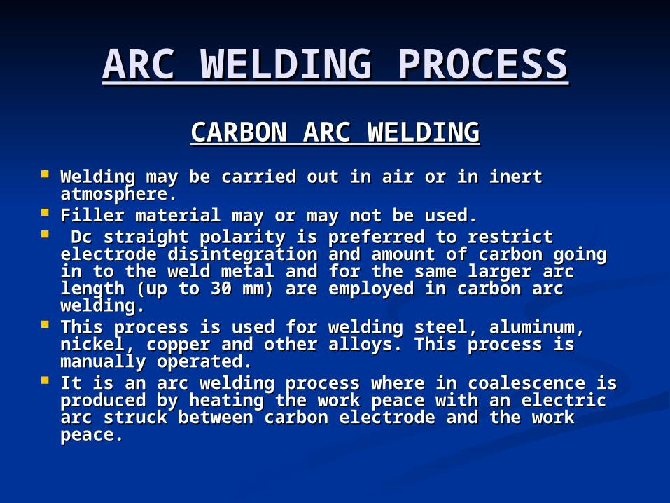
CARBON ARC WELDINGCARBON ARC WELDING Welding may be carried out in air or in inert Welding may be carried out in air or in inert
atmosphere. atmosphere. Filler material may or may not be used.Filler material may or may not be used. Dc straight polarity is preferred to restrict electrode Dc straight polarity is preferred to restrict electrode
disintegration and amount of carbon going in to the disintegration and amount of carbon going in to the weld metal and for the same larger arc length (up to weld metal and for the same larger arc length (up to 30 mm) are employed in carbon arc welding. 30 mm) are employed in carbon arc welding.
This process is used for welding steel, aluminum, This process is used for welding steel, aluminum, nickel, copper and other alloys. This process is nickel, copper and other alloys. This process is manually operated.manually operated.
It is an arc welding process where in coalescence is It is an arc welding process where in coalescence is produced by heating the work peace with an electric produced by heating the work peace with an electric arc struck between carbon electrode and the work arc struck between carbon electrode and the work peace. peace.
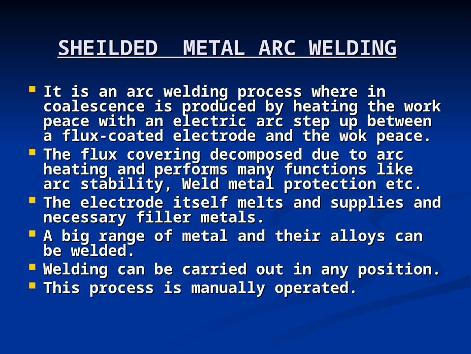
SHEILDED METAL ARC WELDINGSHEILDED METAL ARC WELDING It is an arc welding process where in It is an arc welding process where in
coalescence is produced by heating the coalescence is produced by heating the work peace with an electric arc step up work peace with an electric arc step up between a flux-coated electrode and the wok between a flux-coated electrode and the wok peace. peace.
The flux covering decomposed due to arc The flux covering decomposed due to arc heating and performs many functions like heating and performs many functions like arc stability, Weld metal protection etc. arc stability, Weld metal protection etc.
The electrode itself melts and supplies and The electrode itself melts and supplies and necessary filler metals. necessary filler metals.
A big range of metal and their alloys can be A big range of metal and their alloys can be welded. welded.
Welding can be carried out in any position. Welding can be carried out in any position. This process is manually operated.This process is manually operated.
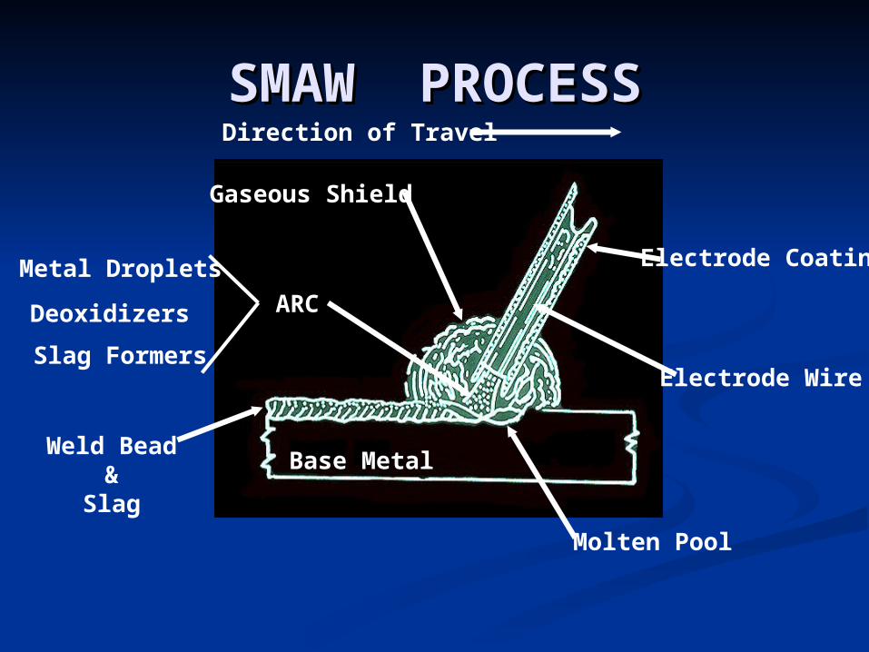
SMAW PROCESSSMAW PROCESS
Base Metal
Metal Droplets
ARCDeoxidizers
Slag Formers
Weld Bead&
Slag
Gaseous Shield
Electrode Coating
Electrode Wire
Direction of Travel
Molten Pool
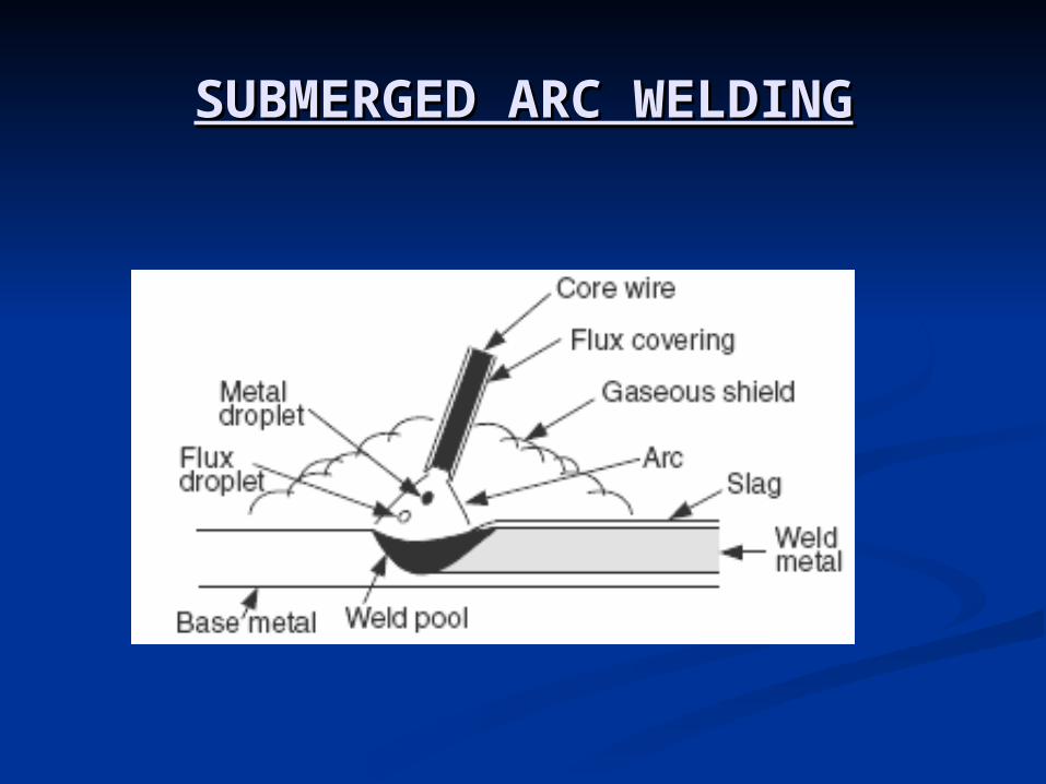
SUBMERGED ARC WELDINGSUBMERGED ARC WELDING
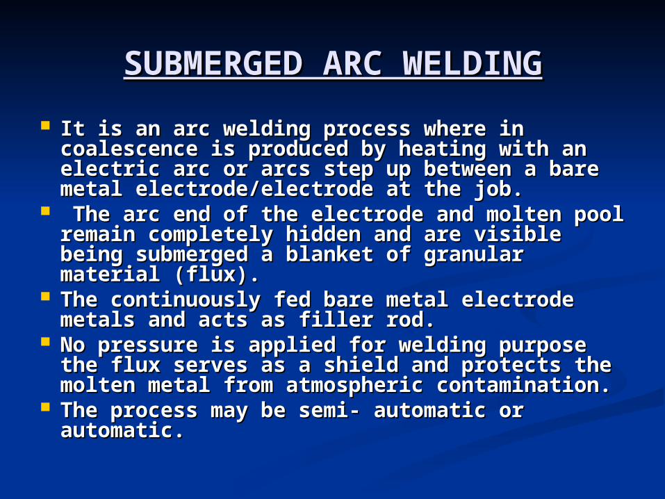
It is an arc welding process where in It is an arc welding process where in coalescence is produced by heating with an coalescence is produced by heating with an electric arc or arcs step up between a bare electric arc or arcs step up between a bare metal electrode/electrode at the job.metal electrode/electrode at the job.
The arc end of the electrode and molten pool The arc end of the electrode and molten pool remain completely hidden and are visible being remain completely hidden and are visible being submerged a blanket of granular material submerged a blanket of granular material (flux). (flux).
The continuously fed bare metal electrode The continuously fed bare metal electrode metals and acts as filler rod. metals and acts as filler rod.
No pressure is applied for welding purpose the No pressure is applied for welding purpose the flux serves as a shield and protects the molten flux serves as a shield and protects the molten metal from atmospheric contamination.metal from atmospheric contamination.
The process may be semi- automatic or The process may be semi- automatic or automatic.automatic.
SUBMERGED ARC WELDINGSUBMERGED ARC WELDING
TUGSTEN INERT GAS WELDINGTUGSTEN INERT GAS WELDING
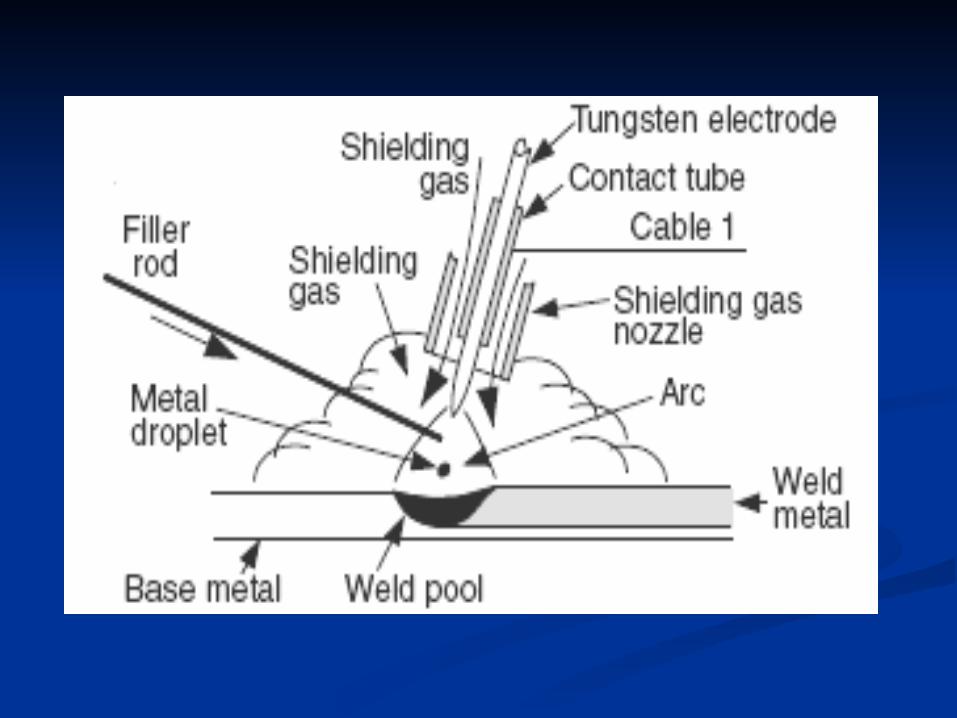
It is an arc welding process where in It is an arc welding process where in coalescence is produced by heating the job coalescence is produced by heating the job with an electric arc struck between a tungsten with an electric arc struck between a tungsten electrode and the job.electrode and the job.
A shielding gas (argon, helium, nitrogen, etc) A shielding gas (argon, helium, nitrogen, etc) is used to avoid atmospheric contamination of is used to avoid atmospheric contamination of the molten weld pool. the molten weld pool.
A filler metal may be added if required. A filler metal may be added if required. In this process a non- consumable electrode In this process a non- consumable electrode
(tungsten) is used. (tungsten) is used. TIG welding is very much suitable for high TIG welding is very much suitable for high
quality welding of thin materials as thin as quality welding of thin materials as thin as 0.125 mm0.125 mm. .
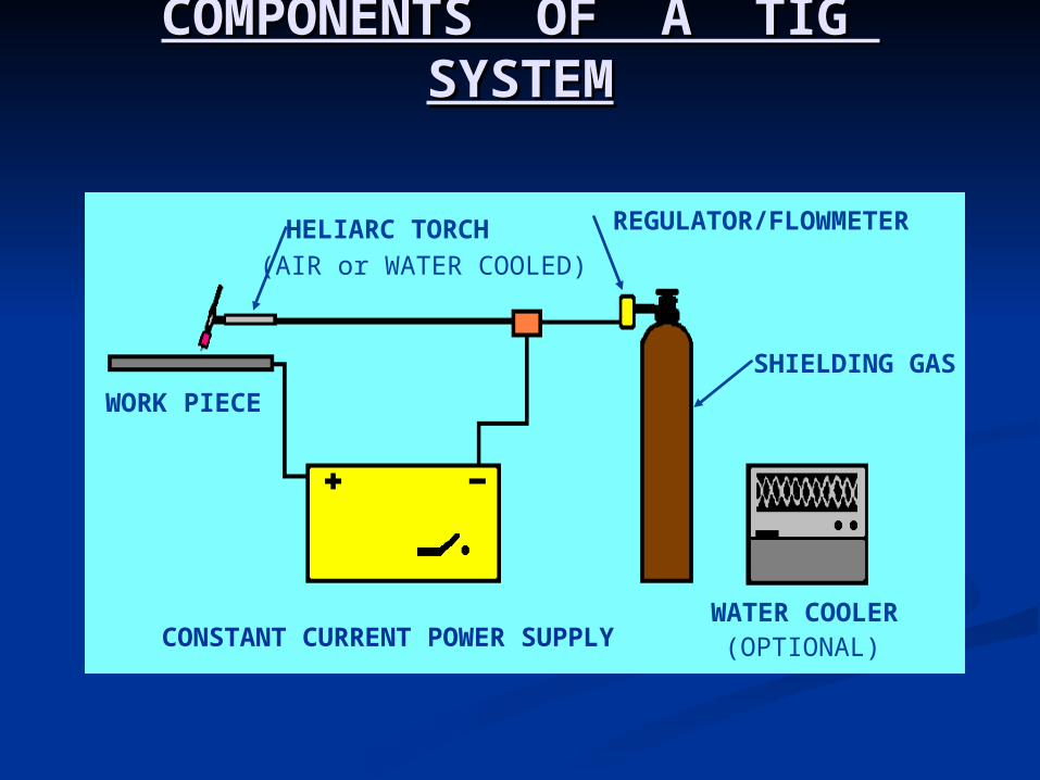
COMPONENTS OF A TIG SYSTEMCOMPONENTS OF A TIG SYSTEM
SHIELDING GAS
WATER COOLERCONSTANT CURRENT POWER SUPPLY
WORK PIECE
HELIARC TORCH REGULATOR/FLOWMETER
(AIR or WATER COOLED)
(OPTIONAL)
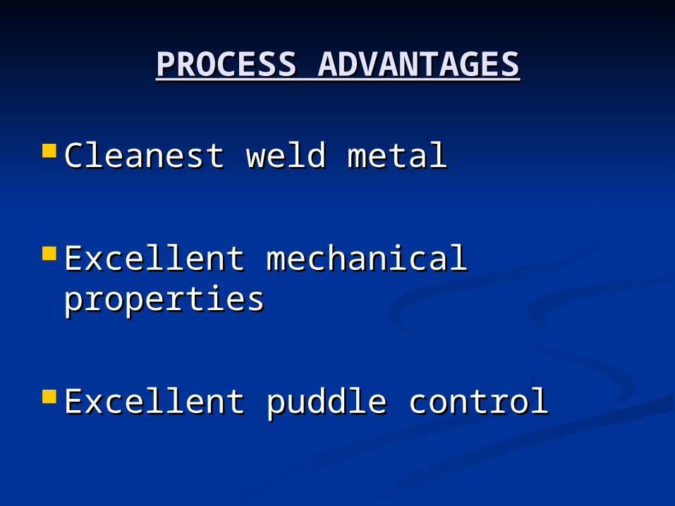
PROCESS ADVANTAGESPROCESS ADVANTAGES
Cleanest weld metalCleanest weld metal
Excellent mechanical propertiesExcellent mechanical properties
Excellent puddle controlExcellent puddle control
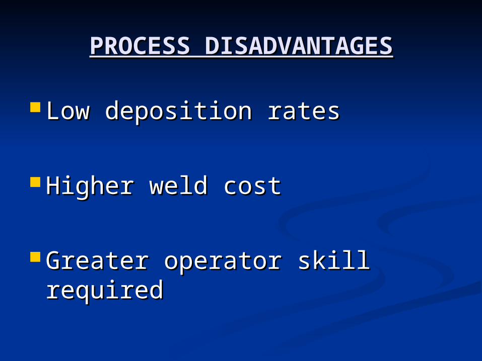
PROCESS DISADVANTAGESPROCESS DISADVANTAGES
Low deposition ratesLow deposition rates
Higher weld costHigher weld cost
Greater operator skill requiredGreater operator skill required
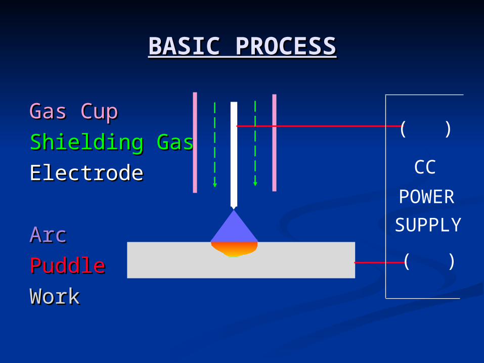
Gas CupGas Cup
Shielding GasShielding Gas
ElectrodeElectrode
ArcArc
PuddlePuddle
WorkWork
BASIC PROCESSBASIC PROCESS
( )
( )
CC
POWER
SUPPLY
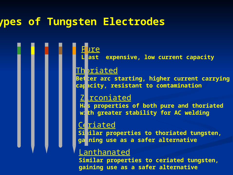
PureLeast expensive, low current capacity
ZirconiatedHas properties of both pure and thoriatedwith greater stability for AC welding
ThoriatedBetter arc starting, higher current carryingcapacity, resistant to comtamination
CeriatedSimilar properties to thoriated tungsten,gaining use as a safer alternative
LanthanatedSimilar properties to ceriated tungsten,gaining use as a safer alternative
Types of Tungsten Electrodes
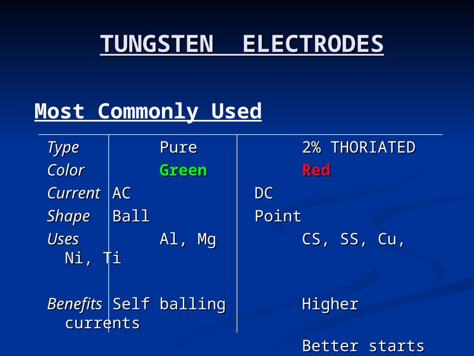
TUNGSTEN ELECTRODESTUNGSTEN ELECTRODES
TypeType PurePure 2% 2% THORIATEDTHORIATED
ColorColor GreenGreen RedRed
CurrentCurrent ACAC DCDC
ShapeShape BallBall PointPoint
UsesUses Al, MgAl, Mg CS, SS, Cu, Ni, CS, SS, Cu, Ni, TiTi
BenefitsBenefits Self ballingSelf balling Higher Higher currentscurrents
Better startsBetter starts
Most Commonly Used
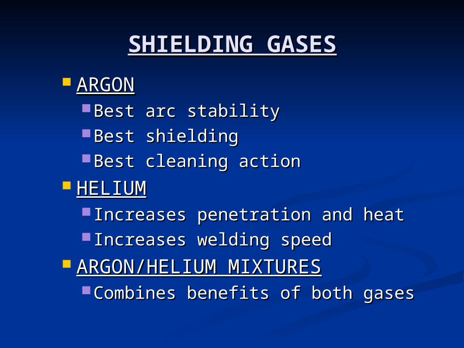
SHIELDING GASESSHIELDING GASES
ARGONARGONBest arc stabilityBest arc stabilityBest shieldingBest shieldingBest cleaning actionBest cleaning action
HELIUMHELIUM Increases penetration and heatIncreases penetration and heat Increases welding speedIncreases welding speed
ARGON/HELIUM MIXTURESARGON/HELIUM MIXTURESCombines benefits of both gasesCombines benefits of both gases
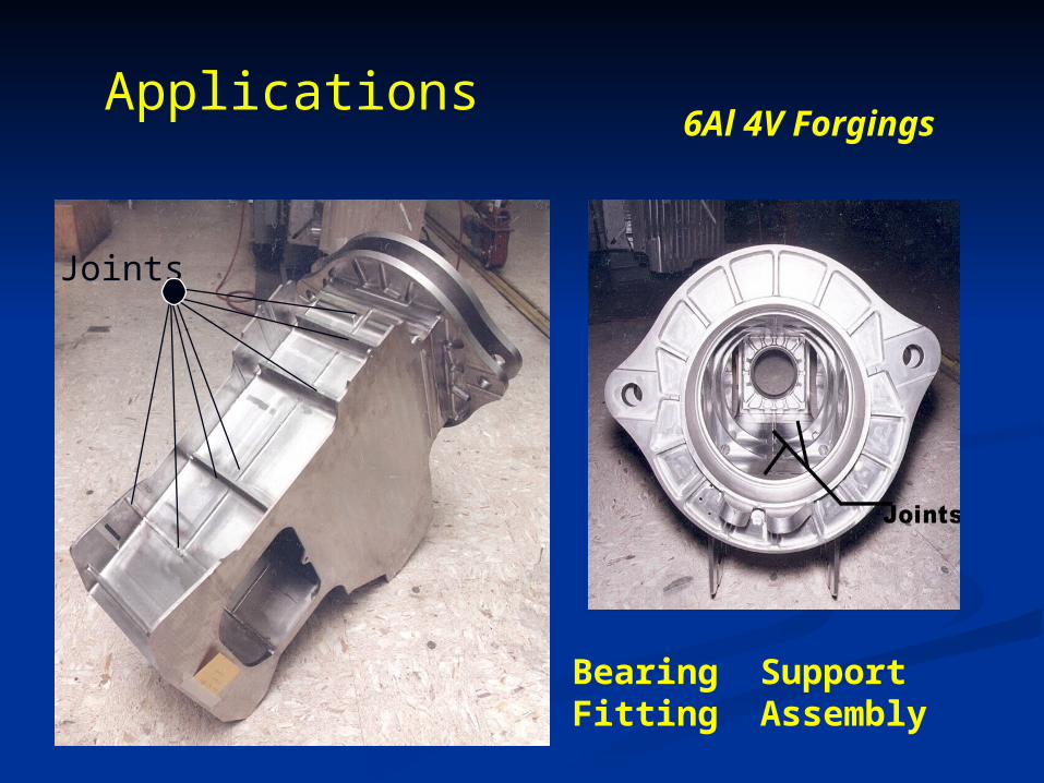
Joints
Bearing SupportFitting Assembly
Applications6Al 4V Forgings
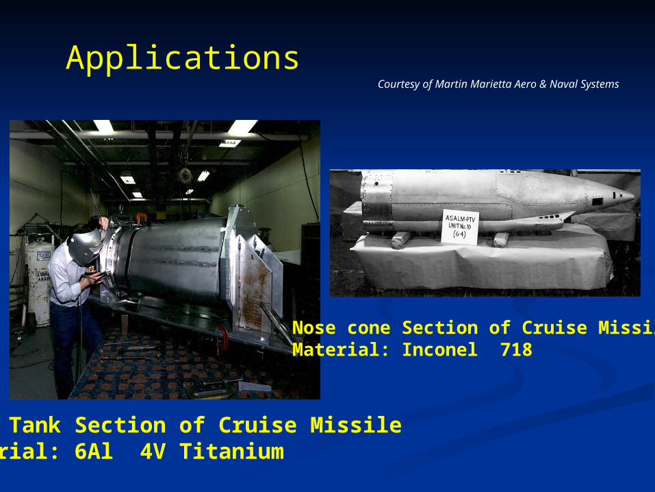
Applications
Fuel Tank Section of Cruise MissileMaterial: 6Al 4V Titanium
Nose cone Section of Cruise MissileMaterial: Inconel 718
Courtesy of Martin Marietta Aero & Naval Systems
METAL INERT GAS WELDINGMETAL INERT GAS WELDING
It is an arc welding process where in coalescence It is an arc welding process where in coalescence is produced by heating the job with an electric is produced by heating the job with an electric arc established between a continuously fed metal arc established between a continuously fed metal electrode and the job. electrode and the job.
No flux is used but the arc and molten metal are No flux is used but the arc and molten metal are shielded by an inert gas, which may be argon, shielded by an inert gas, which may be argon, helium, carbon dioxide or a gas mixture.helium, carbon dioxide or a gas mixture.
Because of continuously fed electrode MIG Because of continuously fed electrode MIG welding process is much faster as compared to welding process is much faster as compared to TIG welding and can produce deep penetration TIG welding and can produce deep penetration joints.joints.
All commercial metals and alloys can be welded. All commercial metals and alloys can be welded.

MIG WELDING SYSTEMMIG WELDING SYSTEM
Regulator/ flowmeter: R-50-FM-580
High Pressure Gas Cylinder, Shield Gas
Filler Metal, (Electrode): Spoolarc 86
Wire Feeder: Digipulse
Constant Voltage Power Source: Digipulse 450
Welding Torch/Mig Gun: MT400
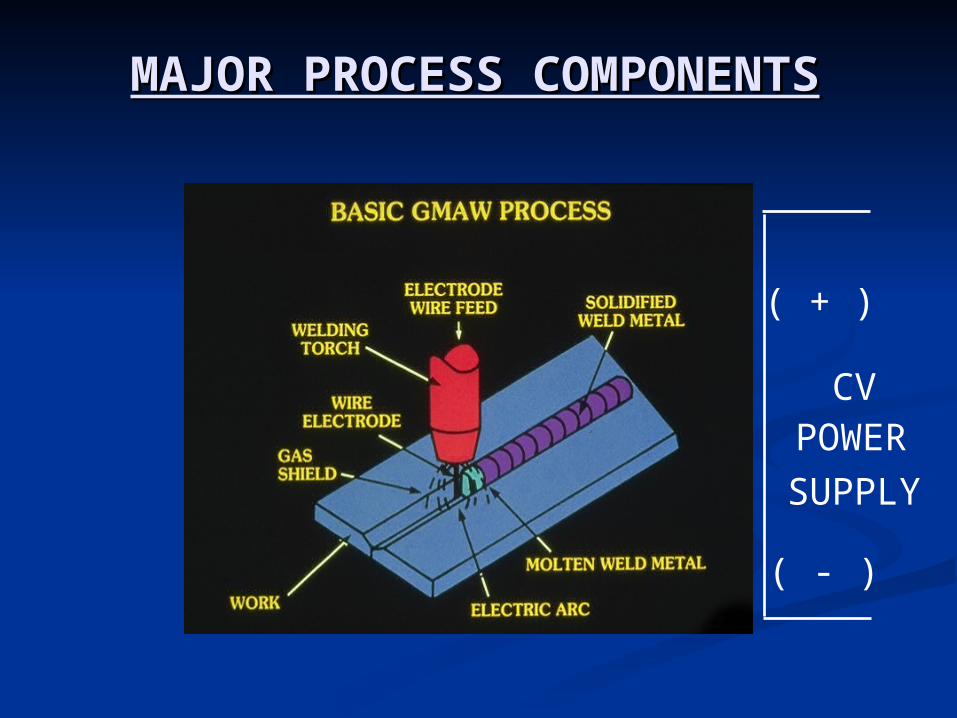
MAJOR PROCESS COMPONENTSMAJOR PROCESS COMPONENTS
( + )
( - )
CVPOWER
SUPPLY
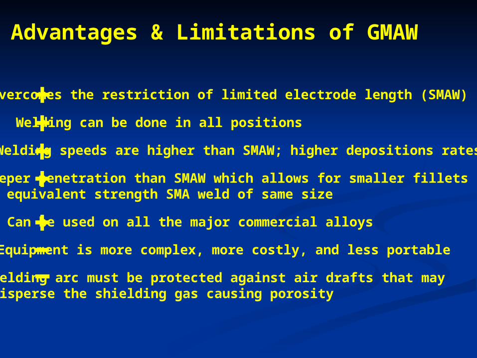
Advantages & Limitations of GMAW
Overcomes the restriction of limited electrode length (SMAW)
Equipment is more complex, more costly, and less portable
Welding can be done in all positions
Welding speeds are higher than SMAW; higher depositions rates
Deeper penetration than SMAW which allows for smaller fillets foran equivalent strength SMA weld of same size
Can be used on all the major commercial alloys
Welding arc must be protected against air drafts that maydisperse the shielding gas causing porosity
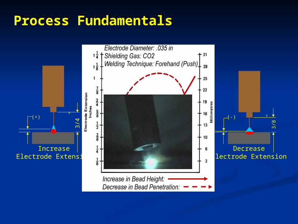
(-)
DecreaseElectrode Extension
3/8
”(+)
3/4”
IncreaseElectrode Extension
Process FundamentalsProcess Fundamentals
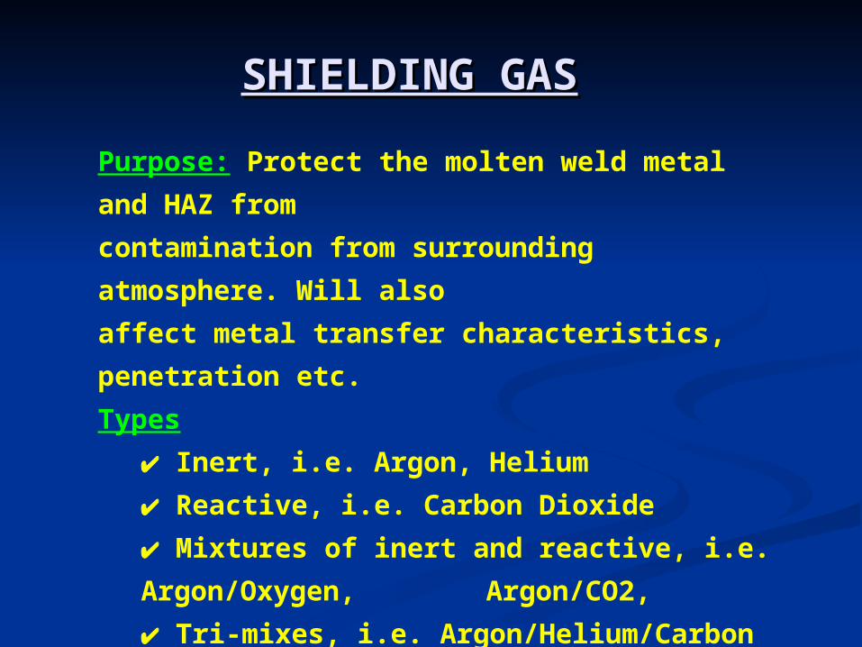
Purpose: Protect the molten weld metal and HAZ
from
contamination from surrounding atmosphere. Will
also
affect metal transfer characteristics, penetration etc.
Types
Inert, i.e. Argon, Helium
Reactive, i.e. Carbon Dioxide
Mixtures of inert and reactive, i.e.
Argon/Oxygen, Argon/CO2,
Tri-mixes, i.e. Argon/Helium/Carbon Dioxide
SHIELDING GASSHIELDING GAS
SHIELDING GAS PROPERTIESSHIELDING GAS PROPERTIES
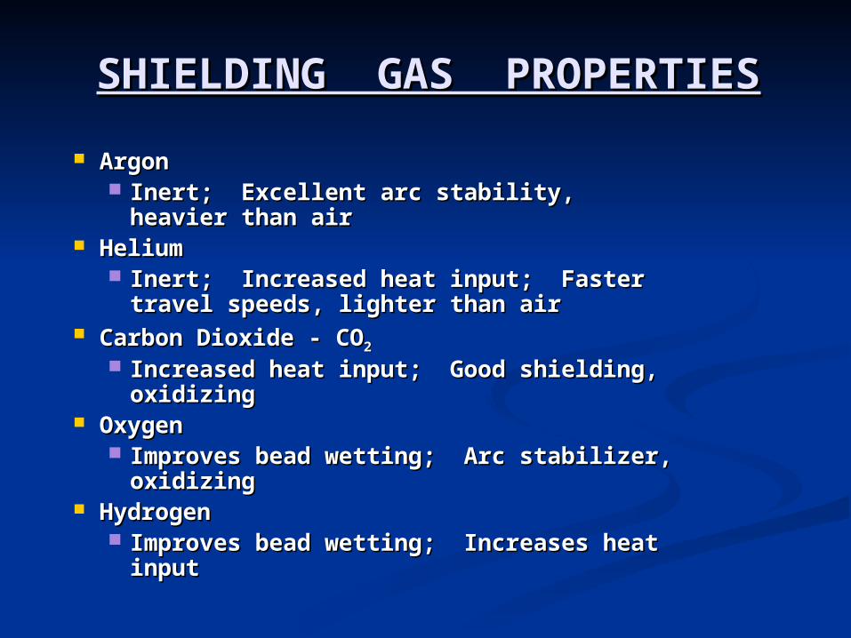
ArgonArgon Inert; Excellent arc stability, heavier Inert; Excellent arc stability, heavier
than airthan air HeliumHelium
Inert; Increased heat input; Faster Inert; Increased heat input; Faster travel speeds, lighter than airtravel speeds, lighter than air
Carbon Dioxide - COCarbon Dioxide - CO22
Increased heat input; Good shielding, Increased heat input; Good shielding, oxidizingoxidizing
OxygenOxygen Improves bead wetting; Arc stabilizer, Improves bead wetting; Arc stabilizer,
oxidizingoxidizing HydrogenHydrogen
Improves bead wetting; Increases heat Improves bead wetting; Increases heat inputinput
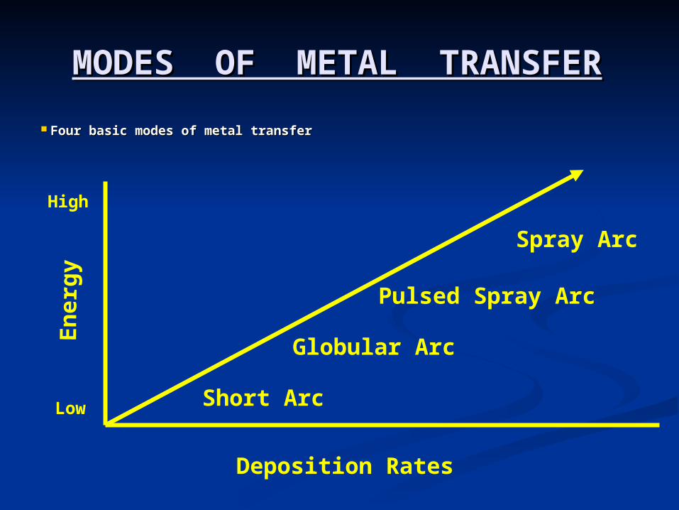
MODES OF METAL TRANSFERMODES OF METAL TRANSFER
Four basic modes of metal transferFour basic modes of metal transfer
Short Arc
Globular Arc
Pulsed Spray Arc
Spray Arc
Deposition Rates
En
erg
y
Low
High
SHORT ARC TRANSFERSHORT ARC TRANSFER
Generally uses small diameter Generally uses small diameter solid wiressolid wires
Uses low currents and Uses low currents and voltagesvoltages
Low heat inputLow heat inputGood for welding thin gauge and Good for welding thin gauge and
out-of-positionout-of-position
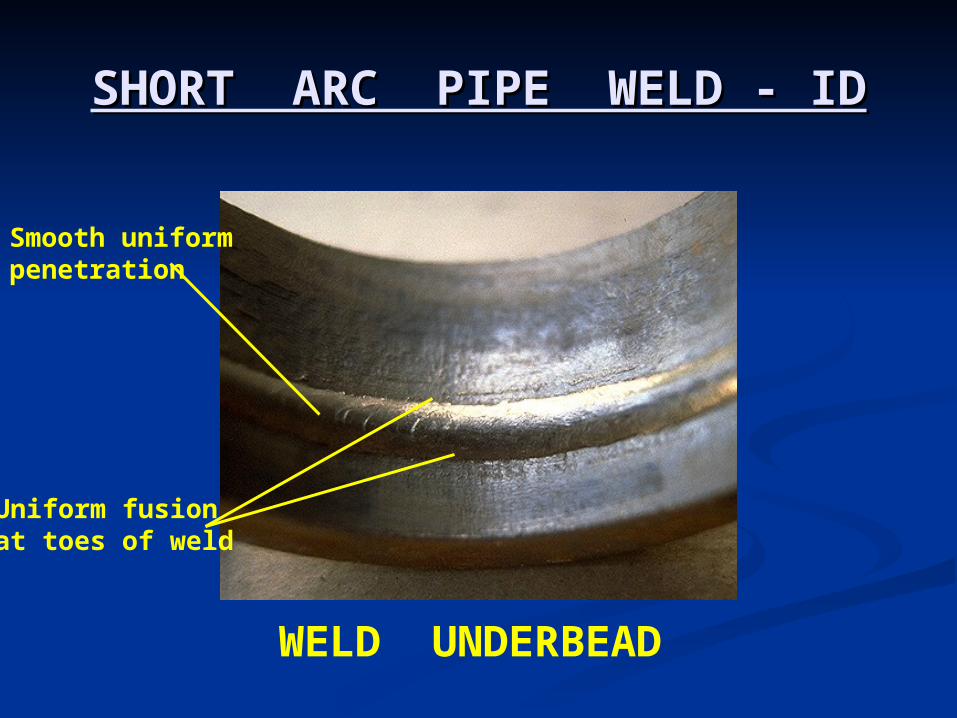
SHORT ARC PIPE WELD - IDSHORT ARC PIPE WELD - ID
WELD UNDERBEAD
Smooth uniformpenetration
Uniform fusionat toes of weld
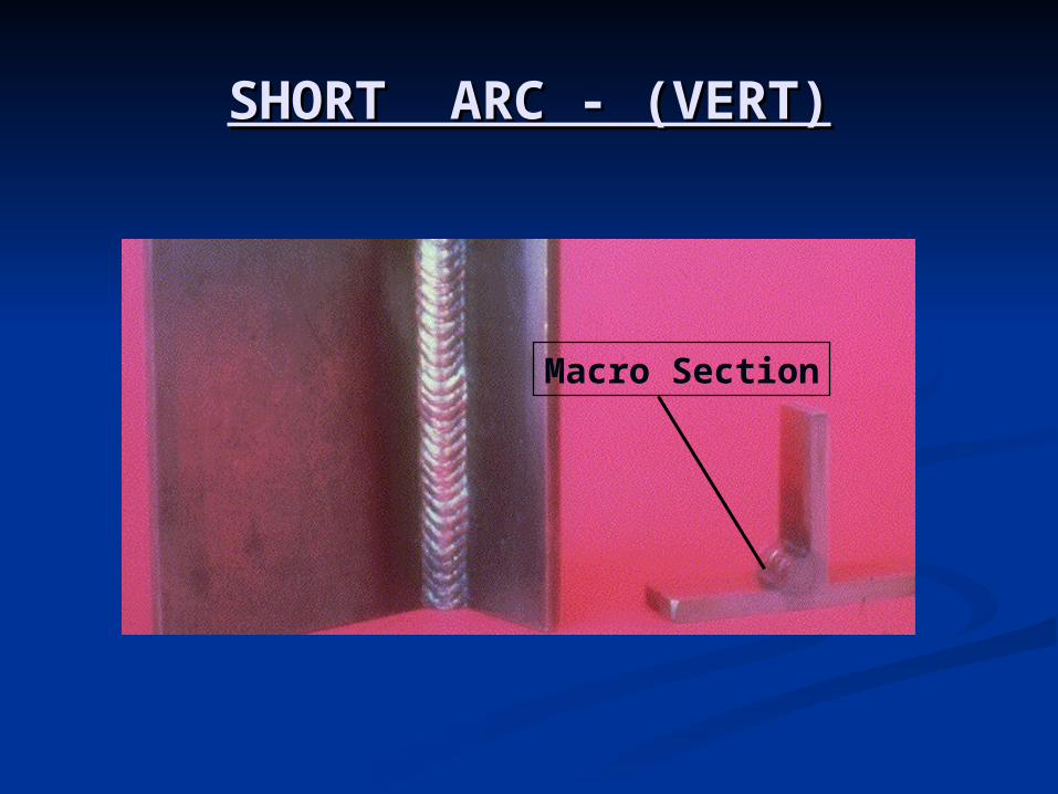
SHORT ARC - (VERT)SHORT ARC - (VERT)
Macro Section
GLOBULAR TRANSFERGLOBULAR TRANSFER
The type of transfer achieved when The type of transfer achieved when using COusing CO22 shielding gas. shielding gas.
Good penetration and higher speedsGood penetration and higher speeds
Excessive weld spatterExcessive weld spatter
Increased clean-up costIncreased clean-up cost
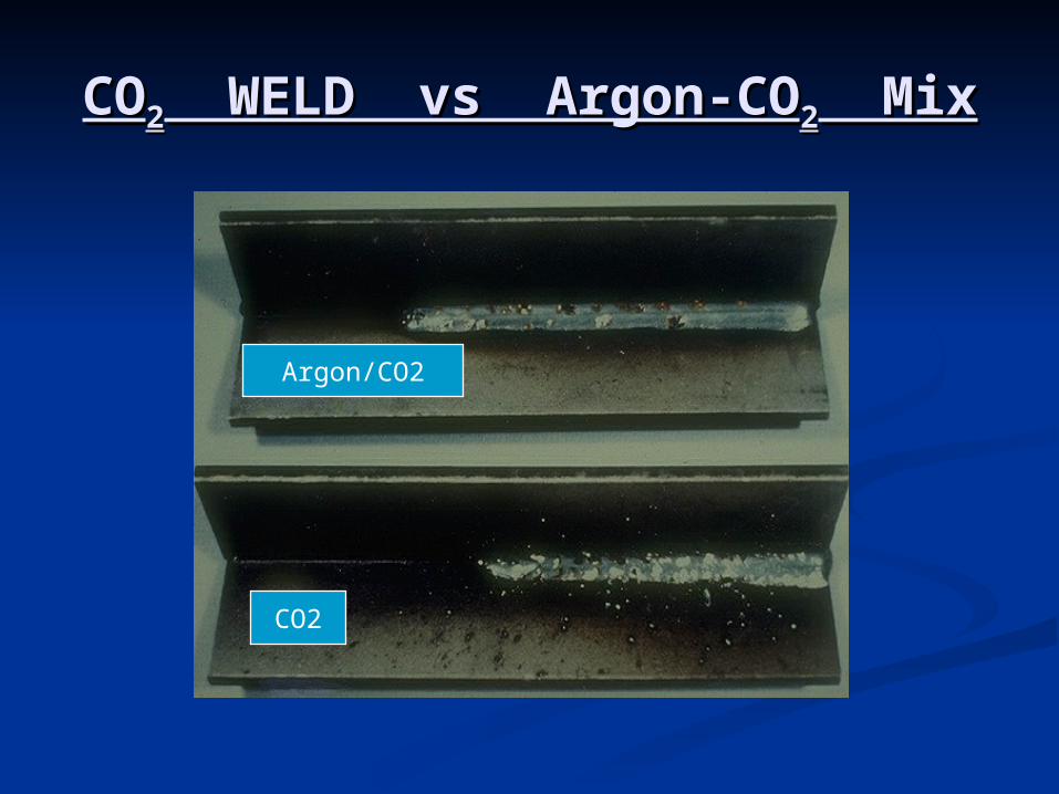
COCO22 WELD vs Argon-CO WELD vs Argon-CO22 Mix Mix
Argon/CO2
CO2

SPRAY TRANSFERSPRAY TRANSFER
Spray transfer occurs when:Spray transfer occurs when:
Welding current is above the Welding current is above the transition pointtransition point
Shielding gas is greater than 80% Shielding gas is greater than 80% argonargon
Arc voltage is high enough that it does Arc voltage is high enough that it does not short not short circuit - about 26-30 voltscircuit - about 26-30 volts
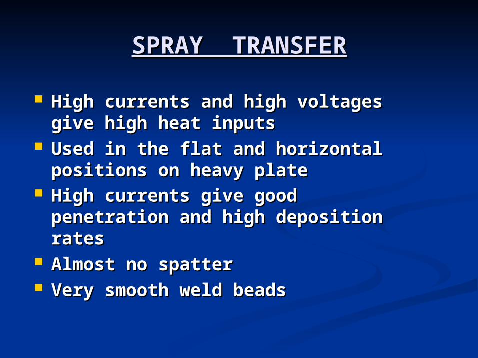
SPRAY TRANSFERSPRAY TRANSFER
High currents and high voltages High currents and high voltages give high heat inputsgive high heat inputs
Used in the flat and horizontal Used in the flat and horizontal positions on heavy platepositions on heavy plate
High currents give good High currents give good penetration and high deposition penetration and high deposition ratesrates
Almost no spatterAlmost no spatter Very smooth weld beadsVery smooth weld beads
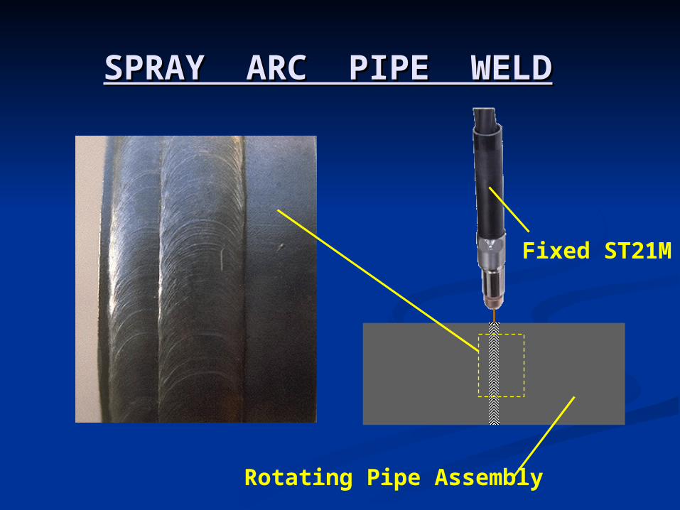
SPRAY ARC PIPE WELDSPRAY ARC PIPE WELD
Fixed ST21M
Rotating Pipe Assembly
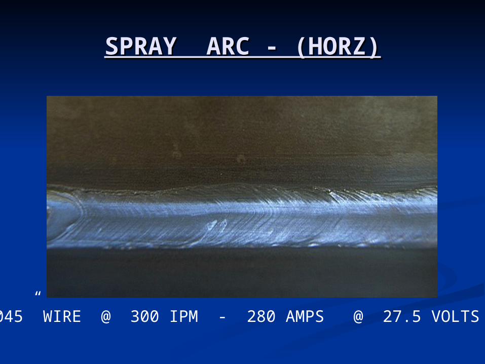
SPRAY ARC - (HORZ)SPRAY ARC - (HORZ)
.045” WIRE @ 300 IPM - 280 AMPS @ 27.5 VOLTS
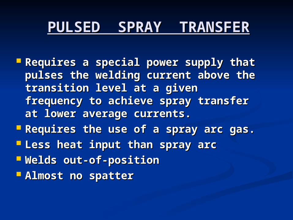
PULSED SPRAY TRANSFERPULSED SPRAY TRANSFER
Requires a special power supply that Requires a special power supply that pulses the welding current above the pulses the welding current above the transition level at a given frequency transition level at a given frequency to achieve spray transfer at lower to achieve spray transfer at lower average currents.average currents.
Requires the use of a spray arc gas.Requires the use of a spray arc gas. Less heat input than spray arcLess heat input than spray arc Welds out-of-positionWelds out-of-position Almost no spatterAlmost no spatter
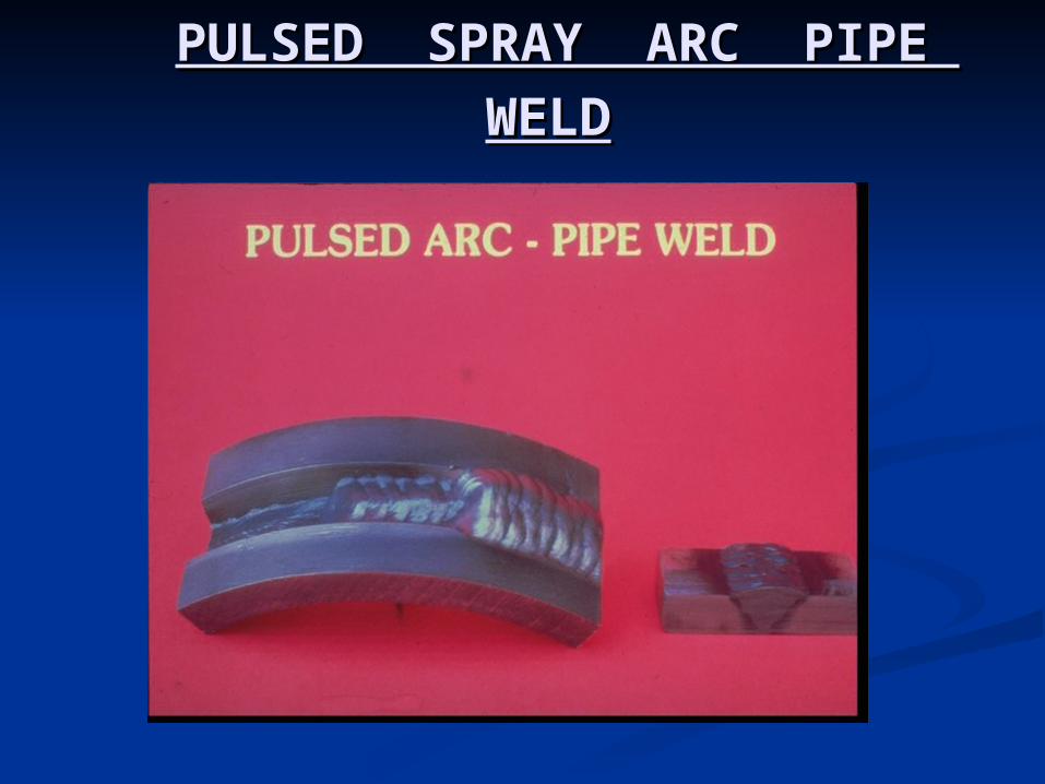
PULSED SPRAY ARC PIPE WELDPULSED SPRAY ARC PIPE WELD
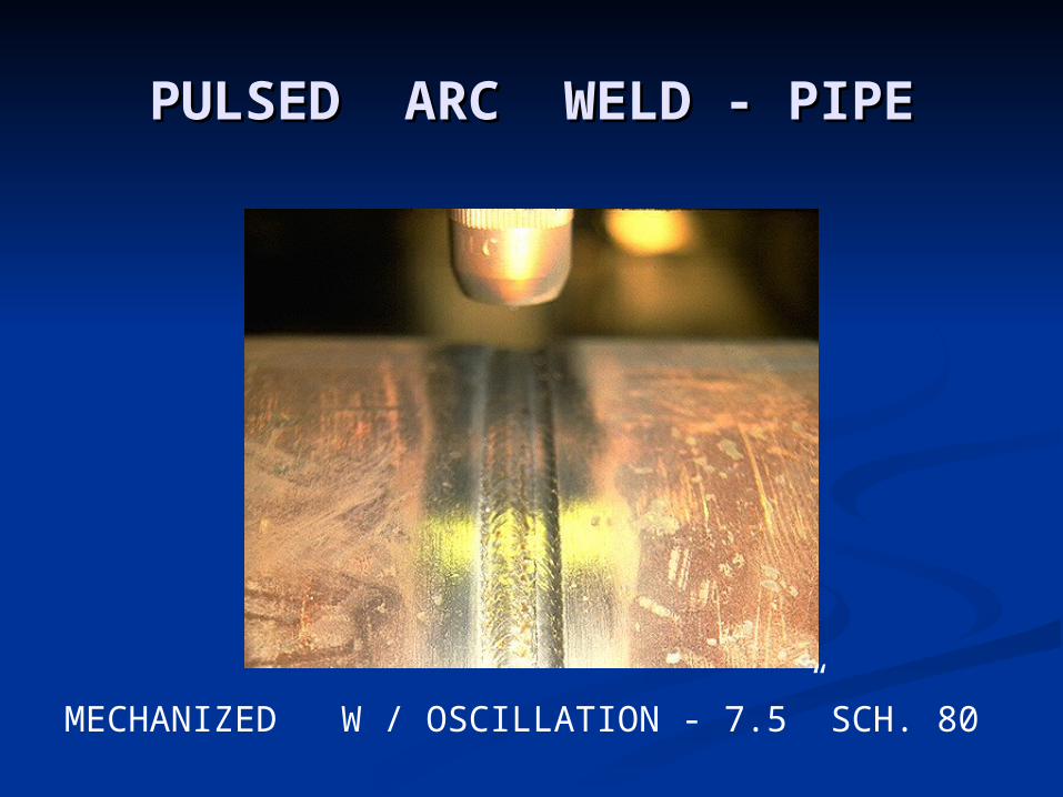
PULSED ARC WELD - PIPEPULSED ARC WELD - PIPE
MECHANIZED W / OSCILLATION - 7.5” SCH. 80
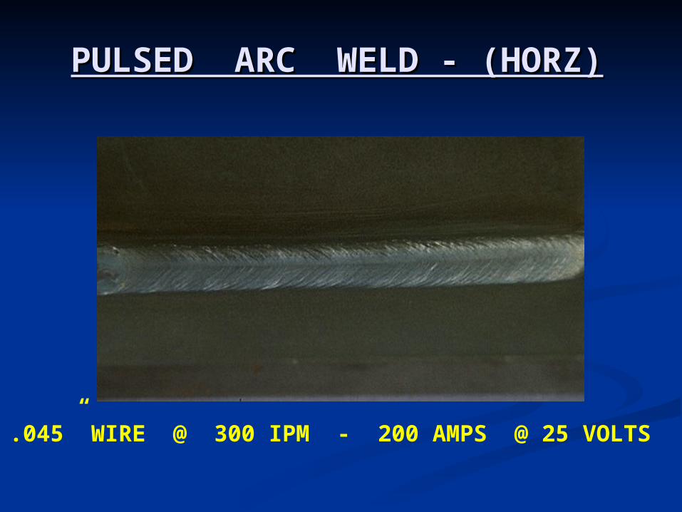
PULSED ARC WELD - (HORZ)PULSED ARC WELD - (HORZ)
.045” WIRE @ 300 IPM - 200 AMPS @ 25 VOLTS
PULSED ARC WELD - (VERT)PULSED ARC WELD - (VERT)
Macro Section
ELECTRO SLAG WELDINGELECTRO SLAG WELDING
It is an arc welding process where in It is an arc welding process where in coalescence is produced by molten coalescence is produced by molten slag which melts the filler metal and slag which melts the filler metal and surface of the work to welded. surface of the work to welded.
Welding flux is added and melts it to Welding flux is added and melts it to form the slag arc heats.form the slag arc heats.
Much thicker steel can be welded in Much thicker steel can be welded in single pass.single pass.
Thickness up to 450mm in plain and Thickness up to 450mm in plain and alloy steel can be welded.alloy steel can be welded.
ELECTRO GAS WELDINGELECTRO GAS WELDING
It is an arc welding process where in It is an arc welding process where in coalescence is produced by the gas or coalescence is produced by the gas or heat require for welding is obtained heat require for welding is obtained by maintaining a continuous electric by maintaining a continuous electric arc between the electrodes and the arc between the electrodes and the moten weld poll during welding moten weld poll during welding operation.operation.
An inert ( ex:CO2) shields the molten An inert ( ex:CO2) shields the molten weld pool from oxidation, only DC can weld pool from oxidation, only DC can be used for electro gas welding. be used for electro gas welding.
Plates 12.5mm to 275mm thick are Plates 12.5mm to 275mm thick are most commonly welded. Welding is most commonly welded. Welding is done in one pass.done in one pass.
PLASMA GAS WELDINGPLASMA GAS WELDING
Plasma arc welding is an arc welding Plasma arc welding is an arc welding process where in coalescence is produced process where in coalescence is produced by heat obtained from a constructed arc by heat obtained from a constructed arc step up between tungsten/ alloy tungsten.step up between tungsten/ alloy tungsten.
Electrode and the water-cooled nozzle as Electrode and the water-cooled nozzle as between tungsten/alloy tungsten electrode between tungsten/alloy tungsten electrode and the job. and the job.
The process employs two inert gases, one The process employs two inert gases, one forms the arc plasma and the second forms the arc plasma and the second shields the arc plasma. shields the arc plasma.
Filler metal may or may not be added. Filler metal may or may not be added. All metal and alloys can be welded.All metal and alloys can be welded.
ARC SPOT WELDINGARC SPOT WELDING It is an arc welding process at zero arc travel It is an arc welding process at zero arc travel
speed where in coalescence between two speed where in coalescence between two coating surfaces is obtained with the help of a coating surfaces is obtained with the help of a spot formed by heating with air electric arc spot formed by heating with air electric arc step up between a tungsten electrode and one step up between a tungsten electrode and one of the two closely fit surface. of the two closely fit surface.
Filler metals may or may not be used Filler metals may or may not be used depending upon the materials to be welded.depending upon the materials to be welded.
The process involves less maintenance cost.The process involves less maintenance cost. The process is normally free from smoke and The process is normally free from smoke and
spatter.spatter. All commercial metals and alloys can be easily All commercial metals and alloys can be easily
welded. welded.
STUD WELDINGSTUD WELDING It is an arc welding process where in coalescence is It is an arc welding process where in coalescence is
produced by heating with an electric arc drawn produced by heating with an electric arc drawn between a metal stud, bolt, rivet or a similar part between a metal stud, bolt, rivet or a similar part and the base metal. and the base metal.
Arc is maintained till a molten pool is created in the Arc is maintained till a molten pool is created in the base metal and the arcing end of the stud is heated base metal and the arcing end of the stud is heated to melting point. to melting point.
At this stage, arc extinguished and the stud is forced At this stage, arc extinguished and the stud is forced in to the molten metal pod of the metal to form the in to the molten metal pod of the metal to form the weld. weld.
The molten metal is shielded by a ferrule and a flux The molten metal is shielded by a ferrule and a flux or inert shield gas. or inert shield gas.
A simple, efficient economic and very fast method of A simple, efficient economic and very fast method of joining pins, bolts, studs, rivets, rods etc. to a plate joining pins, bolts, studs, rivets, rods etc. to a plate or a structure. or a structure.
Most of the ferrous and nonferrous materials and Most of the ferrous and nonferrous materials and their alloys can be stud welded easily.their alloys can be stud welded easily.
RESISTANCE WELDING RESISTANCE WELDING PROCESSESPROCESSES
Resistance welding is a group of Resistance welding is a group of welding processes wherein coalescence welding processes wherein coalescence is produced by the heat obtained from is produced by the heat obtained from the resistance offered by the work piece the resistance offered by the work piece to the flow of electric current in a to the flow of electric current in a circuit of which the work is a part, and, circuit of which the work is a part, and, by the application of pressure. No filler by the application of pressure. No filler metal is needed. metal is needed.
The different types of resistance The different types of resistance welding are as followswelding are as follows::
SPOT WELDINGSPOT WELDING It is a welding process in which over It is a welding process in which over
lapping sheets are joined by local fusion at lapping sheets are joined by local fusion at one or more spots by the heat generated by one or more spots by the heat generated by resistance to the flow of electric current resistance to the flow of electric current through work piece that are held together through work piece that are held together under force by two electrodes one above under force by two electrodes one above the other below the two overlapping the other below the two overlapping sheets.sheets.
High speed of welding, the skilled workers, High speed of welding, the skilled workers, and operation may be made automatic or and operation may be made automatic or semi-automatic are the advantages. semi-automatic are the advantages.
Spot welding of two 12.5mm thick steel Spot welding of two 12.5mm thick steel plates has been done satisfactorily.plates has been done satisfactorily.
SEAM WELDINGSEAM WELDING
Seam welding is a resistance welding Seam welding is a resistance welding process where in coalescence at the process where in coalescence at the saying surfaces is produced by heat saying surfaces is produced by heat obtained from resistance to electric obtained from resistance to electric current (flow) through the work parts held current (flow) through the work parts held together under pressure by electrodes. together under pressure by electrodes.
The resulting weld is a series of The resulting weld is a series of overlapping resistance spot welds made overlapping resistance spot welds made progressively along a joint by rotating the progressively along a joint by rotating the circular electrodes.circular electrodes.
All commercial metals and their alloys are All commercial metals and their alloys are successfully welded by seam welding.successfully welded by seam welding.
PROJECTION WELDINGPROJECTION WELDING
Projection welding is a resistance welding Projection welding is a resistance welding process where in coalescence in produced process where in coalescence in produced by heat obtained from resistance to by heat obtained from resistance to electric current (flow) through the work electric current (flow) through the work parts held together under pressure by parts held together under pressure by electrodes. electrodes.
The resulting welds are localized The resulting welds are localized predetermined points by projections, predetermined points by projections, embossment or intersections.embossment or intersections.
Projection welds can be made in metals Projection welds can be made in metals that are too thick to be joined by spot that are too thick to be joined by spot welding. welding.
A number of welds can be made A number of welds can be made simultaneously. simultaneously.

RESISTANCE BUTT WELDINGRESISTANCE BUTT WELDING
Upset butt welding is a resistance or the entire Upset butt welding is a resistance or the entire area of butting surfaces by the heat obtained area of butting surfaces by the heat obtained from the resistance of electric current through from the resistance of electric current through the area of contact of these surfaces. the area of contact of these surfaces.
Pressure is supplied before heating is started Pressure is supplied before heating is started and is maintained throughout the heating and is maintained throughout the heating period. period.
This pressure or force lateral on increased to This pressure or force lateral on increased to give a forging squeeze when the welding give a forging squeeze when the welding temperature (1600deg to 1700deg) has been temperature (1600deg to 1700deg) has been reached when sufficient upset has been reached when sufficient upset has been produced the welding current is cutoff and the produced the welding current is cutoff and the force is removed.force is removed.
For welding of small ferrous and non-ferrous For welding of small ferrous and non-ferrous strips and rods for welding longitudinal and strips and rods for welding longitudinal and transverse butt joint. transverse butt joint.
Flash welding is a resistance welding Flash welding is a resistance welding process where in coalescence is produced. process where in coalescence is produced.
Simultaneously over the entire area of Simultaneously over the entire area of abutting surface by the heat obtained abutting surface by the heat obtained from the resistance to electric current from the resistance to electric current between the two surfaces and by the between the two surfaces and by the application of pressure after heating is application of pressure after heating is substantially completed.substantially completed.
Flashing and upsetting are accomplished Flashing and upsetting are accomplished by explosion of metal from the joint.by explosion of metal from the joint.
Many different metals with different Many different metals with different melting temperatures can be flash welded.melting temperatures can be flash welded.

RETURN TO MAIN CONTENTSRETURN TO MAIN CONTENTS
EXIT SLIDE SHOWEXIT SLIDE SHOW
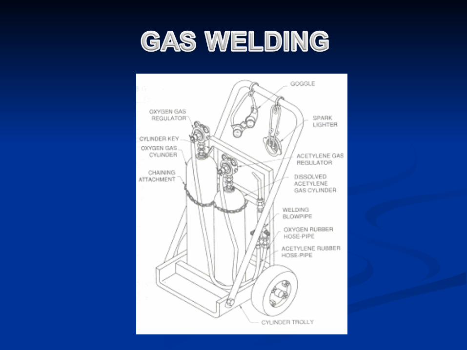
OXY ACETYLENE WELDING OXY ACETYLENE WELDING EQUIPMENTEQUIPMENT
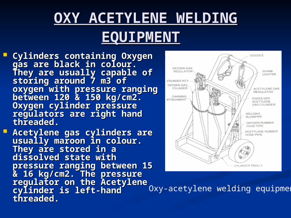
Cylinders containing Oxygen Cylinders containing Oxygen gas are black in colour. They gas are black in colour. They are usually capable of storing are usually capable of storing around 7 m3 of oxygen with around 7 m3 of oxygen with pressure ranging between 120 pressure ranging between 120 & 150 kg/cm2. Oxygen cylinder & 150 kg/cm2. Oxygen cylinder pressure regulators are right pressure regulators are right hand threaded.hand threaded.
Acetylene gas cylinders are Acetylene gas cylinders are usually maroon in colour. They usually maroon in colour. They are stored in a dissolved state are stored in a dissolved state with pressure ranging between with pressure ranging between 15 & 16 kg/cm2. The pressure 15 & 16 kg/cm2. The pressure regulator on the Acetylene regulator on the Acetylene cylinder is left-hand threaded.cylinder is left-hand threaded. Oxy-acetylene welding equipment
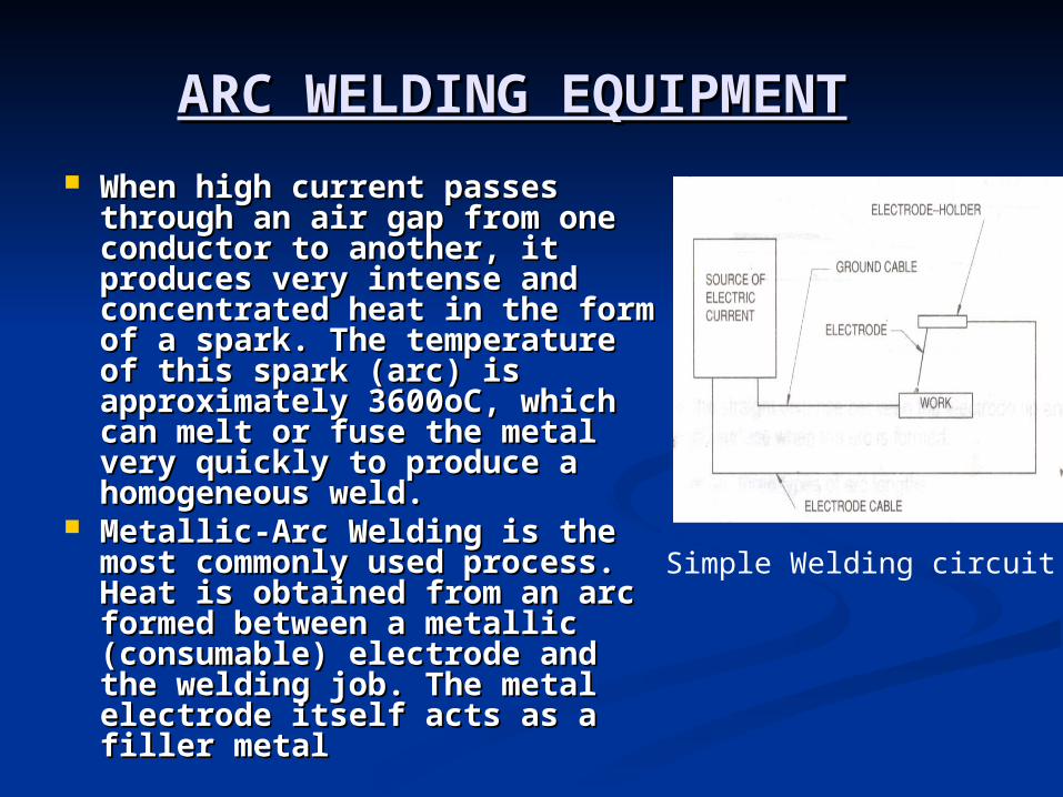
ARC WELDING EQUIPMENTARC WELDING EQUIPMENT When high current passes When high current passes
through an air gap from one through an air gap from one conductor to another, it conductor to another, it produces very intense and produces very intense and concentrated heat in the form of concentrated heat in the form of a spark. The temperature of this a spark. The temperature of this spark (arc) is approximately spark (arc) is approximately 3600oC, which can melt or fuse 3600oC, which can melt or fuse the metal very quickly to the metal very quickly to produce a homogeneous weld.produce a homogeneous weld.
Metallic-Arc Welding is the most Metallic-Arc Welding is the most commonly used process. Heat is commonly used process. Heat is obtained from an arc formed obtained from an arc formed between a metallic (consumable) between a metallic (consumable) electrode and the welding job. electrode and the welding job. The metal electrode itself acts as The metal electrode itself acts as a filler metal a filler metal
Simple Welding circuit
CARBON-ARC WELDING CARBON-ARC WELDING EQUIPMENTEQUIPMENT
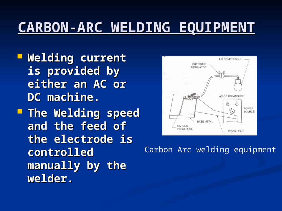
Welding current is Welding current is provided by either an provided by either an AC or DC machine. AC or DC machine.
The Welding speed The Welding speed and the feed of the and the feed of the electrode is electrode is controlled manually controlled manually by the welder. by the welder. Carbon Arc welding equipment
TIG WELDING EQUIPMENTTIG WELDING EQUIPMENT
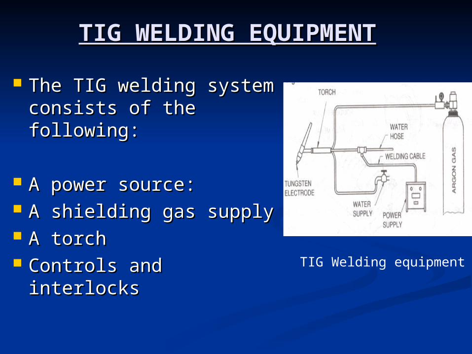
The TIG welding The TIG welding system consists of the system consists of the following:following:
A power source:A power source: A shielding gas supplyA shielding gas supply A torchA torch Controls and interlocksControls and interlocks
TIG Welding equipment
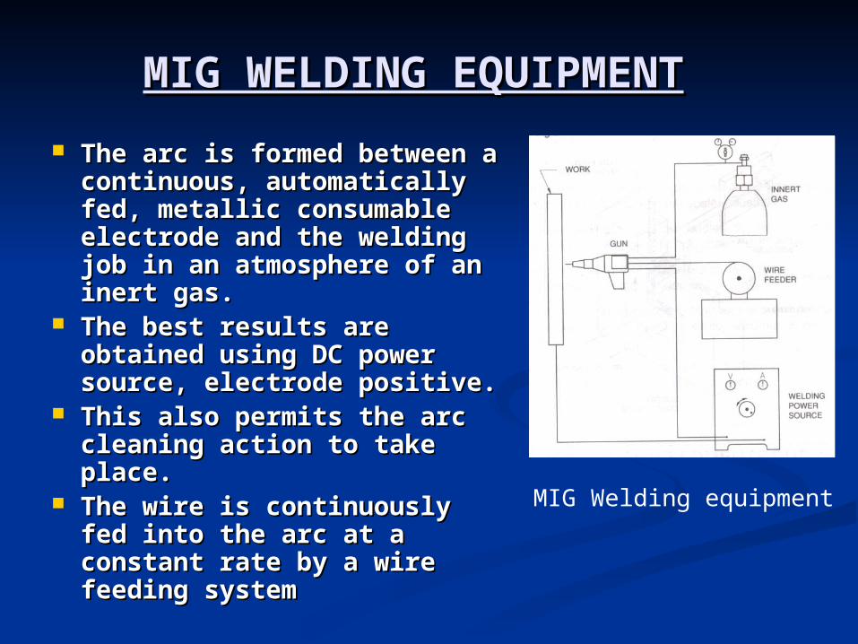
MIG WELDING EQUIPMENTMIG WELDING EQUIPMENT The arc is formed between a The arc is formed between a
continuous, automatically fed, continuous, automatically fed, metallic consumable metallic consumable electrode and the welding job electrode and the welding job in an atmosphere of an inert in an atmosphere of an inert gas.gas.
The best results are obtained The best results are obtained using DC power source, using DC power source, electrode positive.electrode positive.
This also permits the arc This also permits the arc cleaning action to take place. cleaning action to take place.
The wire is continuously fed The wire is continuously fed into the arc at a constant rate into the arc at a constant rate by a wire feeding system by a wire feeding system
MIG Welding equipment
SUBMERGED-ARC WELDING SUBMERGED-ARC WELDING EQUIPMENTEQUIPMENT
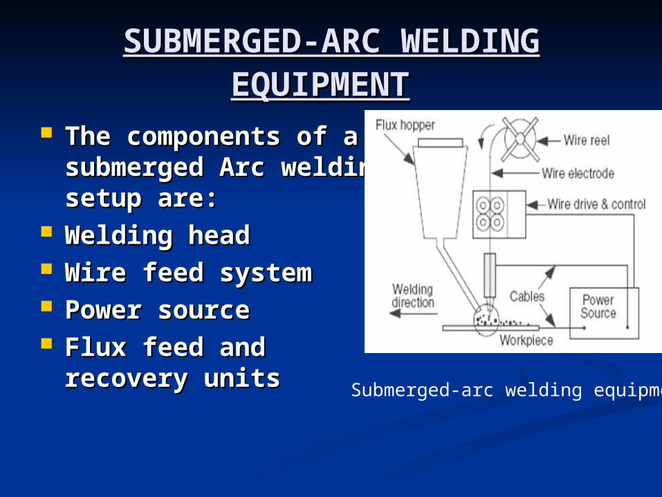
The components of a The components of a submerged Arc welding submerged Arc welding setup are: setup are:
Welding headWelding head Wire feed systemWire feed system Power sourcePower source Flux feed and recovery Flux feed and recovery
unitsunits Submerged-arc welding equipment
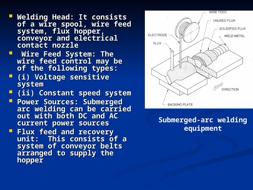
Welding Head: It consists of Welding Head: It consists of a wire spool, wire feed a wire spool, wire feed system, flux hopper, system, flux hopper, conveyor and electrical conveyor and electrical contact nozzlecontact nozzle
Wire Feed System: The Wire Feed System: The wire feed control may be of wire feed control may be of the following types:the following types:
(i) Voltage sensitive system(i) Voltage sensitive system (ii) Constant speed system(ii) Constant speed system Power Sources: Submerged Power Sources: Submerged
arc welding can be carried arc welding can be carried out with both DC and AC out with both DC and AC current power sources current power sources
Flux feed and recovery unit: Flux feed and recovery unit: This consists of a system This consists of a system of conveyor belts arranged of conveyor belts arranged to supply the hopper to supply the hopper
Submerged-arc welding equipment
RETURN TO MAIN CONTENTSRETURN TO MAIN CONTENTS
EXIT SLIDE SHOWEXIT SLIDE SHOW
WELD DESIGNWELD DESIGN
Before an arc is struck on metal, the Before an arc is struck on metal, the product must be designed to serve its product must be designed to serve its purpose, the material chosen and the purpose, the material chosen and the method of welding has to be defined in method of welding has to be defined in detail. detail.
Environmental considerations leading Environmental considerations leading to brittle fracture, creep, corrosion of to brittle fracture, creep, corrosion of welds etc have also to be considered welds etc have also to be considered
PRINCIPLES OF GOOD WELD PRINCIPLES OF GOOD WELD DESIGNDESIGN
Material selection.Material selection.
Weld Process selection.Weld Process selection.
Joint design.Joint design.
Welding Positions Welding Positions
MATERIAL SELECTIONMATERIAL SELECTION
The primary requirement for The primary requirement for selection of any structural material selection of any structural material is its “is its “WeldabilityWeldability”. ”.
Weldability is the capacity of a Weldability is the capacity of a material to be welded, under the material to be welded, under the fabrication conditions imposed, into fabrication conditions imposed, into a specific suitably designed a specific suitably designed structure and to perform structure and to perform satisfactorily in the intended service satisfactorily in the intended service
Weldability encompasses the following:Weldability encompasses the following: (a) Metallurgical compatibility of a (a) Metallurgical compatibility of a
metal or alloy with any specific metal or alloy with any specific welding process. welding process.
(b) Ability of the metal or alloy to be (b) Ability of the metal or alloy to be welded with mechanical soundness.welded with mechanical soundness.
(c) Serviceability of the resulting (c) Serviceability of the resulting welding joint.welding joint.
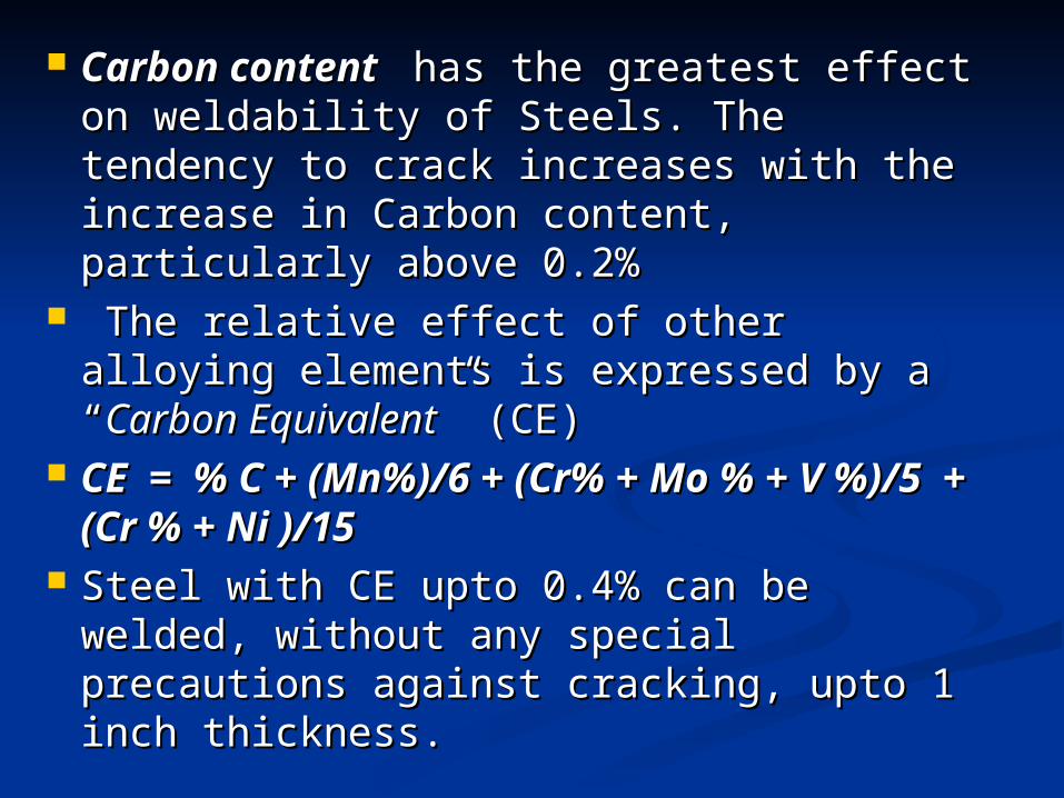
Carbon contentCarbon content has the greatest effect has the greatest effect on weldability of Steels. The tendency to on weldability of Steels. The tendency to crack increases with the increase in crack increases with the increase in Carbon content, particularly above 0.2%Carbon content, particularly above 0.2%
The relative effect of other alloying The relative effect of other alloying elements is expressed by a “elements is expressed by a “Carbon Carbon EquivalentEquivalent” (CE) ” (CE)
CE = % C + (Mn%)/6 + (Cr% + Mo CE = % C + (Mn%)/6 + (Cr% + Mo % + V %)/5 + (Cr % + Ni )/15% + V %)/5 + (Cr % + Ni )/15
Steel with CE upto 0.4% can be welded, Steel with CE upto 0.4% can be welded, without any special precautions against without any special precautions against cracking, upto 1 inch thickness.cracking, upto 1 inch thickness.
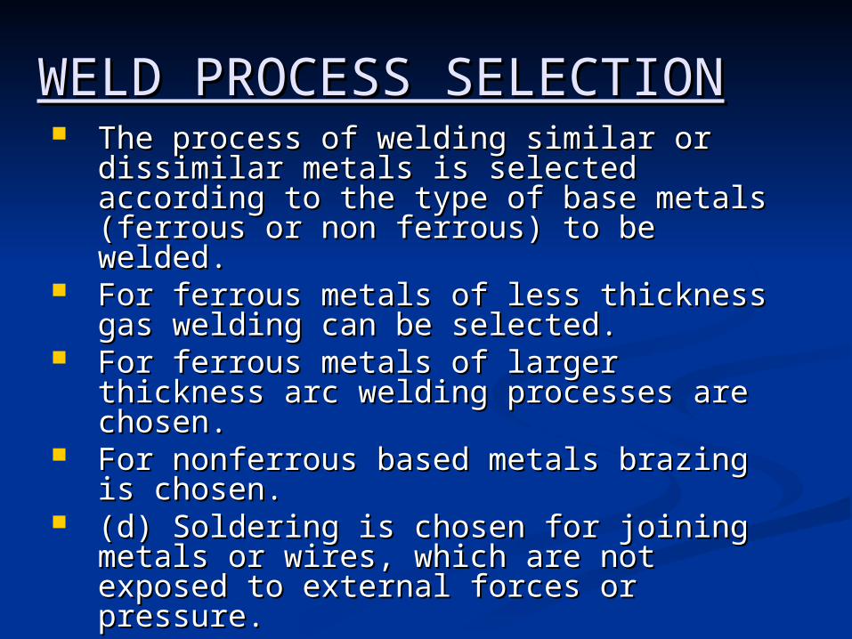
WELD PROCESS WELD PROCESS SELECTIONSELECTION The process of welding similar or The process of welding similar or
dissimilar metals is selected dissimilar metals is selected according to the type of base metals according to the type of base metals (ferrous or non ferrous) to be welded. (ferrous or non ferrous) to be welded.
For ferrous metals of less thickness For ferrous metals of less thickness gas welding can be selected. gas welding can be selected.
For ferrous metals of larger thickness For ferrous metals of larger thickness arc welding processes are chosen. arc welding processes are chosen.
For nonferrous based metals brazing For nonferrous based metals brazing is chosen. is chosen.
(d) Soldering is chosen for joining (d) Soldering is chosen for joining metals or wires, which are not metals or wires, which are not exposed to external forces or exposed to external forces or pressure. pressure.
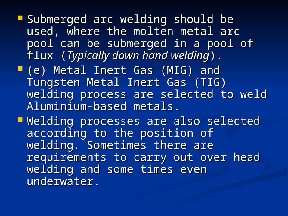
Submerged arc welding should be Submerged arc welding should be used, where the molten metal arc used, where the molten metal arc pool can be submerged in a pool of pool can be submerged in a pool of flux (flux (Typically down hand weldingTypically down hand welding).).
(e) Metal Inert Gas (MIG) and (e) Metal Inert Gas (MIG) and Tungsten Metal Inert Gas (TIG) Tungsten Metal Inert Gas (TIG) welding process are selected to weld welding process are selected to weld Aluminium-based metals. Aluminium-based metals.
Welding processes are also selected Welding processes are also selected according to the position of welding. according to the position of welding. Sometimes there are requirements to Sometimes there are requirements to carry out over head welding and some carry out over head welding and some times even underwater. times even underwater.
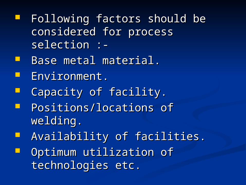
Following factors should be Following factors should be considered for process selection :-considered for process selection :-
Base metal material.Base metal material. Environment.Environment. Capacity of facility.Capacity of facility. Positions/locations of welding.Positions/locations of welding. Availability of facilities.Availability of facilities. Optimum utilization of technologies Optimum utilization of technologies
etc.etc.
WELD JOINT DESIGNWELD JOINT DESIGN::
Selection and preparation of weld joints is Selection and preparation of weld joints is and important step in the fabrication of a and important step in the fabrication of a weldment and is very essential if the welded weldment and is very essential if the welded members are to perform within the load members are to perform within the load service, corrosive atmosphere and safety service, corrosive atmosphere and safety requirements. requirements.
The final product should have sufficient The final product should have sufficient strength to perform well under loaded strength to perform well under loaded conditions and should also be pleasing in conditions and should also be pleasing in appearance.appearance.
The selection of Weld-Joint for a The selection of Weld-Joint for a particular type of weldment depends particular type of weldment depends upon the following factors:-upon the following factors:-
Base-plate thickness.Base-plate thickness. Geometry of structure.Geometry of structure. Magnitude and type of loading.Magnitude and type of loading. Cost of edge preparation.Cost of edge preparation. Number of passes.Number of passes. Electrode consumption and cost of Electrode consumption and cost of
welding.welding. Chances and magnitude of distortion.Chances and magnitude of distortion. Operational ease.Operational ease.
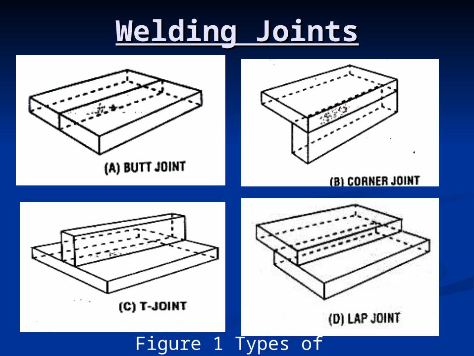
Welding JointsWelding Joints
Figure 1 Types of Weld Joints
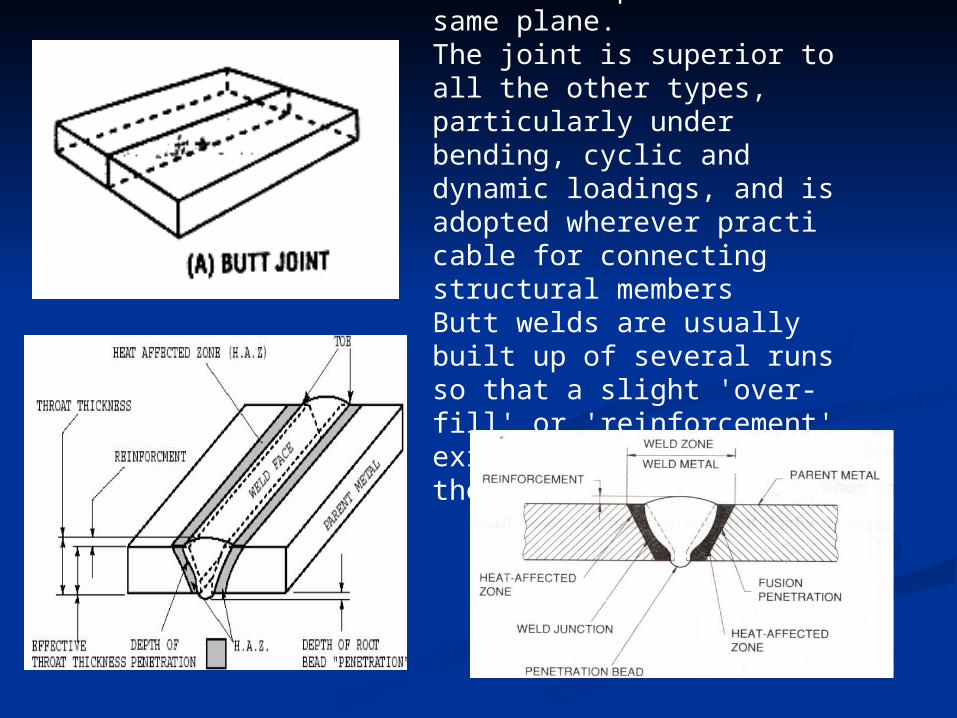
This type of joint is used to connect plates in the same plane. The joint is superior to all the other types, particularly under bending, cyclic and dynamic loadings, and is adopted wherever practi cable for connecting structural members Butt welds are usually built up of several runs so that a slight 'over-fill' or 'reinforcement' exists on both surfaces of the finished weld.
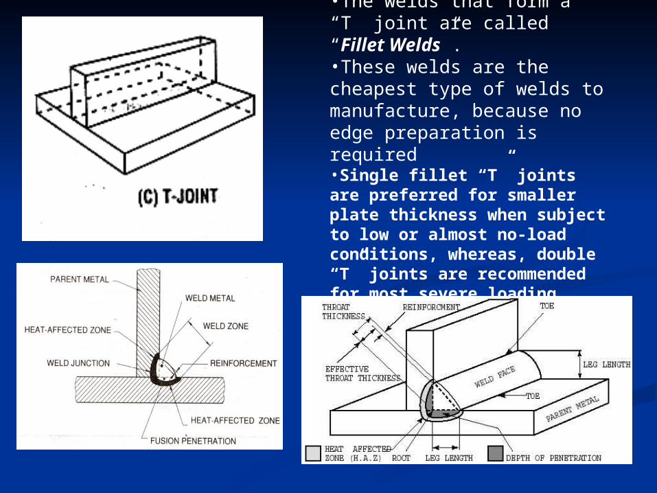
•The welds that form a “T” joint are called “Fillet Welds”. •These welds are the cheapest type of welds to manufacture, because no edge preparation is required •Single fillet “T” joints are preferred for smaller plate thickness when subject to low or almost no-load conditions, whereas, double “T” joints are recommended for most severe loading conditions
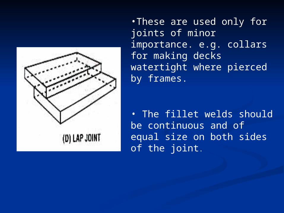
•These are used only for joints of minor importance. e.g. collars for making decks watertight where pierced by frames.
• The fillet welds should be continuous and of equal size on both sides of the joint.
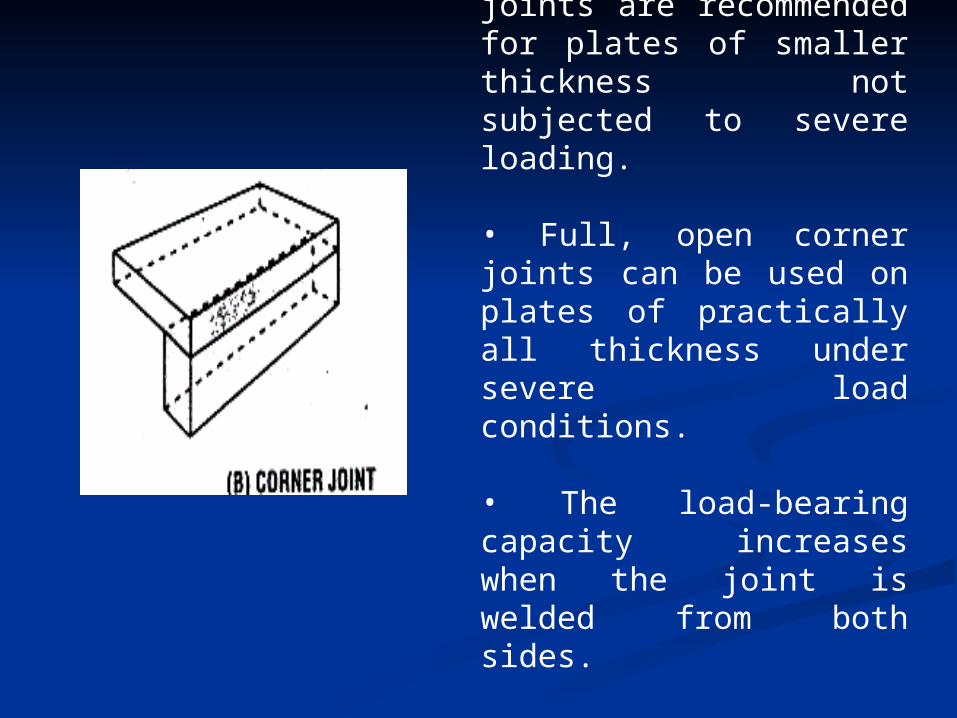
•Closed and half open joints are recommended for plates of smaller thickness not subjected to severe loading.
• Full, open corner joints can be used on plates of practically all thickness under severe load conditions.
• The load-bearing capacity increases when the joint is welded from both sides.
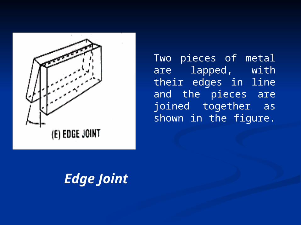
Edge Joint
Two pieces of metal are lapped, with their edges in line and the pieces are joined together as shown in the figure.
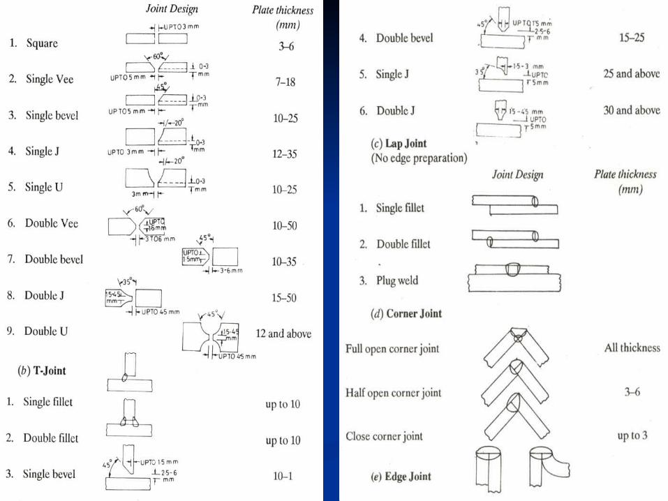
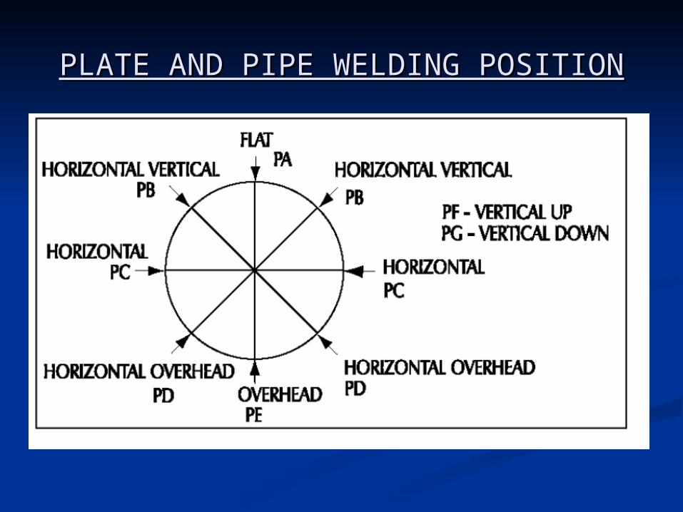
PLATE AND PIPE WELDING PLATE AND PIPE WELDING POSITIONPOSITION
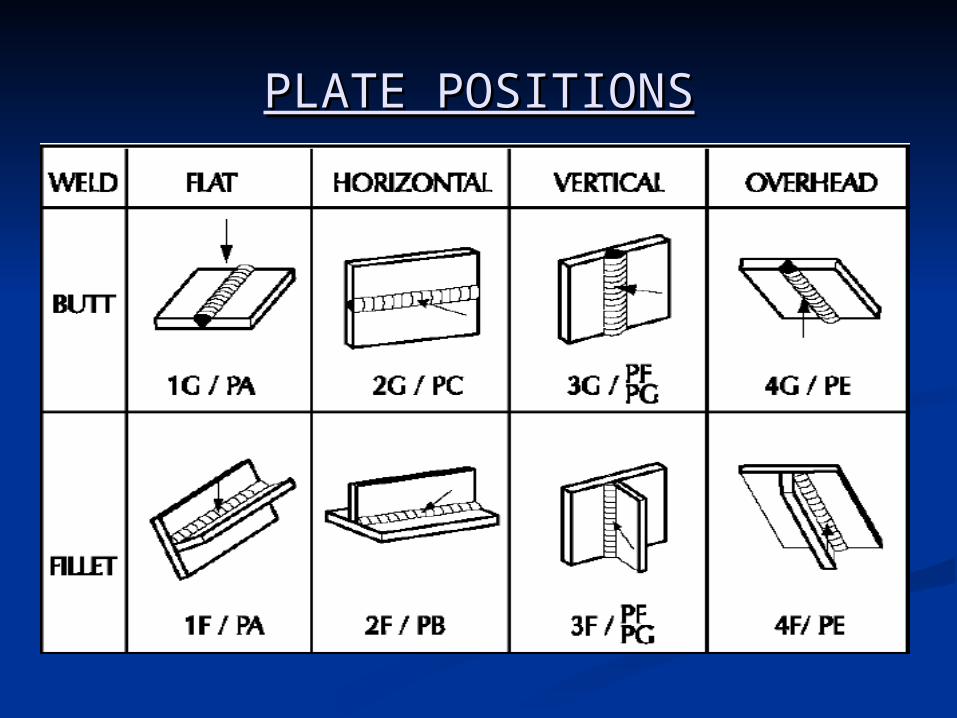
PLATE POSITIONSPLATE POSITIONS
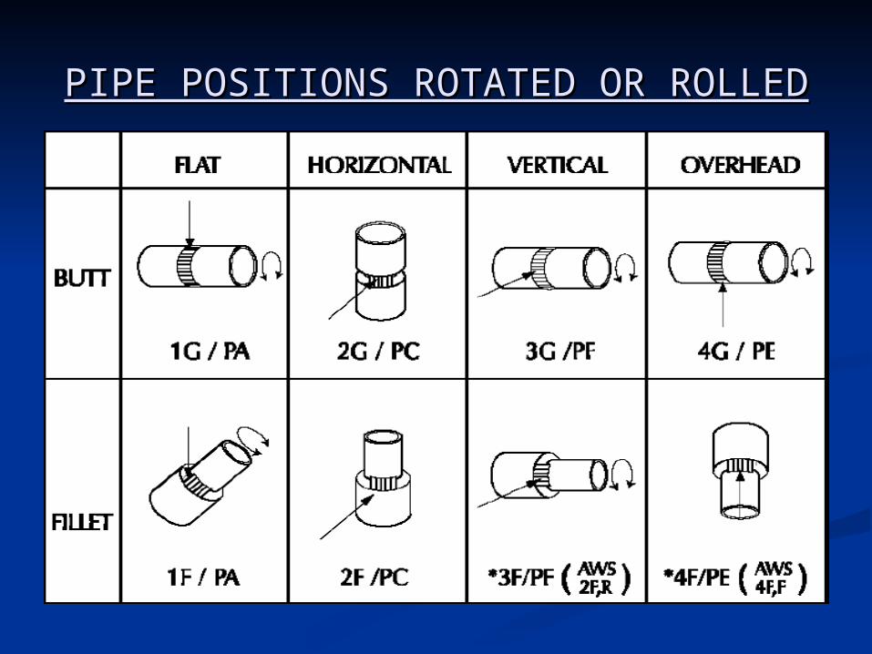
PIPE POSITIONS ROTATED OR PIPE POSITIONS ROTATED OR ROLLEDROLLED
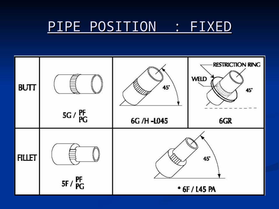
PIPE POSITION : FIXEDPIPE POSITION : FIXED
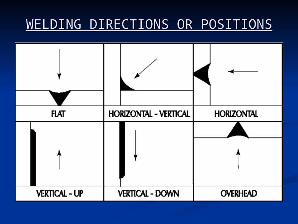
WELDING DIRECTIONS OR WELDING DIRECTIONS OR POSITIONSPOSITIONS

RETURN TO MAIN CONTENTSRETURN TO MAIN CONTENTS
EXIT SLIDE SHOWEXIT SLIDE SHOW

WELD DEFECTSWELD DEFECTS
Need to study weld defects?Need to study weld defects? A defective weldment fails under A defective weldment fails under
service conditions and causes service conditions and causes damage to property and loss of damage to property and loss of human lives. human lives.
This makes it necessary to study This makes it necessary to study defects in weld joints and analyse defects in weld joints and analyse their causes.their causes.
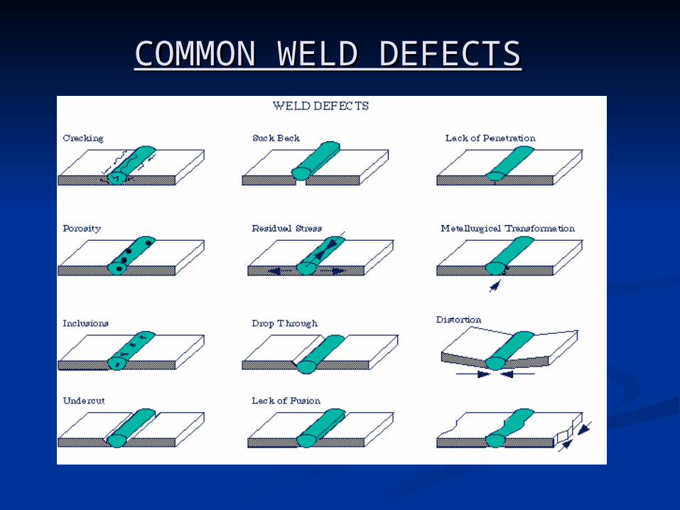
COMMON WELD DEFECTSCOMMON WELD DEFECTS
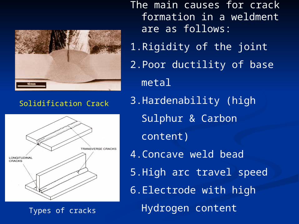
Solidification Crack
The main causes for crack formation in a weldment are as follows:
1. Rigidity of the joint
2. Poor ductility of base metal
3. Hardenability (high Sulphur
& Carbon content)
4. Concave weld bead
5. High arc travel speed
6. Electrode with high
Hydrogen content
Types of cracks
Some remedies to reduce appearance of cracks Some remedies to reduce appearance of cracks are as follows :-are as follows :-
(a) Apply preheat to the base metal.(a) Apply preheat to the base metal. (b) Relieve residual stresses mechanically.(b) Relieve residual stresses mechanically. (c) Minimize shrinkage stresses using back step or (c) Minimize shrinkage stresses using back step or
block welding sequence.block welding sequence. (d) Change weld current and travel speed (to effect (d) Change weld current and travel speed (to effect
slower cooling rate).slower cooling rate). (e) Bake electrodes to remove moisture.(e) Bake electrodes to remove moisture. (f) Reduce root opening; build-up edge with weld (f) Reduce root opening; build-up edge with weld
metal.metal. (g) Increase electrode size for small weld bead, raise (g) Increase electrode size for small weld bead, raise
welding current, and reduce travel speed.welding current, and reduce travel speed. (h) For high sulphur base metal, use filler metal low (h) For high sulphur base metal, use filler metal low
in sulphur.in sulphur. (j) Use of jigs and fixtures. (j) Use of jigs and fixtures. (k) Reduce welding time. (k) Reduce welding time. (l) Weld outward from the centre point.(l) Weld outward from the centre point. (m)Removal of shrinkage forces during or after (m)Removal of shrinkage forces during or after
welding.welding. (n) Breaking down of forge weld mends into sub (n) Breaking down of forge weld mends into sub
assemblies. assemblies.
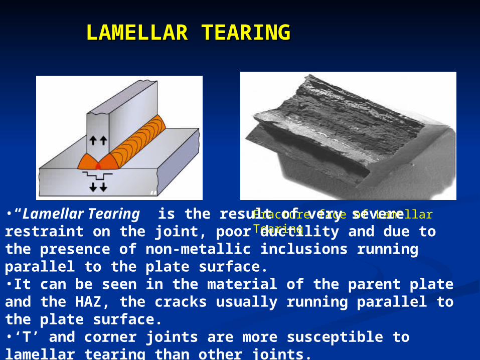
LAMELLAR TEARINGLAMELLAR TEARING
Fracture face of Lamellar Tearing
•“Lamellar Tearing” is the result of very severe restraint on the joint, poor ductility and due to the presence of non-metallic inclusions running parallel to the plate surface. •It can be seen in the material of the parent plate and the HAZ, the cracks usually running parallel to the plate surface.•‘T’ and corner joints are more susceptible to lamellar tearing than other joints.
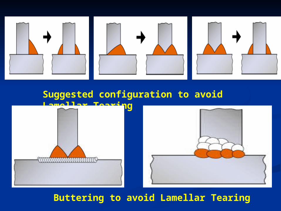
Suggested configuration to avoid Lamellar Tearing
Buttering to avoid Lamellar Tearing
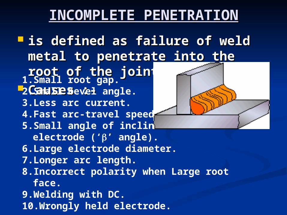
INCOMPLETE PENETRATIONINCOMPLETE PENETRATION
is defined as failure of weld is defined as failure of weld metal to penetrate into the root metal to penetrate into the root of the joint. of the joint.
Causes :-Causes :-1.Small root gap.2.Small bevel angle.3.Less arc current.4.Fast arc-travel speed.5.Small angle of inclination of
electrode (‘’ angle).6.Large electrode diameter.7.Longer arc length.8.Incorrect polarity when Large root
face.9.Welding with DC.10.Wrongly held electrode.
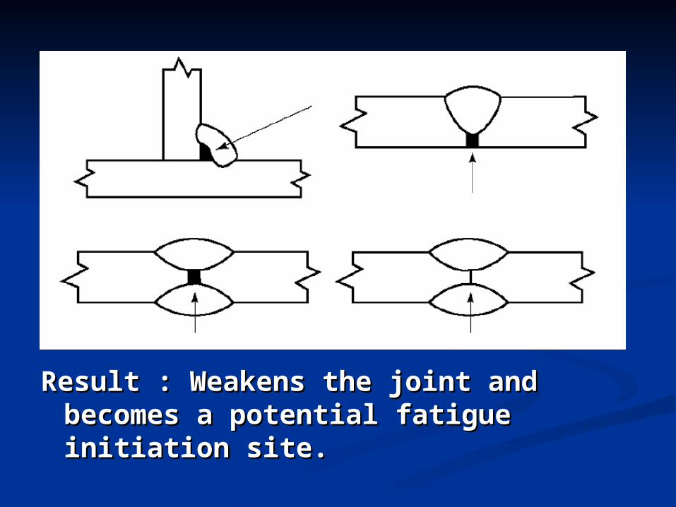
Result : Weakens the joint and Result : Weakens the joint and becomes a potential fatigue becomes a potential fatigue initiation site.initiation site.
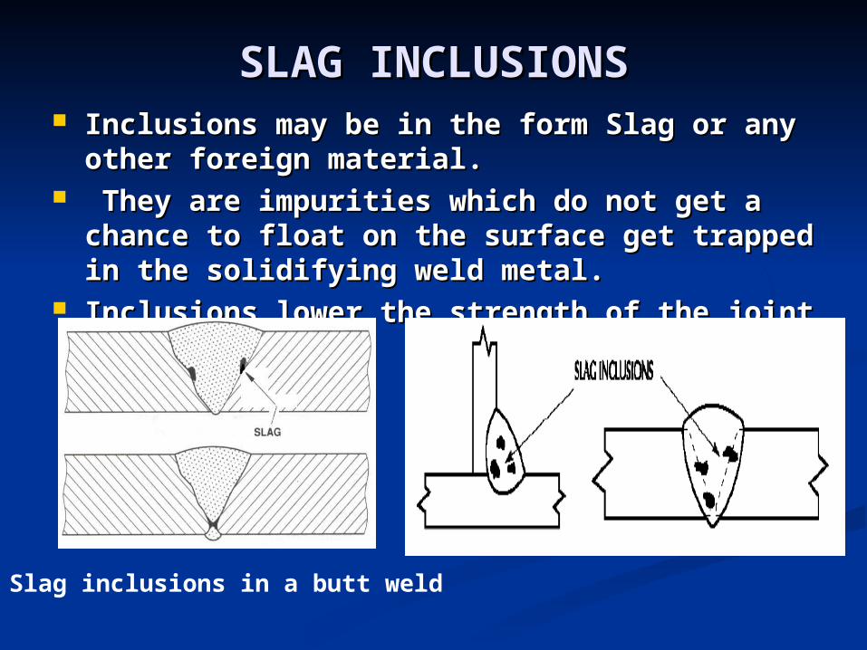
SLAG INCLUSIONSSLAG INCLUSIONS Inclusions may be in the form Slag or any Inclusions may be in the form Slag or any
other foreign material.other foreign material. They are impurities which do not get a They are impurities which do not get a
chance to float on the surface get trapped in chance to float on the surface get trapped in the solidifying weld metal.the solidifying weld metal.
Inclusions lower the strength of the joint Inclusions lower the strength of the joint
Slag inclusions in a butt weld
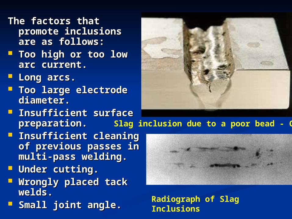
The factors that The factors that promote inclusions promote inclusions are as follows:are as follows:
Too high or too low Too high or too low arc current.arc current.
Long arcs.Long arcs. Too large electrode Too large electrode
diameter.diameter. Insufficient surface Insufficient surface
preparation.preparation. Insufficient cleaning Insufficient cleaning
of previous passes in of previous passes in multi-pass welding.multi-pass welding.
Under cutting.Under cutting. Wrongly placed tack Wrongly placed tack
welds.welds. Small joint angle.Small joint angle.
Slag inclusion due to a poor bead - Convex
Radiograph of Slag Inclusions
POROSITY AND BLOW HOLESPOROSITY AND BLOW HOLES
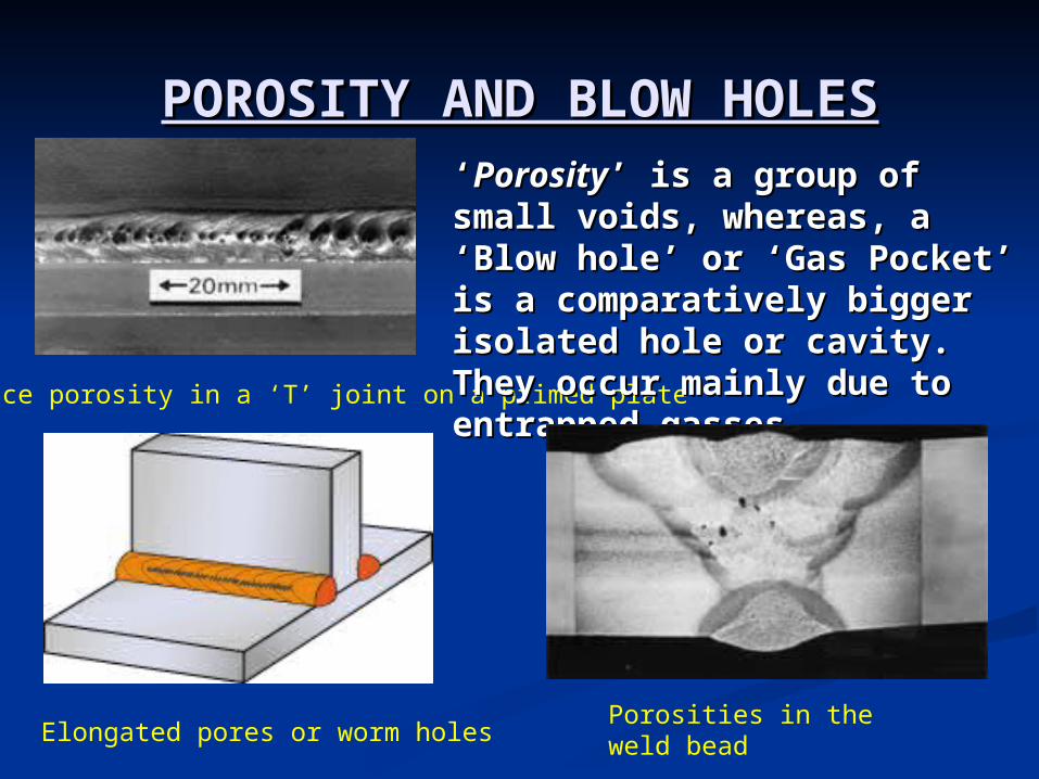
Surface porosity in a ‘T’ joint on a primed plate
‘‘PorosityPorosity’ is a group of small ’ is a group of small voids, whereas, a ‘Blow hole’ voids, whereas, a ‘Blow hole’ or ‘Gas Pocket’ is a or ‘Gas Pocket’ is a comparatively bigger isolated comparatively bigger isolated hole or cavity. They occur hole or cavity. They occur mainly due to entrapped mainly due to entrapped gasses.gasses.
Porosities in the weld beadElongated pores or worm holes
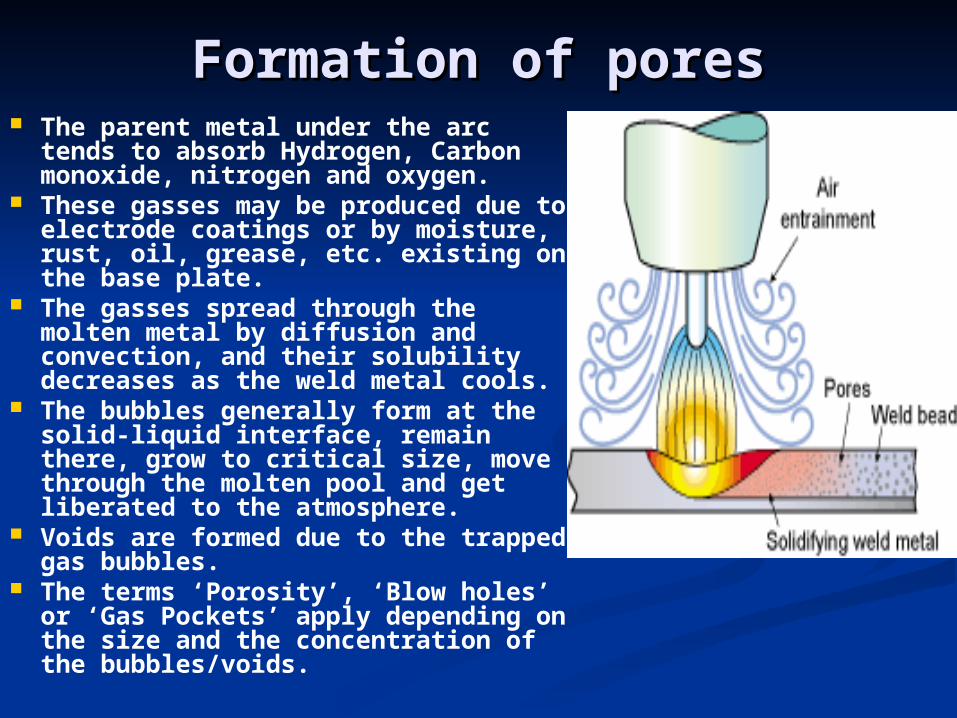
Formation of poresFormation of pores The parent metal under the arc
tends to absorb Hydrogen, Carbon monoxide, nitrogen and oxygen.
These gasses may be produced due to electrode coatings or by moisture, rust, oil, grease, etc. existing on the base plate.
The gasses spread through the molten metal by diffusion and convection, and their solubility decreases as the weld metal cools.
The bubbles generally form at the solid-liquid interface, remain there, grow to critical size, move through the molten pool and get liberated to the atmosphere.
Voids are formed due to the trapped gas bubbles.
The terms ‘Porosity’, ‘Blow holes’ or ‘Gas Pockets’ apply depending on the size and the concentration of the bubbles/voids.
Factors leading to these defects are as Factors leading to these defects are as follows:follows:
Improper electrode (or coating) or Improper electrode (or coating) or damaged/damp coating.damaged/damp coating.
Longer arcs.Longer arcs. Faster arc travel speeds.Faster arc travel speeds. Too high/low currents.Too high/low currents. Incorrect welding techniques.Incorrect welding techniques. Impurities present on the job surface.Impurities present on the job surface. Improper base-metal configuration Improper base-metal configuration
(high ‘S’ or ‘C’ content).(high ‘S’ or ‘C’ content).
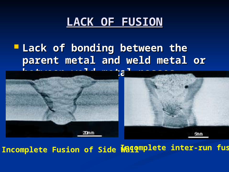
LACK OF FUSIONLACK OF FUSION
Lack of bonding between the Lack of bonding between the parent metal and weld metal or parent metal and weld metal or between weld metal passes.between weld metal passes.
Incomplete Fusion of Side WallIncomplete inter-run fusion
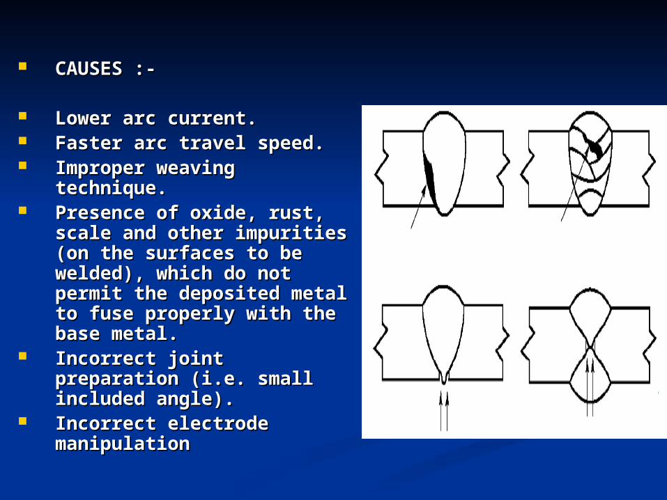
CAUSES :-CAUSES :-
Lower arc current.Lower arc current. Faster arc travel speed.Faster arc travel speed. Improper weaving Improper weaving
technique.technique. Presence of oxide, rust, Presence of oxide, rust,
scale and other impurities scale and other impurities (on the surfaces to be (on the surfaces to be welded), which do not welded), which do not permit the deposited metal permit the deposited metal to fuse properly with the to fuse properly with the base metal.base metal.
Incorrect joint preparation Incorrect joint preparation (i.e. small included angle).(i.e. small included angle).
Incorrect electrode Incorrect electrode manipulation manipulation

Measures to avoid/reduce poor Measures to avoid/reduce poor fusion are:fusion are:
(a) Follow correct welding (a) Follow correct welding procedures.procedures.
(b) Maintain proper electrode (b) Maintain proper electrode position.position.
(c) Reposition work, lower current (c) Reposition work, lower current or increase arc travel speed.or increase arc travel speed.
(d) Clean weld surface prior to (d) Clean weld surface prior to welding.welding.
SPATTERSPATTER
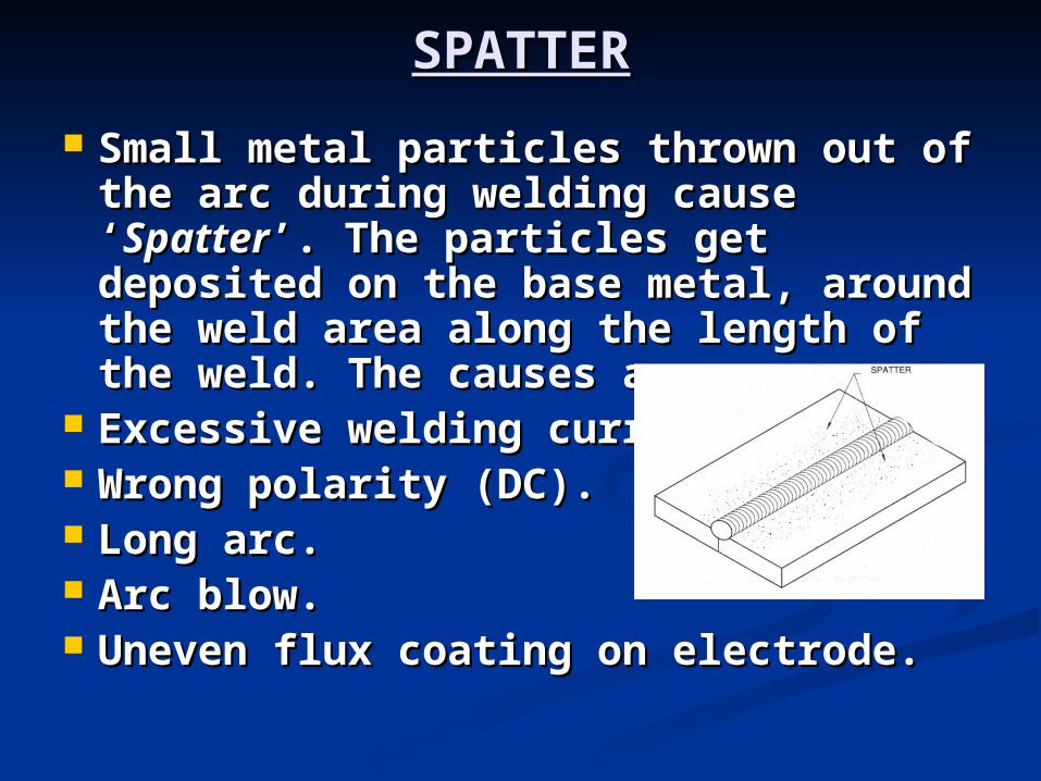
Small metal particles thrown out of Small metal particles thrown out of the arc during welding cause the arc during welding cause ‘‘SpatterSpatter’. The particles get ’. The particles get deposited on the base metal, deposited on the base metal, around the weld area along the around the weld area along the length of the weld. The causes are:length of the weld. The causes are:
Excessive welding current.Excessive welding current. Wrong polarity (DC).Wrong polarity (DC). Long arc.Long arc. Arc blow.Arc blow. Uneven flux coating on electrode. Uneven flux coating on electrode.
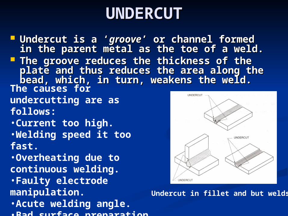
UNDERCUTUNDERCUT Undercut is a ‘Undercut is a ‘groovegroove’ or channel formed in ’ or channel formed in
the parent metal as the toe of a weld. the parent metal as the toe of a weld. The groove reduces the thickness of the The groove reduces the thickness of the
plate and thus reduces the area along the plate and thus reduces the area along the bead, which, in turn, weakens the weld. bead, which, in turn, weakens the weld.
The causes for undercutting are as follows:•Current too high.•Welding speed it too fast.•Overheating due to continuous welding.•Faulty electrode manipulation.•Acute welding angle.•Bad surface preparation.
Undercut in fillet and but welds
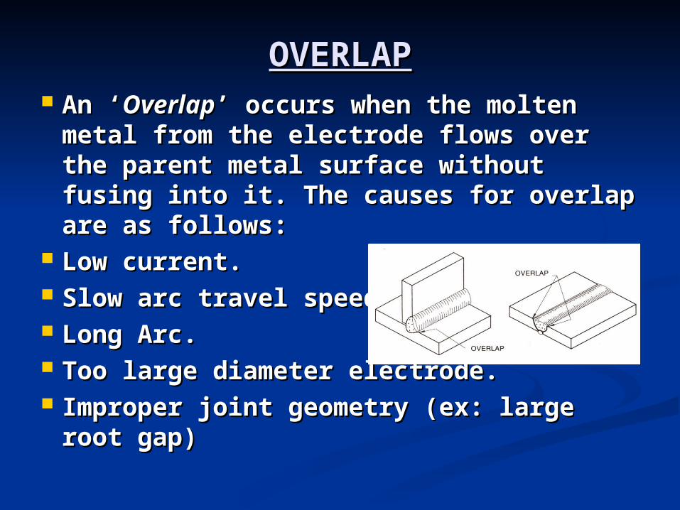
OVERLAPOVERLAP An ‘An ‘OverlapOverlap’ occurs when the molten ’ occurs when the molten
metal from the electrode flows over the metal from the electrode flows over the parent metal surface without fusing parent metal surface without fusing into it. The causes for overlap are as into it. The causes for overlap are as follows:follows:
Low current.Low current. Slow arc travel speed.Slow arc travel speed. Long Arc.Long Arc. Too large diameter electrode.Too large diameter electrode. Improper joint geometry (ex: large root Improper joint geometry (ex: large root
gap) gap)

RETURN TO MAIN CONTENTSRETURN TO MAIN CONTENTS
EXIT SLIDE SHOWEXIT SLIDE SHOW
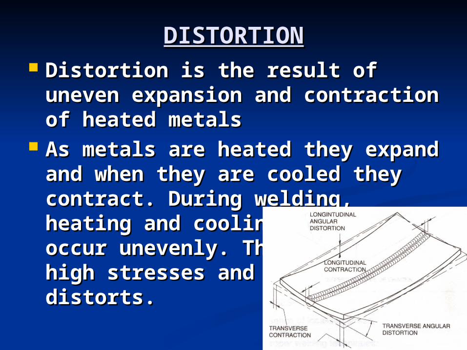
DISTORTIONDISTORTION Distortion is the result of uneven Distortion is the result of uneven
expansion and contraction of expansion and contraction of heated metalsheated metals
As metals are heated they expand As metals are heated they expand and when they are cooled they and when they are cooled they contract. During welding, contract. During welding, heating and cooling of metals heating and cooling of metals occur unevenly. This results in occur unevenly. This results in high stresses and the metal high stresses and the metal distorts.distorts.

TYPES OF DISTORTION:TYPES OF DISTORTION: Longitudinal distortion.Longitudinal distortion.
Transverse distortion.Transverse distortion.
Angular distortion Angular distortion
FACTORS INFLUENCING DISTORTIONFACTORS INFLUENCING DISTORTION
Weld design.Weld design. Parent metal.Parent metal. Edge preparation.Edge preparation. Assembly procedure.Assembly procedure. Welding process.Welding process. Deposition techniques.Deposition techniques. Welding Sequence.Welding Sequence. Unbalanced heating about the Unbalanced heating about the
neutral axis.neutral axis. The restraint imposed The restraint imposed
DISTORTION CONTROLDISTORTION CONTROL Precautions can be taken to Precautions can be taken to
avoid or reduce weld distortions avoid or reduce weld distortions before, duringbefore, during or or after after welding. welding.
The control of distortion before The control of distortion before welding can be facilitated by:-welding can be facilitated by:-
Tack Welding.Tack Welding. Using Jigs, clamps and fixtures.Using Jigs, clamps and fixtures. Ensuring uniform Pre-heating.Ensuring uniform Pre-heating. Pre-setting.Pre-setting.
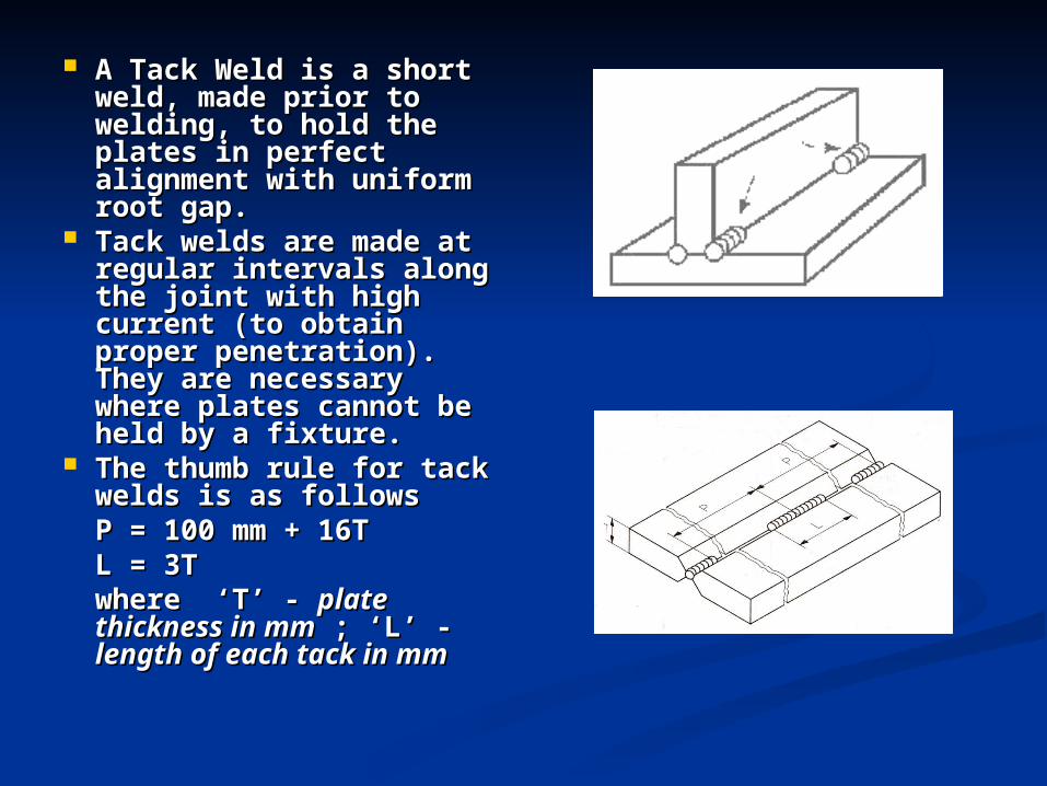
A Tack Weld is a short A Tack Weld is a short weld, made prior to weld, made prior to welding, to hold the welding, to hold the plates in perfect plates in perfect alignment with uniform alignment with uniform root gap. root gap.
Tack welds are made at Tack welds are made at regular intervals along regular intervals along the joint with high the joint with high current (to obtain current (to obtain proper penetration). proper penetration). They are necessary They are necessary where plates cannot be where plates cannot be held by a fixture.held by a fixture.
The thumb rule for tack The thumb rule for tack welds is as followswelds is as follows
P = 100 mm + 16TP = 100 mm + 16TL = 3TL = 3T
where ‘T’ - where ‘T’ - plate plate thickness in mmthickness in mm ; ‘L’ - ; ‘L’ - length of each tack in length of each tack in mmmm
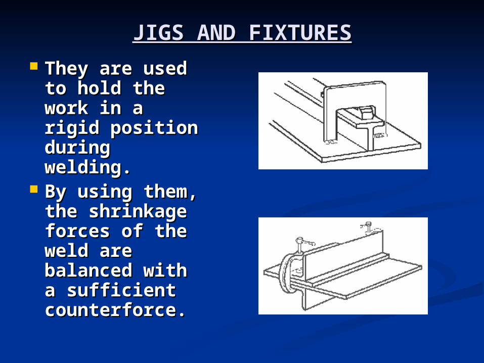
JIGS AND FIXTURESJIGS AND FIXTURES
They are used They are used to hold the to hold the work in a rigid work in a rigid position position during during welding. welding.
By using them, By using them, the shrinkage the shrinkage forces of the forces of the weld are weld are balanced with balanced with a sufficient a sufficient counterforce.counterforce.
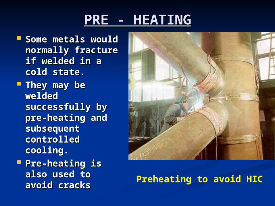
PRE - HEATINGPRE - HEATING Some metals Some metals
would normally would normally fracture if welded fracture if welded in a cold state. in a cold state.
They may be They may be welded welded successfully by successfully by pre-heating and pre-heating and subsequent subsequent controlled controlled cooling. cooling.
Pre-heating is Pre-heating is also used to avoid also used to avoid cracks cracks
Preheating to avoid HIC
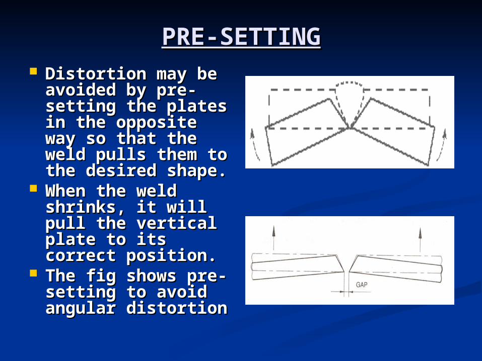
PRE-SETTINGPRE-SETTING Distortion may be Distortion may be
avoided by pre-avoided by pre-setting the plates setting the plates in the opposite in the opposite way so that the way so that the weld pulls them to weld pulls them to the desired shape. the desired shape.
When the weld When the weld shrinks, it will pull shrinks, it will pull the vertical plate the vertical plate to its correct to its correct position. position.
The fig shows pre-The fig shows pre-setting to avoid setting to avoid angular distortion angular distortion
DURING WELDINGDURING WELDING
Back-step welding.Back-step welding.
Intermittent “Intermittent “ChainChain”” & & ““StaggeredStaggered” ”
welding.welding.
Planned wandering method.Planned wandering method.
A correct welding procedure to A correct welding procedure to
reduce the size of the weld beads.reduce the size of the weld beads.
Excessive Welding should be avoided.Excessive Welding should be avoided.
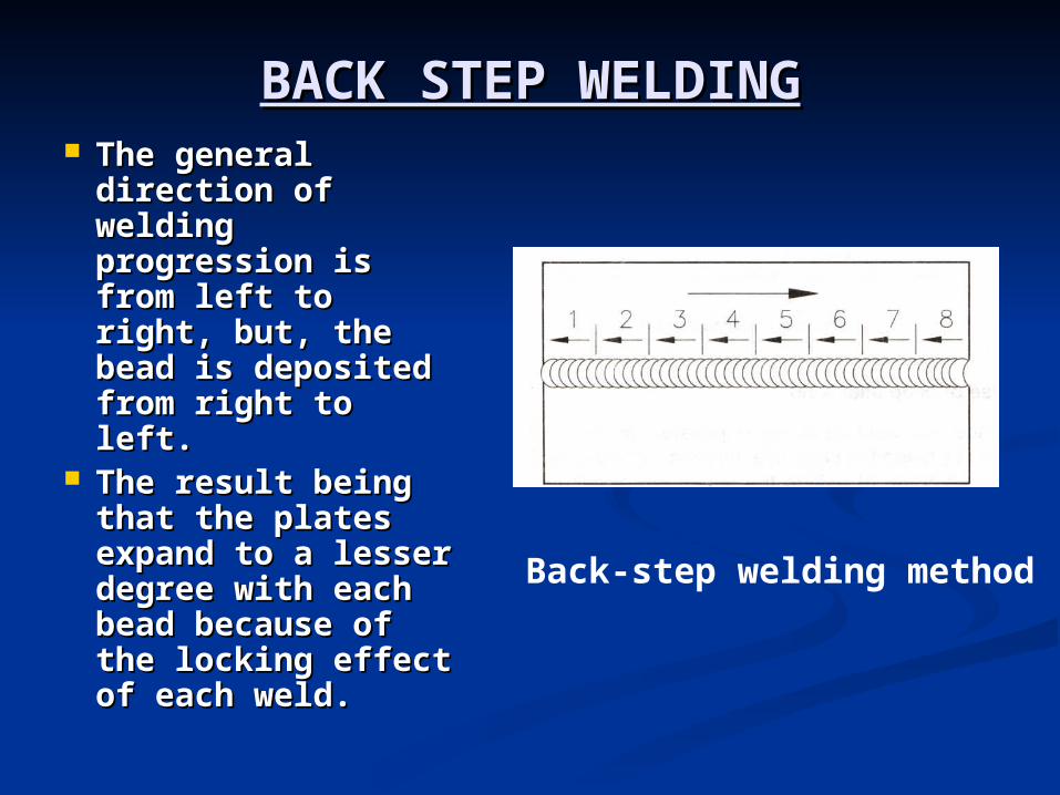
BACK STEP WELDINGBACK STEP WELDING The general The general
direction of direction of welding welding progression is progression is from left to right, from left to right, but, the bead is but, the bead is deposited from deposited from right to left. right to left.
The result being The result being that the plates that the plates expand to a expand to a lesser degree lesser degree with each bead with each bead because of the because of the locking effect of locking effect of each weld. each weld.
Back-step welding method
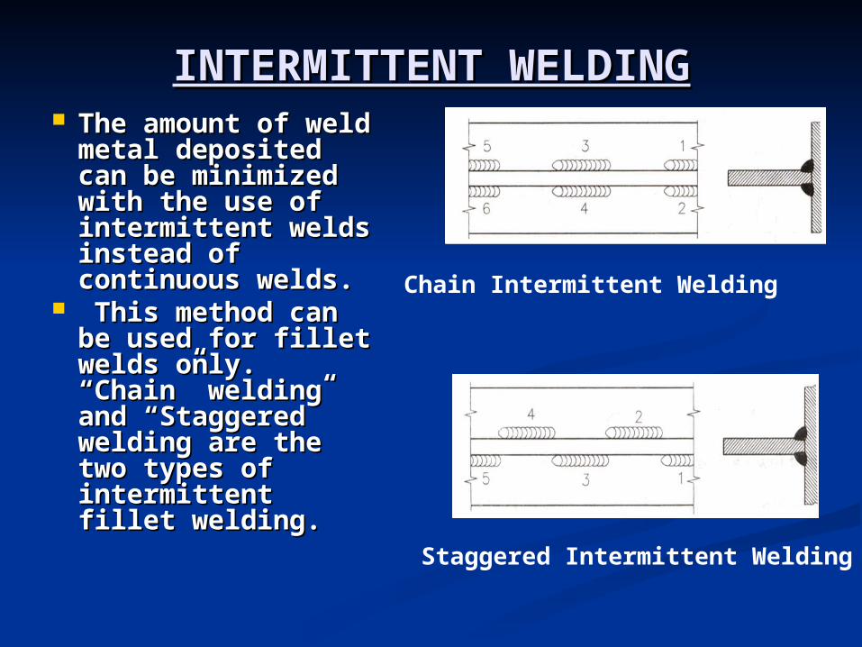
INTERMITTENT WELDINGINTERMITTENT WELDING The amount of The amount of
weld metal weld metal deposited can be deposited can be minimized with minimized with the use of the use of intermittent intermittent welds instead of welds instead of continuous welds.continuous welds.
This method can This method can be used for fillet be used for fillet welds only. welds only. “Chain” welding “Chain” welding and “Staggered” and “Staggered” welding are the welding are the two types of two types of intermittent fillet intermittent fillet welding. welding.
Chain Intermittent Welding
Staggered Intermittent Welding
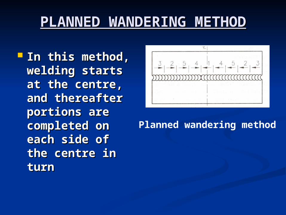
PLANNED WANDERING PLANNED WANDERING METHODMETHOD
In this method, In this method, welding starts welding starts at the centre, at the centre, and thereafter and thereafter portions are portions are completed on completed on each side of the each side of the centre in turncentre in turn
Planned wandering method
AFTER WELDINGAFTER WELDING
The control of distortion after The control of distortion after welding can be facilitated by the welding can be facilitated by the following:-following:-
Slow cooling.Slow cooling. Flame straightening or contra Flame straightening or contra
heating.heating. Annealing.Annealing. Stress relieving.Stress relieving. Normalising.Normalising. Mechanical straightening Mechanical straightening
TIPS TO AVOID DISTORTION TIPS TO AVOID DISTORTION It is possible to reduce the effect of It is possible to reduce the effect of
shrinkage-force by correct edge shrinkage-force by correct edge preparation. This will ensure proper fusion preparation. This will ensure proper fusion at the root of the weld with a minimum of at the root of the weld with a minimum of weld metal.weld metal.
The correct welding procedure used a The correct welding procedure used a greater number of welded runs positioned greater number of welded runs positioned to refine the grain size of the weld metal in to refine the grain size of the weld metal in the previous layer.the previous layer.
A small number if heavy runs will cause A small number if heavy runs will cause more distortion due to the greater heat more distortion due to the greater heat input, and the contraction stresses set up input, and the contraction stresses set up by the cooling of the larger deposit of weld by the cooling of the larger deposit of weld metal. metal.

RETURN TO MAIN CONTENTSRETURN TO MAIN CONTENTS
EXIT SLIDE SHOWEXIT SLIDE SHOW
INSPECTION & NON-INSPECTION & NON-DESTRUCTIVE TESTING OF DESTRUCTIVE TESTING OF
WELDSWELDS Welded joints in a structure are expected to Welded joints in a structure are expected to
possess certain service-related capabilities. possess certain service-related capabilities. They are required to carry loadings of They are required to carry loadings of
various types in which the weld is subjected various types in which the weld is subjected to stress of either a simple or complex to stress of either a simple or complex character. character.
Moreover, a finished weld is not always as Moreover, a finished weld is not always as good as or bad as it may appear to be on its good as or bad as it may appear to be on its surface. Hence, it is necessary to inspect a surface. Hence, it is necessary to inspect a weld-job on completion. weld-job on completion.
The purpose of inspection is to locate and The purpose of inspection is to locate and determine the type of fault, quality of joint determine the type of fault, quality of joint and quality of workmanship and quality of workmanship
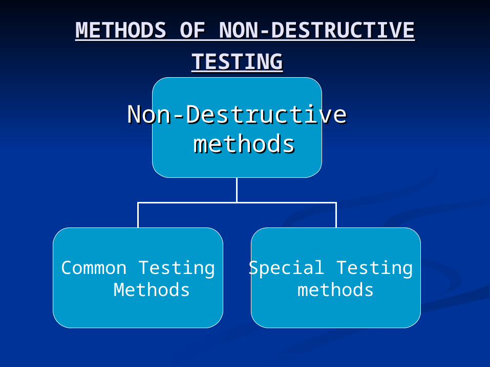
METHODS OF NON-METHODS OF NON-
DESTRUCTIVE TESTINGDESTRUCTIVE TESTING
Non-DestructiveNon-Destructive methodsmethods
Common TestingMethods
Special Testing methods
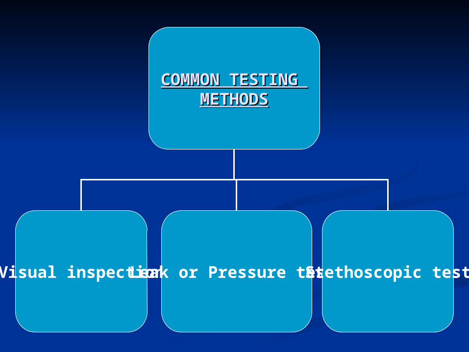
COMMON TESTING COMMON TESTING METHODSMETHODS
Visual inspectionLeak or Pressure test Stethoscopic test
VISUAL INSPECTIONVISUAL INSPECTION
It is the simplest, fastest, the most It is the simplest, fastest, the most economical and most commonly economical and most commonly used method for detecting defects used method for detecting defects on the surface of the weld.on the surface of the weld.
Visual Inspection may be carried out Visual Inspection may be carried out in three stages:in three stages:
(i) Before welding (i) Before welding (ii) During welding(ii) During welding (iii) After welding(iii) After welding
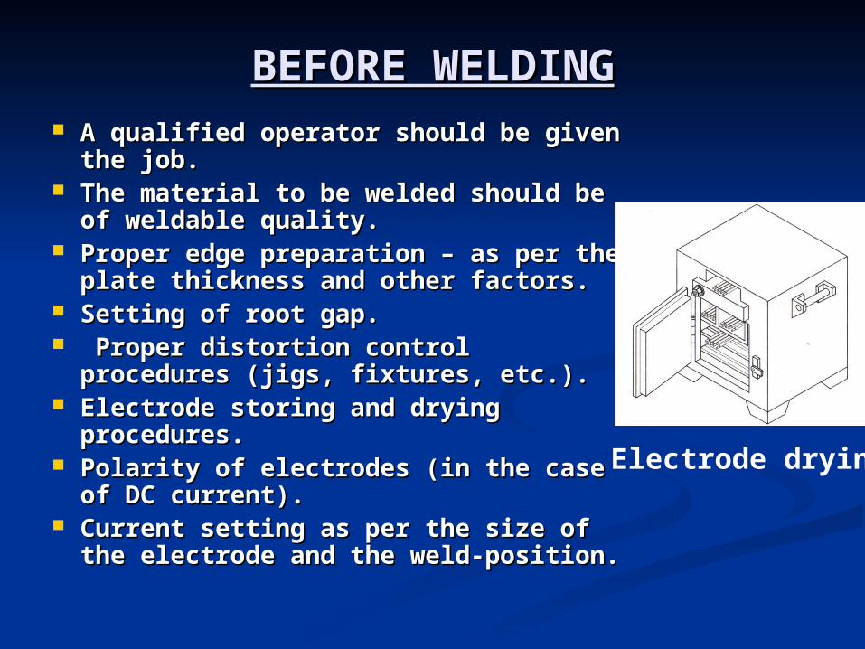
BEFORE WELDINGBEFORE WELDING A qualified operator should be given A qualified operator should be given
the job.the job. The material to be welded should be The material to be welded should be
of weldable quality.of weldable quality. Proper edge preparation – as per the Proper edge preparation – as per the
plate thickness and other factors.plate thickness and other factors. Setting of root gap.Setting of root gap. Proper distortion control procedures Proper distortion control procedures
(jigs, fixtures, etc.).(jigs, fixtures, etc.). Electrode storing and drying Electrode storing and drying
procedures.procedures. Polarity of electrodes (in the case of Polarity of electrodes (in the case of
DC current).DC current). Current setting as per the size of the Current setting as per the size of the
electrode and the weld-position.electrode and the weld-position.
Electrode drying
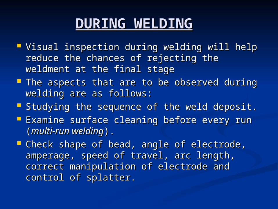
DURING WELDINGDURING WELDING Visual inspection during welding will help Visual inspection during welding will help
reduce the chances of rejecting the weldment reduce the chances of rejecting the weldment at the final stage at the final stage
The aspects that are to be observed during The aspects that are to be observed during welding are as follows:welding are as follows:
Studying the sequence of the weld deposit.Studying the sequence of the weld deposit. Examine surface cleaning before every run Examine surface cleaning before every run
((multi-run weldingmulti-run welding).). Check shape of bead, angle of electrode, Check shape of bead, angle of electrode,
amperage, speed of travel, arc length, correct amperage, speed of travel, arc length, correct manipulation of electrode and control of manipulation of electrode and control of splatter.splatter.
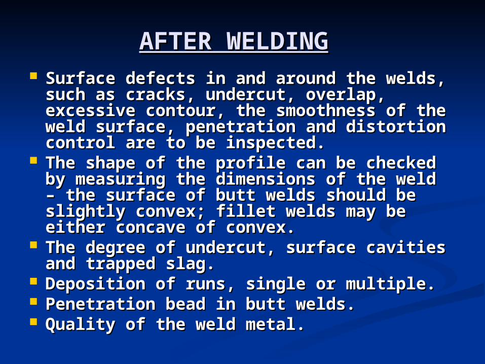
AFTER WELDINGAFTER WELDING Surface defects in and around the welds, Surface defects in and around the welds,
such as cracks, undercut, overlap, such as cracks, undercut, overlap, excessive contour, the smoothness of the excessive contour, the smoothness of the weld surface, penetration and distortion weld surface, penetration and distortion control are to be inspected.control are to be inspected.
The shape of the profile can be checked The shape of the profile can be checked by measuring the dimensions of the weld by measuring the dimensions of the weld – the surface of butt welds should be – the surface of butt welds should be slightly convex; fillet welds may be either slightly convex; fillet welds may be either concave of convex.concave of convex.
The degree of undercut, surface cavities The degree of undercut, surface cavities and trapped slag.and trapped slag.
Deposition of runs, single or multiple.Deposition of runs, single or multiple. Penetration bead in butt welds.Penetration bead in butt welds. Quality of the weld metal.Quality of the weld metal.
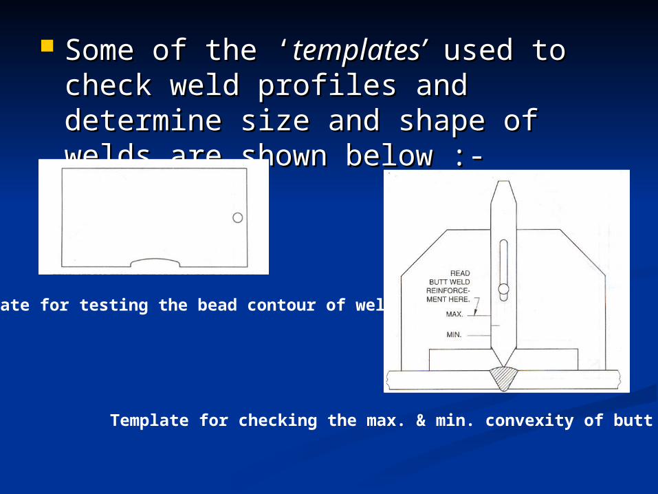
Some of the ‘Some of the ‘templates’templates’ used to used to check weld profiles and determine check weld profiles and determine size and shape of welds are shown size and shape of welds are shown below :-below :-
Template for testing the bead contour of welds
Template for checking the max. & min. convexity of butt welds
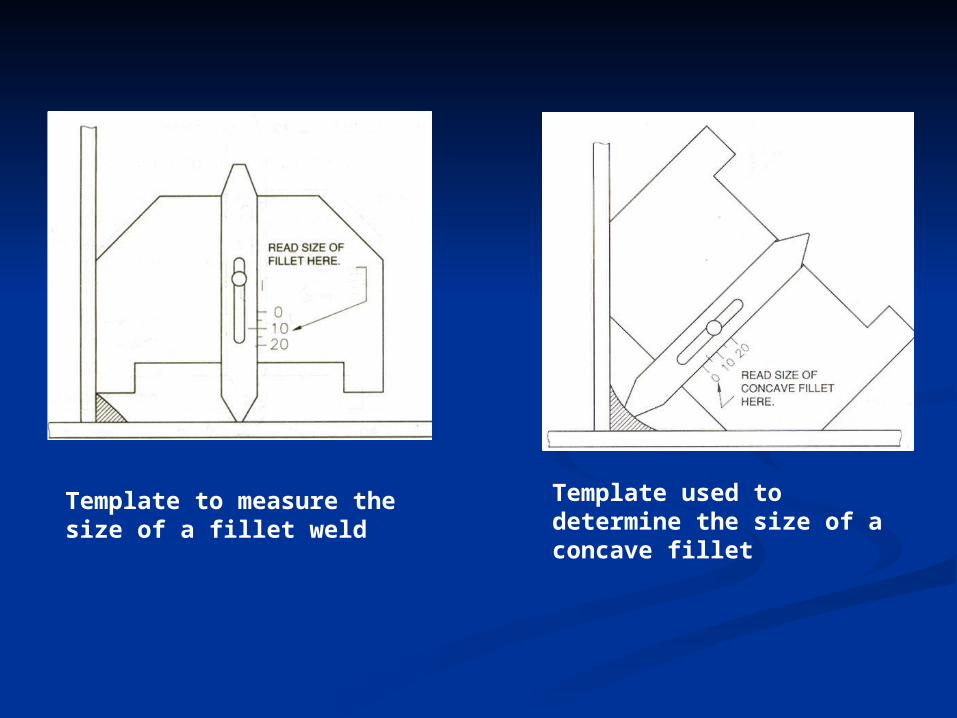
Template to measure the size of a fillet weld
Template used to determine the size of a concave fillet
LEAK OR PRESSURE TESTSLEAK OR PRESSURE TESTS This test is used to test welded pressure This test is used to test welded pressure
vessels, tanks and pipelines for leaks. vessels, tanks and pipelines for leaks. The welded vessel is sealed and The welded vessel is sealed and
subjected to internal pressure using air, subjected to internal pressure using air, water or kerosene. The internal pressure water or kerosene. The internal pressure built-up depends on the working built-up depends on the working pressure of the joint, generally, twice the pressure of the joint, generally, twice the working pressure of the vessel.working pressure of the vessel.
Any drop in pressure would indicate a Any drop in pressure would indicate a leak or leaks. leak or leaks.
Soap solution may be applied to check Soap solution may be applied to check for leaks in an Air-pressure test.for leaks in an Air-pressure test.
STETHOSCOPIC TEST:STETHOSCOPIC TEST: The principle of this test is that a The principle of this test is that a
defect-free weld metal gives a defect-free weld metal gives a good ringing sound when struck good ringing sound when struck with a hammer, whereas that with a hammer, whereas that with defects gives a flat sound. with defects gives a flat sound.
An ordinary physician’s An ordinary physician’s stethoscope and a hammer may stethoscope and a hammer may be used to magnify and identify be used to magnify and identify the sound the sound
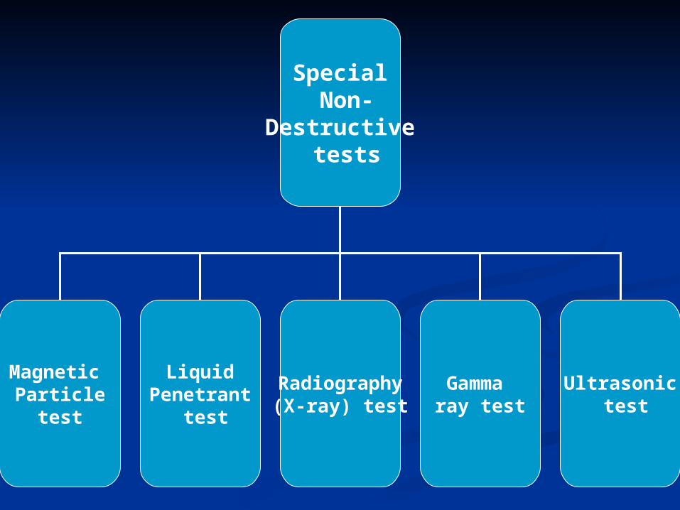
Special Non-
Destructive tests
Magnetic Particle
test
LiquidPenetrant
test
Ultrasonic test
Radiography(X-ray) test
Gamma ray test
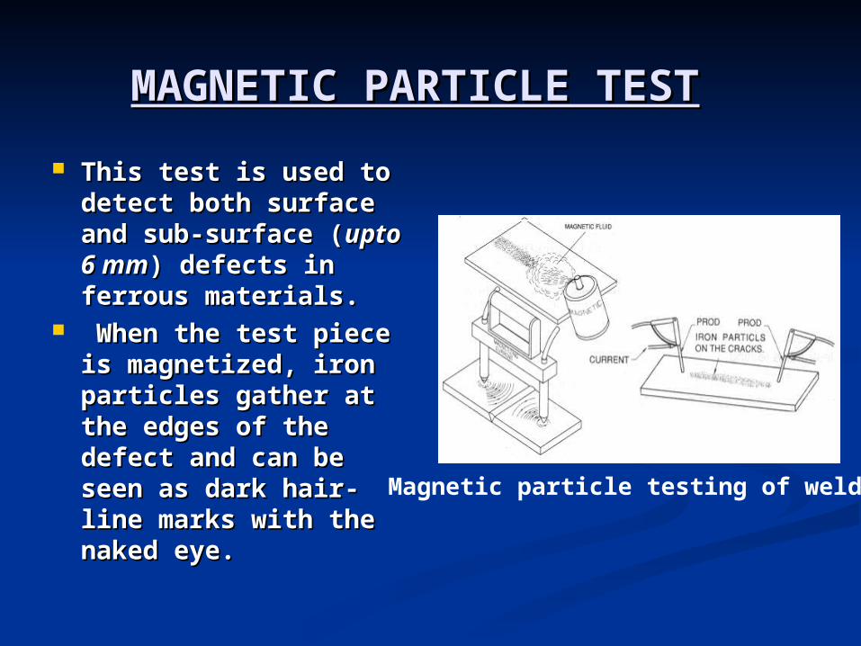
MAGNETIC PARTICLE TESTMAGNETIC PARTICLE TEST This test is used to This test is used to
detect both surface detect both surface and sub-surface and sub-surface ((upto 6 mmupto 6 mm) defects ) defects in ferrous materials.in ferrous materials.
When the test piece When the test piece is magnetized, iron is magnetized, iron particles gather at particles gather at the edges of the the edges of the defect and can be defect and can be seen as dark hair-line seen as dark hair-line marks with the naked marks with the naked eye. eye.
Magnetic particle testing of welds
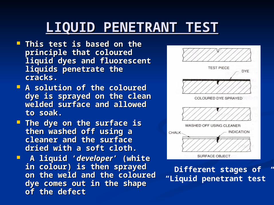
LIQUID PENETRANT TESTLIQUID PENETRANT TEST This test is based on the This test is based on the
principle that coloured principle that coloured liquid dyes and fluorescent liquid dyes and fluorescent liquids penetrate the cracks. liquids penetrate the cracks.
A solution of the coloured A solution of the coloured dye is sprayed on the clean dye is sprayed on the clean welded surface and allowed welded surface and allowed to soak. to soak.
The dye on the surface is The dye on the surface is then washed off using a then washed off using a cleaner and the surface cleaner and the surface dried with a soft cloth.dried with a soft cloth.
A liquid ‘A liquid ‘developerdeveloper’ (white ’ (white in colour) is then sprayed on in colour) is then sprayed on the weld and the coloured the weld and the coloured dye comes out in the shape dye comes out in the shape of the defect of the defect
Different stages of “Liquid penetrant test”
RADIOGRAPHY (X-RAY/GAMMA RADIOGRAPHY (X-RAY/GAMMA
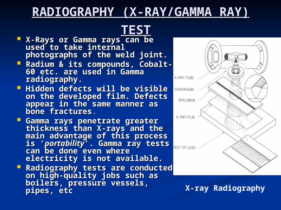
RAY) TESTRAY) TEST X-Rays or Gamma rays can be X-Rays or Gamma rays can be
used to take internal used to take internal photographs of the weld joint. photographs of the weld joint.
Radium & its compounds, Radium & its compounds, Cobalt-60 etc. are used in Cobalt-60 etc. are used in Gamma radiography. Gamma radiography.
Hidden defects will be visible on Hidden defects will be visible on the developed film. Defects the developed film. Defects appear in the same manner as appear in the same manner as bone fracturesbone fractures..
Gamma rays penetrate greater Gamma rays penetrate greater thickness than X-rays and the thickness than X-rays and the main advantage of this process main advantage of this process is ‘is ‘portabilityportability’. Gamma ray tests ’. Gamma ray tests can be done even where can be done even where electricity is not available. electricity is not available.
Radiography tests are Radiography tests are conducted on high-quality jobs conducted on high-quality jobs such as boilers, pressure such as boilers, pressure vessels, pipes, etcvessels, pipes, etc
X-ray Radiography
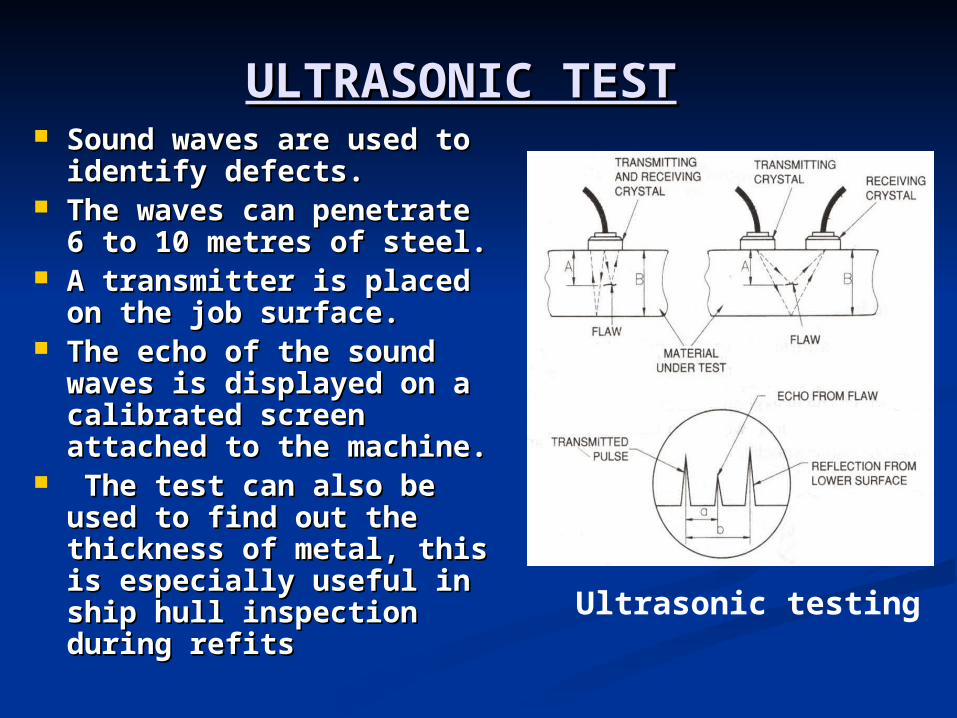
ULTRASONIC TESTULTRASONIC TEST Sound waves are used to Sound waves are used to
identify defects. identify defects. The waves can penetrate The waves can penetrate
6 to 10 metres of steel. 6 to 10 metres of steel. A transmitter is placed A transmitter is placed
on the job surface. on the job surface. The echo of the sound The echo of the sound
waves is displayed on a waves is displayed on a calibrated screen calibrated screen attached to the machine.attached to the machine.
The test can also be The test can also be used to find out the used to find out the thickness of metal, this thickness of metal, this is especially useful in is especially useful in ship hull inspection ship hull inspection during refits during refits
Ultrasonic testing

RETURN TO MAIN CONTENTSRETURN TO MAIN CONTENTS
EXIT SLIDE SHOWEXIT SLIDE SHOW
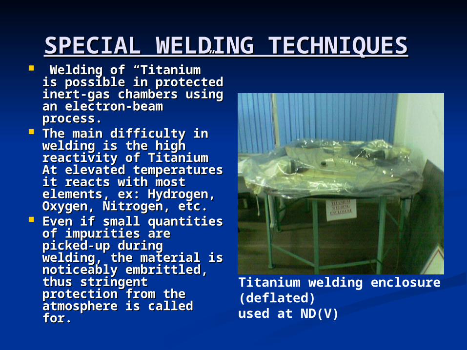
SPECIAL WELDING SPECIAL WELDING TECHNIQUESTECHNIQUES Welding of “Titanium” Welding of “Titanium”
is possible in protected is possible in protected inert-gas chambers inert-gas chambers using an electron-beam using an electron-beam process.process.
The main difficulty in The main difficulty in welding is the high welding is the high reactivity of Titanium At reactivity of Titanium At elevated temperatures it elevated temperatures it reacts with most reacts with most elements, ex: Hydrogen, elements, ex: Hydrogen, Oxygen, Nitrogen, etc. Oxygen, Nitrogen, etc.
Even if small quantities Even if small quantities of impurities are picked-of impurities are picked-up during welding, the up during welding, the material is noticeably material is noticeably embrittled, thus embrittled, thus stringent protection stringent protection from the atmosphere is from the atmosphere is called for. called for.
Titanium welding enclosure (deflated)used at ND(V)
The purity of the inert gas used must The purity of the inert gas used must be at least 99.95%. Argon shielding be at least 99.95%. Argon shielding must be provided till the HAZ has must be provided till the HAZ has cooled to below 300°C. The cooled to below 300°C. The recommended gas-flow rate is 3 to 5 recommended gas-flow rate is 3 to 5 litres per min and the arc length should litres per min and the arc length should be held as short as possible.be held as short as possible.
If it is not possible to provide a If it is not possible to provide a protective chamber, effective protective chamber, effective protection can be obtained by providing protection can be obtained by providing argon, not only with the welding torch argon, not only with the welding torch but also on the trailing side through a but also on the trailing side through a separate feed-tube & nozzle separate feed-tube & nozzle arrangement attached to the torch.arrangement attached to the torch.
Gas should also be supplied on the Gas should also be supplied on the underside through a longitudinal underside through a longitudinal groove in a copper backinggroove in a copper backing..
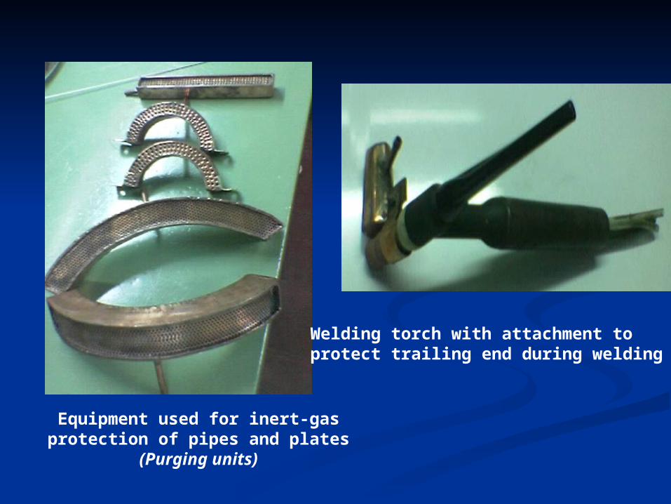
Equipment used for inert-gas protection of pipes and plates
(Purging units)
Welding torch with attachment to protect trailing end during welding
UNDERWATER WELDINGUNDERWATER WELDING
Underwater welding can be classified as Underwater welding can be classified as follows:-follows:-
Wet Welding Wet Welding Dry Welding Dry Welding In wet welding the welding is performed In wet welding the welding is performed
underwater, directly exposed to the wet underwater, directly exposed to the wet environment.environment.
In dry welding, a dry chamber is created In dry welding, a dry chamber is created near the area to be welded and the near the area to be welded and the welder does the job by staying inside the welder does the job by staying inside the chamber chamber
WET WELDINGWET WELDING
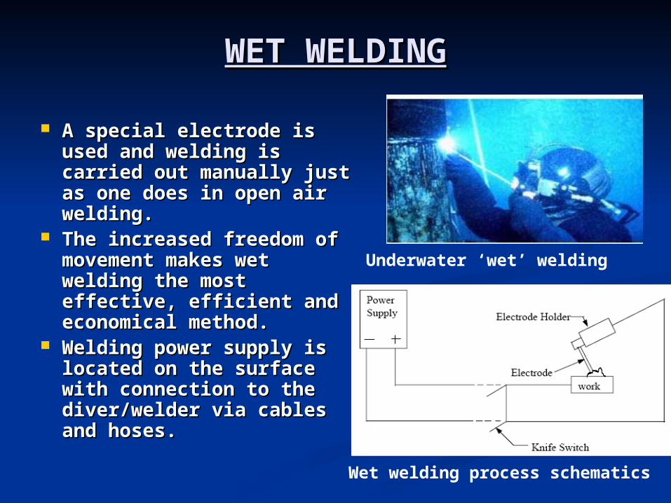
A special electrode is A special electrode is used and welding is used and welding is carried out manually just carried out manually just as one does in open air as one does in open air welding. welding.
The increased freedom of The increased freedom of movement makes wet movement makes wet welding the most welding the most effective, efficient and effective, efficient and economical method. economical method.
Welding power supply is Welding power supply is located on the surface located on the surface with connection to the with connection to the diver/welder via cables diver/welder via cables and hoses. and hoses.
Underwater ‘wet’ welding
Wet welding process schematics
The power source should be a direct current The power source should be a direct current machine rated at 300 or 400 Amperes machine rated at 300 or 400 Amperes
The welding machine frame must be grounded The welding machine frame must be grounded to the ship to the ship
The welding circuit must include a positive type The welding circuit must include a positive type of switch, usually a knife switch operated on the of switch, usually a knife switch operated on the surface and commanded by the welder-diver. surface and commanded by the welder-diver.
The knife switch in the electrode circuit must be The knife switch in the electrode circuit must be capable of breaking the full welding current and capable of breaking the full welding current and is used for safety reasonsis used for safety reasons
Special welding electrode holders with extra Special welding electrode holders with extra insulation against the water are used. The insulation against the water are used. The underwater welding electrode holder utilizes a underwater welding electrode holder utilizes a twist type head for gripping the electrode.twist type head for gripping the electrode.
The electrode types used conform to AWS E6013 The electrode types used conform to AWS E6013 classificationclassification
The electrodes must be waterproofed. All The electrodes must be waterproofed. All connections must be thoroughly insulated so connections must be thoroughly insulated so that the water cannot come in contact with the that the water cannot come in contact with the metal parts. metal parts.
Advantages of Wet WeldingAdvantages of Wet Welding The versatility and low cost of wet welding The versatility and low cost of wet welding
makes this method highly desirable. makes this method highly desirable. Other benefits include the speed. With Other benefits include the speed. With
which the operation is carried out. which the operation is carried out. It is less costly compared to dry welding. It is less costly compared to dry welding. The welder can reach portions of offshore The welder can reach portions of offshore
structures that could not be welded using structures that could not be welded using other methods. other methods.
No enclosures are needed and no time is No enclosures are needed and no time is lost in designing these enclosures (lost in designing these enclosures (as in as in dry weldingdry welding). Readily available standard ). Readily available standard welding machine and equipment are used. welding machine and equipment are used. The equipment needed for mobilization of The equipment needed for mobilization of a wet welded job is minimal. a wet welded job is minimal.
DISADVANTAGES OF WET DISADVANTAGES OF WET
WELDINGWELDING There is rapid quenching of the weld metal by There is rapid quenching of the weld metal by
the surrounding water. Although quenching the surrounding water. Although quenching increases the tensile strength of the weld, it increases the tensile strength of the weld, it decreases the ductility and impact strength of decreases the ductility and impact strength of the weldment and increases porosity and the weldment and increases porosity and hardness. hardness.
Hydrogen EmbrittlementHydrogen Embrittlement – Large amount of – Large amount of hydrogen is present in the weld region, hydrogen is present in the weld region, resulting from the dissociation of the water resulting from the dissociation of the water vapour in the arc region. The H2 dissolves in vapour in the arc region. The H2 dissolves in the Heat Affected Zone (HAZ) and the weld the Heat Affected Zone (HAZ) and the weld metal, which causes embrittlement, cracks and metal, which causes embrittlement, cracks and microscopic fissures. Cracks can grow and may microscopic fissures. Cracks can grow and may result in catastrophic failure of the structure. result in catastrophic failure of the structure.
Another disadvantage is poor visibility. The Another disadvantage is poor visibility. The welder some times is not able to weld properlywelder some times is not able to weld properly

HYPERBARIC WELDING (DRY HYPERBARIC WELDING (DRY WELDING) WELDING)
Hyperbaric welding is carried out in chamber sealed Hyperbaric welding is carried out in chamber sealed around the structure to be welded. around the structure to be welded.
The chamber is filled with a gas (generally helium The chamber is filled with a gas (generally helium containing 0.5 bar of oxygen) at the prevailing containing 0.5 bar of oxygen) at the prevailing pressure.pressure.
The habitat is sealed onto the pipeline and filled with The habitat is sealed onto the pipeline and filled with a breathable mixture of helium and oxygen, at or a breathable mixture of helium and oxygen, at or slightly above the ambient pressure at which the slightly above the ambient pressure at which the welding is to take place.welding is to take place.
This method produces high-quality weld joints that This method produces high-quality weld joints that meet X-ray and code requirements.meet X-ray and code requirements.
The TIG welding process is employed for this process.The TIG welding process is employed for this process. The area under the floor of the Habitat is open to The area under the floor of the Habitat is open to
water. water. Thus the welding is done in the dry but at the Thus the welding is done in the dry but at the
hydrostatic pressure of the sea water surrounding the hydrostatic pressure of the sea water surrounding the Habitat. Habitat.
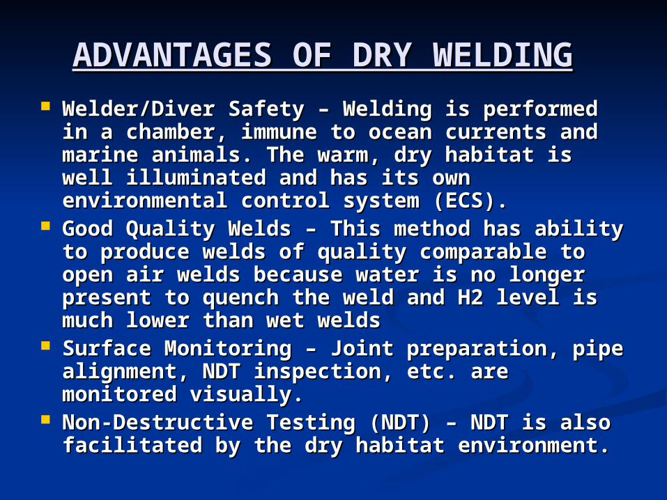
ADVANTAGES OF DRY ADVANTAGES OF DRY WELDINGWELDING
Welder/Diver Safety – Welding is performed in Welder/Diver Safety – Welding is performed in a chamber, immune to ocean currents and a chamber, immune to ocean currents and marine animals. The warm, dry habitat is well marine animals. The warm, dry habitat is well illuminated and has its own environmental illuminated and has its own environmental control system (ECS). control system (ECS).
Good Quality Welds – This method has ability Good Quality Welds – This method has ability to produce welds of quality comparable to to produce welds of quality comparable to open air welds because water is no longer open air welds because water is no longer present to quench the weld and H2 level is present to quench the weld and H2 level is much lower than wet weldsmuch lower than wet welds
Surface Monitoring – Joint preparation, pipe Surface Monitoring – Joint preparation, pipe alignment, NDT inspection, etc. are alignment, NDT inspection, etc. are monitored visually. monitored visually.
Non-Destructive Testing (NDT) – NDT is also Non-Destructive Testing (NDT) – NDT is also facilitated by the dry habitat environment. facilitated by the dry habitat environment.
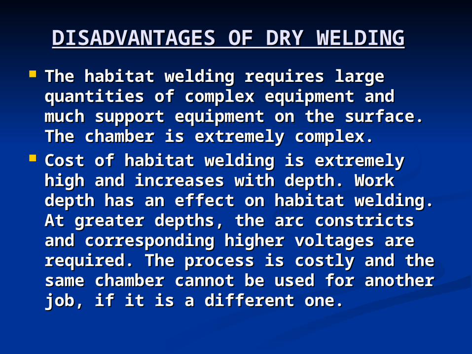
DISADVANTAGES OF DRY DISADVANTAGES OF DRY
WELDINGWELDING The habitat welding requires large The habitat welding requires large
quantities of complex equipment and quantities of complex equipment and much support equipment on the surface. much support equipment on the surface. The chamber is extremely complex.The chamber is extremely complex.
Cost of habitat welding is extremely high Cost of habitat welding is extremely high and increases with depth. Work depth and increases with depth. Work depth has an effect on habitat welding. At has an effect on habitat welding. At greater depths, the arc constricts and greater depths, the arc constricts and corresponding higher voltages are corresponding higher voltages are required. The process is costly and the required. The process is costly and the same chamber cannot be used for same chamber cannot be used for another job, if it is a different one. another job, if it is a different one.

RETURN TO MAIN CONTENTSRETURN TO MAIN CONTENTS
EXIT SLIDE SHOWEXIT SLIDE SHOW
SCOPE OF PRESENTATIONSCOPE OF PRESENTATION
Welding Quality assurance is Welding Quality assurance is divided into the followingdivided into the following: -: -
WPS – Welding Procedure SpecificationWPS – Welding Procedure Specification
PQR -Performance Qualification RecordPQR -Performance Qualification Record
WPQ –Welder Performance QualificationWPQ –Welder Performance Qualification
QUALITIES OF A GOOD WELDQUALITIES OF A GOOD WELD
The good qualities that are looked for in a weld comprise of the following: (a)Physical soundness (freedom from discontinuities) (b)Metallurgical compatibility
These are the qualities ,based on which the welder is judged
Physical soundnessPhysical soundness is related to the mode is related to the mode of deposition, in other words, the process of deposition, in other words, the process techniques as influenced by the skill of techniques as influenced by the skill of the welder or welding machine operator. the welder or welding machine operator.
Metallurgical compatibilityMetallurgical compatibility depends on the depends on the chemical composition of the chemical composition of the base-metal/filler-metal/flux or gas, the heat base-metal/filler-metal/flux or gas, the heat cycles that the weldment is going to cycles that the weldment is going to undergo while welding and post-weld heat undergo while welding and post-weld heat treatment.treatment.
The ultimate aim of all Quality assurance The ultimate aim of all Quality assurance schemes, i.e. Welder qualification, schemes, i.e. Welder qualification, Welding procedure specifications and Welding procedure specifications and Procedure qualification records, is to Procedure qualification records, is to ensure the soundness of welding. ensure the soundness of welding.
No matter what equipment is used to No matter what equipment is used to achieve these standards, the skill of the achieve these standards, the skill of the operator is of primary importance, hence operator is of primary importance, hence the requirement of “the requirement of “Welder Performance Welder Performance QualificationQualification” tests” tests..
WELDING PROCEDURE SPECIFICATION
From a designer’s point-of-view, the properties of the weld joint are designated as follows:
(a) Weld metal chemistry(b) Ultimate tensile strength(c) Yield point(d) Percentage elongation(e) Hardness(f) Impact strength, etc.
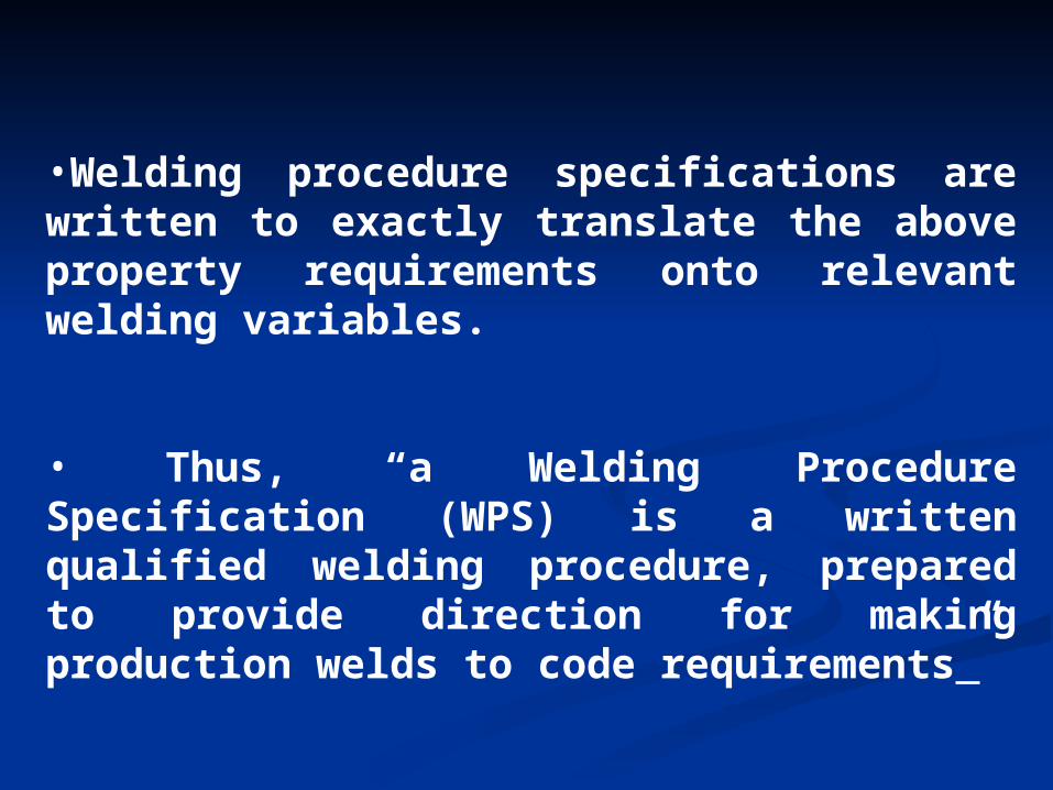
•Welding procedure specifications are written to exactly translate the above property requirements onto relevant welding variables.
• Thus, “a Welding Procedure Specification (WPS) is a written qualified welding procedure, prepared to provide direction for making production welds to code requirements”
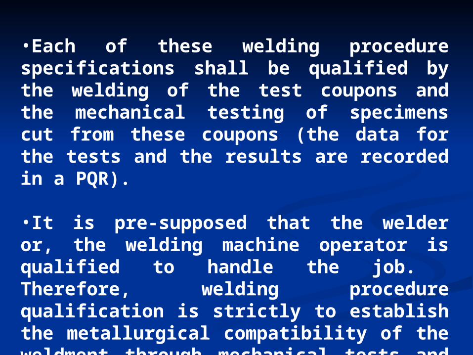
•Each of these welding procedure specifications shall be qualified by the welding of the test coupons and the mechanical testing of specimens cut from these coupons (the data for the tests and the results are recorded in a PQR).
•It is pre-supposed that the welder or, the welding machine operator is qualified to handle the job. Therefore, welding procedure qualification is strictly to establish the metallurgical compatibility of the weldment through mechanical tests and not the skill of the welder of the welding operator.
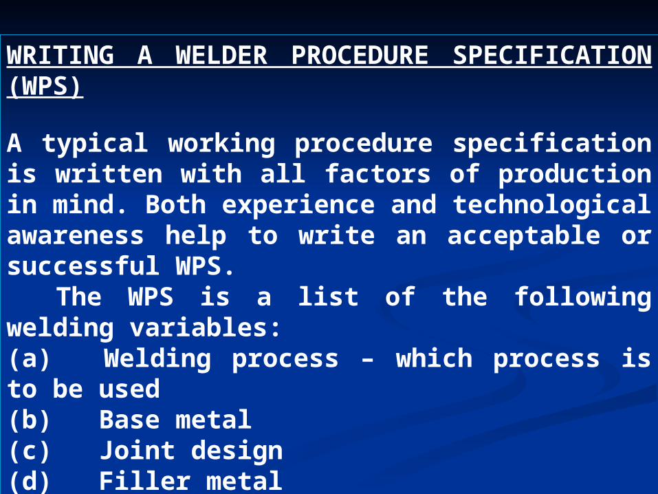
WRITING A WELDER PROCEDURE SPECIFICATION (WPS)
A typical working procedure specification is written with all factors of production in mind. Both experience and technological awareness help to write an acceptable or successful WPS. The WPS is a list of the following welding variables:(a) Welding process – which process is to be used(b) Base metal(c) Joint design(d) Filler metal(e) Welding position
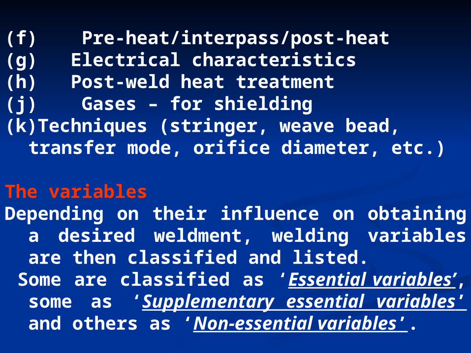
(f) Pre-heat/interpass/post-heat(g) Electrical characteristics(h) Post-weld heat treatment(j) Gases – for shielding(k)Techniques (stringer, weave bead, transfer mode,
orifice diameter, etc.)
The variablesDepending on their influence on obtaining a desired
weldment, welding variables are then classified and listed.
Some are classified as ‘Essential variables’, some as ‘Supplementary essential variables’ and others as ‘Non-essential variables’.
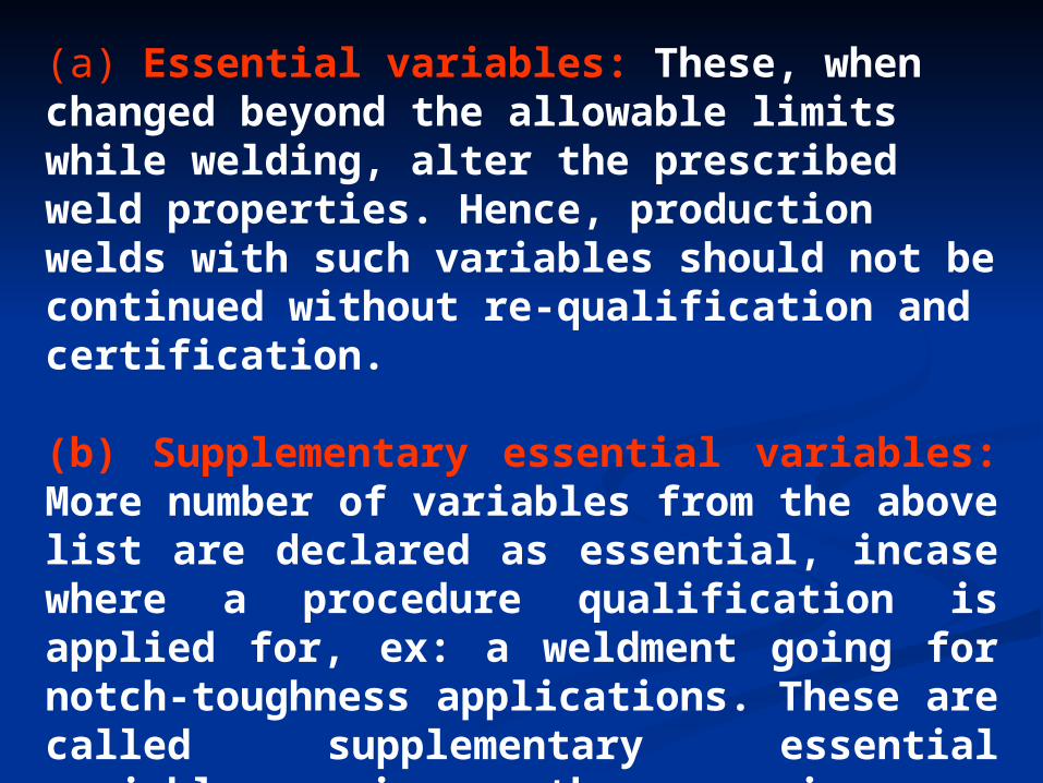
(a) Essential variables: These, when changed beyond the allowable limits while welding, alter the prescribed weld properties. Hence, production welds with such variables should not be continued without re-qualification and certification.
(b) Supplementary essential variables: More number of variables from the above list are declared as essential, incase where a procedure qualification is applied for, ex: a weldment going for notch-toughness applications. These are called supplementary essential variables, i.e. there arises a supplementary requirement that makes these variables essential.
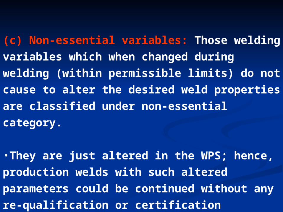
(c) Non-essential variables: Those welding variables
which when changed during welding (within
permissible limits) do not cause to alter the desired
weld properties are classified under non-essential
category.
•They are just altered in the WPS; hence, production
welds with such altered parameters could be
continued without any re-qualification or
certification
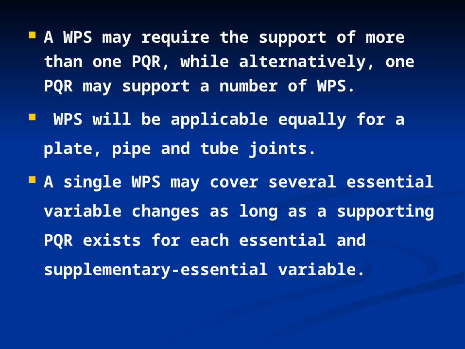
A WPS may require the support of more than
one PQR, while alternatively, one PQR may
support a number of WPS.
WPS will be applicable equally for a plate,
pipe and tube joints.
A single WPS may cover several essential
variable changes as long as a supporting
PQR exists for each essential and
supplementary-essential variable.
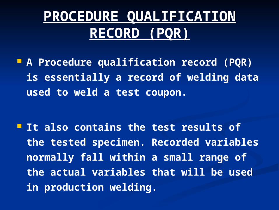
PROCEDURE QUALIFICATION RECORD (PQR)
A Procedure qualification record (PQR) is
essentially a record of welding data used to
weld a test coupon.
It also contains the test results of the tested
specimen. Recorded variables normally fall
within a small range of the actual variables
that will be used in production welding.

Changes to PQR are generally not permitted,
except in cases of editorial correction to the
entries or in the case of an agenda being
added. All changes in a PQR would call for re-
qualification
When more than one welding process or filler
metal is used to weld a test coupon, the
deposit weld-metal thickness of each process
and the filler metal would be recorded.
WELDER PERFORMANCE WELDER PERFORMANCE QUALIFICATIONS (WPQ)QUALIFICATIONS (WPQ)
The basic attempt is to establish the ability of The basic attempt is to establish the ability of
the welder to deposit sound quality of metal.the welder to deposit sound quality of metal.
In the case of welding operator qualification, In the case of welding operator qualification,
his ability to operate the welding machine is his ability to operate the welding machine is
tested and acknowledged.tested and acknowledged.
During qualification tests, only essential variables, as applicable to the welder’s skill, are considered.
Production welds with altered variables should not be continued without additionally qualifying the welder.
A welding machine operator usually gets qualified along with a procedure test.
The welder’s performance test has to be The welder’s performance test has to be limited only to verify his ability to deposit limited only to verify his ability to deposit sound metal and the requirements of sound metal and the requirements of metallurgical compatibility are to be metallurgical compatibility are to be attributed to the welding process attributed to the welding process characteristicscharacteristics
CODES FOR PERFORMANCE CODES FOR PERFORMANCE QUALIFICATIONS AND QUALIFICATIONS AND
ACCEPTANCE OF DEFECTSACCEPTANCE OF DEFECTS
A large number of industrial codes are A large number of industrial codes are
available which recognize pre-qualified available which recognize pre-qualified
welding procedures, as the manufacturing welding procedures, as the manufacturing
firms are to produce the documentary firms are to produce the documentary
evidence for such procedures as in vogue in evidence for such procedures as in vogue in
their organizations. their organizations.
The selection, training and qualification of The selection, training and qualification of
welders is the next stepwelders is the next step

Some popular codes used are as follows:
(a) Indian boiler regulations (IBR – chapter
viii)
(b) ASME Boiler and Pressure vessel code
(c) DIN 8560 (German standards - testing of
welders section)
(d) BS – 4872 (British standards)

Welders are to weld a test coupon, which Welders are to weld a test coupon, which
may be a pipe or a plate. may be a pipe or a plate.
The test coupons are then subjected to The test coupons are then subjected to
Radiography testing. Radiography testing.
The metallurgical compatibility of the weld is The metallurgical compatibility of the weld is
revealed only by running mechanical tests; revealed only by running mechanical tests;
hence face-bend tests and root bend tests hence face-bend tests and root bend tests
are also carried out in addition to are also carried out in addition to
Radiographic testingRadiographic testing
““Welders are out-rightly failed for the Welders are out-rightly failed for the
following defects” (All other defects ate following defects” (All other defects ate
acceptable within limits)acceptable within limits)
Severe root porosities/Blow holes.Severe root porosities/Blow holes.
Cluster of porosities.Cluster of porosities.
Cracks.Cracks.
Lack of fusion/Incomplete penetration.Lack of fusion/Incomplete penetration.
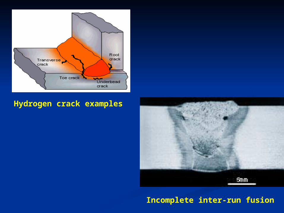
Hydrogen crack examples
Incomplete inter-run fusion
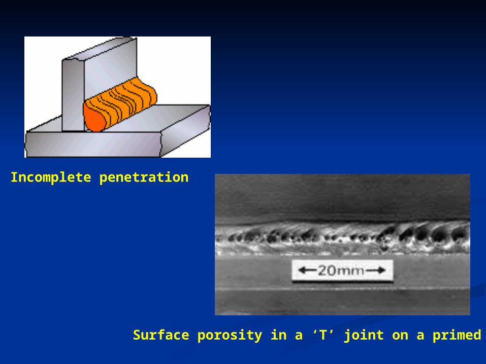
Surface porosity in a ‘T’ joint on a primed plate
Incomplete penetration
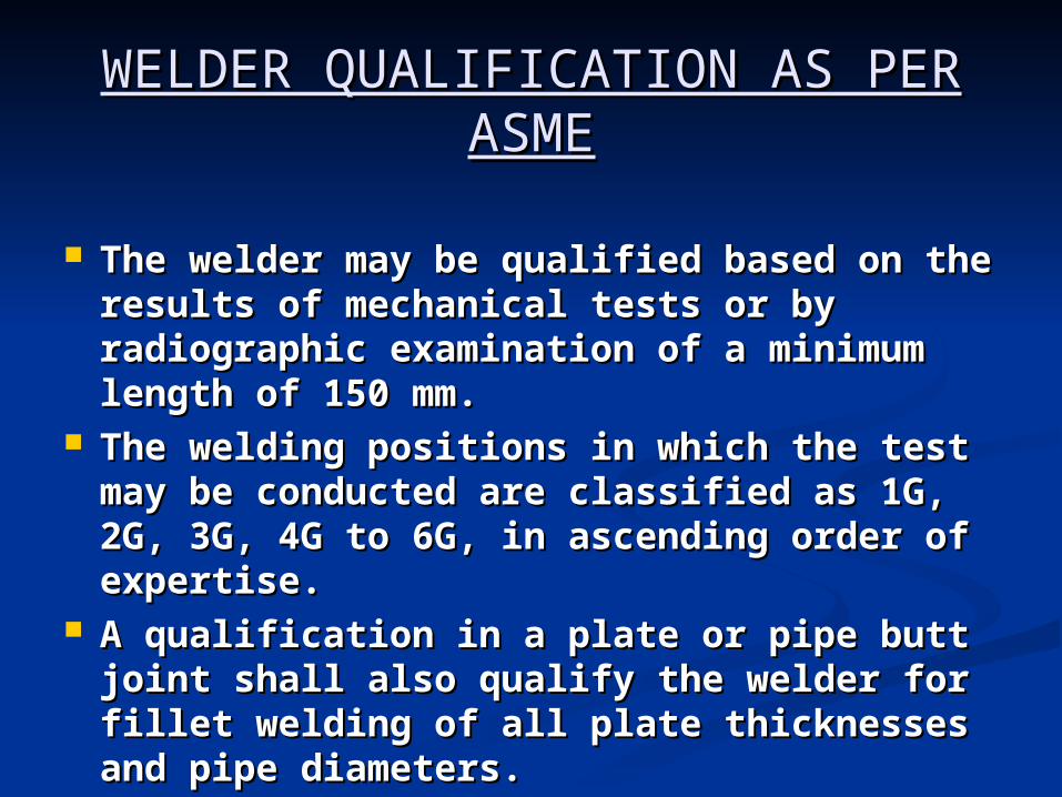
WELDER QUALIFICATION AS PER WELDER QUALIFICATION AS PER ASMEASME
The welder may be qualified based on the The welder may be qualified based on the results of mechanical tests or by results of mechanical tests or by radiographic examination of a minimum radiographic examination of a minimum length of 150 mm. length of 150 mm.
The welding positions in which the test may The welding positions in which the test may be conducted are classified as 1G, 2G, 3G, be conducted are classified as 1G, 2G, 3G, 4G to 6G, in ascending order of expertise. 4G to 6G, in ascending order of expertise.
A qualification in a plate or pipe butt joint A qualification in a plate or pipe butt joint shall also qualify the welder for fillet welding shall also qualify the welder for fillet welding of all plate thicknesses and pipe diameters.of all plate thicknesses and pipe diameters.

RETURN TO MAIN CONTENTSRETURN TO MAIN CONTENTS
EXIT SLIDE SHOWEXIT SLIDE SHOW