Embed Size (px)
Citation preview

Introduction to Transformer Rated Meters
Module 14187rd Annual Short Course and Conference
Southeastern Electricity Metering Association
November, 2012Orlando, FL
Larry WatersGeneral Electric Company
Atlanta, GA
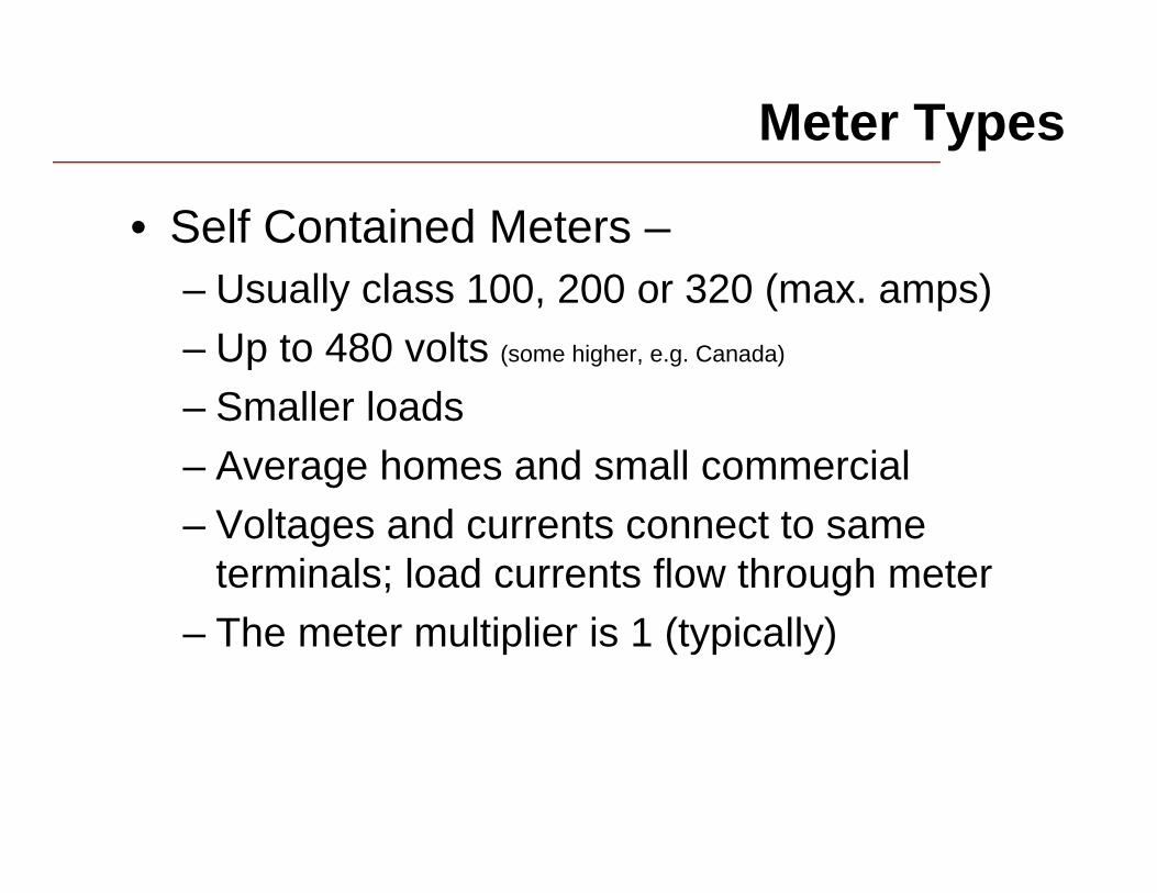
Meter Types
• Self Contained Meters –– Usually class 100, 200 or 320 (max. amps)– Up to 480 volts (some higher, e.g. Canada)
– Smaller loads– Average homes and small commercial– Voltages and currents connect to same
terminals; load currents flow through meter– The meter multiplier is 1 (typically)

Meter Types
• Self Contained Meters –– Voltages and currents connect to same
terminals; load currents flow through meter
– The meter multiplier is 1 (typically); may be 10 depending on how “dials” are displayed
Line
Load
N A C
2S

Meter Types
• Transformer Rated Meters --– Class 10 or 20; generally CL 20 today– Load currents above 200 amps and/or
voltages above 480v. (typically)
– Used with voltage transformers and/or current transformers
– Larger commercial and industrial customers; large homes
– Voltages and currents connect to separate terminals on meter
– The meter multiplier is not 1 (normally)

Meter Types
• Transformer Rated Meters --– Voltages and currents connect to separate
terminals on meter
– The meter multiplier is not 1 (normally); it is the product of the VT and CT ratios
A LINEC LINEN LINE
A LOADC LOADN LOAD
4S

Transformer Rated Meters - Safety
A LINE
C LINE
N LINE
A LOAD
C LOAD
N LOAD
4S
Voltage transformers should never be shorted.
Current transformers must always be shorted when not in use; never “pull” a transformer rated meter unless CT circuits are shorted.

Transformer Rated Meters
A LINE
C LINE
N LINE
A LOAD
C LOAD
N LOAD
4S
Voltage transformer –transforms the voltage; typically to 120 volts from the primary voltage
Current transformer –transforms the current; typically to 5 amps from the primary current
Polarity must be observed for CT’s and VT’s
The “ratio” is expressed as X to Y (X:Y) and represents the rated primary value as compared to the secondary value.
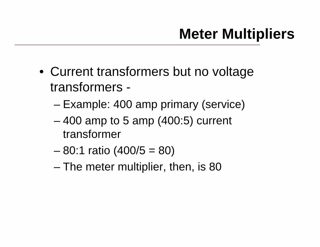
Meter Multipliers
• Current transformers but no voltage transformers -– Example: 400 amp primary (service)– 400 amp to 5 amp (400:5) current
transformer– 80:1 ratio (400/5 = 80)– The meter multiplier, then, is 80

Meter Multipliers
• Current transformers and voltage transformers -– Example: Service is 12470Y/7200 volts
and rated 400 amps– VT’s are connected phase to neutral –
7200:120 or 60:1– 400 amp to 5 amp (400:5) current
transformers – 80:1)– The meter multiplier, then, is 60 x 80 or
4800

Meter Multipliers
• “Dial” Multipliers and Primary Reading Registers– Meter register must show the actual
primary usage values– Example: Transformer Factor is 4800– Meter multiplies values by 4800 and
displays result– A dial multiplier may be required to prevent
“wrap around”, e.g. x100, x1000, etc.

Blondel’s Theorem
Blondel says:
If energy be supplied to any system of conductors through N wires, the total power in the system is given by the algebraic sum of readings of N wattmeters, so arranged that each of the N wires contains one current coil, the corresponding potential coil being connected between that wire and some common point. If this common point is on one of the N wires, the measurement may be made by the use of N-1 wattmeters.
Andre E. Blondel, 1893
• We would use “watthour meters” in place of “watt meters” and “energy” in place of “power”.
• We would also consider “ground” as a possible current carrying conductor when counting “N”.
What is a meter Form Number?• A Form designation tells us:
– The number and arrangement of meter terminals, and– The number and internal connection of meter elements
(stators).• The Form designation describes the meter, not the
service.– With modern meters, some meter Forms may be used to
correctly meter more than one service configuration.– More than one meter Form could be used with a
particular service depending on the connection of the Instrument Transformers.
• The same Form designation is usually applicable to equivalent meters of all manufacturers.

Basic Meter Forms
* Not intended for Form 5S equivalent, 4 wire delta connections. ** Some electronic meters may be used in 4wY or 4w circuits.
SC = Self Contained; TR = Transformer Rated S = Socket Base; A = Bottom Connected
MeterForm
S.C./T.R.
Number ofStators
Number ofCurrent Circuits
Number of ExternalCircuit Wires
1S, 1A SC 1 1 22S, 2A SC 1 2 33S, 3A TR 1 1 24S, 4A TR 1 2 35S, 5A TR 2 2 3 (or 4)35S, 35A TR 2 2 3*45S, 45A TR 2 2 3 (or 4)6S, 6A TR 2 3 4Y36S, 36A TR 2 3 4Y8S, 8A TR 2 3 49S, 9A TR 3 3 4Y (or **)12S, 12A SC 2 2 314S, 14A SC 2 3 4Y15S, 15A SC 2 3 416S, 16A SC 3 3 4Y (or **)

Self Contained vs Transformer Rated
What is one of the key differences . . . . . . when we look at ANSI forms?
Line
Load
N A C
2S
A LINE
C LINE
N LINE
A LOAD
C LOAD
N LOAD
4S
Self-Contained Transformer-Rated

Applicable ANSI Meter Forms
* ANSI Forms looking from the front of the meter
Form 4S*
“1-1/2” Element,
Transformer Rated
3 wire, single phase
Form 3S*
1 Element,
Transformer Rated
2 wire, single phase,
3 wire, single phase

Applicable ANSI Meter Forms
* ANSI Forms looking from the front of the meter
Form 5* Form 35* Form 45*
2 Element, 3 wire, network
2 Element, 3 wire, network
2 Element, 3 wire, network

Polyphase Meters
3S
A LINEN LINE
A LOADN LOAD
3S
B LINEN LINE
B LOADN LOAD
3S
C LINEN LINE
C LOADN LOAD
4 Wire Wye Services

4 wire Wye Metering
Form 9
3 Element,
4 wire, wye
K Y Z
Form 6
2½ Element,
4 wire, wye
Form 36
2½ Element,
4 wire, wye
Transformer-rated
K Y ZK Y Z

4 wire, Wye Metering
Transformer-rated
9S
C
A
B
N
K Y Z

4 Wire, Delta Metering
N
9S
K Y Z
A LOADB LOADC LOADN LOAD
C
B
A
Summary
• Transformer rated meters are required when voltages and currents exceed the meter’s direct connect capability
• A form designation tells us about the number or terminals, their location and the internal meter wiring
• In CT and VT connections, polarity must be observed for metering to be correct
• CT’s must be shorted when not in use; VT’s should not be shorted
• Meter multipliers are critical in transformer rated applications