Embed Size (px)
Citation preview
A
Seminar Report
On
““IInnttrroodduuccttiioonn ttoo TTiiAAllNN CCooaattiinngg””
Submitted by
HHaannwwaannttee SSaarraanngg RR
Exam No.: B 2101325
Seminar Guide:
Prof. B R Kharde
Department of Production Engineering, Amrutvahini College of Engineering,
Sangamner - 422608. 2002-2003

AAmmrruuttvvaahhiinnii CCoolllleeggee ooff EEnnggiinneeeerriinngg SSaannggaammnneerr
DDeeppaarrttmmeenntt ooff PPrroodduuccttiioonn EEnnggiinneeeerriinngg 22000022--22000033
CC EE RR TT II FF II CC AA TT EE
This is to certify that the Seminar Report entitled,
““IInnttrroodduuccttiioonn ttoo TTiiAAllNN CCooaattiinngg””
has been submitted by
HHaannwwaannttee SSaarraanngg RR
as a partial fulfillment for the Bachelor Degree in Production Engineering
Prof. B R Kharde Seminar Guide
Air Cmde. (Retd.) Dr. A P Valavade Prof. Dr. M A Venkatesh PRINCIPAL HOD

UUNNIIVVEERRSSIITTYY OOFF PPUUNNEE
AMRUTVAHINI COLLEGE OF ENGINEERING SANGAMNER DEPARTMENT OF PRODUCTION ENGINEERING
2002-2003
C E R T I F I C A T E
This is to certify that
Hanwante Sarang R Student of B.E. (Production Engineering) was examined in the Seminar entitled
““IInnttrroodduuccttiioonn ttoo TTiiAAllNN CCooaattiinngg””
on /12/2002 at
AAmmrruuttvvaahhiinnii CCoolllleeggee ooff EEnnggiinneeeerriinn gg
SSaannggaammnneerr..
INTERNAL EXAMINER EXTERNAL EXAMINER
Acknowledgement
Team spirit, commandment are basic ingredients of any group task, be it sports
area or the battlefield or a several occasions in our own life. Similarly, this is a result of
contributions from a student, the staff members Amrutvahini College of Engineering,
Sangamner.
I would like to thank our beloved Guide Prof. B R Kharde a person who has
earned out admiration and respect for helping me at the time of difficulties. I would like
to thank our beloved Principal Prof. Air Cmde. (Retd.) Dr. A P Valavade who has been
constant source of encouragement and inspiration and HOD Prof. Dr. M A Venkatesh
for his timely help.
I would also like to thank the person from industries like;
1. Mr. Mahesh Gole, Managing Director, Gole Precision Tools, Pune.
2. Mr. Anand Golikere, (Asst. Manager Marketing), Balzers (India) Limited, Pune.
3. Mr. Sujeet Pradhan, (Sr. Engineer Marketing), Balzers (India) Limited, Pune.
4. Mr. Milind R Salvi, (Superintendent Production), Balzers (India) Limited, Pune .
5. Mr. N Meenakshi Sundaram, Sales and Service Engineer, Widia (India) Limited,
Nashik.
who has been constant source of encouragement and inspiration and helping me at the
time of difficulties.
And last but not the least, my many thanks to the personal, who is related with this
seminar.
Hanwante Sarang R B.E. (Production)
Abstract
With the demands of lower cost, higher accuracy, better surface finish, and
shorter process time in the precision engineering industry, high-speed machining of high-
hardness materials including hardened tool steels has become increasingly important. To
improve the performance and to extend the life of the cutting tools, various types of hard
coatings have been developed. Hard coatings for high-speed machining consist of
multiple layers because of the requirements for high-adhesion strength to the substrate,
high-thermal stability, high hardness, a low-friction coefficient, and good compatibility.
The present techniques used to produce these coatings include physical-vapor deposition,
such as sputtering and ion plating, and plasma-enhanced chemical vapor deposition.
Traditionally used coatings like TiN, CrN, and their alloyed nitride coatings, have high
hardness and good adhesion strength on common materials used in the tooling industry.
However, these coatings have poor performance in high-speed machining applications,
especially in the cutting of hardened tool steels, because of phase transition (oxidation) at
high temperatures. One of the most promising systems for this application is Ti–Al
alloyed ceramic (nitride and/or carbide) i.e. Titanium Aluminum Nitride (TiAlN),
which has high-thermal stability, a low-friction coefficient, and high hardness. Much
work has been done worldwide to develop and commercialize this coating for high-speed
cutting and milling tools.
Contents
1. INTRODUCTION. … 1
1.1 Tool Wear … 1
2. TOOL COATINGS. … 3
2.1 Properties Of Cutting Tool Materials … 3
2.2 Necessity Of Coatings … 3
2.3 Types Of Coatings … 5
3. TiAlN PROPERTIES. … 7
3.1 Standard Coating Application Chart … 7
3.2 Grades & Advantages of PVD Coat Insert … 7
3.3 Comparison Chart … 8
3.4 Advantage of TiAlN Coating Over TiN … 8
4. SCOPE OF TIALN COATED TOOL. … 11
4.1 Machining Tools … 11
4.2 Tools For Punching, Forming And Pressing … 11
5. Advantages of TiAlN Coating on Tools. … 12
6. CASE STUDY. … 14
6.1 Introduction … 14
6.2 Experiments … 14
6.3 Results And Discussions … 17
6.4 Summary … 21
7. CONCLUSION. … 22
BIBLIOGRAPHY. … 23

Introduction to TiAlN Coating.
1
1. INTRODUCTION
1.1 Tool Wear
As a result of load factors exerted on the cutting edge during machining, a few
basic wear mechanisms dominate metal cutting:
1. abrasion wear
2. diffusion wear
3. oxidation wear
4. fatigue wear (static or dynamic)
5. adhesion wear
The tool material's ability to resist the loads determines how it will be affected by
the wear mechanisms of metal cutting. Abrasion wear is caused mainly, but not entirely,
by the hard particles of the work piece material. This is similar to a grinding operation
where the hard particles come between the surface of the work piece and tool. The
mechanical load on the insert leads to wear on the flat face of the cutting-edge flank.
To a large extent, the cutting edge's ability to resist abrasive wear is connected to
its hardness. A tool material densely packed with the hardest of particles will stand up
well to abrasive wear, but it may not be equipped to cope with other load factors during
machining.
Diffusion wear is more affected by the chemical load during the cutting process.
The chemical properties of the tool material and the affinity of the tool material to the
work piece determine the development of the diffusion-wear mechanism. Hardness of the
tool material doesn't affect the process very much. The metallurgical relationship between
the materials determines the extent of the wear mechanism. Some cutting tool materials
are inert against many work piece materials, while others have high affinities.
Tungsten carbide and steel have affinity toward each other that creates a diffusion-
wear mechanism. This wear forms a crater on the insert's chip face. Because this
mechanism is very temperature dependent, it's more pronounced at higher cutting speeds.
Atomic interchange occurs with a two-way transfer of ferrite from the steel into the tool,
as well as carbon diffusing into the chip.
In the presence of air, high temperatures produce oxidation wear in most metals.
Tungsten and cobalt form porous oxide films that the chip rubs off more easily. But when

Introduction to TiAlN Coating.
2
stronger and harder oxides are produced (such as aluminum oxide), certain cutting-tool
materials may be more susceptible to oxidation wear. This is especially true with regard
to the interface portion of the cutting edge where the chip width finishes (at the depth of
cut). At this point, air gains access to the cutting process and oxidation can create notches
in the edge. This form of wear, however, is relatively uncommon in today's machining.
Fatigue wear is often a thermo-mechanical phenomenon. Fluctuations in
temperature and loading forces can crack or break cutting edges. Intermittent cutting
action leads to temperature cycling that creates shocks at the point where the cutting edge
engages the work piece. Some tool materials are more sensitive than others to the fatigue
mechanism. Pure mechanical failure can result from cutting forces that exceed the cutting
edge's mechanical strength. This can be caused by hard or strong work piece materials,
high feed rates, or when the tool material isn't hard enough. Usually, however, plastic
deformation is the principal form of fatigue wear.
Adhesion wear (also known as attrition wear) occurs mainly at low machining
temperatures on the tool's chip face. This can affect long-chipping and short-chipping
work piece materials including steel, aluminum and cast iron. This mechanism often
forms a built-up edge (BUE) between the chip and the cutting edge. In this process,
successive layers from the chip are welded and hardened, becoming part of the edge.
As machining continues, the BUE may shear off by itself or cause the tool's
cutting edge to break away (either in small pieces or by fracturing). Some cutting tool
materials and work pieces (for example, very ductile steel) are more susceptible to this
pressure-welding than others. At higher cutting temperatures, however, the conditions
that produce this phenomenon usually do not exist. An adhesion-wear mechanism
represents a combination of a specific temperature range, affinity between the tool and
work piece materials, as well as the load from cutting forces. When machining
deformation-hardening materials (for example, austenitic stainless steel) this wear
mechanism produces rapid local wear at the maximum limit of cutting depth. This is the
most common type of notch wear, and it depends on the affinity between the tool and
work piece materials.
This tool wear can be minimized by means of suitable coating on tools which
makes tool within the cutting forces and to sustain its properties and giving out no effect
on productivity. There are number of tool coatings available in market like TiN, TiC, and
TiAlN etc.

Introduction to TiAlN Coating.
3
2. TOOL COATINGS
2.1 Properties of Cutting Tool Materials:
Following are some important properties, which should be kept in mind while
selecting the coating material. Due to lack of these properties coating is made on the
substrate tool material.
1. High Wear Resistance: It is necessary to enable the cutting tool
to retain its shape and cutting efficiency.
2. Hot Hardness: It is necessary to enable the cutting tool to retain its cutting ability
and hardness at elevated temperatures.
3. Sufficient Toughness: It is necessary for the cutting tool to withstand the forces,
to absorb shocks associated with interrupted cuts and to prevent the chipping of
the fine cutting edge.
4. Adequate Strength: To withstand cutting forces.
5. Dimensional Stability: Tool material should be able to retain dimensions during
cutting operations.
2.2 Necessity of Coatings:
Though many developments in the cutting tool materials and surface treatments
are carried out, not a single material have a fruitful combination of all those properties
required by a machining process. In order to have longer tool lives and increase in
productivity, one must go for surface engineering on tools.
The harder materials lack in toughness and also they are sensitive to vibration and chatter.
The refractory materials possess excellent wear resistant material on a tougher substrate.
The coatings are extremely fined grained and dense with a high degree of purity.
As the coatings are diffused into the underlying metal, the bond is perfect. The coating
becomes a part of the tool. Low thermal conductivity properties also eliminate cold
welding and chip building-up. Thus a coating possesses excellent combination of above
mentioned properties.
The performance of coated and uncoated tools can be predicted with the help of
Fig.1 which is a graph of tool wear Vs time plotted under same machining conditions.

Introduction to TiAlN Coating.
4
Fig 1: Tool wear Vs time for coated and uncoated cemented carbide tool tips. Uncoated
steel cutting grade, coated WC-Co alloy, coated steel cutting grade.
Introduction to TiAlN Coating.
5
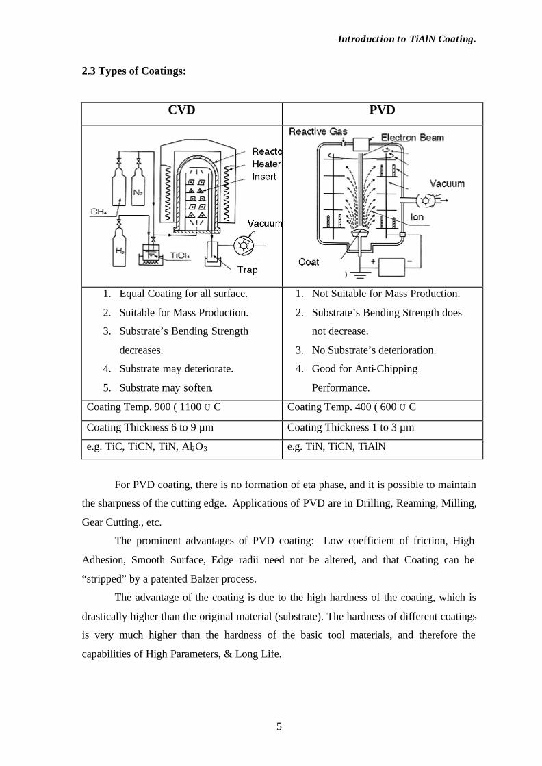
2.3 Types of Coatings:
CVD PVD
1. Equal Coating for all surface.
2. Suitable for Mass Production.
3. Substrate’s Bending Strength
decreases.
4. Substrate may deteriorate.
5. Substrate may soften.
1. Not Suitable for Mass Production.
2. Substrate’s Bending Strength does
not decrease.
3. No Substrate’s deterioration.
4. Good for Anti-Chipping
Performance.
Coating Temp. 900 ( 1100 U C Coating Temp. 400 ( 600 U C
Coating Thickness 6 to 9 µm Coating Thickness 1 to 3 µm
e.g. TiC, TiCN, TiN, Al2O3 e.g. TiN, TiCN, TiAlN
For PVD coating, there is no formation of eta phase, and it is possible to maintain
the sharpness of the cutting edge. Applications of PVD are in Drilling, Reaming, Milling,
Gear Cutting., etc.
The prominent advantages of PVD coating: Low coefficient of friction, High
Adhesion, Smooth Surface, Edge radii need not be altered, and that Coating can be
“stripped” by a patented Balzer process.
The advantage of the coating is due to the high hardness of the coating, which is
drastically higher than the original material (substrate). The hardness of different coatings
is very much higher than the hardness of the basic tool materials, and therefore the
capabilities of High Parameters, & Long Life.

Introduction to TiAlN Coating.
6
Basic Tool Materials (Hardness in VPN) Coatings (Hardness in VPN)
HSS: 720 VPN TiN: 2250 VPN
Hard Metal: 1400 VPN TiCN: 3000 VPN
FUTURA(TiAlN): 3500 VPN
Other advantages of hard coating on tools are: Chip flows smoothly; No Built-up
Edge; Very useful on Low alloy Steels, Tool Steels, and Stainless Steel.
The heat generated at the cutting edge – how it affects: In HSS tools, the heat
distribution is quick and high. In 5 seconds, the temperature rises to 90o C, and in 10
seconds it reaches the level of 120 o C. With Coating, the temperature does not rise
above 47o C)
It was clear that the chip formation with coated tools is cleaner, and chances of
welding or Built-Up Edge are removed. Due to the edge retention, these advantages of
chip formation are available over a long period.
Introduction to TiAlN Coating.
7
3. TiAlN PROPERTIES
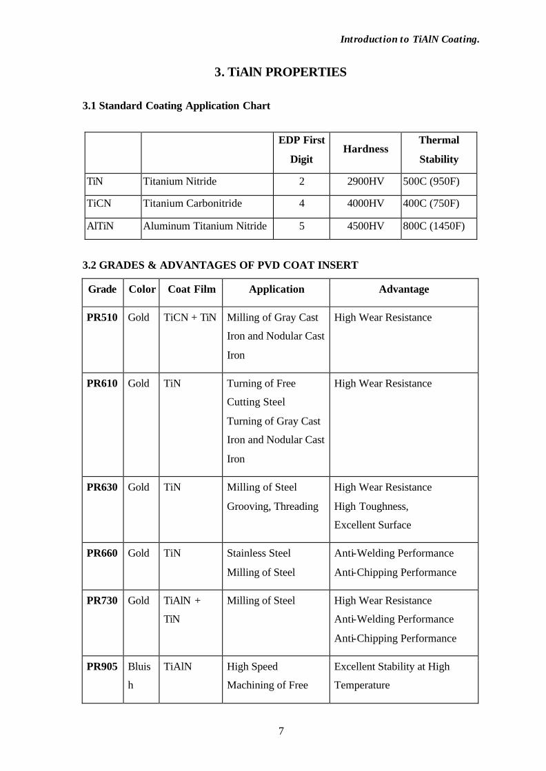
3.1 Standard Coating Application Chart
EDP First
Digit Hardness
Thermal
Stability
TiN Titanium Nitride 2 2900HV 500C (950F)
TiCN Titanium Carbonitride 4 4000HV 400C (750F)
AlTiN Aluminum Titanium Nitride 5 4500HV 800C (1450F)
3.2 GRADES & ADVANTAGES OF PVD COAT INSERT
Grade Color Coat Film Application Advantage
PR510 Gold TiCN + TiN Milling of Gray Cast
Iron and Nodular Cast
Iron
High Wear Resistance
PR610 Gold TiN Turning of Free
Cutting Steel
Turning of Gray Cast
Iron and Nodular Cast
Iron
High Wear Resistance
PR630 Gold TiN Milling of Steel
Grooving, Threading
High Wear Resistance
High Toughness,
Excellent Surface
PR660 Gold TiN Stainless Steel
Milling of Steel
Anti-Welding Performance
Anti-Chipping Performance
PR730 Gold TiAlN +
TiN
Milling of Steel High Wear Resistance
Anti-Welding Performance
Anti-Chipping Performance
PR905 Bluis
h
TiAlN High Speed
Machining of Free
Excellent Stability at High
Temperature
Introduction to TiAlN Coating.
8
Purpl
e
Cutting Stainless
Steel
Smooth Tool Surface
High Wear Resistance and
Plastic Deformation Resistance
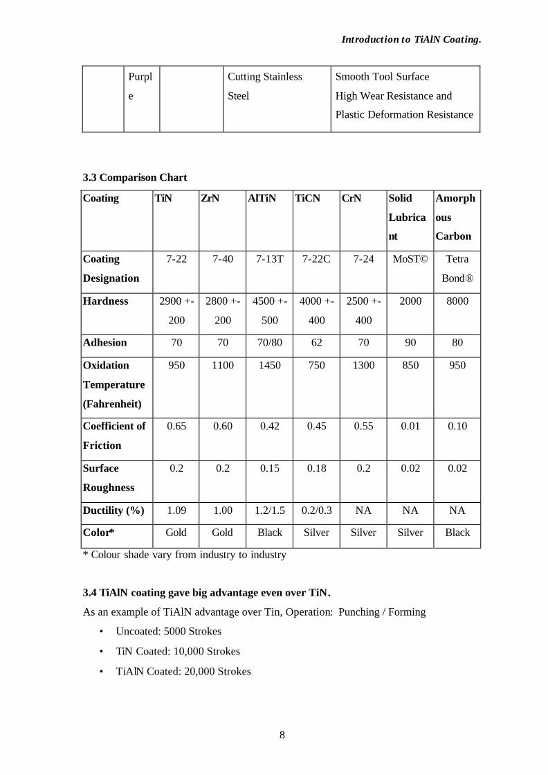
3.3 Comparison Chart
Coating TiN ZrN AlTiN TiCN CrN Solid
Lubrica
nt
Amorph
ous
Carbon
Coating
Designation
7-22 7-40 7-13T 7-22C 7-24 MoST© Tetra
Bond®
Hardness 2900 +-
200
2800 +-
200
4500 +-
500
4000 +-
400
2500 +-
400
2000 8000
Adhesion 70 70 70/80 62 70 90 80
Oxidation
Temperature
(Fahrenheit)
950 1100 1450 750 1300 850 950
Coefficient of
Friction
0.65 0.60 0.42 0.45 0.55 0.01 0.10
Surface
Roughness
0.2 0.2 0.15 0.18 0.2 0.02 0.02
Ductility (%) 1.09 1.00 1.2/1.5 0.2/0.3 NA NA NA
Color* Gold Gold Black Silver Silver Silver Black
* Colour shade vary from industry to industry
3.4 TiAlN coating gave big advantage even over TiN.
As an example of TiAlN advantage over Tin, Operation: Punching / Forming
• Uncoated: 5000 Strokes
• TiN Coated: 10,000 Strokes
• TiAlN Coated: 20,000 Strokes

Introduction to TiAlN Coating.
9
Constant research was going to see how best the heat can be carried away by the
chip. Thus came the development of BALINIT FUTURA – Titanium Aluminium
Nitride. This is very useful in Dry Machining; and has excellent resistance to Oxidation.
Almost concurrently, the development of BALINIT X TREME - Multi Layer
Coatings came through.
In FORMULA 1 racing cars, the gears are coated with BALINIT HARDLUBE
(TiAlN), Balinit FUTURA and Balinit XTREME are both product of TiAlN Coating.
For PVD Coating, there are two processes: IONITRON TECHNIQUE and ARC
TECHNIQUE. The IONITRON technique uses Electron Beam melting of Titanium under
High vacuum to give Very Smooth, Shiny, Adherent film without droplets. Titanium and
Nitrogen are bombarded onto the tool. This process is Microprocessor Controlled, and
Individual Control of Coating Parameters makes it possible to mix tools in one batch.
The following schematic figure gives us an idea about the process.
The major advantages are Extended Tool Life Time, Reduction of Machine
Downtime, Reduction of Maintenance Costs, consistently Good Quality of Parts Coming
Out, Suppression of Lubrication, Less Rejected Pieces and Smooth, Dent free, Wrinkle
free Pressed Parts. He cited the example of a French car manufacturer who was using
21,000 Tons of Lubricant for dies every year. With the use of Coated Dies and Punches,
this consumption reduced to 82 Tons / Year.
Introduction to TiAlN Coating.
10
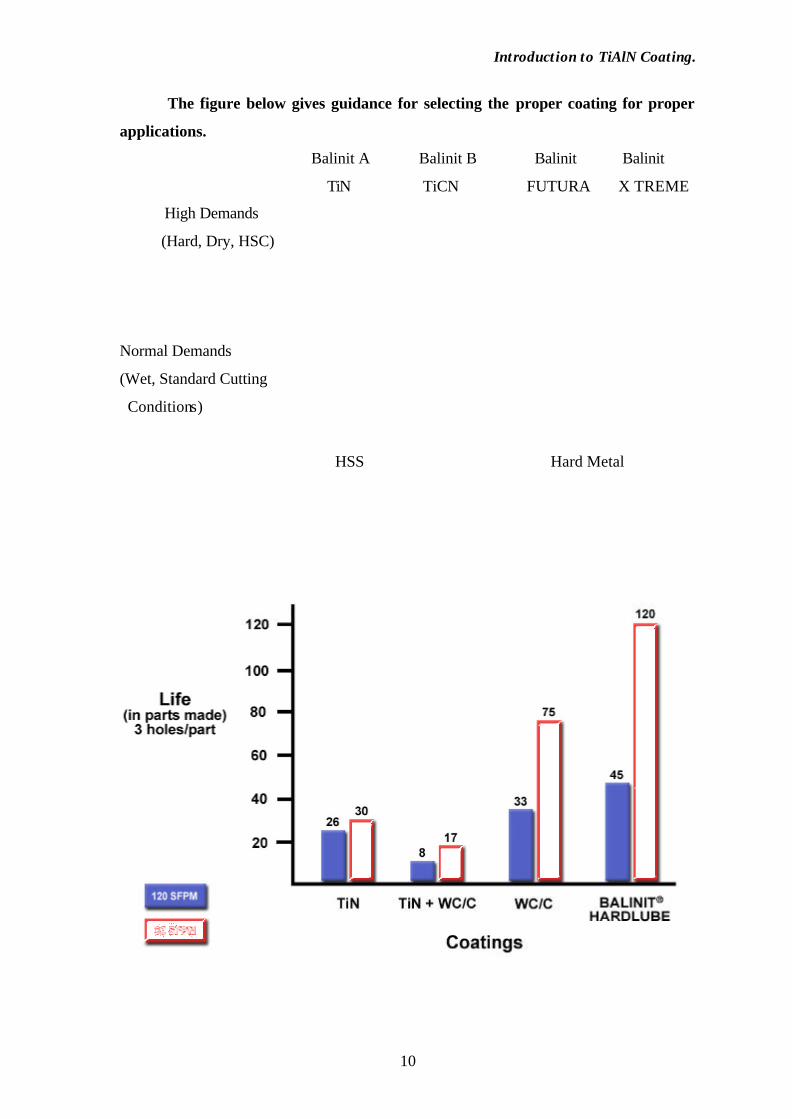
The figure below gives guidance for selecting the proper coating for proper
applications.
Balinit A Balinit B Balinit Balinit
TiN TiCN FUTURA X TREME
High Demands
(Hard, Dry, HSC)
Normal Demands
(Wet, Standard Cutting
Conditions)
HSS Hard Metal

Introduction to TiAlN Coating.
11
4. SCOPE OF TiAlN COATED TOOL.
4.1 Machining tools
Worked material Excellent Fine Satisfactory
High-alloyed steel, low alloy steel and stainless
steel at medium and high cutting speeds TiAlN TiCN TiN
High-alloyed steel, low alloy steel and stainless
steel at low cutting speeds, e.g. HSS milling
cutters
TiCN TiAlN TiN
Cast iron TiAlN TiCN TiN
Al and AlSi alloys, cast aluminum TiAlN TiCN CrN
Cu and Cu alloys, brass, bronze, aluminum
bronze, nickel silver, Ti and Ti alloys CrN TiAlN TiCN
Ni and Ni alloys, hard alloys, Hastelloy, Inconel TiAlN TiCN
Plastics TiAlN CrN TiCN
Graphite, green compact, plastics with filler (diamond) TiAlN
4.2 Tools for punching, forming and pressing
Worked material Excellent Fine Satisfactory
High and low alloy steel plate and sheet,
stainless steel plate and sheet TiCN TiAlN TiN
Al and Al alloys CrN TiAlN TiCN
Ti and Ti alloys, Cu and Cu alloys CrN TiAlN TiCN
Ni alloys, precious metals, gold, platinum TiAlN TiCN
Plastics, plastics with filler, glass, sintering
powder TiAlN CrN TiCN

Introduction to TiAlN Coating.
12
5. ADVANTAGES OF TiAlN COATING ON TOOLS
• Longer Tool Life
• Faster Machining Rates
• Fewer Re-sharpening.
• Fewer Setups
• Higher Productivity
• Better Part Finish
• Dry Machining
• Fast Payback on Initial Coating Investment
According to Balzers India Limited there are many advantageous features of TiAlN
Coating as;
1. Improve yields and productivity: Coated tool lasts for longer period time.
Moreover coated tools enables use of higher parameters.
2. Reduce machine Downtime: Coating acts as a wear indicator; tools change
frequency can now be calculated and planned. Resulting in minimized tool
breakage caused by fatigue and overuse.
3. Cut Manufacturing Stages: Coated tools allow higher degrees of metal
deformation enabling reduction of manufacturing stages. Also cleaning efforts is
considerably reduced as components with finer surface and with minimal coolant
are produced.
4. Reduced Costly and time consuming finishing operation: Coated tools stay in
shape longer and produce top-notch ready to install components with finer
surfaces, tighter manufacturing tolerances and better dimensional accuracy. This
is important particularly for work-pieces that need to look perfect.
5. Conserve consumables: The option for environmentally friendlier production
range from smaller lubricant quantities to dry production, as coated tools reduce
friction, generates less heat and moreover as coatings sustain high temperature
encountered during process. Cleaning can even be eliminated entirely in dry
processes – a must in food and pharmaceutical applications.
6. Be Eco-Friendly: With coated tools you use less and work with ecologically safer
lubricants. This not only reduces the effort and cost involved in re-conditioning
but also makes your Eco-balance look good.
Introduction to TiAlN Coating.
13
7. Cost across the board: Less is more – particularly in context of tool wear. TiAlN
Coatings makes a tangible contribution to cost savings in several respects
resulting in greater cost effectiveness.
8. Cut tooling costs: As coated tools results in less wear and lasts longer, enable
more re-grinds.
9. Cuts manufacturing costs: With improved productivity, reduced machine
downtime and higher cycle frequencies. Fewer tool failures also reduces load on
tool maintenance.
10. Cut Cost of quality: With reduced inspection cost due to reliability process
control coated tools invariably produce top-notch ready to install components with
finer surfaces, tighter manufacturing tolerances and better dimensional accuracy.
Also coated tool reduce rejection and generates less scrap.
11. Cut expenses on consumables: Coated tools ensure reliable separation of tool
and work-piece even under adverse lubrication condition avoiding seizure
resulting in significantly reduces cost of coolant \ lubricants.
Introduction to TiAlN Coating.
14
6. CASE STUDY
6.1. INTRODUCTION
This Case Study reports the development of a multilayered (Ti, Al, N) Ceramic
hard coating for high-speed machining tools using an unbalanced magnetron-sputtering
system. The process parameter dependence of the coating properties was studied and
discussed. High-speed-milling field testing on hardened tool steel was also investigated.
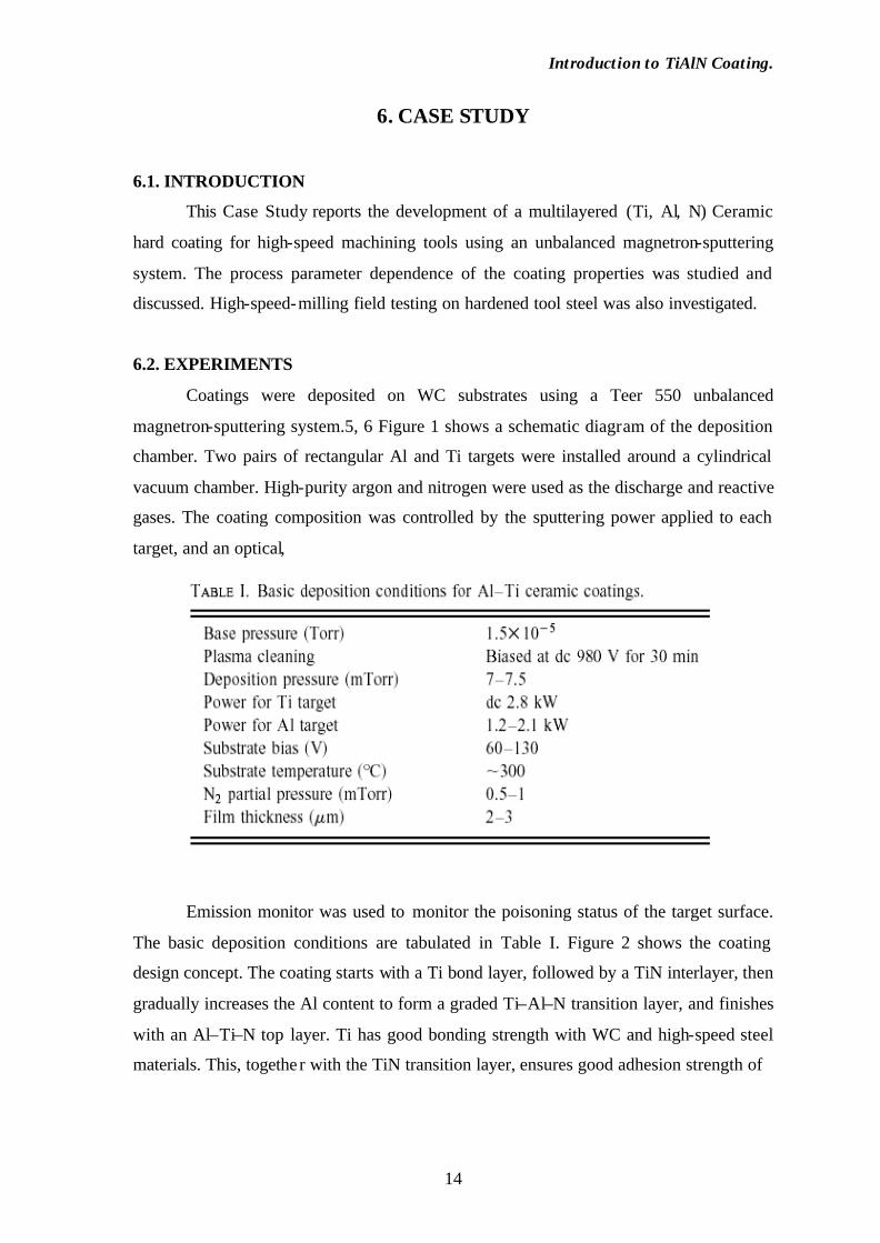
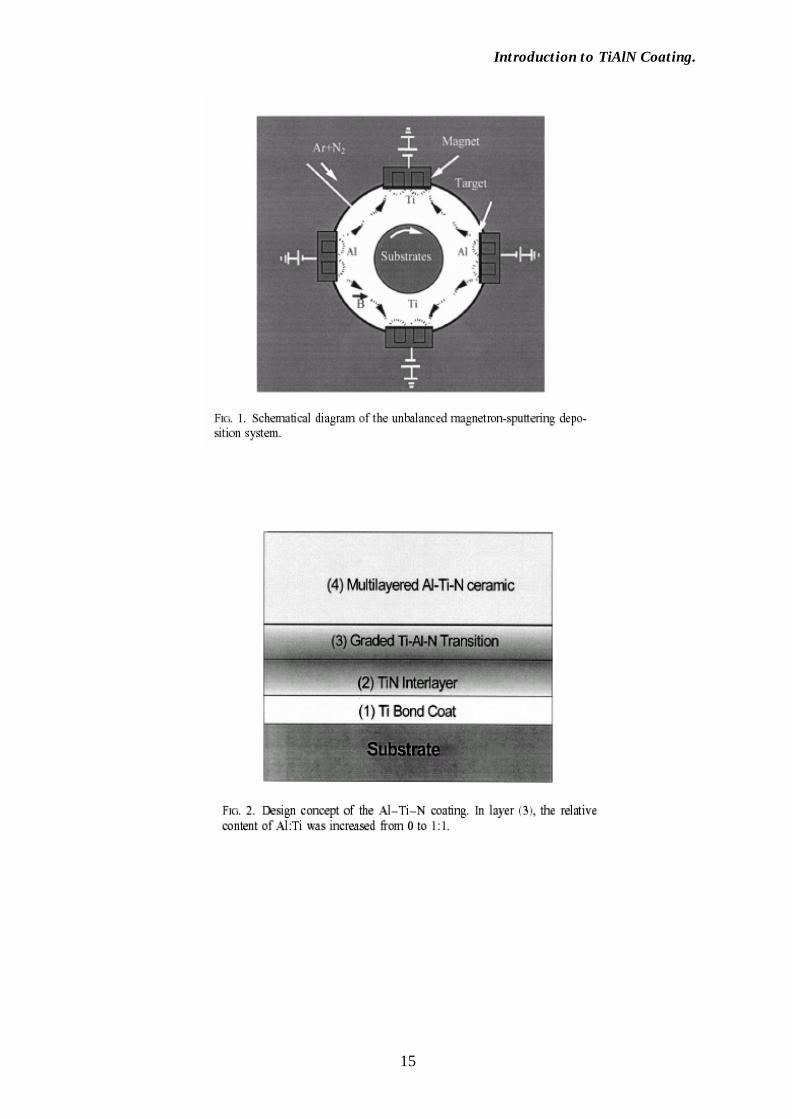
6.2. EXPERIMENTS
Coatings were deposited on WC substrates using a Teer 550 unbalanced
magnetron-sputtering system.5, 6 Figure 1 shows a schematic diagram of the deposition
chamber. Two pairs of rectangular Al and Ti targets were installed around a cylindrical
vacuum chamber. High-purity argon and nitrogen were used as the discharge and reactive
gases. The coating composition was controlled by the sputtering power applied to each
target, and an optical,
Emission monitor was used to monitor the poisoning status of the target surface.
The basic deposition conditions are tabulated in Table I. Figure 2 shows the coating
design concept. The coating starts with a Ti bond layer, followed by a TiN interlayer, then
gradually increases the Al content to form a graded Ti–Al–N transition layer, and finishes
with an Al–Ti–N top layer. Ti has good bonding strength with WC and high-speed steel
materials. This, togethe r with the TiN transition layer, ensures good adhesion strength of
Introduction to TiAlN Coating.
15

Introduction to TiAlN Coating.
16
the coating to the substrate. The top layer was processed as a multilayered structure to
achieve both high hardness and low residual stress, and also high-oxidation resistance by
alternatively depositing the Al-rich layer and Ti-rich layer, and also by using different
plasma bombardments on the growing film surface. The coating crystal structure was
analyzed by x-ray diffractometry (XRD) Using Cu K a x rays. The surface morphology
and cross sections of the coatings were studied by scanning electron microscopy. For
some samples, x-ray photoelectron spectroscopy (XPS) (VG Escalab 2201-XL) Was used
to measure the coating composition. To evaluate the micro hardness and the adhesion
strength, nano- indentation and scratch tests were carried out. Optical microscopy was
used to confirm the starting point of the scratch failure. For field testing of the coating
performance, two fluted f6 mm micro grain WC ball-nose end mills were selected as the
test tools. The WC grain size is about 0.8 mm. A MIKRON HSM700 high-speed
machining center was used for the milling experiments. The material used for the milling
tests is AISI 420 tool steel hardened to HRC52. Table II tabulates the milling field test
conditions and the main material properties.
During the tests, the flank wear of the end mills was inspected and measured at an
interval of every 5 m of machining using a Leica microscope with IMAGE database
software. The magnification used was 503. The maximum flank wear Vb8 was recorded
and analyzed. The tool life criterion is Vb850.3 mm. The total cutting distance before
reaching this criterion was used to quantify the performance of the coating and the tool
life of the tested end mill. At the end of each test, the milled surface roughness of the
specimen was measured using a Taylor–Hobson’s stylus profilometer.

Introduction to TiAlN Coating.
17
6.3. RESULTS AND DISCUSSIONS
A. Structure and composition
Figure 3 shows a typical XRD spectrum of the AlTiN coating. The coating has a
polycrystalline structure with preferential growth. Depending on the substrate bias, the
ratio of the relative intensity of the XRD peak At 2 u; 37° at 2 u; 43° varied from 0.5 to 5,
which strongly affect the mechanical properties of the coating (to be discussed later) On
the other hand, the composition and the relative content of Al to Ti are critical to the
mechanical properties and oxidation resistance of the coatings, as evidenced by the
adhesion, hardness, and oxidation temperature measurements. Stoichiometry or near
stoichiometry is necessary to achieve high hardness and good adhesion strength.
Increasing Al content can obviously increase the oxidation resistance, due to the
formation of a dense Al2O3 layer on the surface of the coating. However, this reduces the
hardness of the coating from 35–40 to 20–25 GPa. Another problem is that the Al- rich
layer has low bonding strength with the base layer, regardless of whether it is pure
metallic Ti, or ceramic TiN, resulting in poor adhesion of the coating. For this reason, a
compositional grading process is necessary. Therefore, we deposited an Al–TiN transition
layer on the TiN base layer, then a low-Al AlTiN support layer, followed by a high-Al top
layer. The transition layer starts with an Al content of 0, and gradually increases to Al: Ti;
1:1.5–2, the preset composition of the low-Al Al–Ti–N layer. The high-Al AlTiN layer
has two designs, corresponding to two compositions: Al: Ti; 1:1 and 2:1. The milling
field tests show that the second design, i.e., Al: Ti; 2:1 shows better performance, due to
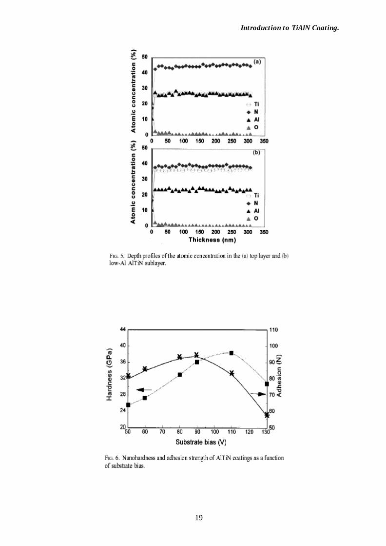
its better thermal stability. As an example, Fig. 4 shows the XPS spectrum obtained from
the coating surface, and Fig. 5 shows the depth profiles of the atomic concentration in the
top layer and the low-Al TiAlN sub layer. As designed, the top layer of the coating has a
concentration of l: Ti: N; 1:1:1.8, a near-stoichiometric composition, and the sub layer has
a concentration of Al: Ti: N; 1:1.5:1.7. This combination provides the coating with good
mechanical properties.

Introduction to TiAlN Coating.
18
Introduction to TiAlN Coating.
19

Introduction to TiAlN Coating.
20
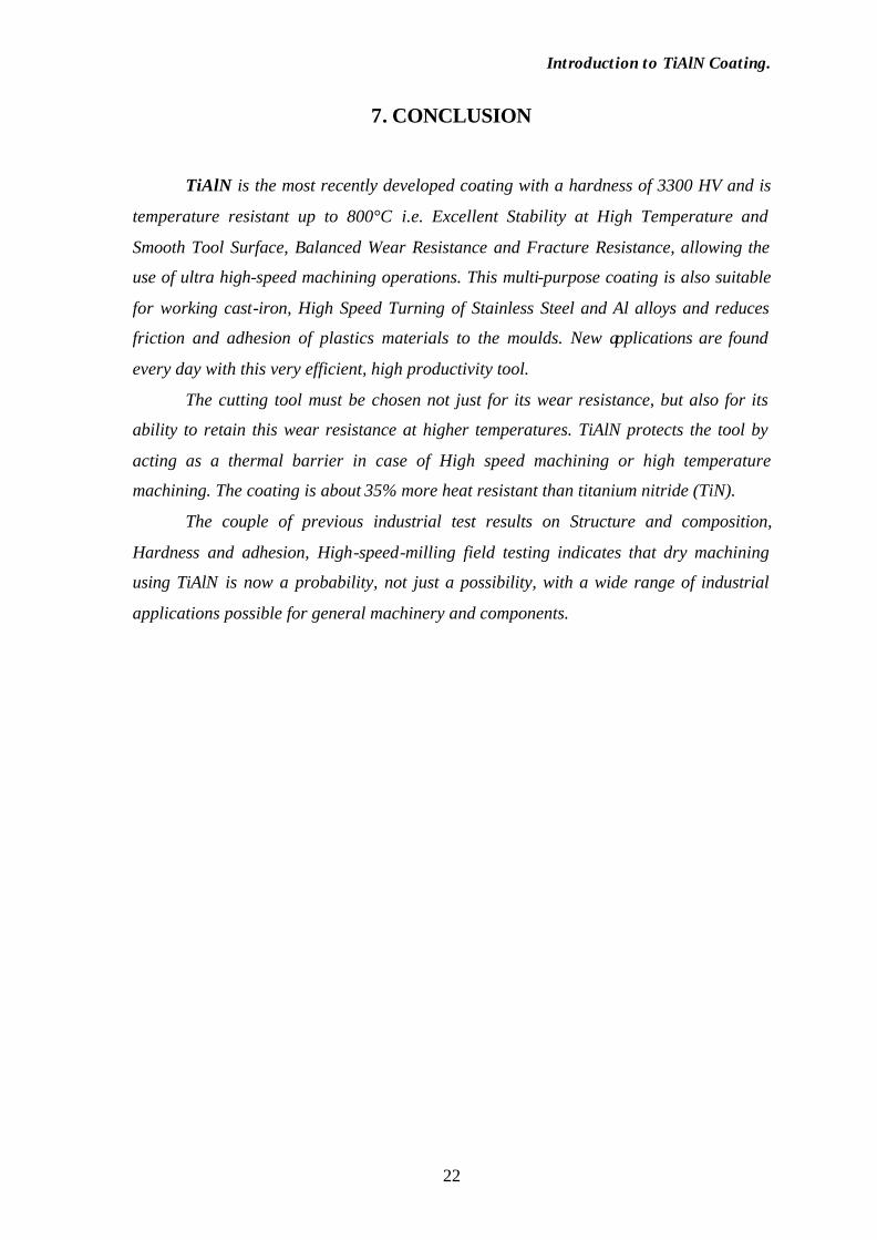
B. Hardness and adhesion
The main process parameters determining the mechanical properties of the coating
include substrate bias power, sputtering power, and discharge and reactive gas flow
rates.10–13 Sputtering power and the reactive gas flow rates determine the composition
of the coating. Provided the coating has a stoichiometric composition, the substrate bias,
which provides effective ion bombardment on the substrate surface, is the most critical
parameter to determine the crystalline structure, hardness, and adhesion. In this work, the
dc bias from 50 to 130 V was tested. Figure 6 shows the bias dependence of the hardness
and adhesion strength. With the increase of the bias power, the hardness increased
substantially, and the adhesion strength first increased and then decreased in the range of
50–110 V, due to the increase in ion bombardment. Further increasing the bias power
resulted in highly stressed films which cracked in some cases, and the adhesion strength
substantially decreased. Therefore, reducing the internal stress without sacrificing the
hardness is a key point to obtain good-quality coating.
C. High-speed-milling field testing
A total of nine cutters that are identical in geometry and tool material were field
tested at a cutting speed of 260 m/min. Two of them were uncoated, two commercially
TiAlN coated, and five graded AlTiN coated in this work. Setting the flank wear Vb850.3
mm as the end-of-life indicator, the cutting distance of all nine testing end mills were
recorded. The results are shown in Table III. Apparently, all coated tools showed much
improved tool life compared to the uncoated ones. All five cutters coated in this work
have longer tool life when compared with the commercial ones. The best one, cutter No.
1, has a tool life of 93 m, which is about 4.7 times that of the uncoated end mill.

Introduction to TiAlN Coating.
21
Besides the good mechanical properties achieved in this coating, the unique
thermal properties, which include oxidation resistance and heat insulation, play a critical
role in this performance. Here, heat insulation or low thermal conductivity of AlTiN
protects the cutting edge by insulating the tool substrate from damaging high
temperatures and by dissipating the heat to the machining chips. The surface finish of the
work material is another important end-mill performance indicator. High smoothness or
low roughness is required in many applications such as mold and die machining. Also
tabulated in Table III is the comparison of the surface roughness (Ra) achieved using the
above end mills. Cutter No. 1 coated in this work shows the best surface finish with Ra;
0.26 mm, compared with 0.40 mm of the uncoated and commercial TiAlN-coated cutters.
This surface finish satisfies the requirements for most applications in the precision
machining industry.
6.4. SUMMARY
A multilayered TiAlN coating was developed for high-speed machining tools. The
coating shows good mechanical and thermal properties. High-speed-milling field testing
shows that the tool life with these coatings is improved by a factor of 4 compared to the
uncoated tools. The surface finish achieved with our coated tools is also significantly
better.
Introduction to TiAlN Coating.
22
7. CONCLUSION
TiAlN is the most recently developed coating with a hardness of 3300 HV and is
temperature resistant up to 800°C i.e. Excellent Stability at High Temperature and
Smooth Tool Surface, Balanced Wear Resistance and Fracture Resistance, allowing the
use of ultra high-speed machining operations. This multi-purpose coating is also suitable
for working cast-iron, High Speed Turning of Stainless Steel and Al alloys and reduces
friction and adhesion of plastics materials to the moulds. New applications are found
every day with this very efficient, high productivity tool.
The cutting tool must be chosen not just for its wear resistance, but also for its
ability to retain this wear resistance at higher temperatures. TiAlN protects the tool by
acting as a thermal barrier in case of High speed machining or high temperature
machining. The coating is about 35% more heat resistant than titanium nitride (TiN).
The couple of previous industrial test results on Structure and composition,
Hardness and adhesion, High-speed-milling field testing indicates that dry machining
using TiAlN is now a probability, not just a possibility, with a wide range of industrial
applications possible for general machinery and components.

Introduction to TiAlN Coating.
23
BIBLIOGRAPHY
1. X. T. Zenga, “Horizons of TiAlN” Process Technology Division, Gintic Institute of Manufacturing Technology, Singapore, www.gintic.gov.sg
2. Sam Zhang “TiAlN Coating”, School of Mechanical and Production Engineering, Nanyang Technological University, Singapore, www.gintic.gov.sg
3. L. S. Tan “Productive improvement by AlTiN Coating” Process Technology Division, Gintic Institute of Manufacturing Tech., Singapore (27 Nov. 2000) , www.gintic.gov.sg
4. J. Vac. “Multilayered (Ti, Al) ceramic coating for high-speed machining applications”, Science. Technol A 19(4), Jul-Aug 2001.
5. R M Keskar “Productivity through Coatings on Tools”, Indian Institution of
Production Engineers, Pune Chapter, Sep. 30, 2002.
6. Don Graham, “Incremental Improvements in Coated Carbide Cutting Tools Add Up
To Important Gains in Consistency and Reliability”, Manager - Turning Programs
Carboloy Inc.
7. http://global.kyocera.com/frame/product/tool/1tools/e_tools.html
8. http://www.guhring.com/duratrans/carb_main.htm
9. http://www.microphotonics.com/mst.html
10. http://www.tribology.dti.dk/selection.html
11. http://www.tcclipper.com/Content/TiAlN Coatings.htm
12. User’s manual Balzers India Limited, Pune and http://www.Uniaxis.com
13. http://www.Sandvik.com


![MECHANICAL AND TRIBOLOGICAL PROPERTIES OF ...tribolab.mas.bg.ac.rs/proceedings/2015/137-142.pdfTiAlN/TiSiN coating. TiAlN TiAlN/TiSiN H [GPa] 25.2 38.9 E [GPa] 372.0 247.6 H3/E*2 [GPa]](https://img.pdfslide.us/doc/110x75/6090b172324120134a61f5f9/mechanical-and-tribological-properties-of-tialntisin-coating-tialn-tialntisin.jpg)