Embed Size (px)
Citation preview
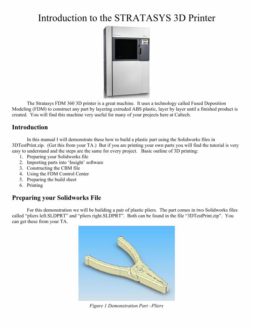
Introduction to the STRATASYS 3D Printer
The Stratasys FDM 360 3D printer is a great machine. It uses a technology called Fused Deposition Modeling (FDM) to construct any part by layering extruded ABS plastic, layer by layer until a finished product is created. You will find this machine very useful for many of your projects here at Caltech.
Introduction
In this manual I will demonstrate these how to build a plastic part using the Solidworks files in 3DTestPrint.zip. (Get this from your TA.) But if you are printing your own parts you will find the tutorial is very easy to understand and the steps are the same for every project. Basic outline of 3D printing:
1. Preparing your Solidworks file2. Importing parts into ‘Insight’ software3. Constructing the CBM file4. Using the FDM Control Center5. Preparing the build sheet6. Printing
Preparing your Solidworks File
For this demonstration we will be building a pair of plastic pliers. The part comes in two Solidworks files called “pliers left.SLDPRT” and “pliers right.SLDPRT”. Both can be found in the file “3DTestPrint.zip”. You can get these from your TA.
Figure 1 Demonstration Part –Pliers
If you are building something else besides the demo part, all the steps will be the same but the screenshots will be different. The 3D printer does not understand Solidworks files. It reads files calls called “.STL” files. This stands for Stereolithograph and is the standard file format for 3D printing. A STL file is composed of a giant list of triangles and vertices that form the geometry of the part. There is no data besides the geometry of the part. Step one is to export your Solidwork file into a .STL file.
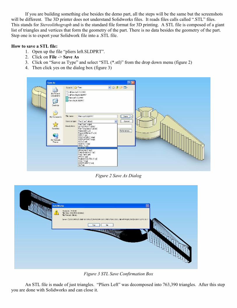
How to save a STL file:1. Open up the file “pliers left.SLDPRT”. 2. Click on File -> Save As3. Click on “Save as Type” and select “STL (*.stl)” from the drop down menu (figure 2)4. Then click yes on the dialog box (figure 3)
Figure 2 Save As Dialog
Figure 3 STL Save Confirmation Box
An STL file is made of just triangles. “Pliers Left” was decomposed into 763,390 triangles. After this step you are done with Solidworks and can close it.
Importing parts into ‘Insight’ software
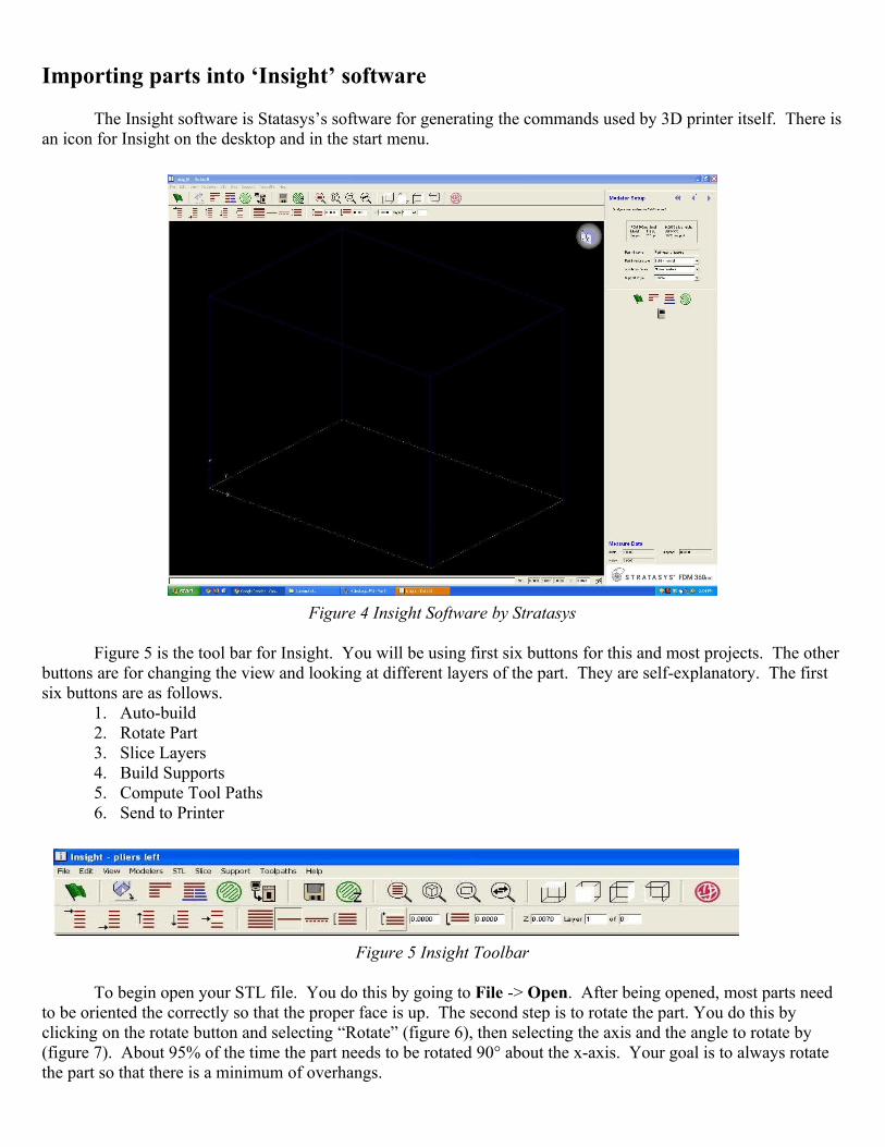
The Insight software is Statasys’s software for generating the commands used by 3D printer itself. There is an icon for Insight on the desktop and in the start menu.
Figure 4 Insight Software by Stratasys
Figure 5 is the tool bar for Insight. You will be using first six buttons for this and most projects. The other buttons are for changing the view and looking at different layers of the part. They are self-explanatory. The first six buttons are as follows.
1. Auto-build2. Rotate Part3. Slice Layers4. Build Supports5. Compute Tool Paths6. Send to Printer
Figure 5 Insight Toolbar
To begin open your STL file. You do this by going to File -> Open. After being opened, most parts need to be oriented the correctly so that the proper face is up. The second step is to rotate the part. You do this by clicking on the rotate button and selecting “Rotate” (figure 6), then selecting the axis and the angle to rotate by (figure 7). About 95% of the time the part needs to be rotated 90° about the x-axis. Your goal is to always rotate the part so that there is a minimum of overhangs.

Figure 6 Rotate Command Figure 7 Rotate Command
Constructing the CBM File
Generating the CBM file is the next step. The CBM file is a compressed file that contains all the layers, boundary paths, and tool paths data that the 3D printer needs to print your part. These files are self contained. You can use these file in the future to re-print parts with having to re-complete the all of the previous steps.
Generating the CBM file is done in three steps: (1) slicing layers, (2) building supports and, (3) computing tool paths. After the part is rotated you can click on the “Auto-Build” button (the green flag icon) and the Insight software will do all three of these things for you in a row. We will do them separately so as we can see the intermediate results. But in the future to save time you can just rotate your part and then click on “Auto-Build”.
The first step is to click on the “Slice Layers” button (third from the left in figure 5). This will cut your part into 0.1778 mm thick layers. Your part should be outlined red and look like figure 8.
Figure 8 Part after “Slicing”
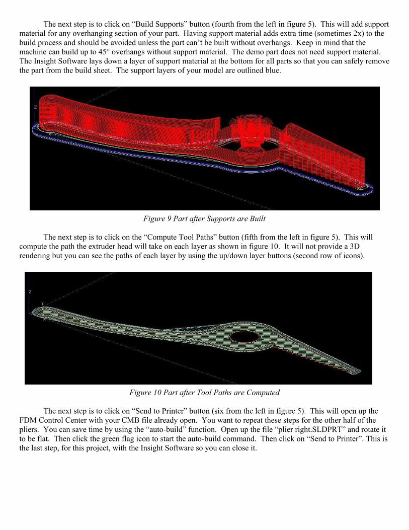
The next step is to click on “Build Supports” button (fourth from the left in figure 5). This will add support material for any overhanging section of your part. Having support material adds extra time (sometimes 2x) to the build process and should be avoided unless the part can’t be built without overhangs. Keep in mind that the machine can build up to 45° overhangs without support material. The demo part does not need support material. The Insight Software lays down a layer of support material at the bottom for all parts so that you can safely remove the part from the build sheet. The support layers of your model are outlined blue.
Figure 9 Part after Supports are Built
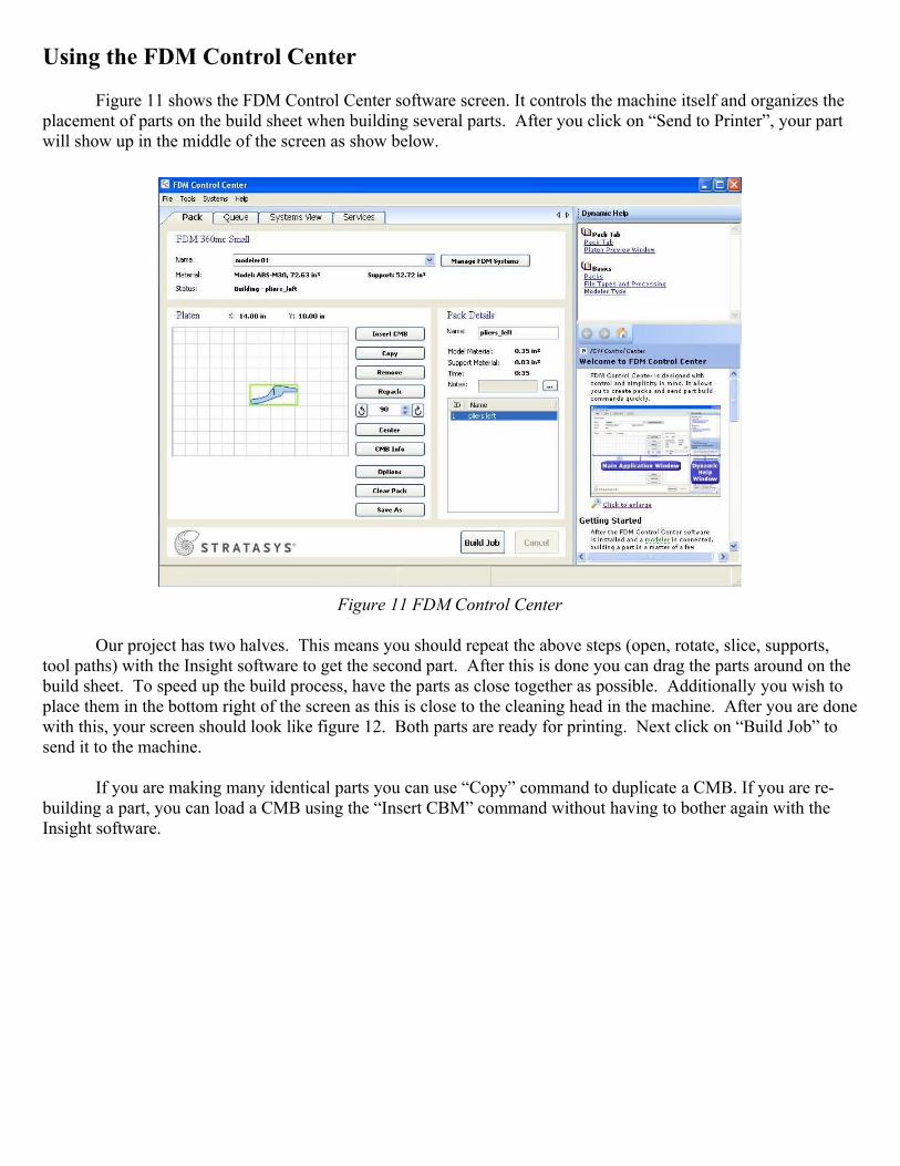
The next step is to click on the “Compute Tool Paths” button (fifth from the left in figure 5). This will compute the path the extruder head will take on each layer as shown in figure 10. It will not provide a 3D rendering but you can see the paths of each layer by using the up/down layer buttons (second row of icons).
Figure 10 Part after Tool Paths are Computed
The next step is to click on “Send to Printer” button (six from the left in figure 5). This will open up the FDM Control Center with your CMB file already open. You want to repeat these steps for the other half of the pliers. You can save time by using the “auto-build” function. Open up the file “plier right.SLDPRT” and rotate it to be flat. Then click the green flag icon to start the auto-build command. Then click on “Send to Printer”. This is the last step, for this project, with the Insight Software so you can close it.
Using the FDM Control Center
Figure 11 shows the FDM Control Center software screen. It controls the machine itself and organizes the placement of parts on the build sheet when building several parts. After you click on “Send to Printer”, your part will show up in the middle of the screen as show below.
Figure 11 FDM Control Center
Our project has two halves. This means you should repeat the above steps (open, rotate, slice, supports, tool paths) with the Insight software to get the second part. After this is done you can drag the parts around on the build sheet. To speed up the build process, have the parts as close together as possible. Additionally you wish to place them in the bottom right of the screen as this is close to the cleaning head in the machine. After you are done with this, your screen should look like figure 12. Both parts are ready for printing. Next click on “Build Job” to send it to the machine.
If you are making many identical parts you can use “Copy” command to duplicate a CMB. If you are re-building a part, you can load a CMB using the “Insert CBM” command without having to bother again with the Insight software.
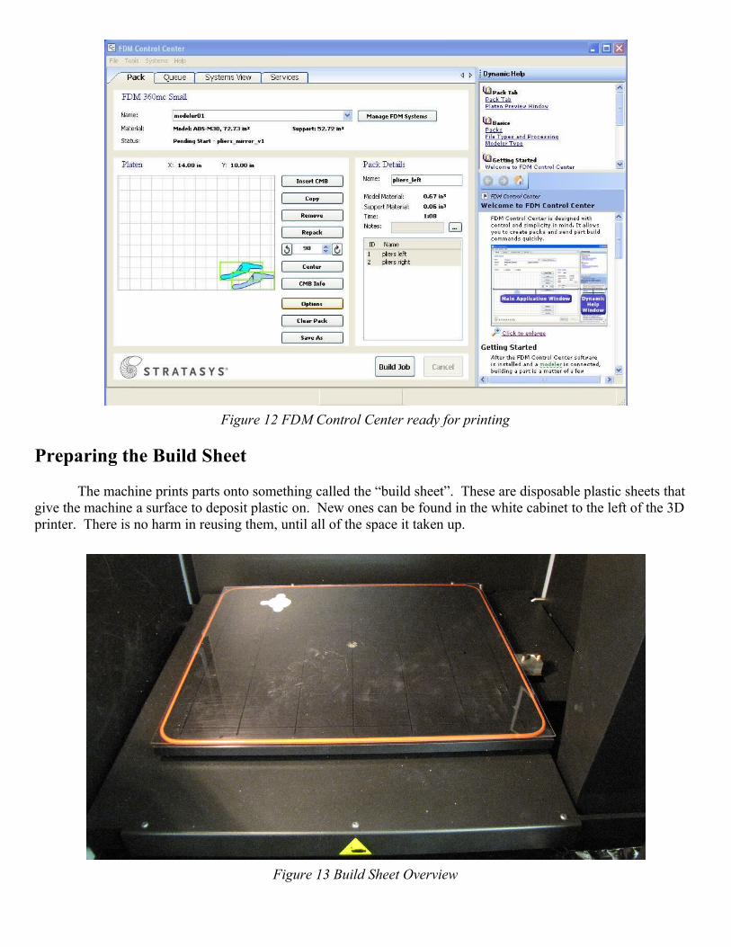
Figure 12 FDM Control Center ready for printing
Preparing the Build Sheet
The machine prints parts onto something called the “build sheet”. These are disposable plastic sheets that give the machine a surface to deposit plastic on. New ones can be found in the white cabinet to the left of the 3D printer. There is no harm in reusing them, until all of the space it taken up.
Figure 13 Build Sheet Overview
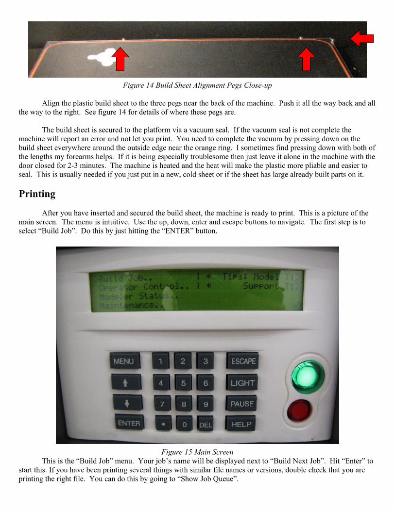
Figure 14 Build Sheet Alignment Pegs Close-up
Align the plastic build sheet to the three pegs near the back of the machine. Push it all the way back and all the way to the right. See figure 14 for details of where these pegs are.
The build sheet is secured to the platform via a vacuum seal. If the vacuum seal is not complete the machine will report an error and not let you print. You need to complete the vacuum by pressing down on the build sheet everywhere around the outside edge near the orange ring. I sometimes find pressing down with both of the lengths my forearms helps. If it is being especially troublesome then just leave it alone in the machine with the door closed for 2-3 minutes. The machine is heated and the heat will make the plastic more pliable and easier to seal. This is usually needed if you just put in a new, cold sheet or if the sheet has large already built parts on it.
Printing
After you have inserted and secured the build sheet, the machine is ready to print. This is a picture of the main screen. The menu is intuitive. Use the up, down, enter and escape buttons to navigate. The first step is to select “Build Job”. Do this by just hitting the “ENTER” button.
Figure 15 Main ScreenThis is the “Build Job” menu. Your job’s name will be displayed next to “Build Next Job”. Hit “Enter” to
start this. If you have been printing several things with similar file names or versions, double check that you are printing the right file. You can do this by going to “Show Job Queue”.
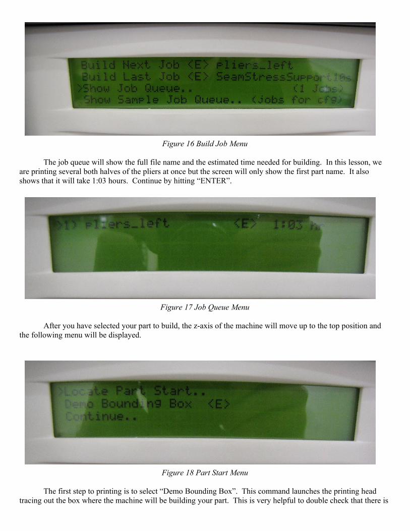
Figure 16 Build Job Menu
The job queue will show the full file name and the estimated time needed for building. In this lesson, we are printing several both halves of the pliers at once but the screen will only show the first part name. It also shows that it will take 1:03 hours. Continue by hitting “ENTER”.
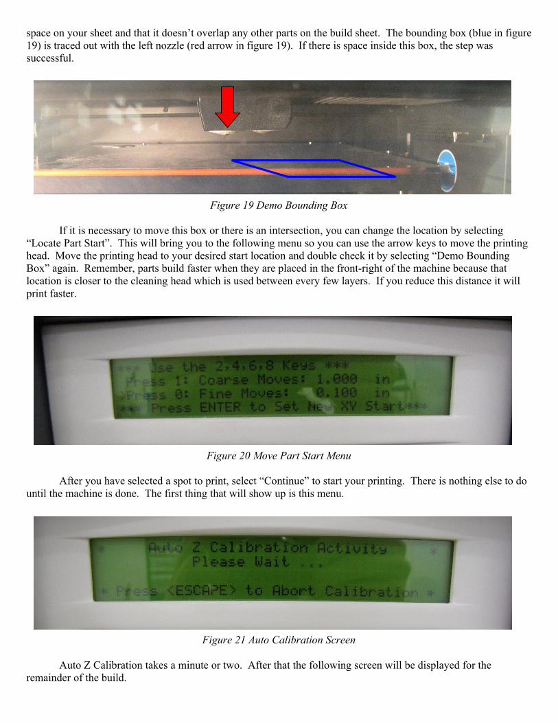
Figure 17 Job Queue Menu
After you have selected your part to build, the z-axis of the machine will move up to the top position and the following menu will be displayed.
Figure 18 Part Start Menu
The first step to printing is to select “Demo Bounding Box”. This command launches the printing head tracing out the box where the machine will be building your part. This is very helpful to double check that there is
space on your sheet and that it doesn’t overlap any other parts on the build sheet. The bounding box (blue in figure 19) is traced out with the left nozzle (red arrow in figure 19). If there is space inside this box, the step was successful.
Figure 19 Demo Bounding Box
If it is necessary to move this box or there is an intersection, you can change the location by selecting “Locate Part Start”. This will bring you to the following menu so you can use the arrow keys to move the printing head. Move the printing head to your desired start location and double check it by selecting “Demo Bounding Box” again. Remember, parts build faster when they are placed in the front-right of the machine because that location is closer to the cleaning head which is used between every few layers. If you reduce this distance it will print faster.
Figure 20 Move Part Start Menu
After you have selected a spot to print, select “Continue” to start your printing. There is nothing else to do until the machine is done. The first thing that will show up is this menu.
Figure 21 Auto Calibration Screen
Auto Z Calibration takes a minute or two. After that the following screen will be displayed for the remainder of the build.
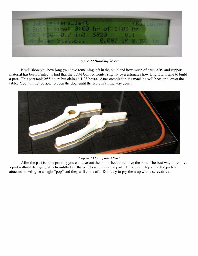
Figure 22 Building Screen
It will show you how long you have remaining left in the build and how much of each ABS and support material has been printed. I find that the FDM Control Center slightly overestimates how long it will take to build a part. This part took 0:55 hours but claimed 1:03 hours. After completion the machine will beep and lower the table. You will not be able to open the door until the table is all the way down.
Figure 23 Completed PartAfter the part is done printing you can take out the build sheet to remove the part. The best way to remove
a part without damaging it is to mildly flex the build sheet under the part. The support layer that the parts are attached to will give a slight “pop” and they will come off. Don’t try to pry them up with a screwdriver.
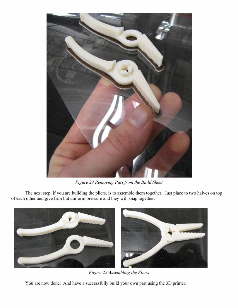
Figure 24 Removing Part from the Build Sheet
The next step, if you are building the pliers, is to assemble them together. Just place to two halves on top of each other and give firm but uniform pressure and they will snap together.
Figure 25 Assembling the Pliers
You are now done. And have a successfully build your own part using the 3D printer.
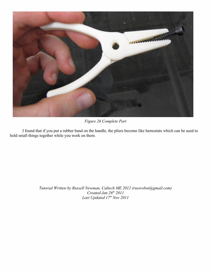
Figure 26 Complete Part
I found that if you put a rubber band on the handle, the pliers become like hemostats which can be used to hold small things together while you work on them.
Tutorial Written by Russell Newman, Caltech ME 2012 ([email protected])Created Jan 26th 2011
Last Updated 17th Nov 2011