Embed Size (px)
Citation preview
Introduction to the GM 6L80
Presented By: Steve Garrett

6L80 (RPO MYC) Introduction
The first of ten 6 speed automatics was introduced in the 2006 model year. The 6L80 (RPO MYC) is currently available in the Chevrolet Corvette, Cadillac XLR-V and the Cadillac STS-V applications. The 6L80 was introduced into several “up level” SUV applications for the 2007 model year. The new plant utilizes several industry first technical innovations and production processes and is unlike any other assembly plant in the world.

6L80 Introduction
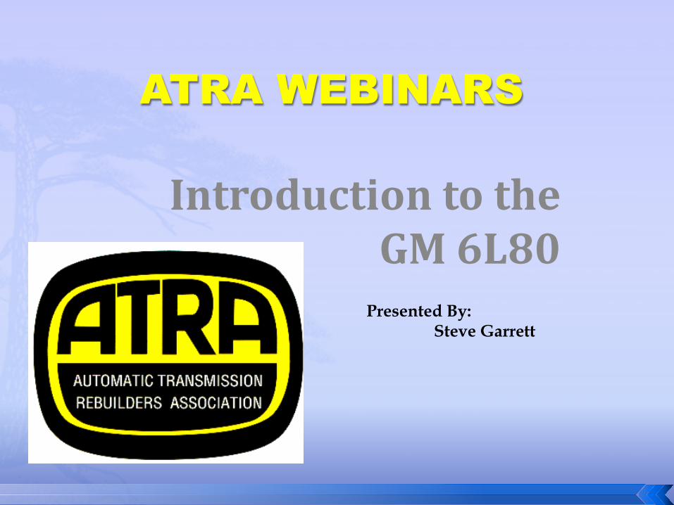
· RPO MYC · Input torque capacity 430 lb ft ( 583 Nm) · Output torque capacity 664 lb ft ( 900 Nm) · Ratios 1st – 4.02-1 2nd – 2.36-1 3rd – 1.53-1 4th – 1.15-1 5th - .85-1 6th - .67-1 · Maximum shift speed 6500 RPM · Maximum GVW 8600 lb · Maximum GCVW 14000 lb · PRNDL positions P, R, N, D, (S or M) · 2 shift solenoids used (On/Off Design), SS1,SS2 · 6 PWM controlled pressure control solenoids, PCS, PCS1, PCS2, PCS3, PCS4, PCS5, TCC · 32 bit TCM (TEHCM) mounted internal to the transmission on the valve body (Referred to as the “control solenoid valve assembly”) TCM (TEHCM) incorporates Solenoids, pressure switches, TFT and it is bolted to the valve body using 6 bolts.

6L80 Introduction
• EC3 Converter 300mm (Corvette) 258mm twin plate ( XLR-V and STS-V) • Fluid required, Dexron VI • Fluid capacity, 9.5L (10 qts.) model 6CDA, 9.7L (10.2 qts.) model 6CZA, 11.9 L (12.6 qts.) model CYA • Clutch to clutch shifts, 5 clutches, 1 sprag • Planetary (Lepelltier) Output ( Dual pinion design) • Vane style oil pump • Internally mounted TISS and TOSS hall effect type speed sensors • Internal Mode Switch (IMS) equipped • Performance Algorithm Shifting (PAS) programming • Performance Algorithm Lift Foot (PAL) programming • Sport mode and TAP shift equipped • Adaptive Strategies with fast learn capabilities • 75 transmission only DTCs Learn diagnostic process used
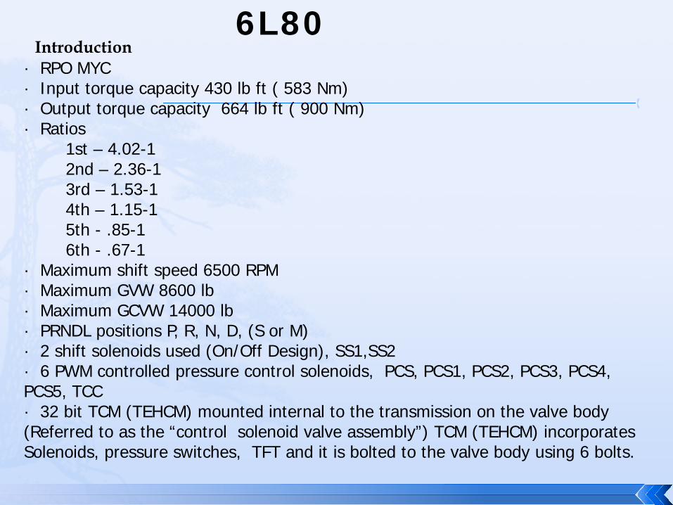
No Accumulators No Shift Valves Multifunctional Solenoids Backfill Circuits for the Clutches (Exhaust
Control) Compensator Circuits ( Clutch Release
control) Internal TCM Clutch to Clutch Shifts

* Reduced sump volumes * Higher fluid turnover rates * Increased energy densities * Reduced cooling capacity * Clutch to Clutch Shifting * 50% improvement in film strength to
reduce wear
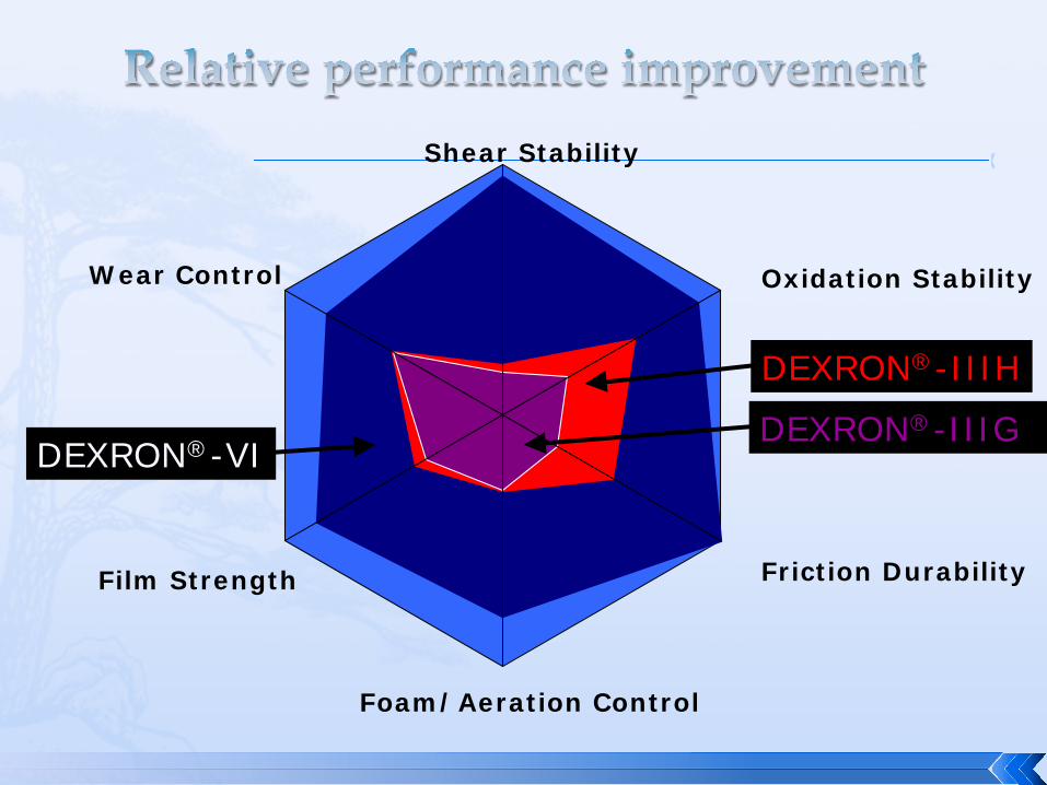
Oxidation Stability
Friction Durability
Wear Control
Foam/Aeration Control
Film Strength
Shear Stability
DEXRON®-IIIG DEXRON®-VI
DEXRON®-IIIH
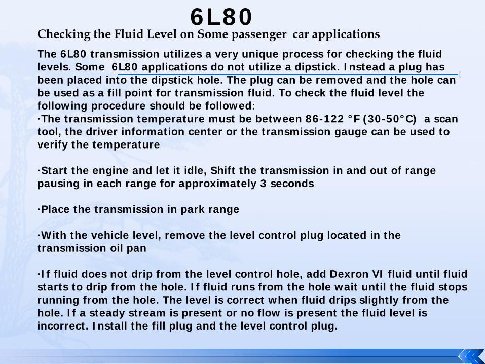
6L80 Checking the Fluid Level on Some passenger car applications The 6L80 transmission utilizes a very unique process for checking the fluid levels. Some 6L80 applications do not utilize a dipstick. Instead a plug has been placed into the dipstick hole. The plug can be removed and the hole can be used as a fill point for transmission fluid. To check the fluid level the following procedure should be followed: ·The transmission temperature must be between 86-122 °F (30-50°C) a scan tool, the driver information center or the transmission gauge can be used to verify the temperature ·Start the engine and let it idle, Shift the transmission in and out of range pausing in each range for approximately 3 seconds ·Place the transmission in park range ·With the vehicle level, remove the level control plug located in the transmission oil pan ·If fluid does not drip from the level control hole, add Dexron VI fluid until fluid starts to drip from the hole. If fluid runs from the hole wait until the fluid stops running from the hole. The level is correct when fluid drips slightly from the hole. If a steady stream is present or no flow is present the fluid level is incorrect. Install the fill plug and the level control plug.
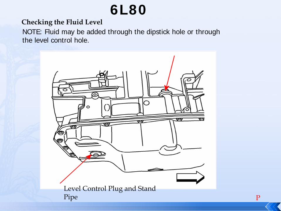
6L80 Checking the Fluid Level NOTE: Fluid may be added through the dipstick hole or through the level control hole.
Level Control Plug and Stand Pipe P
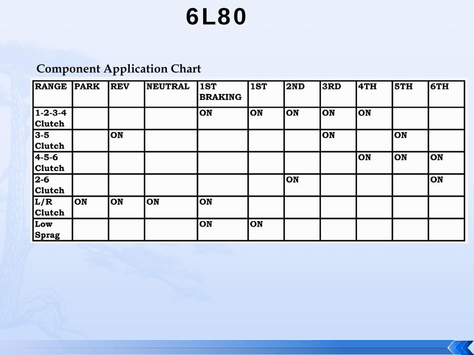
6L80
Component Application Chart

Transmission Internal components
NSBU/PRNDL/IMS Switch
Solenoid Pack/Block Assembly & TEHCM
TCM over temp protected (142c) Thermal Shutdown uses 2 thermal couples on the board. Default 3rd or 5th

6L80 Shift and Control Solenoids
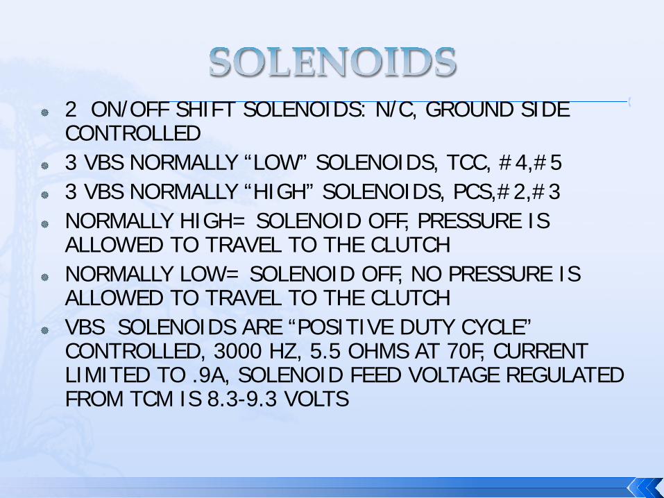
2 ON/OFF SHIFT SOLENOIDS: N/C, GROUND SIDE CONTROLLED
3 VBS NORMALLY “LOW” SOLENOIDS, TCC, #4,#5 3 VBS NORMALLY “HIGH” SOLENOIDS, PCS,#2,#3 NORMALLY HIGH= SOLENOID OFF, PRESSURE IS
ALLOWED TO TRAVEL TO THE CLUTCH NORMALLY LOW= SOLENOID OFF, NO PRESSURE IS
ALLOWED TO TRAVEL TO THE CLUTCH VBS SOLENOIDS ARE “POSITIVE DUTY CYCLE”
CONTROLLED, 3000 HZ, 5.5 OHMS AT 70F, CURRENT LIMITED TO .9A, SOLENOID FEED VOLTAGE REGULATED FROM TCM IS 8.3-9.3 VOLTS
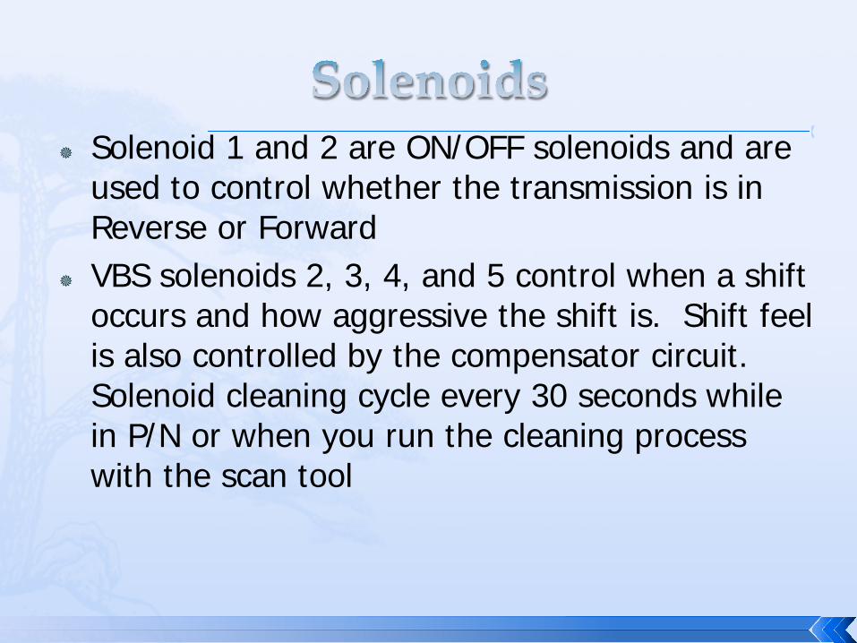
Solenoid 1 and 2 are ON/OFF solenoids and are used to control whether the transmission is in Reverse or Forward
VBS solenoids 2, 3, 4, and 5 control when a shift occurs and how aggressive the shift is. Shift feel is also controlled by the compensator circuit. Solenoid cleaning cycle every 30 seconds while in P/N or when you run the cleaning process with the scan tool
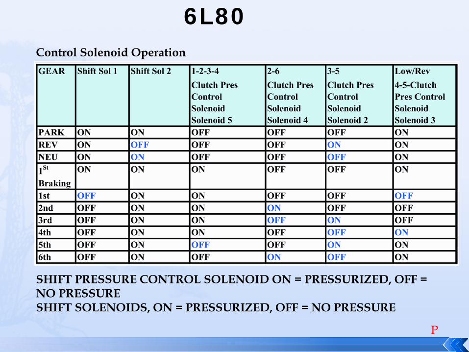
6L80 Control Solenoid Operation
SHIFT PRESSURE CONTROL SOLENOID ON = PRESSURIZED, OFF = NO PRESSURE SHIFT SOLENOIDS, ON = PRESSURIZED, OFF = NO PRESSURE
P
6L80 Introduction
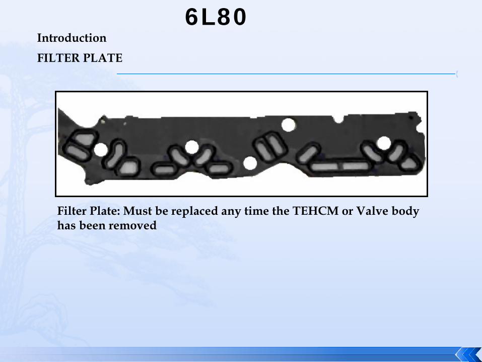
Filter Plate: Must be replaced any time the TEHCM or Valve body has been removed
FILTER PLATE
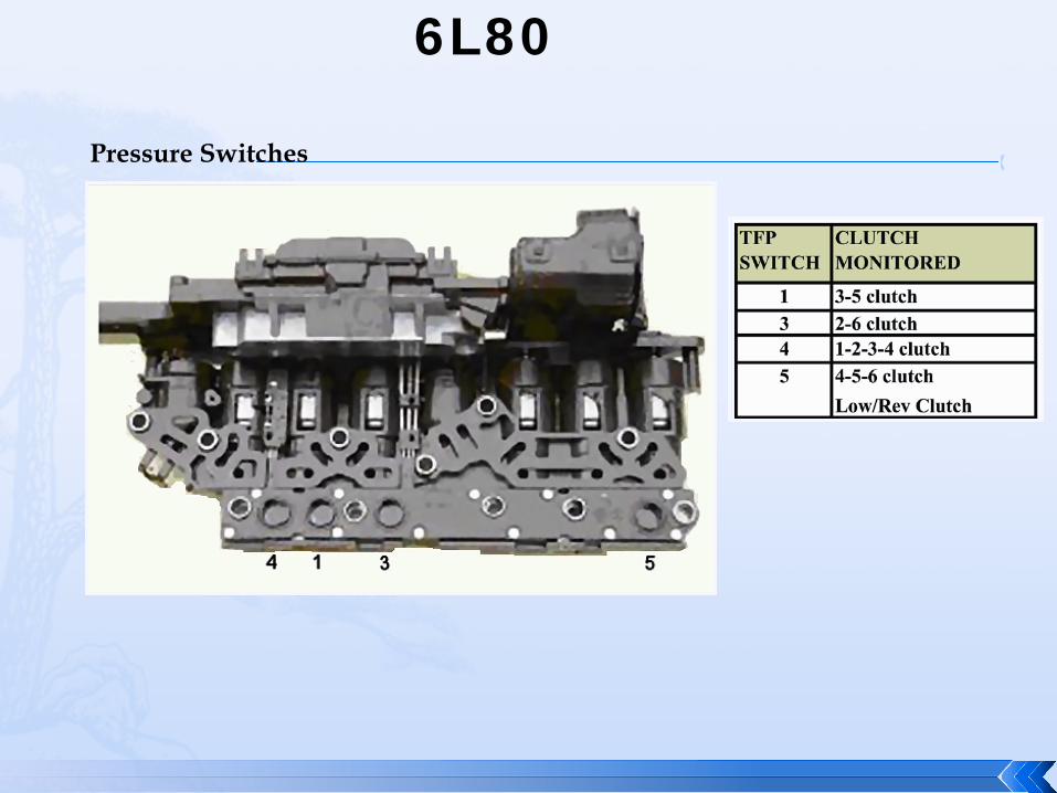
6L80
Pressure Switches
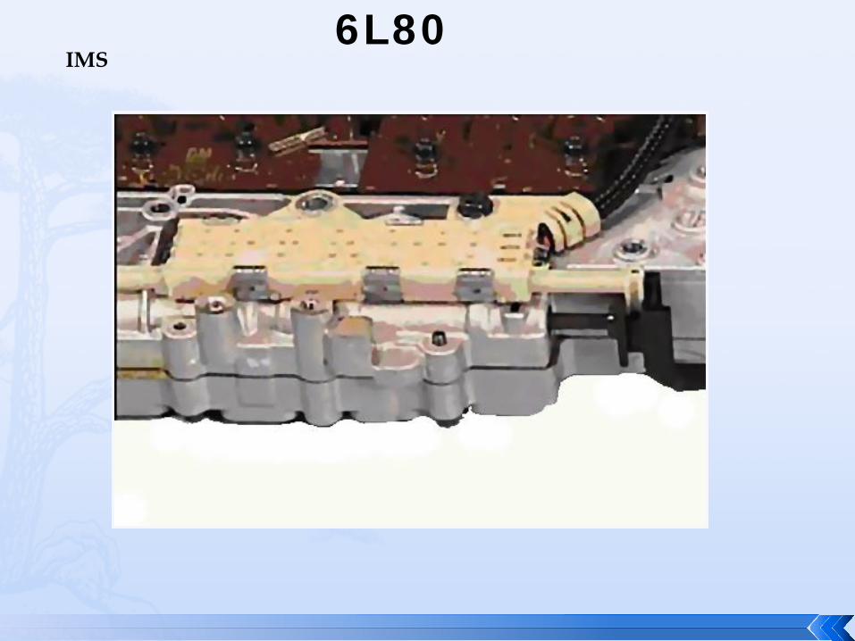
6L80 IMS

6L80 IMS Operation
High = 12 volts Low = 0 volts Not all applications utilize all ranges shown
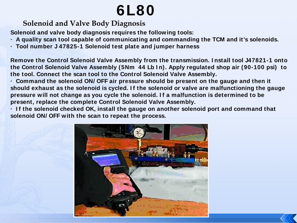
6L80 Solenoid and Valve Body Diagnosis
Solenoid and valve body diagnosis requires the following tools: · A quality scan tool capable of communicating and commanding the TCM and it’s solenoids. · Tool number J 47825-1 Solenoid test plate and jumper harness Remove the Control Solenoid Valve Assembly from the transmission. Install tool J47821-1 onto the Control Solenoid Valve Assembly (5Nm 44 Lb In). Apply regulated shop air (90-100 psi) to the tool. Connect the scan tool to the Control Solenoid Valve Assembly. · Command the solenoid ON/OFF air pressure should be present on the gauge and then it should exhaust as the solenoid is cycled. If the solenoid or valve are malfunctioning the gauge pressure will not change as you cycle the solenoid. If a malfunction is determined to be present, replace the complete Control Solenoid Valve Assembly. · If the solenoid checked OK, install the gauge on another solenoid port and command that solenoid ON/OFF with the scan to repeat the process.
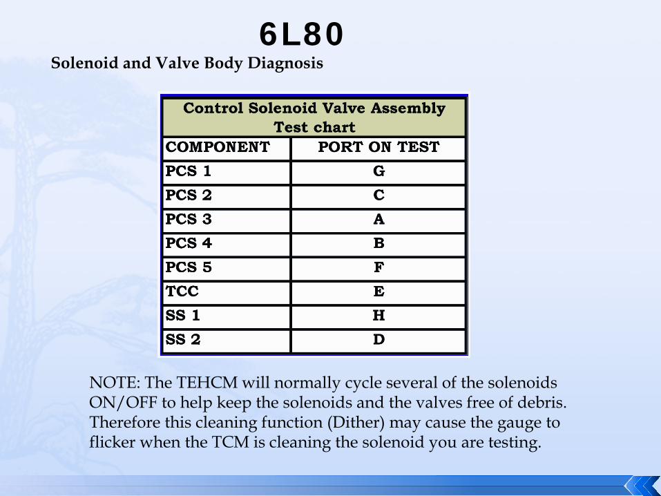
6L80 Solenoid and Valve Body Diagnosis
NOTE: The TEHCM will normally cycle several of the solenoids ON/OFF to help keep the solenoids and the valves free of debris. Therefore this cleaning function (Dither) may cause the gauge to flicker when the TCM is cleaning the solenoid you are testing.
23
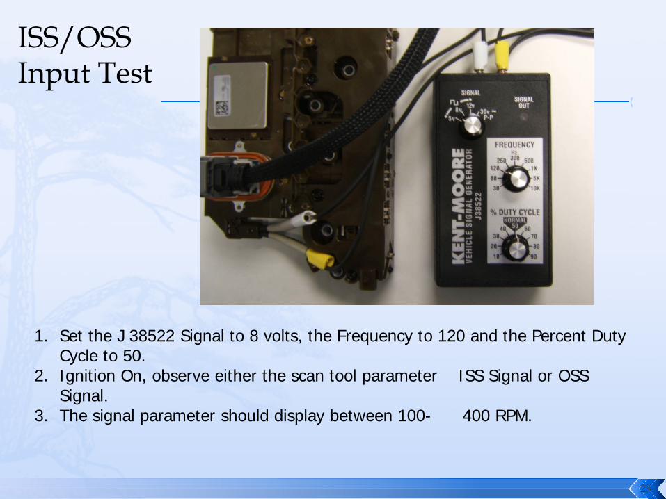
1. Set the J 38522 Signal to 8 volts, the Frequency to 120 and the Percent Duty Cycle to 50.
2. Ignition On, observe either the scan tool parameter ISS Signal or OSS Signal.
3. The signal parameter should display between 100- 400 RPM.
ISS/OSS Input Test

6L80 Adaptive Learning
The 6L80 is fully equipped with several adaptive learning strategies. As with some other GM applications you will need to erase the adaptive values and perform a “Fast Learn” prior to operating the vehicle. Adapts and fast learn procedures should be perform if any of the following occur: · Internal Transmission repairs have been performed · The valve body was replaced · The Control Solenoid valve assembly was replaced · The TCM was recalibrated · Internal repairs were performed that could effect shift quality NOTE: Fast learn is not required if a GM New or Rebuilt 6L80 is used. The transmission is fast learned prior to it being shipped from the plant
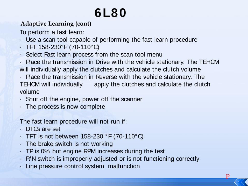
6L80 Adaptive Learning (cont) To perform a fast learn: · Use a scan tool capable of performing the fast learn procedure · TFT 158-230°F (70-110°C) · Select Fast learn process from the scan tool menu · Place the transmission in Drive with the vehicle stationary. The TEHCM will individually apply the clutches and calculate the clutch volume · Place the transmission in Reverse with the vehicle stationary. The TEHCM will individually apply the clutches and calculate the clutch volume · Shut off the engine, power off the scanner · The process is now complete The fast learn procedure will not run if: · DTCs are set · TFT is not between 158-230 °F (70-110°C) · The brake switch is not working · TP is 0% but engine RPM increases during the test · P/N switch is improperly adjusted or is not functioning correctly · Line pressure control system malfunction
P

6L80 Pass-thru Connector ID
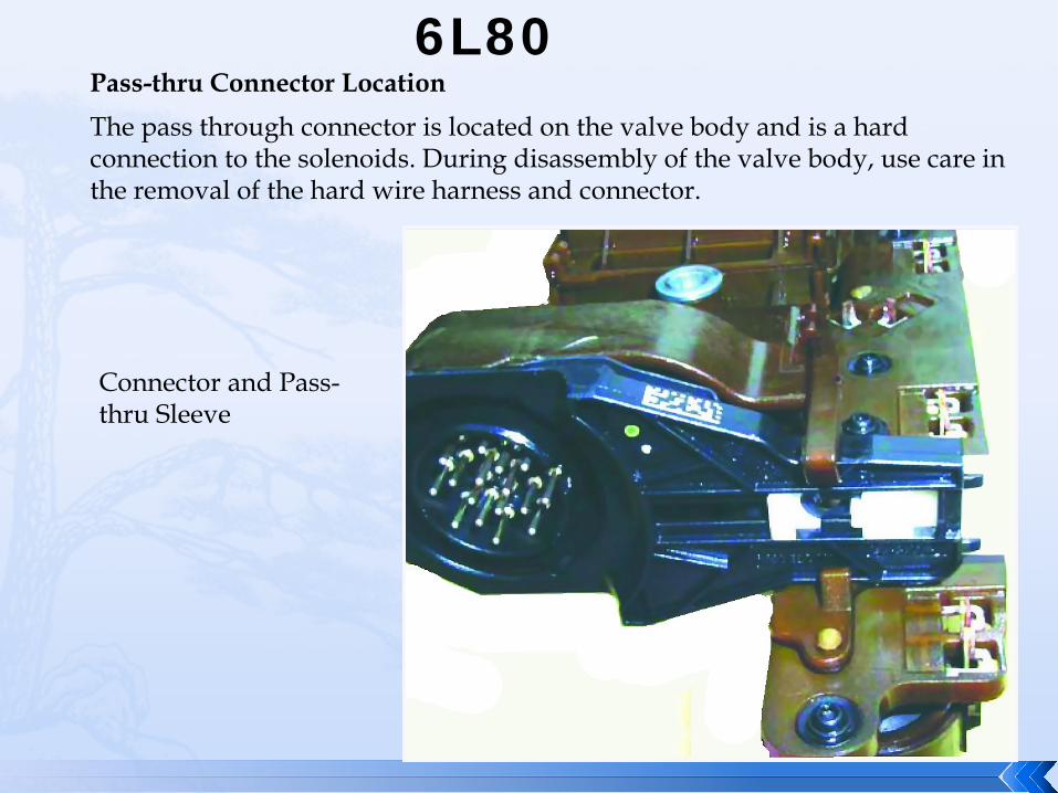
6L80 Pass-thru Connector Location The pass through connector is located on the valve body and is a hard connection to the solenoids. During disassembly of the valve body, use care in the removal of the hard wire harness and connector.
Connector and Pass-thru Sleeve

Thank you for Attending
If you have any questions or comments please raise your hand… Or email [email protected] We hope you enjoyed today's presentation!