Embed Size (px)
Citation preview
INTRODUCTION TO INTRODUCTION TO TELECOMMUNICATIONTELECOMMUNICATION
INTRODUCTION TO INTRODUCTION TO TELECOMMUNICATIONTELECOMMUNICATION
SHAKEEL AHMADSHAKEEL AHMAD

ALREADY STUDIED
• SIGNALS BASICS• PCM

TODAY ON TODAY ON 21-02-200421-02-2004
TODAY ON TODAY ON 21-02-200421-02-2004
Transmission Media for TrunksTransmission Media for Trunks
Media Types Open Wire Pairs Twisted Pair Wires Coaxial Cable Microwave Links Submarine Cables Satellite Communications Optical Fiber
Open Wire Pairs
Used in early years of telephony, more of history now.
A pair consists of two open wires suspended on telephone poles.
The wires are separated by approximately 1 ft to minimize capacitance.
Glass insulators mounted on wooden crossbeams of the telephone pole suspend the wires between poles
Open Wire Pairs Open wire is usually made of steel,
coated with copper Steel is used for the strength necessary
to withstand varying weather conditions and to withstand the suspension weight of the wirebetween poles
Distance between repaeters upto 50kms No. of channels over a single pair – 12
Open Wire Pairs Frequency range up to 160kHz Disadvantages:
Bulky and unsightly Affected by weather conditions
i.e. large leakage with insulators Severe cross-talk High radiation at the high frequencies
Twisted-Pair Wires Twisted-Pair Wires
Insulated Pairs of copper wire Insulated Pairs of copper wire bundled together bundled together
Individual pairs of wires twisted Individual pairs of wires twisted together to minimize crosstalktogether to minimize crosstalk
Cables can contain several Cables can contain several hundreds of twisted pairs in hundreds of twisted pairs in different gages.different gages.
Laid in cities undergroundLaid in cities underground
Twisted-Pair WiresTwisted-Pair Wires
Suffer from cross-talk Suffer from cross-talk because of pairs being because of pairs being bound closely.bound closely.
Due to the small Due to the small diameter of the wires, diameter of the wires, resistance contributes resistance contributes significantly to signal losssignificantly to signal loss
Twisted-Pair WiresTwisted-Pair Wires
Repeaters required every Repeaters required every 3 to 6.5 km3 to 6.5 km
Used for short haul trunksUsed for short haul trunks Voice channels over a Voice channels over a
single pair 12-120single pair 12-120 Frequency range up to Frequency range up to
1MHz1MHz
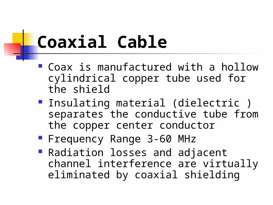
Coaxial Cable Coax is manufactured with a hollow
cylindrical copper tube used for the shield
Insulating material (dielectric ) separates the conductive tube from the copper center conductor
Frequency Range 3-60 MHz Radiation losses and adjacent channel
interference are virtually eliminated by coaxial shielding
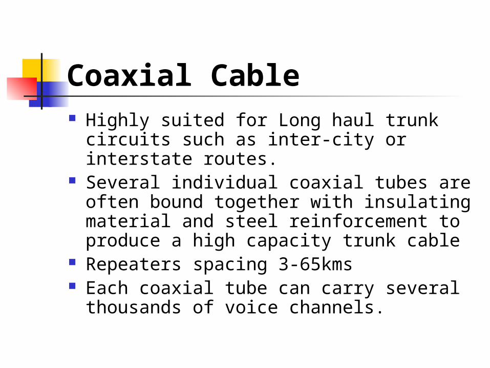
Coaxial Cable Highly suited for Long haul trunk circuits
such as inter-city or interstate routes. Several individual coaxial tubes are
often bound together with insulating material and steel reinforcement to produce a high capacity trunk cable
Repeaters spacing 3-65kms Each coaxial tube can carry several
thousands of voice channels.
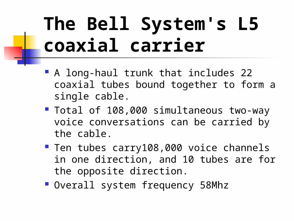
The Bell System's L5 coaxial carrier A long-haul trunk that includes 22 coaxial
tubes bound together to form a single cable.
Total of 108,000 simultaneous two-way voice conversations can be carried by the cable.
Ten tubes carry108,000 voice channels in one direction, and 10 tubes are for the opposite direction.
Overall system frequency 58Mhz
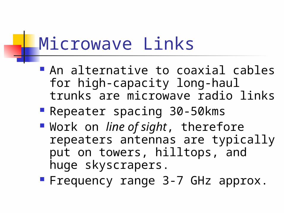
Microwave Links An alternative to coaxial cables for
high-capacity long-haul trunks are microwave radio links
Repeater spacing 30-50kms Work on line of sight, therefore
repeaters antennas are typically put on towers, hilltops, and huge skyscrapers.
Frequency range 3-7 GHz approx.
Microwave Links Affected by weather conditions
such as rain resulting in fading Can cause radio interference High velocity of propagation
minimizing the time delay No. of channels in thousands per
route
Microwave Links Advantages
Fewer repeaters are necessary for amplifying signals
Underground facilities are not necessary
Multiple channels can be transmitted over a single link
Microwave Links
Advantages Minimal delay times Minimal cross talk Fewer repeaters mean increased reliability and less maintenance
Submarine Cables Submarine cables are coaxial cables
specially designed to withstand the rugged oceanic floor conditions throughout the world
First voice-grade cable was laid across the Atlantic Ocean floor in 1956. The TAT-l (Transatlantic) Cable System, developed by AT&T, spanned a distance of 2200 nautical miles
Submarine Cables Construction of the cable includes
several layers of insulation and armored steel reinforcement surrounding the conductor to protect it from corrosion, temperature changes, and leakage
Repeaters are constructed in a similar manner to prevent the damage of internal circuitry
Submarine Cables Important factors
The cable must be protected from saltwater corrosion and leakage
Suboceanic terrain conditions and ocean depth must be considered
Temperature and pressure changes from sea level to ocean floor must be determined
Submarine Cables
Important factors The weight of cable material and
rate of descent to the oceanic floor are critical parameters.
Off-coast trenches must be dug in shallow waters to bury and protect the cable from fishing trawlers and anchors
Submarine Cables Electrical circuits must be
environmentally tested at temperature extremes exceeding those of the ocean floor
Repeater units must be x-ray tested for faulty welds and leaks
Performance tests must be exercised constantly while laying cable to determine immediately the location of a fault
Submarine Cables First generation laid in 1950s
48 voice channels Repeaters at 39 nautical miles Overall bandwidth 164 kHz
Submarine Cables Latest generation
Overall bandwidth 28Mhz 4000 Voice channels
Now fiber optic cables being installed with half the size, one third the weight and double the capacity of existing coaxial cable
Satellite Communications First satellite Intelsat I (called Early Bird)
was designed to handle 240 voice channels (in 1965)
Telephone and television broadcast signals are beamed up to the satellite from an earth through the use of a large, highly directive microwave dish antenna that is synchronized to the position of the satellite
Satellite Communications
A device called a transponder is used on board the satellite to receive the weak microwave signal, amplify and condition it, and retransmit the signal back to another earth station in a different location on earth
Satellite Communications To prevent the transponder's
strong transmitted signal from interfering with the earth station's weak received signal, most commercial satellite links separate, transmit, and receive carrier frequencies by about 2 GHz
Satellite Communications
Earth stations typically transmit their signals to satellites on carrier frequencies in the 6-GHz band, ranging from 5.92 to 6.43Ghz (the up-link frequency).
The satellite's transponder down-converts these signals to a 4-GHz band, ranging from 3.7 to 4.2 GHz. (the down-link frequencies)
Satellite Communications Geo-synchronous or geo-
stationary satellites positioned at approximately 22,300 miles above the equator
Satellite Communications
At an altitude of 22,300 miles, 40% of the Earth is exposed. The satellite's antenna is designed to emit a radiation pattern that covers this entire exposed portion
Satellite Communications
Satellites positioned in geo-synchronous orbit, 120° apart from each other, can cover the entire surface of the earth
Subject to long delays
Satellite Communications
Much lower cost per channel than submarine cable for transatlantic communications
600 channels per transponders, 12 transponders per sartellite
Optical Fiber Material composition types (cladding
& core) Glass cladding and glass core Plastic cladding and glass core Plastic cladding and plastic core
Special protection required, the extent of which depends upon application used.
No. of voice channels in thousands
Optical Fiber Not subject to interference or tapping
making it secure as well Modern day requirements of several
gigabits per sec can be accommodated
Repeaters spacing possible over 100 km because of less loss
Optic fiber Cables substantially lighter than copper cables with same capacity
Optical Fiber Optic fiber cable has a longer life span than
copper because it is more resistant to corrosion
Interfacing cost is higher for electronic facilities which are to be converted into optics.
Difficult to splice Remote powering is a problem, sometimes
metallic conductors are bundled in the cable for the purpose

Thank You