Embed Size (px)
Citation preview

1 © 2013 The MathWorks, Inc.
Introduction to Simulink, Stateflow,
and Simscape
By Paul Peeling
MathWorks

2
Key Technologies for Embracing Complexity
Model-Based Design
Multi-Domain Modelling
Code Generation

3
Two Engineering Challenges
Shift schedule optimisation of an
automatic transmission controller
Modelling and control of an
inverted double pendulum

4
Modelling Automatic Transmission

5
Modelling Automatic Transmission in Simulink

6
Blocks in Simulink
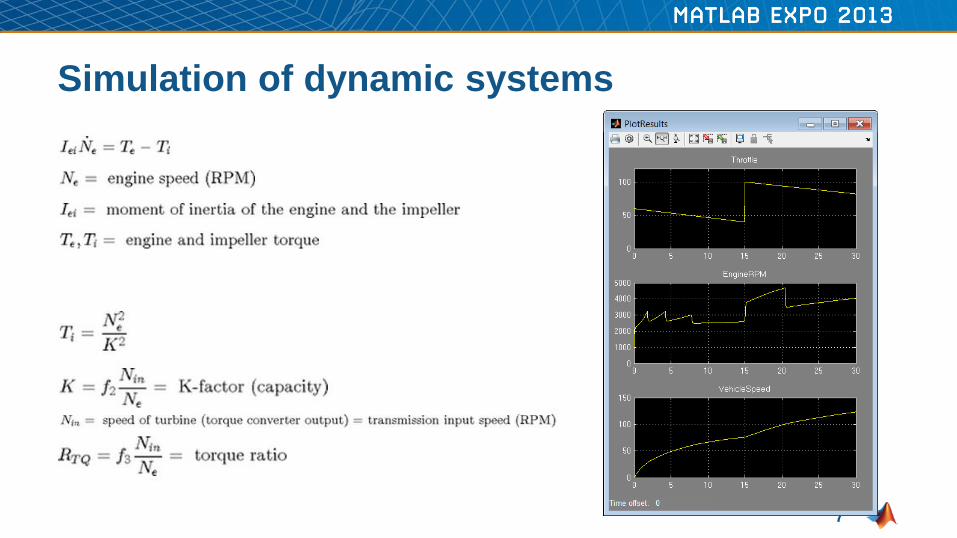
Fundamental blocks
Subsystems
Other Simulink Models
MATLAB Code
DLLs
Stateflow Charts
Simscape Components
…
7
Simulation of dynamic systems
8
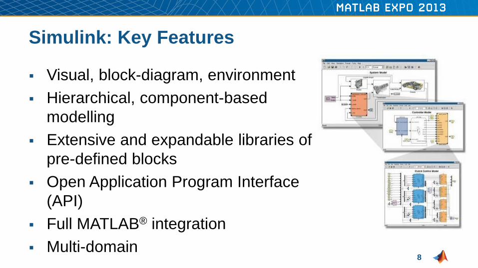
Simulink: Key Features
Visual, block-diagram, environment
Hierarchical, component-based
modelling
Extensive and expandable libraries of
pre-defined blocks
Open Application Program Interface
(API)
Full MATLAB® integration
Multi-domain

9
Stateflow for Complex Logic
When to use Stateflow?
Model instantaneous
changes in dynamic
systems
– Changes in state
– Events
Finite state machines
Flow diagrams

10
Stateflow Overview
Extend Simulink with a design environment for
developing state machines and flow charts
Design systems containing control, supervisory, and
mode logic
Describe logic in a natural and understandable form
with deterministic execution semantics

11
Stateflow: Key Features
Defines functions
– Procedurally, using MATLAB
– Graphically, using flow diagrams
– In tabular form, with truth tables
Provides language elements,
hierarchy, and parallelism
Animates Stateflow® charts
Incorporates custom and legacy C
code
Performs static and run-time checks

12
Conclusions
Simulink and Stateflow provide:
A powerful environment for modelling real processes...
in a modular fashion...
and are fully integrated with the MATLAB environment
for extensive design & analysis capability

13
Physical Modelling
Physical
Hardware
S1
S2 S3
Software and
Algorithms
P T T
A B
PID + -
if (..)
x = …
else
x =
Inputs and outputs, state
charts, algorithms, …
Physical devices

14
What does this model represent?

15
Modelling an electrical circuit in Simulink
Step 1: figure out the equations
Step 2: build the model

16
Differential equation
Algebraic equation
Differential Algebraic Equation

17
Constructed by the
Simscape solver
Component equations
Modeling an electrical circuit in Simscape
18
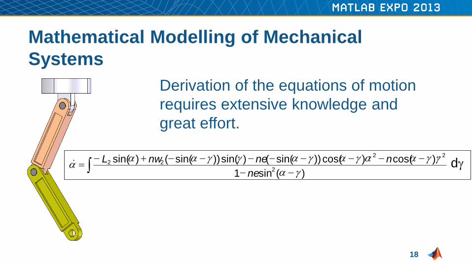
Mathematical Modelling of Mechanical
Systems
Derivation of the equations of motion
requires extensive knowledge and
great effort.
- -
- - - - - - - - + - =
) ( sin 1
) cos( ) cos( )) sin( ( ) sin( )) sin( ( ) sin( 2
2 2
2 2
g a
g g a a g a g a g g a a a
ne
n ne nw L & & & dg

19
With SimMechanics
Revolute
Joint1
Revolute
Joint2
Joints Bodies
Fixture
Link1
Link2 +
SimMechanics Model

20
Physical Systems in Simulink®
Sim
Mechanic
s™
Mechanical dynamics (3-D)
Sim
Drivelin
e™
Drivetrain systems (1-D)
Sim
Hydra
ulic
s®
Fluid power and control Multidomain physical systems
Electrical power systems
Sim
Pow
erS
yste
ms
™
Sim
Ele
ctr
onic
s™
Electromechanical and
electronic systems
Simscape™

21
Simscape Key Features
Library of foundation physical modelling
building blocks
– Mechanical, electrical, hydraulic,…
Simscape language source provided
Signals and parameters with units, and
automatic unit conversion
Physical network solver technology
designed for physical systems
Integrated with Simulink to support
complete system modelling (physical
system plus algorithms)
Convert to C code for deployment
P A T B


![ADAPTIVE CRUISE CONTROL OF A SIMSCAPE DRIVELINE …jestec.taylors.edu.my/Vol 16 issue 1 February 2021/16_1_47.pdflongitudinal vehicle dynamics using Simscape Driveline library [36]](https://img.pdfslide.us/doc/110x75/612eb33c1ecc51586942faa7/adaptive-cruise-control-of-a-simscape-driveline-16-issue-1-february-202116147pdf.jpg)