Embed Size (px)
Citation preview
1
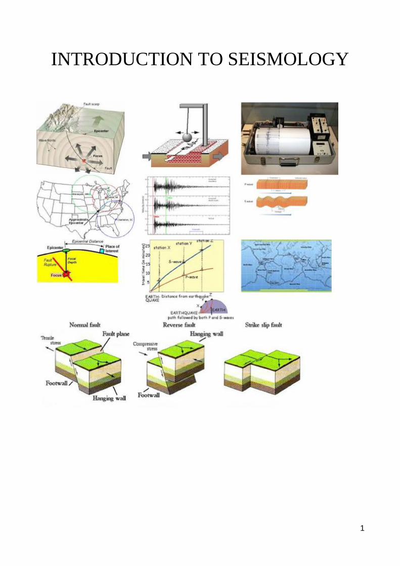
INTRODUCTION TO SEISMOLOGY
2
Earthquake Engineering
• Earthquake engineering can be defined as the branch of engineering devoted to
mitigating earthquake hazards.
• Earthquake engineering involves planning, designing, constructing and
managing earthquake-resistant structures and facilities.
3
1.1 Earth's Interior
• The earth's radius is 6371 km.
• Direct drilling went only to 13 km.
• Materials brought up by volcanoes are only from the outer 200 km.
• Physical conditions are brought about by computer modeling, laboratory
experiments and data generated from seismic waves generated by earthquakes
and nuclear explosions.
Major layers of the Interior
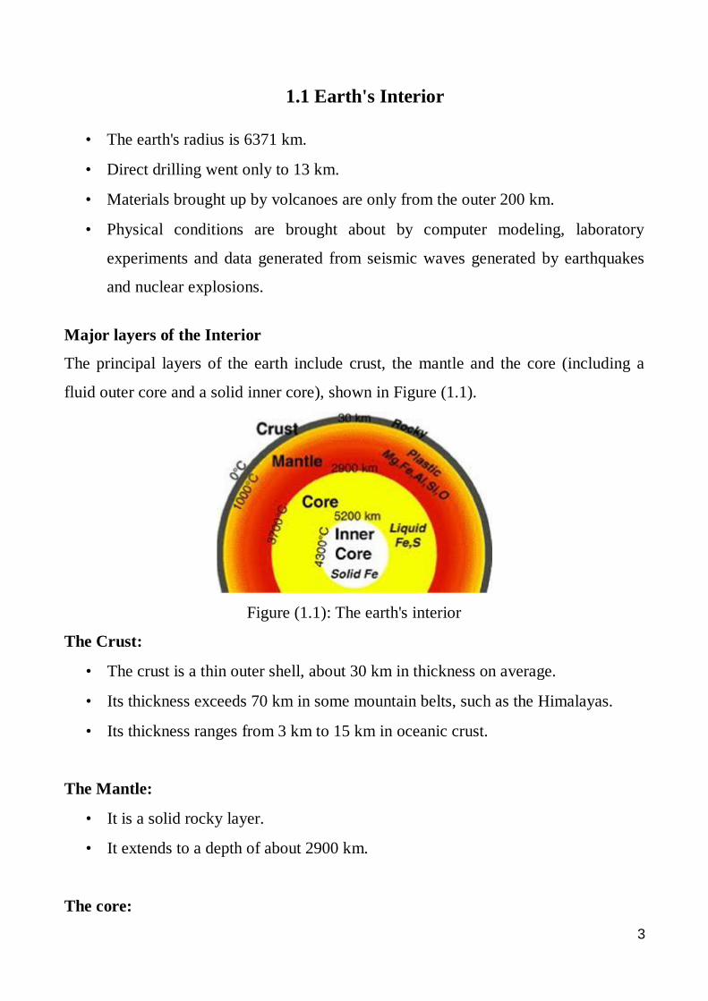
The principal layers of the earth include crust, the mantle and the core (including a
fluid outer core and a solid inner core), shown in Figure (1.1).
Figure (1.1): The earth's interior
The Crust:
• The crust is a thin outer shell, about 30 km in thickness on average.
• Its thickness exceeds 70 km in some mountain belts, such as the Himalayas.
• Its thickness ranges from 3 km to 15 km in oceanic crust.
The Mantle:
• It is a solid rocky layer.
• It extends to a depth of about 2900 km.
The core:
4
Inner core:
• Its radius is 1220 km.
• The inner core is solid due to generated pressure.
• It is made of iron.
Outer Core:
• Its radius is about 3400 km.
• It is made of iron mixed with other elements.
5
1.2Tectonic Plates
Stress that causes an earthquake is created by a movement of almost rigid plates,
called tectonic plates, which fit together and make up the outer shell of the earth
(crust). These plates float on a dense, liquid layer beneath them. These plates move at
such a slow rate (approximately the same rate as a fingernail grows), which is not
perceptible.
Over time, however, this small movement can build up enough stress to produce
earthquakes.
Most frequently earthquakes occur on or near the edges of the plates where stress is
most concentrated, such earthquakes are called interplate earthquakes.
A significant number of earthquakes, including some large and damaging ones, do
occur within the plates; these earthquakes are known as intraplate earthquakes.
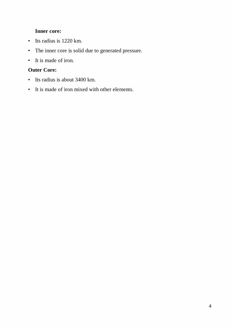
Figure (1.2) shows various tectonic plates that constitute the surface of the earth.
Figure (1.2): Various tectonic plates that constitute the surface of the earth
6
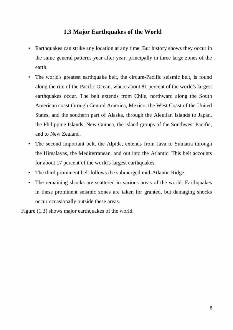
1.3 Major Earthquakes of the World
• Earthquakes can strike any location at any time. But history shows they occur in
the same general patterns year after year, principally in three large zones of the
earth.
• The world's greatest earthquake belt, the circum-Pacific seismic belt, is found
along the rim of the Pacific Ocean, where about 81 percent of the world's largest
earthquakes occur. The belt extends from Chile, northward along the South
American coast through Central America, Mexico, the West Coast of the United
States, and the southern part of Alaska, through the Aleutian Islands to Japan,
the Philippine Islands, New Guinea, the island groups of the Southwest Pacific,
and to New Zealand.
• The second important belt, the Alpide, extends from Java to Sumatra through
the Himalayas, the Mediterranean, and out into the Atlantic. This belt accounts
for about 17 percent of the world's largest earthquakes.
• The third prominent belt follows the submerged mid-Atlantic Ridge.
• The remaining shocks are scattered in various areas of the world. Earthquakes
in these prominent seismic zones are taken for granted, but damaging shocks
occur occasionally outside these areas.
Figure (1.3) shows major earthquakes of the world.
7
Figure (1.3): Major earthquakes of the world
8
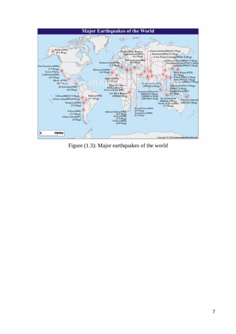
1.4 Fault Types A fault, shown in Figure (1.4), is a large fracture in rocks, across which the rocks have
moved. Faults can be microscopic or hundreds-to-thousands of kilometers long and
tens of kilometers deep. The width of the fault is usually much smaller, on the order of
a few millimeters to meters.
Normal Fault (extensional):
• The hanging wall block moves down relative to the footwall block.
• The fault plane makes 45 degree or larger angles with the surface.
• These faults are associated with crustal tension.
Figure (1.4): Fault types
Reverse Fault (Compressional)
• The hanging wall block moves up relative to the footwall block.
• The fault plane usually makes 45 degree or smaller angles with the surface.
• The faults are associated with crustal compression.
Strike-Slip Fault (Transformal)
• The two blocks move either to the left or to the right relative to one another.
• These faults are associated with crustal shear.
9
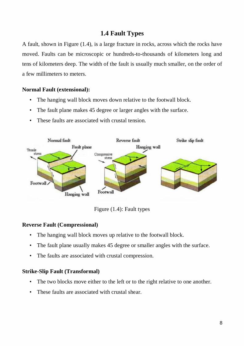
1.5 Earthquakes An earthquake is a sudden movement of the ground that releases built-up energy in
rocks and generates seismic waves. The elastic waves radiate outward from the source
and vibrate the ground. The point where a rupture starts is termed the focus or
hypocenter and may be many kilometers deep within the earth. The point on the
surface directly above the focus is called the earthquake epicenter, shown in Figure
(1.5).
Figure (1.5): Earthquake fracture
Earthquakes can occur anywhere between the Earth's surface and about 700 kilometers
below the surface. For scientific purposes, this earthquake depth range of 0-700 km is
divided into three zones: shallow, intermediate, and deep .
Shallow earthquakes are between 0 and 70 km deep; intermediate earthquakes, 70 -
300 km deep; and deep earthquakes, 300 - 700 km deep. In general, the term "deep-
focus earthquakes" is applied to earthquakes deeper than 70 km.
The Elastic Rebound Theory:
It states that as tectonic plates move relative to each other, elastic strain energy builds
up along their edges in the rocks along fault planes. Since fault planes are not usually
very smooth, great amounts of energy can be stored as movement is restricted due to
interlock along the fault. When the shearing stresses induced in the rocks on the fault
planes exceed the shear strength of the rock, rupture occurs.
10
1.6 Seismic Waves Seismic waves are the vibrations from earthquakes that travel through the earth. The
amplitude of a seismic wave is the amount the ground moves as the wave passes by.
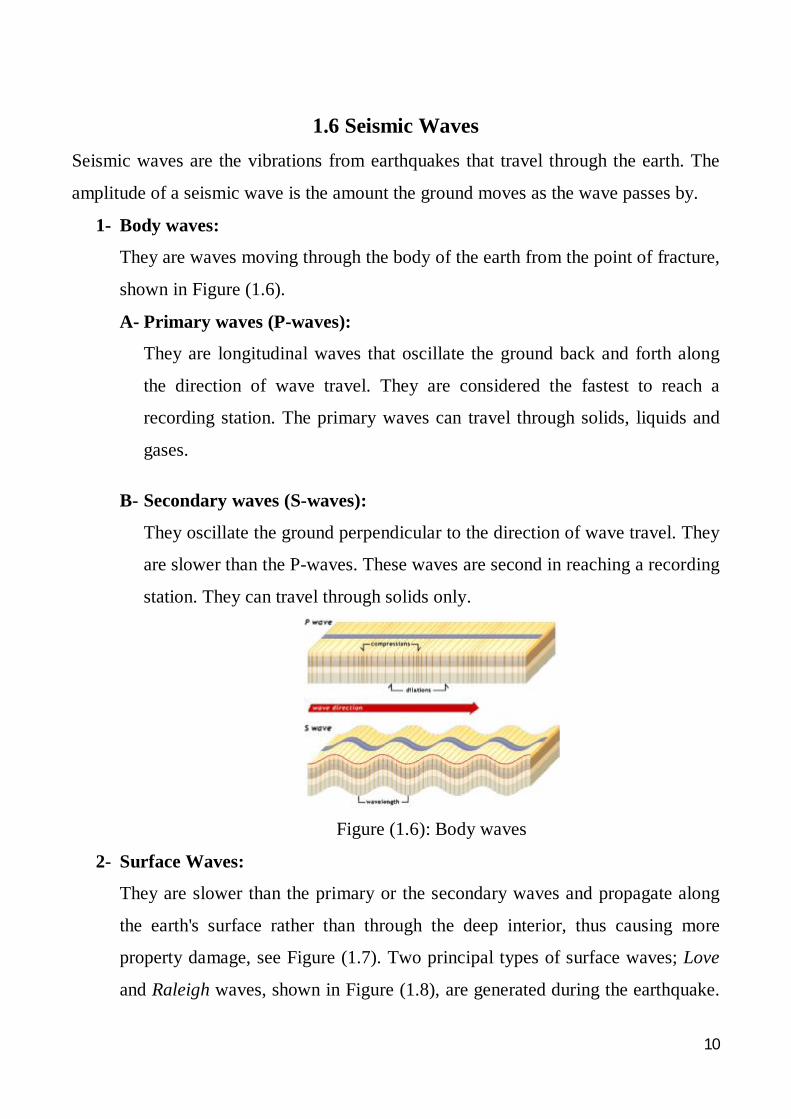
1- Body waves:
They are waves moving through the body of the earth from the point of fracture,
shown in Figure (1.6).
A- Primary waves (P-waves):
They are longitudinal waves that oscillate the ground back and forth along
the direction of wave travel. They are considered the fastest to reach a
recording station. The primary waves can travel through solids, liquids and
gases.
B- Secondary waves (S-waves):
They oscillate the ground perpendicular to the direction of wave travel. They
are slower than the P-waves. These waves are second in reaching a recording
station. They can travel through solids only.
Figure (1.6): Body waves
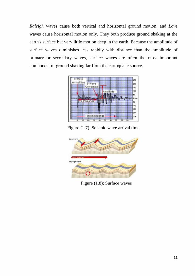
2- Surface Waves:
They are slower than the primary or the secondary waves and propagate along
the earth's surface rather than through the deep interior, thus causing more
property damage, see Figure (1.7). Two principal types of surface waves; Love
and Raleigh waves, shown in Figure (1.8), are generated during the earthquake.
11
Raleigh waves cause both vertical and horizontal ground motion, and Love
waves cause horizontal motion only. They both produce ground shaking at the
earth's surface but very little motion deep in the earth. Because the amplitude of
surface waves diminishes less rapidly with distance than the amplitude of
primary or secondary waves, surface waves are often the most important
component of ground shaking far from the earthquake source.
Figure (1.7): Seismic wave arrival time
Figure (1.8): Surface waves
12
1.7 Measurement of Ground Motion
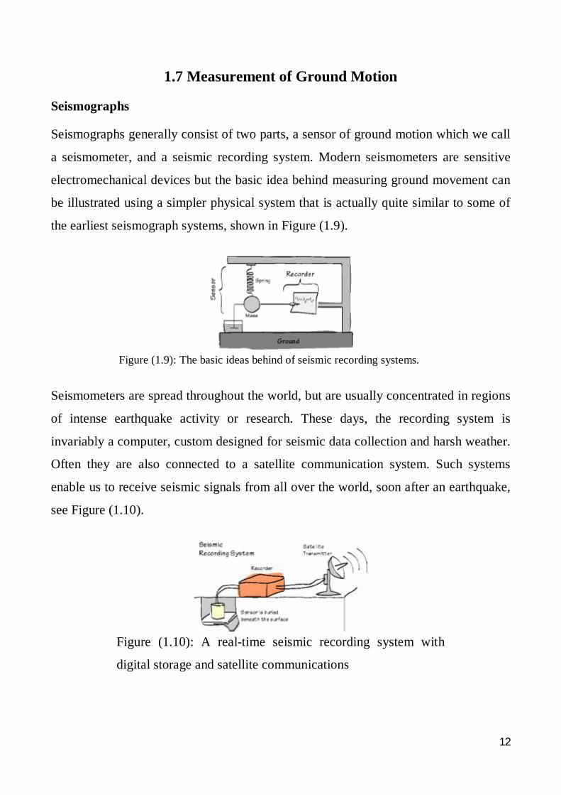
Seismographs
Seismographs generally consist of two parts, a sensor of ground motion which we call
a seismometer, and a seismic recording system. Modern seismometers are sensitive
electromechanical devices but the basic idea behind measuring ground movement can
be illustrated using a simpler physical system that is actually quite similar to some of
the earliest seismograph systems, shown in Figure (1.9).
Figure (1.9): The basic ideas behind of seismic recording systems.
Seismometers are spread throughout the world, but are usually concentrated in regions
of intense earthquake activity or research. These days, the recording system is
invariably a computer, custom designed for seismic data collection and harsh weather.
Often they are also connected to a satellite communication system. Such systems
enable us to receive seismic signals from all over the world, soon after an earthquake,
see Figure (1.10).
Figure (1.10): A real-time seismic recording system with
digital storage and satellite communications
13
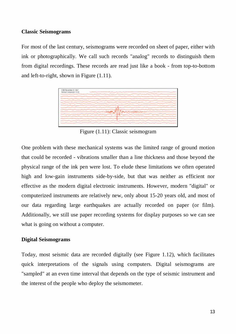
Classic Seismograms
For most of the last century, seismograms were recorded on sheet of paper, either with
ink or photographically. We call such records "analog" records to distinguish them
from digital recordings. These records are read just like a book - from top-to-bottom
and left-to-right, shown in Figure (1.11).
Figure (1.11): Classic seismogram
One problem with these mechanical systems was the limited range of ground motion
that could be recorded - vibrations smaller than a line thickness and those beyond the
physical range of the ink pen were lost. To elude these limitations we often operated
high and low-gain instruments side-by-side, but that was neither as efficient nor
effective as the modern digital electronic instruments. However, modern "digital" or
computerized instruments are relatively new, only about 15-20 years old, and most of
our data regarding large earthquakes are actually recorded on paper (or film).
Additionally, we still use paper recording systems for display purposes so we can see
what is going on without a computer.
Digital Seismograms
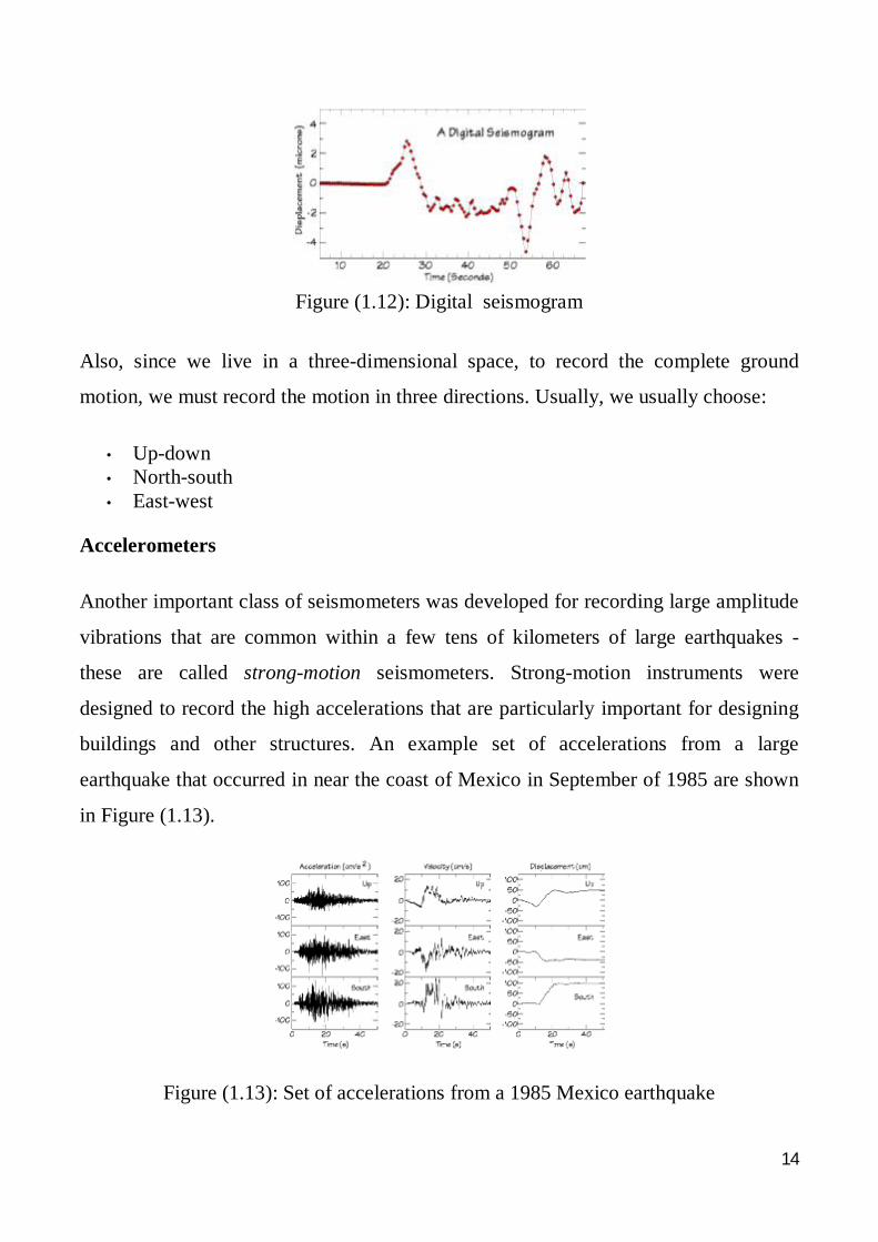
Today, most seismic data are recorded digitally (see Figure 1.12), which facilitates
quick interpretations of the signals using computers. Digital seismograms are
"sampled" at an even time interval that depends on the type of seismic instrument and
the interest of the people who deploy the seismometer.
14
Figure (1.12): Digital seismogram
Also, since we live in a three-dimensional space, to record the complete ground
motion, we must record the motion in three directions. Usually, we usually choose:
• Up-down • North-south • East-west
Accelerometers
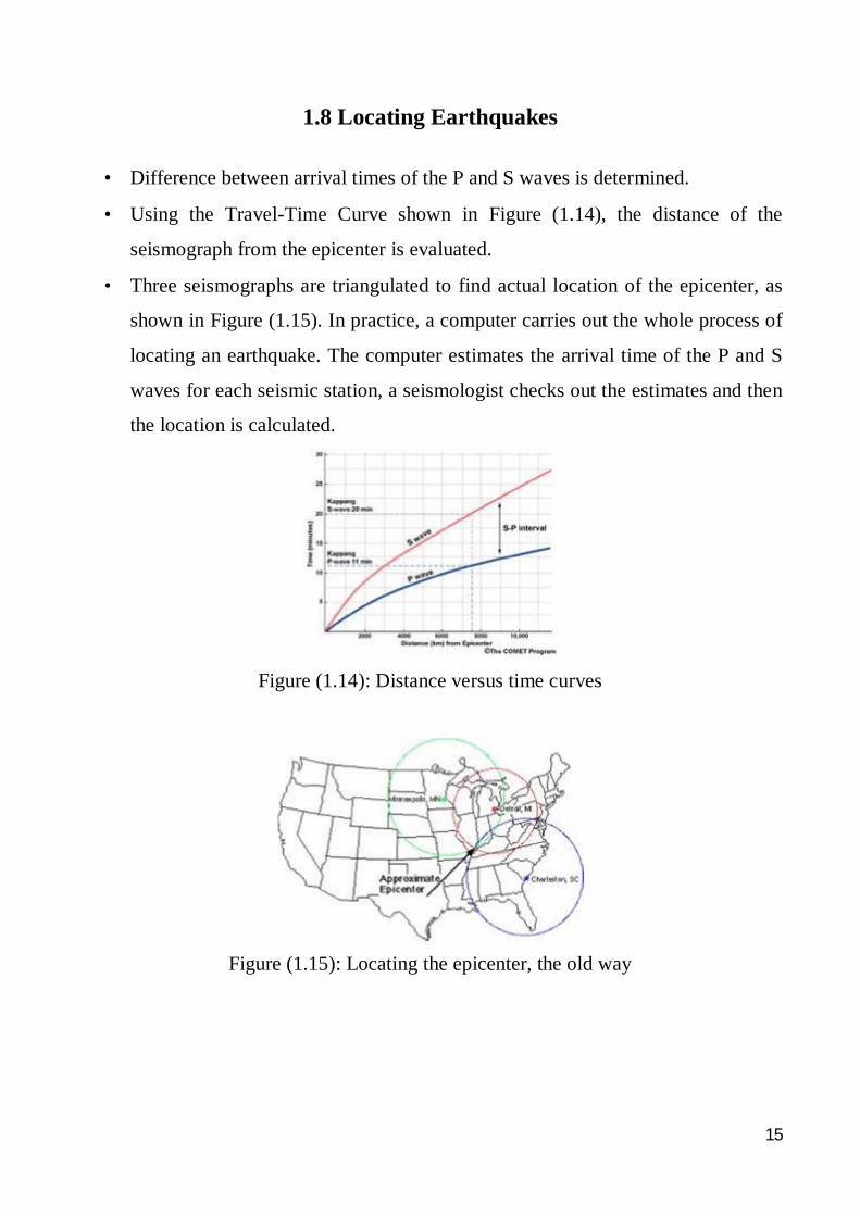
Another important class of seismometers was developed for recording large amplitude
vibrations that are common within a few tens of kilometers of large earthquakes -
these are called strong-motion seismometers. Strong-motion instruments were
designed to record the high accelerations that are particularly important for designing
buildings and other structures. An example set of accelerations from a large
earthquake that occurred in near the coast of Mexico in September of 1985 are shown
in Figure (1.13).
Figure (1.13): Set of accelerations from a 1985 Mexico earthquake
15
1.8 Locating Earthquakes
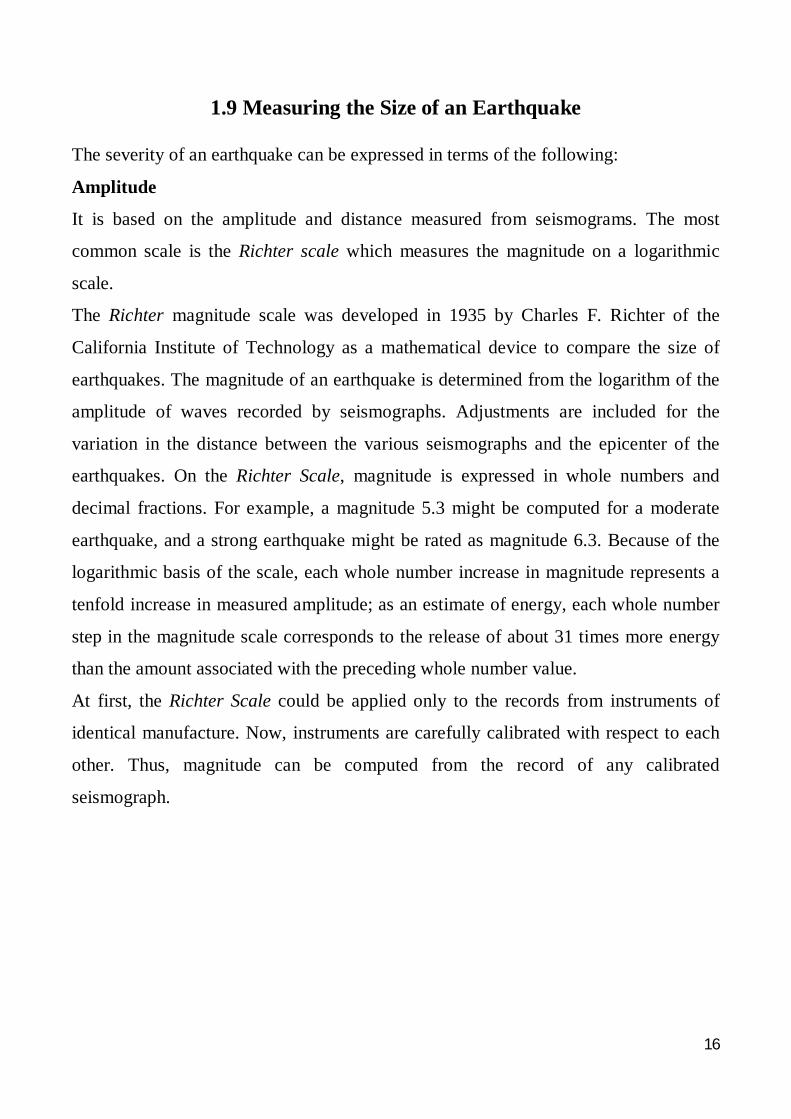
• Difference between arrival times of the P and S waves is determined.
• Using the Travel-Time Curve shown in Figure (1.14), the distance of the
seismograph from the epicenter is evaluated.
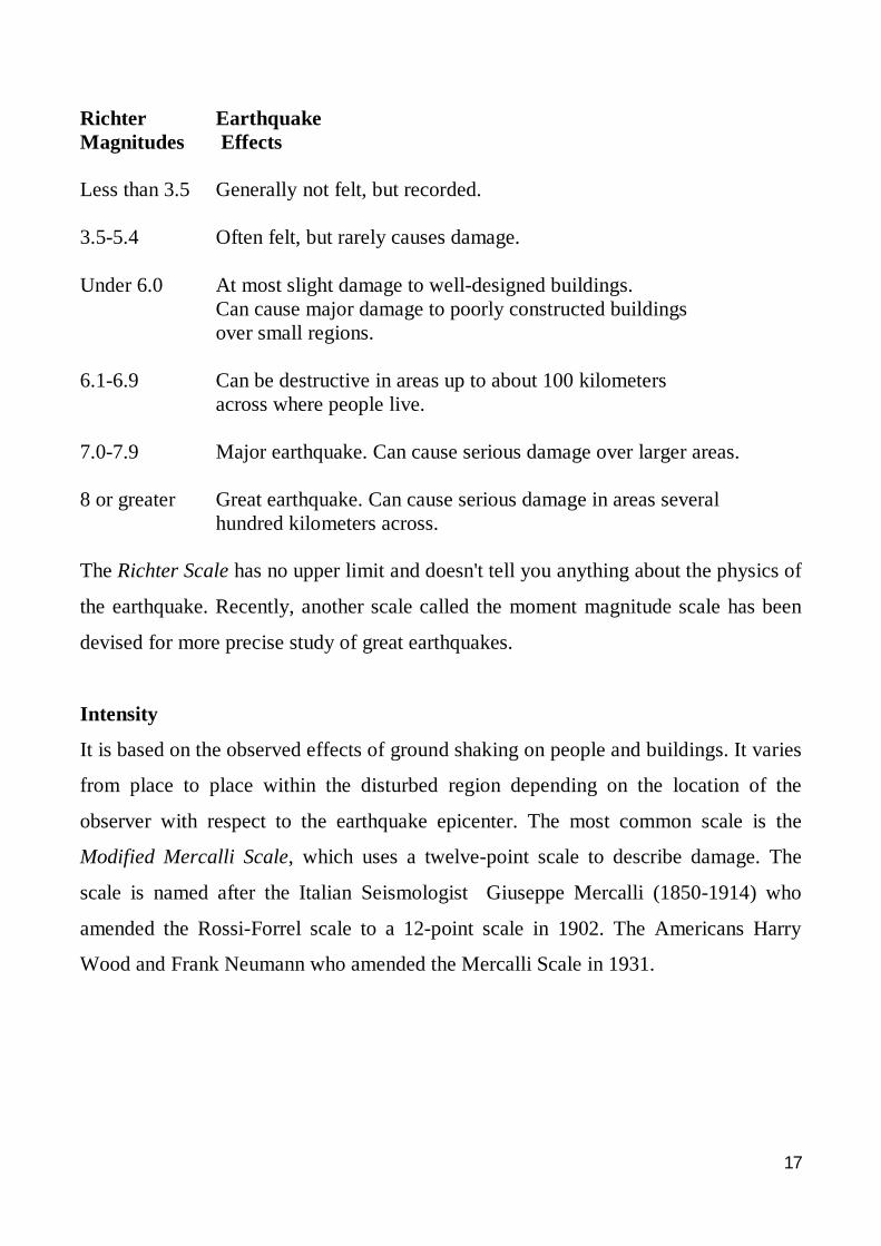
• Three seismographs are triangulated to find actual location of the epicenter, as
shown in Figure (1.15). In practice, a computer carries out the whole process of
locating an earthquake. The computer estimates the arrival time of the P and S
waves for each seismic station, a seismologist checks out the estimates and then
the location is calculated.
Figure (1.14): Distance versus time curves
Figure (1.15): Locating the epicenter, the old way
16
1.9 Measuring the Size of an Earthquake
The severity of an earthquake can be expressed in terms of the following:
Amplitude
It is based on the amplitude and distance measured from seismograms. The most
common scale is the Richter scale which measures the magnitude on a logarithmic
scale.
The Richter magnitude scale was developed in 1935 by Charles F. Richter of the
California Institute of Technology as a mathematical device to compare the size of
earthquakes. The magnitude of an earthquake is determined from the logarithm of the
amplitude of waves recorded by seismographs. Adjustments are included for the
variation in the distance between the various seismographs and the epicenter of the
earthquakes. On the Richter Scale, magnitude is expressed in whole numbers and
decimal fractions. For example, a magnitude 5.3 might be computed for a moderate
earthquake, and a strong earthquake might be rated as magnitude 6.3. Because of the
logarithmic basis of the scale, each whole number increase in magnitude represents a
tenfold increase in measured amplitude; as an estimate of energy, each whole number
step in the magnitude scale corresponds to the release of about 31 times more energy
than the amount associated with the preceding whole number value.
At first, the Richter Scale could be applied only to the records from instruments of
identical manufacture. Now, instruments are carefully calibrated with respect to each
other. Thus, magnitude can be computed from the record of any calibrated
seismograph.
17
Richter Earthquake Magnitudes Effects Less than 3.5 Generally not felt, but recorded. 3.5-5.4 Often felt, but rarely causes damage. Under 6.0 At most slight damage to well-designed buildings. Can cause major damage to poorly constructed buildings over small regions. 6.1-6.9 Can be destructive in areas up to about 100 kilometers across where people live. 7.0-7.9 Major earthquake. Can cause serious damage over larger areas. 8 or greater Great earthquake. Can cause serious damage in areas several hundred kilometers across. The Richter Scale has no upper limit and doesn't tell you anything about the physics of
the earthquake. Recently, another scale called the moment magnitude scale has been
devised for more precise study of great earthquakes.
Intensity
It is based on the observed effects of ground shaking on people and buildings. It varies
from place to place within the disturbed region depending on the location of the
observer with respect to the earthquake epicenter. The most common scale is the
Modified Mercalli Scale, which uses a twelve-point scale to describe damage. The
scale is named after the Italian Seismologist Giuseppe Mercalli (1850-1914) who
amended the Rossi-Forrel scale to a 12-point scale in 1902. The Americans Harry
Wood and Frank Neumann who amended the Mercalli Scale in 1931.
18
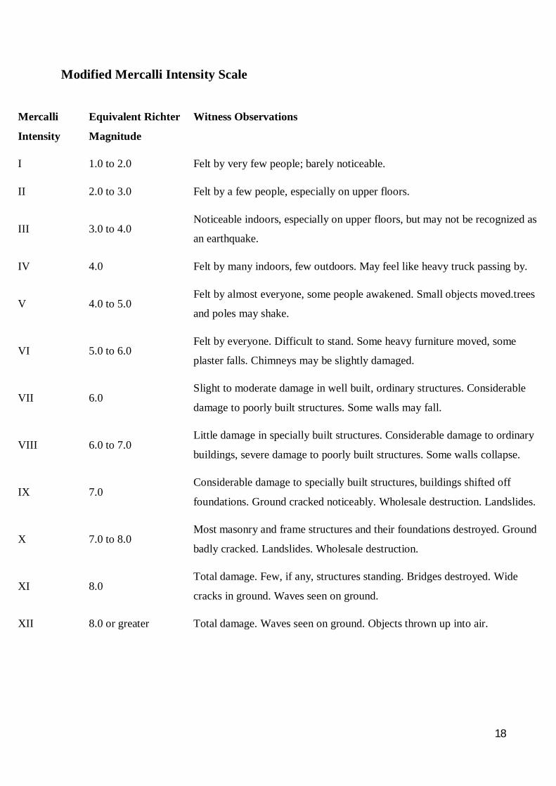
Modified Mercalli Intensity Scale
Mercalli
Intensity
Equivalent Richter
Magnitude
Witness Observations
I 1.0 to 2.0 Felt by very few people; barely noticeable.
II 2.0 to 3.0 Felt by a few people, especially on upper floors.
III 3.0 to 4.0 Noticeable indoors, especially on upper floors, but may not be recognized as
an earthquake.
IV 4.0 Felt by many indoors, few outdoors. May feel like heavy truck passing by.
V 4.0 to 5.0 Felt by almost everyone, some people awakened. Small objects moved.trees
and poles may shake.
VI 5.0 to 6.0 Felt by everyone. Difficult to stand. Some heavy furniture moved, some
plaster falls. Chimneys may be slightly damaged.
VII 6.0 Slight to moderate damage in well built, ordinary structures. Considerable
damage to poorly built structures. Some walls may fall.
VIII 6.0 to 7.0 Little damage in specially built structures. Considerable damage to ordinary
buildings, severe damage to poorly built structures. Some walls collapse.
IX 7.0 Considerable damage to specially built structures, buildings shifted off
foundations. Ground cracked noticeably. Wholesale destruction. Landslides.
X 7.0 to 8.0 Most masonry and frame structures and their foundations destroyed. Ground
badly cracked. Landslides. Wholesale destruction.
XI 8.0 Total damage. Few, if any, structures standing. Bridges destroyed. Wide
cracks in ground. Waves seen on ground.
XII 8.0 or greater Total damage. Waves seen on ground. Objects thrown up into air.
19
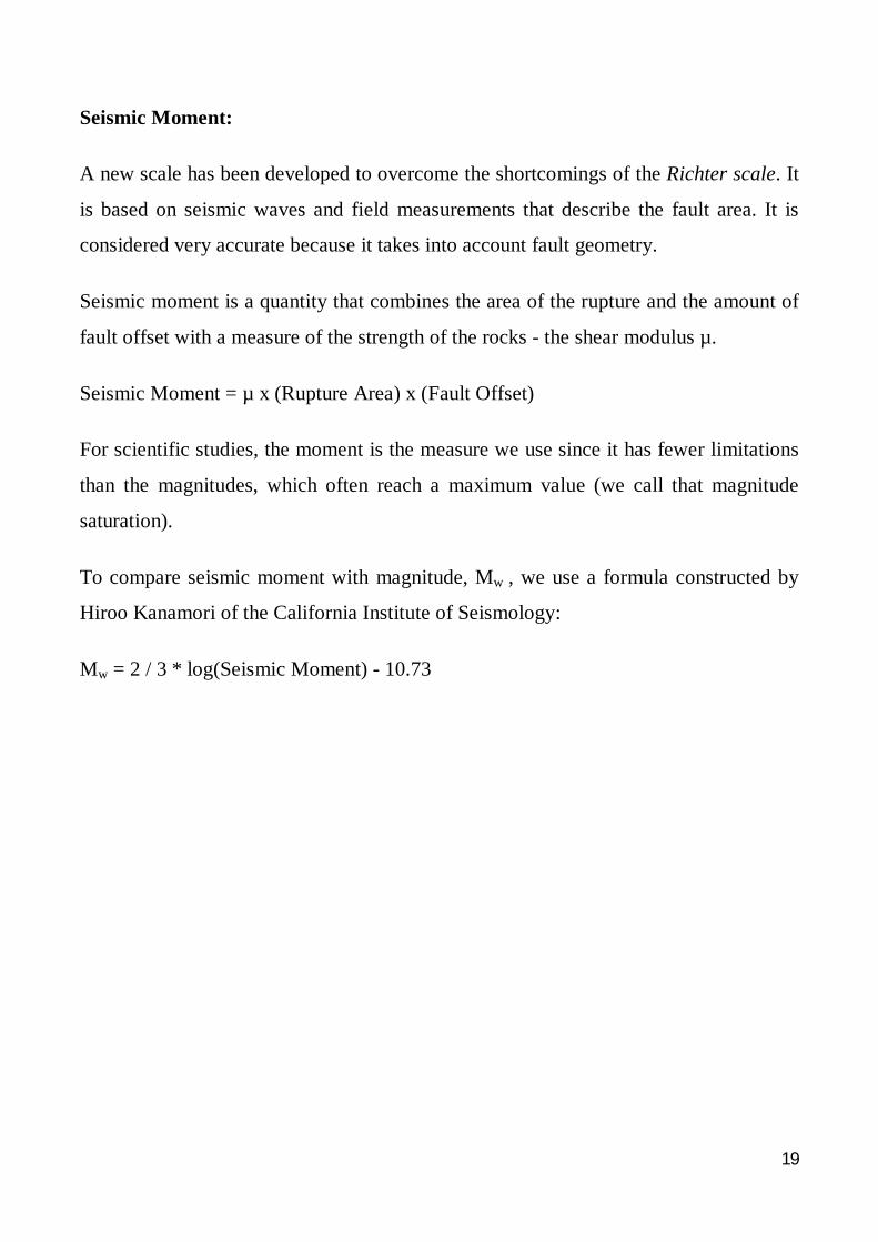
Seismic Moment:
A new scale has been developed to overcome the shortcomings of the Richter scale. It
is based on seismic waves and field measurements that describe the fault area. It is
considered very accurate because it takes into account fault geometry.
Seismic moment is a quantity that combines the area of the rupture and the amount of
fault offset with a measure of the strength of the rocks - the shear modulus µ.
Seismic Moment = µ x (Rupture Area) x (Fault Offset)
For scientific studies, the moment is the measure we use since it has fewer limitations
than the magnitudes, which often reach a maximum value (we call that magnitude
saturation).
To compare seismic moment with magnitude, Mw , we use a formula constructed by
Hiroo Kanamori of the California Institute of Seismology:
Mw = 2 / 3 * log(Seismic Moment) - 10.73
20
Part (2)
Effects of Earthquakes on Structures and Planning Considerations
• The Nature of Earthquake Hazard
• Architectural and Structural Considerations
• The Effects of Earthquakes on Buildings
• General Goals in Seismic-Resistant Design
21
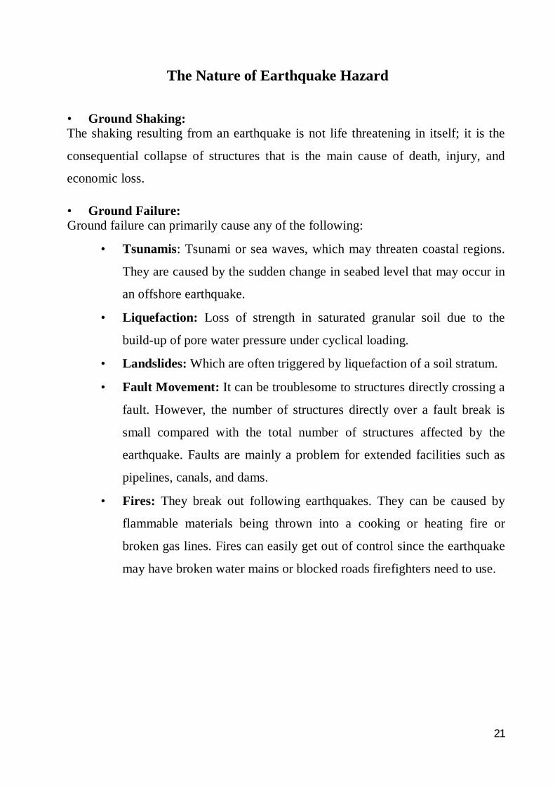
The Nature of Earthquake Hazard
• Ground Shaking: The shaking resulting from an earthquake is not life threatening in itself; it is the
consequential collapse of structures that is the main cause of death, injury, and
economic loss.
• Ground Failure: Ground failure can primarily cause any of the following:
• Tsunamis: Tsunami or sea waves, which may threaten coastal regions.
They are caused by the sudden change in seabed level that may occur in
an offshore earthquake.
• Liquefaction: Loss of strength in saturated granular soil due to the
build-up of pore water pressure under cyclical loading.
• Landslides: Which are often triggered by liquefaction of a soil stratum.
• Fault Movement: It can be troublesome to structures directly crossing a
fault. However, the number of structures directly over a fault break is
small compared with the total number of structures affected by the
earthquake. Faults are mainly a problem for extended facilities such as
pipelines, canals, and dams.
• Fires: They break out following earthquakes. They can be caused by
flammable materials being thrown into a cooking or heating fire or
broken gas lines. Fires can easily get out of control since the earthquake
may have broken water mains or blocked roads firefighters need to use.
22
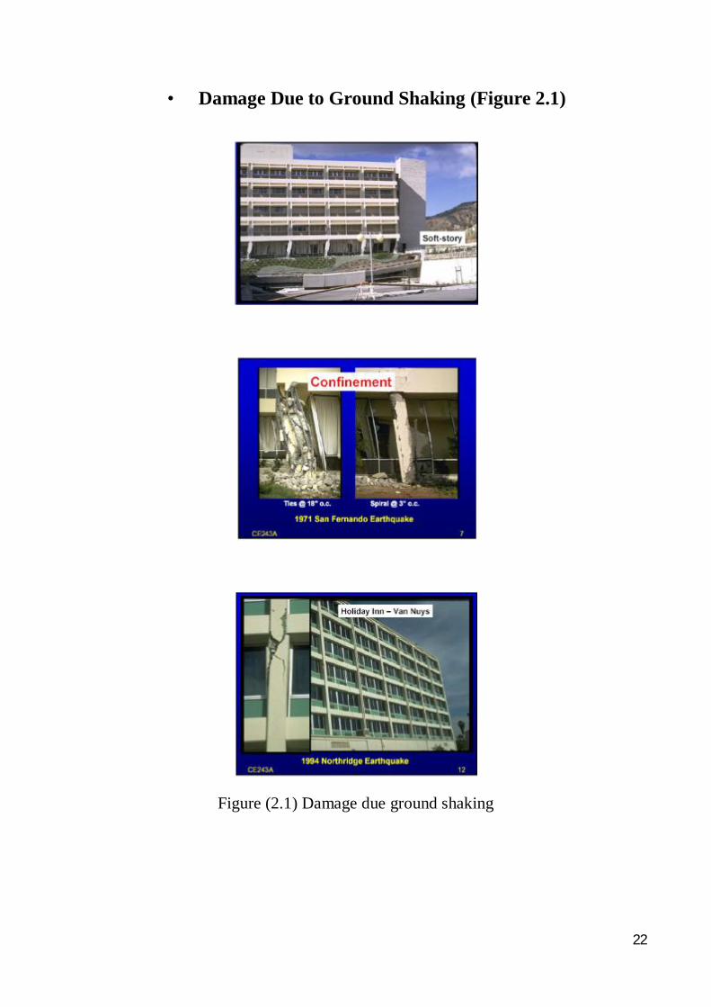
• Damage Due to Ground Shaking (Figure 2.1)
Figure (2.1) Damage due ground shaking
23
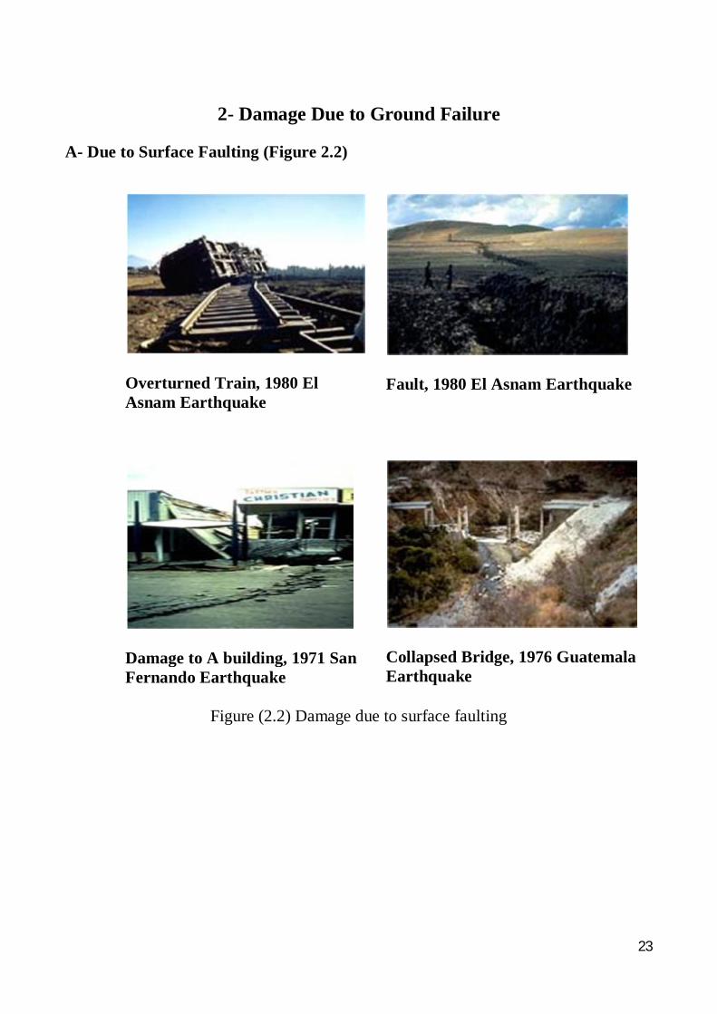
2- Damage Due to Ground Failure
A- Due to Surface Faulting (Figure 2.2)
Fault, 1980 El Asnam Earthquake
Overturned Train, 1980 El Asnam Earthquake
Collapsed Bridge, 1976 Guatemala Earthquake
Damage to A building, 1971 San Fernando Earthquake
Figure (2.2) Damage due to surface faulting
24
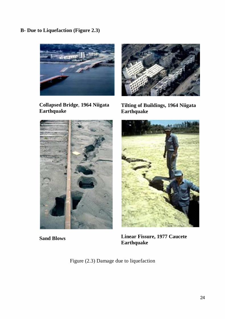
B- Due to Liquefaction (Figure 2.3)
Tilting of Buildings, 1964 Niigata Earthquake
Collapsed Bridge, 1964 Niigata Earthquake
Linear Fissure, 1977 Caucete Earthquake
Sand Blows
Figure (2.3) Damage due to liquefaction
25
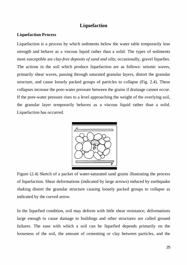
Liquefaction Liquefaction Process Liquefaction is a process by which sediments below the water table temporarily lose
strength and behave as a viscous liquid rather than a solid. The types of sediments
most susceptible are clay-free deposits of sand and silts; occasionally, gravel liquefies.
The actions in the soil which produce liquefaction are as follows: seismic waves,
primarily shear waves, passing through saturated granular layers, distort the granular
structure, and cause loosely packed groups of particles to collapse (Fig. 2.4). These
collapses increase the pore-water pressure between the grains if drainage cannot occur.
If the pore-water pressure rises to a level approaching the weight of the overlying soil,
the granular layer temporarily behaves as a viscous liquid rather than a solid.
Liquefaction has occurred.
Figure (2.4) Sketch of a packet of water-saturated sand grains illustrating the process
of liquefaction. Shear deformations (indicated by large arrows) induced by earthquake
shaking distort the granular structure causing loosely packed groups to collapse as
indicated by the curved arrow.
In the liquefied condition, soil may deform with little shear resistance; deformations
large enough to cause damage to buildings and other structures are called ground
failures. The ease with which a soil can be liquefied depends primarily on the
looseness of the soil, the amount of cementing or clay between particles, and the
26
amount of drainage restriction. The amount of soil deformation following liquefaction
depends on the looseness of the material, the depth, thickness, and areal extent of the
liquefied layer, the ground slope, and the distribution of loads applied by buildings and
other structures.
Liquefaction does not occur at random, but is restricted to certain geologic and
hydrologic environments, primarily recently deposited sands and silts in areas with
high ground water levels. Generally, the younger and looser the sediment, and the
higher the water table, the more susceptible the soil is to liquefaction. Liquefaction has
been most abundant in areas where ground water lies within 10 m of the ground
surface; few instances of liquefaction have occurred in areas with ground water deeper
than 20 m. Dense soils, including well-compacted fills, have low susceptibility to
liquefaction. Effect of Liquefaction on the Built Environment
The liquefaction phenomenon by itself may not be particularly damaging or
hazardous. Only when liquefaction is accompanied by some form of ground
displacement or ground failure is it destructive to the built environment. For
engineering purposes, it is not the occurrence of liquefaction that is of prime
importance, but its severity or its capability to cause damage. Adverse effects of
liquefaction can take many forms. These include: flow failures; lateral spreads; ground
oscillation; and increased lateral pressure on retaining walls.
Flow Failures Flow failures are the most catastrophic ground failures caused by liquefaction. These
failures commonly displace large masses of soil laterally tens of meters and in a few
instances; large masses of soil have traveled tens of kilometers down long slopes at
velocities ranging up to tens of kilometers per hour. Flows may be comprised of
completely liquefied soil or blocks of intact material riding on a layer of liquefied soil.
Flows develop in loose saturated sands or silts on relatively steep slopes, usually
greater than 3 degrees.
27
Lateral Spreads Lateral spreads involve lateral displacement of large, surficial blocks of soil as a result
of liquefaction of a subsurface layer. Displacement occurs in response to the
combination of gravitational forces and inertial forces generated by an earthquake.
Lateral spreads generally develop on gentle slopes (most commonly less than 3
degrees) and move toward a free face such as an incised river channel. Horizontal
displacements commonly range up to several meters. The displaced ground usually
breaks up internally, causing fissures and scarps to form on the failure surface. Lateral
spreads commonly disrupt foundations of buildings built on or across the failure, sever
pipelines and other utilities in the failure mass, and compress or buckle engineering
structures, such as bridges, founded on the toe of the failure.
Damage caused by lateral spreads is severely disruptive and often pervasive. For
example, during the 1964 Alaska earthquake, more than 200 bridges were damaged or
destroyed by spreading of floodplain deposits toward river channels. The spreading
compressed the superstructures, buckled decks, thrust stringers over abutments, and
shifted and tilted abutments and piers. Lateral spreads are particularly destructive to
pipelines. For example, every major pipeline break in the city of San Francisco during
the 1906 earthquake occurred in areas of ground failure. These pipeline breaks
severely hampered efforts to fight the fire that ignited during the earthquake; that fire
caused about 85% of the total damage to San Francisco. Thus, rather inconspicuous
ground-failure displacements of less than 2 m were in large part responsible for the
devastation that occurred in San Francisco.
Ground Oscillation Where the ground is flat or the slope is too gentle to allow lateral displacement,
liquefaction at depth may decouple overlying soil layers from the underlying ground,
allowing the upper soil to oscillate back and forth and up and down in the form of
28
ground waves. These oscillations are usually accompanied by opening and closing of
fissures and fracture of rigid structures such as pavements and pipelines. The
manifestations of ground oscillation were apparent in San Francisco’s Marina District
due to the 1989 Loma Prieta earthquake; sidewalks and driveways buckled and
extensive pipeline breakage also occurred.
Loss of Bearing Strength When the soil supporting a building or other structure liquefies and loses strength,
large deformations can occur within the soil which may allow the structure to settle
and tip. Conversely, buried tanks and piles may rise buoyantly through the liquefied
soil. For example, many buildings settled and tipped during the 1964 Niigata, Japan,
earthquake. The most spectacular bearing failures during that event were in the
Kawangishicho apartment complex where several four-story buildings tipped as much
as 60 degrees. Apparently, liquefaction first developed in a sand layer several meters
below ground surface and then propagated upward through overlying sand layers. The
rising wave of liquefaction weakened the soil supporting the buildings and allowed the
structures to slowly settle and tip.
Settlement In many cases, the weight of a structure will not be great enough to cause the large
settlements associated with soil bearing capacity failures described above. However,
smaller settlements may occur as soil pore-water pressures dissipate and the soil
consolidates after the earthquake. These settlements may be damaging, although they
would tend to be much less so than the large movements accompanying flow failures,
lateral spreading, and bearing capacity failures. The eruption of sand boils (fountains
of water and sediment emanating from the pressurized, liquefied sand) is a common
manifestation of liquefaction that can also lead to localized differential settlements.
29
Increased Lateral Pressure on Retaining Walls If the soil behind a retaining wall liquefies, the lateral pressures on the wall may
greatly increase. As a result, retaining walls may be laterally displaced, tilt, or
structurally fail, as has been observed for waterfront walls retaining loose saturated
sand in a number of earthquakes.
Can Liquefaction Be Predicted?
Although it is possible to identify areas that have the potential for liquefaction, its
occurrence cannot be predicted any more accurately than a particular earthquake can
be (with a time, place, and degree of reliability assigned to it). Once these areas have
been defined in general terms, it is possible to conduct site investigations that provide
very detailed information regarding a site’s potential for liquefaction. Mapping of the
liquefaction potential on a regional scale has greatly furthered our knowledge
regarding this hazard. These maps now exist for many regions of the United States,
Japan and several other areas of the world.
30
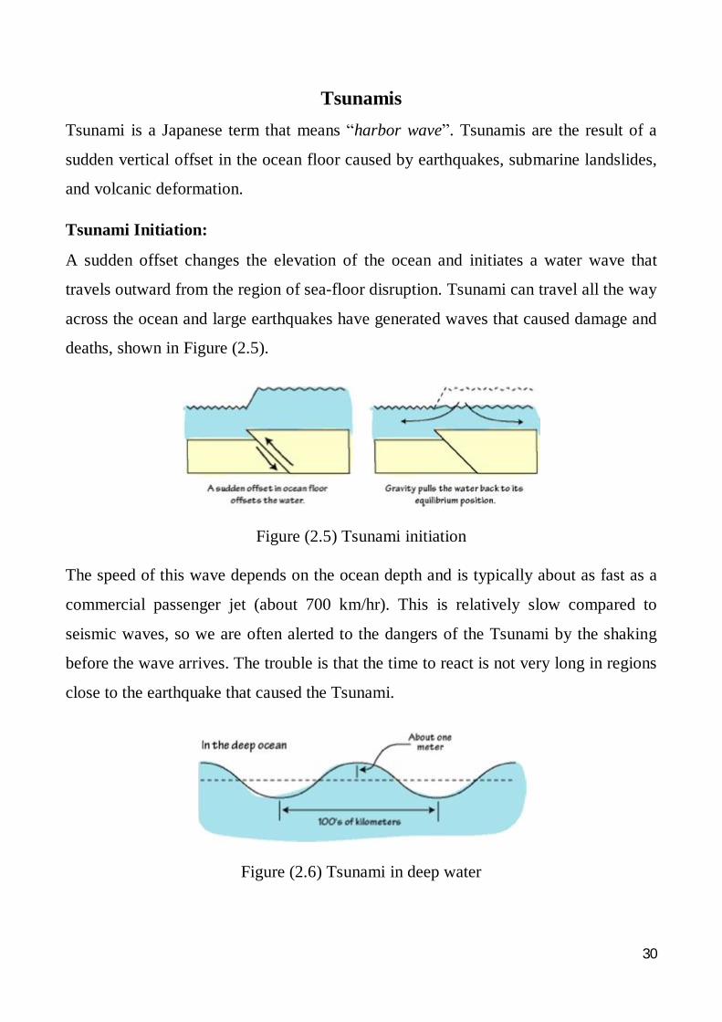
Tsunamis
Tsunami is a Japanese term that means “harbor wave”. Tsunamis are the result of a
sudden vertical offset in the ocean floor caused by earthquakes, submarine landslides,
and volcanic deformation.
Tsunami Initiation:
A sudden offset changes the elevation of the ocean and initiates a water wave that
travels outward from the region of sea-floor disruption. Tsunami can travel all the way
across the ocean and large earthquakes have generated waves that caused damage and
deaths, shown in Figure (2.5).
Figure (2.5) Tsunami initiation
The speed of this wave depends on the ocean depth and is typically about as fast as a
commercial passenger jet (about 700 km/hr). This is relatively slow compared to
seismic waves, so we are often alerted to the dangers of the Tsunami by the shaking
before the wave arrives. The trouble is that the time to react is not very long in regions
close to the earthquake that caused the Tsunami.
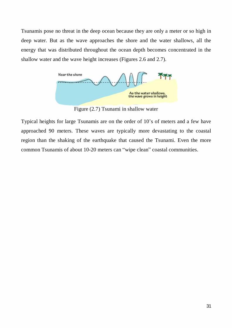
Figure (2.6) Tsunami in deep water
31
Tsunamis pose no threat in the deep ocean because they are only a meter or so high in
deep water. But as the wave approaches the shore and the water shallows, all the
energy that was distributed throughout the ocean depth becomes concentrated in the
shallow water and the wave height increases (Figures 2.6 and 2.7).
Figure (2.7) Tsunami in shallow water
Typical heights for large Tsunamis are on the order of 10’s of meters and a few have
approached 90 meters. These waves are typically more devastating to the coastal
region than the shaking of the earthquake that caused the Tsunami. Even the more
common Tsunamis of about 10-20 meters can “wipe clean” coastal communities.