Embed Size (px)
Citation preview
OL-26591-01
C H A P T E R 1
RAID OverviewThis chapter describes RAID (Redundant Array of Independent Disks), RAID functions and benefits, RAID components, RAID levels, and configuration strategies.
This chapter contains the following sections:
• Information About RAID, page 1-1
• RAID Levels, page 1-8
• Generic Drive Replacement Procedure, page 1-18
• Platform-Specific RAID and Drive Procedures, page 1-19
Information About RAID RAID is an array, or group, of multiple independent physical drives that provide high performance and fault tolerance. A RAID drive group improves input/output (I/O) performance and reliability. The RAID drive group appears to the host computer as a single storage unit or as multiple virtual units. I/O is expedited because several drives can be accessed simultaneously.
RAID drive groups improve data storage reliability and fault tolerance compared to single-drive storage systems. Data loss resulting from a drive failure can be prevented by reconstructing missing data from the remaining drives. RAID improves I/O performance and increases storage subsystem reliability.
RAID levels describe a system for ensuring the availability and redundancy of data stored on large disk subsystems. See RAID Levels, page 1-8 for detailed information about RAID levels. The RAID drive-group components and RAID levels are described in the following sections.
Drive Group A drive group is a group of physical drives. These drives are managed in partitions known as virtual drives.
Virtual DriveA virtual drive is a partition in a drive group that is made up of contiguous data segments on the drives. A virtual drive can consist of an entire drive group, more than one entire drive group, a part of a drive group, parts of more than one drive group, or a combination of any two of these conditions.
1-1Cisco UCS Servers RAID Guide

Chapter 1 RAID Overview Information About RAID
Disk StripingDisk striping (used in RAID level 0) allows you to write data across multiple drives instead of only one drive. Disk striping involves partitioning each drive storage space into stripes that can vary in size from 8 KB to 1024 KB. These stripes are interleaved in a repeated sequential manner. The combined storage space is composed of stripes from each drive. We recommend that you keep stripe sizes the same across RAID drive groups.
For example, in a four-disk system using only disk striping, segment 1 is written to disk 1, segment 2 is written to disk 2, and so on (see Figure 1-1). Disk striping enhances performance because multiple drives are accessed simultaneously, but disk striping does not provide data redundancy
Figure 1-1 Example of Disk Striping (RAID 0)
Stripe width is the number of drives involved in a drive group where striping is implemented. For example, a four-disk drive group with disk striping has a stripe width of four.
The stripe size is the length of the interleaved data segments that the RAID controller writes across multiple drives, not including parity drives. For example, consider a stripe that contains 64 KB of disk space and has 16 KB of data residing on each disk in the stripe. In this case, the stripe size is 64 KB and the strip size is 16 KB.
The strip size is the portion of a stripe that resides on a single drive.
Disk Mirroring (RAID 1 and RAID 10)With disk mirroring (used in RAID 1 and RAID 10), data written to one drive is simultaneously written to another drive. The primary advantage of disk mirroring is that it provides 100 percent data redundancy. Because the contents of the disk are completely written to a second disk, data is not lost if one disk fails. In addition, both drives contain the same data at all times, so either disk can act as the operational disk. If one disk fails, the contents of the other disk can be used to run the system and reconstruct the failed disk.
Disk mirroring provides 100 percent redundancy but is expensive because each drive in the system must be duplicated (see Figure 1-2).
Segment 1Segment 5Segment 9
Segment 2Segment 6Segment 10
Segment 3Segment 7Segment 11
Segment 4Segment 8Segment 12 33
2084
1-2Cisco UCS Servers RAID Guide
OL-26591-01

Chapter 1 RAID Overview Information About RAID
Figure 1-2 Example of Disk Mirroring (RAID 1)
ParityParity generates a set of redundancy data from two or more parent data sets. The redundancy data can be used to reconstruct one of the parent data sets in the event of a drive failure. Parity data does not fully duplicate the parent data sets, but parity generation can slow the write process. In RAID, this method is applied to entire drives or stripes across all of the drives in a drive group. There are two types of parity:
• Dedicated parity—The parity data on two or more drives is stored on an additional disk.
• Distributed parity—The parity data is distributed across more than one drive in the system.
RAID 5 combines distributed parity with disk striping (see Figure 1-3). If a single drive fails, it can be rebuilt from the parity and the data on the remaining drives. RAID 5 uses parity to provide redundancy for one drive failure without duplicating the contents of entire drives. RAID 6 uses distributed parity and disk striping also but adds a second set of parity data so that it can survive up to two drive failures.
Note Parity is distributed across all drives in the drive group.
Figure 1-3 Example of Distributed Parity (RAID 5)
Disk SpanningDisk spanning allows multiple drives to function like one big drive. Spanning overcomes lack of disk space and simplifies storage management by combining existing resources or adding relatively inexpensive resources. For example, four 20-GB drives can be combined to appear to the operating system as a single 80-GB drive.
Segment 1Segment 2Segment 3
Segment 1 DuplicatedSegment 2 DuplicatedSegment 3 Duplicated
Segment 4 Segment 4 Duplicated 3320
85
Segment 1Segment 7
Segment 2Segment 8
Segment 3Segment 9
Segment 4Segment 10
Segment 5Parity (6–10)
Parity (11–15)
Parity (1–5)Segment 6Segment 12Segment 15 Segment 11Segment 14Segment 13
Segment 19Segment 25
Segment 20Segment 23
Segment 18Segment 21
Segment 16Segment 22
Segment 17Parity (21–25)
Parity (26–30)
Segment 24
Segment 3092 tnemgeS72 tnemgeSSegment 26 Segment 28
Parity (16–20)
3320
86
1-3Cisco UCS Servers RAID Guide
OL-26591-01

Chapter 1 RAID Overview Information About RAID
Spanning alone does not provide reliability or performance enhancements. Spanned virtual drives must have the same stripe size and must be contiguous. In Figure 1-4, RAID 1 drive groups are turned into a RAID 10 drive group.
Note Make sure that the spans are in different backplanes, so that if one span fails, you do not lose the whole drive group.
Figure 1-4 Example of Disk Spanning
Spanning two contiguous RAID 0 virtual drives does not produce a new RAID level or add fault tolerance. It does increase the capacity of the virtual drive and improves performance by doubling the number of physical disks.
Table 1-1 describes how to configure RAID 00, RAID 10, RAID 50, and RAID 60 by spanning. The virtual drives must have the same stripe size and the maximum number of spans is eight. The full drive capacity is used when you span virtual drives; you cannot specify a smaller drive capacity.
Hot SparesA hot spare is an extra, unused drive that is part of the disk subsystem. It is usually in standby mode, ready for service if a drive fails. If a drive used in a RAID virtual drive fails, a hot spare automatically takes its place and the data on the failed drive is rebuilt on the hot spare. Hot spares can be used for RAID levels 1, 5, 6, 10, 50, and 60.
60 GB 60 GB
Can be accessed asone 120-GB drive
60 GB 60 GB
Can be accessed asone 120-GB drive
3320
87
Table 1-1 Spanning for RAID 00, RAID 10, RAID 50, and RAID 60
RAIDLevel Description
00 Configure RAID 00 by spanning two contiguous RAID 0 virtual drives, up to the maximum number of supported devices for the controller.
10 Configure RAID 10 by spanning two contiguous RAID 1 virtual drives, up to the maximum number of supported devices for the controller.
RAID 10 supports a maximum of eight spans. You must use an even number of drives in each RAID virtual drive in the span.
The RAID 1 virtual drives must have the same stripe size.
50 Configure RAID 50 by spanning two contiguous RAID 5 virtual drives.
The RAID 5 virtual drives must have the same stripe size.
60 Configure RAID 60 by spanning two contiguous RAID 6 virtual drives.
The RAID 6 virtual drives must have the same stripe size.
1-4Cisco UCS Servers RAID Guide
OL-26591-01

Chapter 1 RAID Overview Information About RAID
Hot spares permit you to replace failed drives without system shutdown or user intervention. MegaRAID SAS RAID controllers can implement automatic and transparent rebuilds of failed drives using hot spare drives, providing a high degree of fault tolerance and zero downtime.
Note When running RAID 0 and RAID 5 virtual drives on the same set of drives (a sliced configuration), a rebuild to a hot spare cannot occur after a drive failure until the RAID 0 virtual drive is deleted.
The LSI RAID management software allows you to specify drives as hot spares. When a hot spare is needed, the RAID controller assigns the hot spare that has a capacity closest to and at least as great as that of the failed drive to take the place of the failed drive. The failed drive is removed from the virtual drive and marked ready awaiting removal once the rebuild to a hot spare begins. You can make hot spares of the drives that are not in a RAID virtual drive.
You can use the RAID management software to designate the hot spare to have enclosure affinity, which means that if drive failures are present on a split backplane configuration, the hot spare is used first on the backplane side that it resides in.
If the hot spare is designated as having enclosure affinity, it attempts to rebuild any failed drives on the backplane that it resides in before rebuilding any other drives on other backplanes.
Note If a rebuild to a hot spare fails for any reason, the hot spare drive is marked as failed. If the source drive fails, both the source drive and the hot spare drive is marked as failed.
There are two types of hot spares:
• Global hot spare
• Dedicated hot spare
Global Hot Spare
A global hot spare drive can be used to replace any failed drive in a redundant drive group as long as its capacity is equal to or larger than the capacity of the failed drive. A global hot spare defined on any channel should be available to replace a failed drive on both channels.
Dedicated Hot Spare
A dedicated hot spare can be used to replace a failed drive only in a chosen drive group. One or more drives can be designated as a member of a spare drive pool. The most suitable drive from the pool is chosen for failover. A dedicated hot spare is used before one from the global hot spare pool.
Hot spare drives can be located on any RAID channel. Standby hot spares (not being used in RAID drive group) are polled every 60 seconds at a minimum, and their status is made available in the drive group management software. RAID controllers offer the ability to rebuild with a disk that is in a system, but not initially set to be a hot spare.
When using hot spares, observe the following guidelines:
• Hot spares are used only in drive groups with redundancy, which includes RAID levels 1, 5, 6, 10, 50, and 60.
• A hot spare connected to a specific RAID controller can be used to rebuild a drive that is connected to the same controller only.
1-5Cisco UCS Servers RAID Guide
OL-26591-01

Chapter 1 RAID Overview Information About RAID
• You must assign the hot spare to one or more drives through the controller BIOS or use drive group management software to place it in the hot spare pool.
• A hot spare must have free space equal to or greater than the drive it replaces. For example, to replace an 18-GB drive, the hot spare must be 18 GB or larger.
Disk RebuildsWhen a drive in a RAID drive group fails, you can rebuild the drive by recreating the data that was stored on the drive before it failed. The RAID controller recreates the data using the data stored on the other drives in the drive group. Rebuilding can be done only in drive groups with data redundancy, which includes RAID 1, 5, 6, 10, 50, and 60 drive groups.
The RAID controller uses hot spares to rebuild failed drives automatically and transparently, at user-defined rebuild rates. If a hot spare is available, the rebuild can start automatically when a drive fails. If a hot spare is not available, the failed drive must be replaced with a new drive so that the data on the failed drive can be rebuilt.
The failed drive is removed from the virtual drive and marked ready awaiting removal when the rebuild to a hot spare begins. If the system goes down during a rebuild, the RAID controller automatically restarts the rebuild after the system reboots.
Note When the rebuild to a hot spare begins, the failed drive is often removed from the virtual drive before management applications detect the failed drive. When this situation occurs, the events logs show the drive rebuilding to the hot spare without showing the failed drive. The formerly failed drive is marked as ready after a rebuild begins to a hot spare.
Note If a source drive fails during a rebuild to a hot spare, the rebuild fails, and the failed source drive is marked as offline. In addition, the rebuilding hot spare drive is changed back to a hot spare. After a rebuild fails because of a source drive failure, the dedicated hot spare is still dedicated and assigned to the correct drive group, and the global hot spare is still global.
An automatic drive rebuild does not start if you replace a drive during a RAID-level migration. The rebuild must be started manually after the expansion or migration procedure is complete. (RAID-level migration changes a virtual drive from one RAID level to another.)
Hot SwapA hot swap is the manual replacement of a defective drive unit while the computer is still running (performing its normal functions). When a new drive is installed, a rebuild occurs automatically if one of the following happens:
• The newly inserted drive is the same capacity as or larger than the failed drive.
• It is placed in the same drive bay as the failed drive it is replacing.
The RAID controller can be configured to detect the new drives and rebuild the contents of the drive automatically. The backplane and enclosure must support hot swap for the functionality to work.
1-6Cisco UCS Servers RAID Guide
OL-26591-01
Chapter 1 RAID Overview Information About RAID
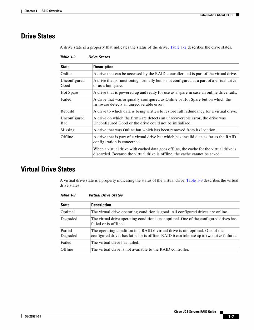
Drive StatesA drive state is a property that indicates the status of the drive. Table 1-2 describes the drive states.
Virtual Drive StatesA virtual drive state is a property indicating the status of the virtual drive. Table 1-3 describes the virtual drive states.
Table 1-2 Drive States
State Description
Online A drive that can be accessed by the RAID controller and is part of the virtual drive.
Unconfigured Good
A drive that is functioning normally but is not configured as a part of a virtual drive or as a hot spare.
Hot Spare A drive that is powered up and ready for use as a spare in case an online drive fails.
Failed A drive that was originally configured as Online or Hot Spare but on which the firmware detects an unrecoverable error.
Rebuild A drive to which data is being written to restore full redundancy for a virtual drive.
Unconfigured Bad
A drive on which the firmware detects an unrecoverable error; the drive was Unconfigured Good or the drive could not be initialized.
Missing A drive that was Online but which has been removed from its location.
Offline A drive that is part of a virtual drive but which has invalid data as far as the RAID configuration is concerned.
When a virtual drive with cached data goes offline, the cache for the virtual drive is discarded. Because the virtual drive is offline, the cache cannot be saved.
Table 1-3 Virtual Drive States
State Description
Optimal The virtual drive operating condition is good. All configured drives are online.
Degraded The virtual drive operating condition is not optimal. One of the configured drives has failed or is offline.
Partial Degraded
The operating condition in a RAID 6 virtual drive is not optimal. One of the configured drives has failed or is offline. RAID 6 can tolerate up to two drive failures.
Failed The virtual drive has failed.
Offline The virtual drive is not available to the RAID controller.
1-7Cisco UCS Servers RAID Guide
OL-26591-01
Chapter 1 RAID Overview RAID Levels
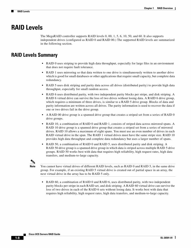
RAID LevelsThe MegaRAID controller supports RAID levels 0, 00, 1, 5, 6, 10, 50, and 60. It also supports independent drives (configured as RAID 0 and RAID 00.) The supported RAID levels are summarized in the following section.
RAID Levels Summary• RAID 0 uses striping to provide high data throughput, especially for large files in an environment
that does not require fault tolerance.
• RAID 1 uses mirroring so that data written to one drive is simultaneously written to another drive which is good for small databases or other applications that require small capacity, but complete data redundancy.
• RAID 5 uses disk striping and parity data across all drives (distributed parity) to provide high data throughput, especially for small random access.
• RAID 6 uses distributed parity, with two independent parity blocks per stripe, and disk striping. A RAID 6 virtual drive can survive the loss of two drives without losing data. A RAID 6 drive group, which requires a minimum of three drives, is similar to a RAID 5 drive group. Blocks of data and parity information are written across all drives. The parity information is used to recover the data if one or two drives fail in the drive group.
• A RAID 00 drive group is a spanned drive group that creates a striped set from a series of RAID 0 drive groups.
• RAID 10, a combination of RAID 0 and RAID 1, consists of striped data across mirrored spans. A RAID 10 drive group is a spanned drive group that creates a striped set from a series of mirrored drives. RAID 10 allows a maximum of eight spans. You must use an even number of drives in each RAID virtual drive in the span. The RAID 1 virtual drives must have the same stripe size. RAID 10 provides high data throughput and complete data redundancy but uses a larger number of spans.
• RAID 50, a combination of RAID 0 and RAID 5, uses distributed parity and disk striping. A RAID 50 drive group is a spanned drive group in which data is striped across multiple RAID 5 drive groups. RAID 50 works best with data that requires high reliability, high request rates, high data transfers, and medium-to-large capacity.
Note You cannot have virtual drives of different RAID levels, such as RAID 0 and RAID 5, in the same drive group. For example, if an existing RAID 5 virtual drive is created out of partial space in an array, the next virtual drive in the array has to be RAID 5 only.
• RAID 60, a combination of RAID 0 and RAID 6, uses distributed parity, with two independent parity blocks per stripe in each RAID set, and disk striping. A RAID 60 virtual drive can survive the loss of two drives in each of the RAID 6 sets without losing data. It works best with data that requires high reliability, high request rates, high data transfers, and medium-to-large capacity.
1-8Cisco UCS Servers RAID Guide
OL-26591-01

Chapter 1 RAID Overview RAID Levels
RAID 0RAID 0 provides disk striping across all drives in the RAID drive group. RAID 0 does not provide any data redundancy but does offer the best performance of any RAID level. RAID 0 breaks up data into smaller segments and stripes the data segments across each drive in the drive group. The size of each data segment is determined by the stripe size. RAID 0 offers high bandwidth.
Note RAID level 0 is not fault tolerant. If a drive in a RAID 0 drive group fails, the whole virtual drive (all drives associated with the virtual drive) will fail.
By breaking up a large file into smaller segments, the RAID controller can use both SAS drives and SATA drives to read or write the file faster. RAID 0 involves no parity calculations to complicate the write operation, which makes RAID 0 ideal for applications that require high bandwidth, but do not require fault tolerance. Table 1-4 provides an overview of RAID 0. Figure 1-5 shows an example of a RAID 0 drive group advantage.
Figure 1-5 RAID 0 Drive Group Example
Table 1-4 RAID 0 Overview
Feature Description
Uses Provides high data throughput, especially for large files. Any environment that does not require fault tolerance.
Benefits Provides increased data throughput for large files. No capacity loss penalty for parity.
Limitations Does not provide fault tolerance or high bandwidth.All data is lost if any drive fails.
Drives 1 to 32.
Segment 1
Segment 3Segment 5
Segment 2
Segment 4Segment 6
Segment 7 Segment 8 3320
88
1-9Cisco UCS Servers RAID Guide
OL-26591-01

Chapter 1 RAID Overview RAID Levels
RAID 1In RAID 1, the RAID controller duplicates all data from one drive to a second drive in the drive group. RAID 1 supports an even number of drives from 2 to 32 in a single span. RAID 1 provides complete data redundancy but at the cost of doubling the required data storage capacity. Table 1-5 provides an overview of RAID 1. Figure 1-6 shows an example of a RAID 1 drive group.
Figure 1-6 RAID 1 Drive Group Example
RAID 5RAID 5 includes disk striping at the block level and parity. Parity is the property of the data of being odd or even, and parity checking is used to detect errors in the data. In RAID 5, the parity information is written to all drives. RAID 5 is best suited for networks that perform a lot of small input/output (I/O) transactions simultaneously. RAID 5 provides data redundancy, high read rates, and good performance in most environments. It also provides redundancy with the lowest loss of capacity.
In addition, RAID 5 is good for any application that has high read request rates but has low write request rates.
RAID 5 addresses the congestion issue for random I/O operations. Because each drive contains both data and parity, numerous writes can take place concurrently.
Table 1-6 provides an overview of RAID 5. Figure 1-7 shows an example of a RAID 5 drive group.
Table 1-5 RAID 1 Overview
Feature Description
Uses Use RAID 1 for small databases or any other environment that requires fault tolerance, but small capacity.
Benefits Provides complete data redundancy. RAID 1 is ideal for any application that requires fault tolerance and minimal capacity.
Limitations Requires twice as many drives. Performance is impaired during drive rebuilds.
Drives 2 to 32 (must be an even number of drives).
Segment 1 Segment 1Duplicate Segment 2 Segment 3
DuplicateSegment 4Duplicate
Segment 3 Segment 4
Segment 5 Segment 6 Segment 7 Segment 8Segment 5Duplicate
Segment 6Duplicate
Segment 7Duplicate
Segment 8Duplicate
Segment 2Duplicate
... ... ... ...
RAID1 RAID1 RAID1 RAID1 3320
89
1-10Cisco UCS Servers RAID Guide
OL-26591-01
Chapter 1 RAID Overview RAID Levels
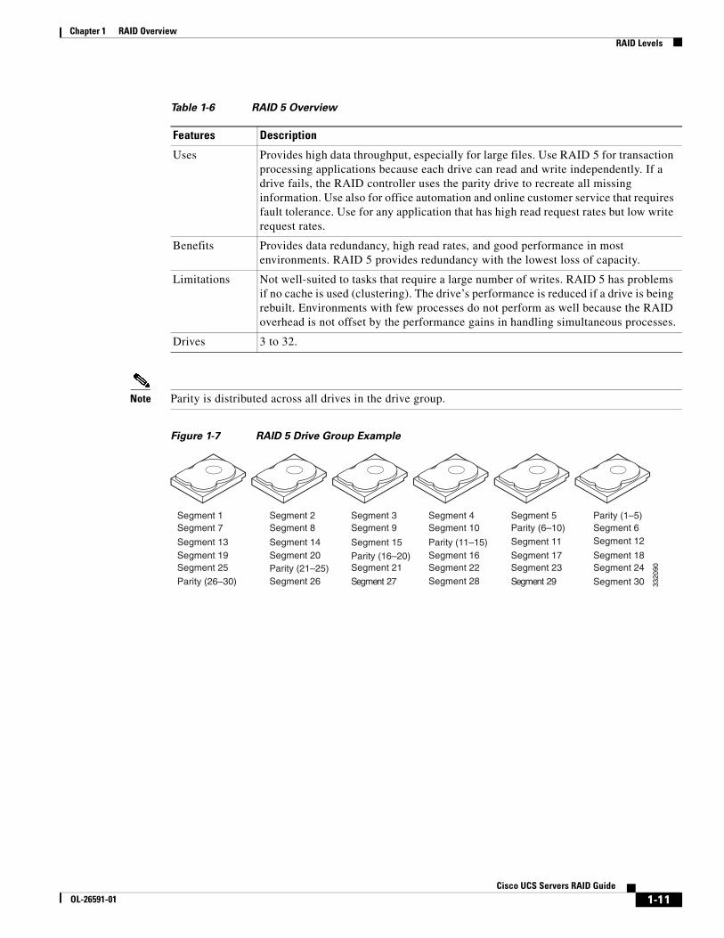
Note Parity is distributed across all drives in the drive group.
Figure 1-7 RAID 5 Drive Group Example
Table 1-6 RAID 5 Overview
Features Description
Uses Provides high data throughput, especially for large files. Use RAID 5 for transaction processing applications because each drive can read and write independently. If a drive fails, the RAID controller uses the parity drive to recreate all missing information. Use also for office automation and online customer service that requires fault tolerance. Use for any application that has high read request rates but low write request rates.
Benefits Provides data redundancy, high read rates, and good performance in most environments. RAID 5 provides redundancy with the lowest loss of capacity.
Limitations Not well-suited to tasks that require a large number of writes. RAID 5 has problems if no cache is used (clustering). The drive’s performance is reduced if a drive is being rebuilt. Environments with few processes do not perform as well because the RAID overhead is not offset by the performance gains in handling simultaneous processes.
Drives 3 to 32.
Segment 1Segment 7
Segment 2Segment 8
Segment 3Segment 9
Segment 4Segment 10
Segment 5Parity (6–10)
Parity (11–15)
Parity (1–5)Segment 6Segment 12Segment 15 Segment 11Segment 14Segment 13
Segment 19Segment 25
Segment 20Segment 23
Segment 18Segment 21
Segment 16Segment 22
Segment 17Parity (21–25)
Parity (26–30)
Parity (16–20)Segment 24
Segment 3092 tnemgeS72 tnemgeSSegment 26 Segment 28 3320
90
1-11Cisco UCS Servers RAID Guide
OL-26591-01
Chapter 1 RAID Overview RAID Levels
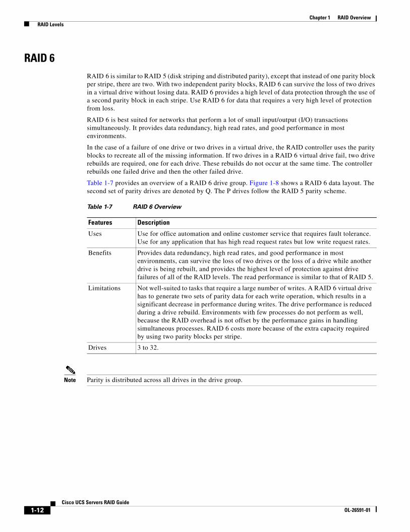
RAID 6RAID 6 is similar to RAID 5 (disk striping and distributed parity), except that instead of one parity block per stripe, there are two. With two independent parity blocks, RAID 6 can survive the loss of two drives in a virtual drive without losing data. RAID 6 provides a high level of data protection through the use of a second parity block in each stripe. Use RAID 6 for data that requires a very high level of protection from loss.
RAID 6 is best suited for networks that perform a lot of small input/output (I/O) transactions simultaneously. It provides data redundancy, high read rates, and good performance in most environments.
In the case of a failure of one drive or two drives in a virtual drive, the RAID controller uses the parity blocks to recreate all of the missing information. If two drives in a RAID 6 virtual drive fail, two drive rebuilds are required, one for each drive. These rebuilds do not occur at the same time. The controller rebuilds one failed drive and then the other failed drive.
Table 1-7 provides an overview of a RAID 6 drive group. Figure 1-8 shows a RAID 6 data layout. The second set of parity drives are denoted by Q. The P drives follow the RAID 5 parity scheme.
Note Parity is distributed across all drives in the drive group.
Table 1-7 RAID 6 Overview
Features Description
Uses Use for office automation and online customer service that requires fault tolerance. Use for any application that has high read request rates but low write request rates.
Benefits Provides data redundancy, high read rates, and good performance in most environments, can survive the loss of two drives or the loss of a drive while another drive is being rebuilt, and provides the highest level of protection against drive failures of all of the RAID levels. The read performance is similar to that of RAID 5.
Limitations Not well-suited to tasks that require a large number of writes. A RAID 6 virtual drive has to generate two sets of parity data for each write operation, which results in a significant decrease in performance during writes. The drive performance is reduced during a drive rebuild. Environments with few processes do not perform as well, because the RAID overhead is not offset by the performance gains in handling simultaneous processes. RAID 6 costs more because of the extra capacity required by using two parity blocks per stripe.
Drives 3 to 32.
1-12Cisco UCS Servers RAID Guide
OL-26591-01
Chapter 1 RAID Overview RAID Levels
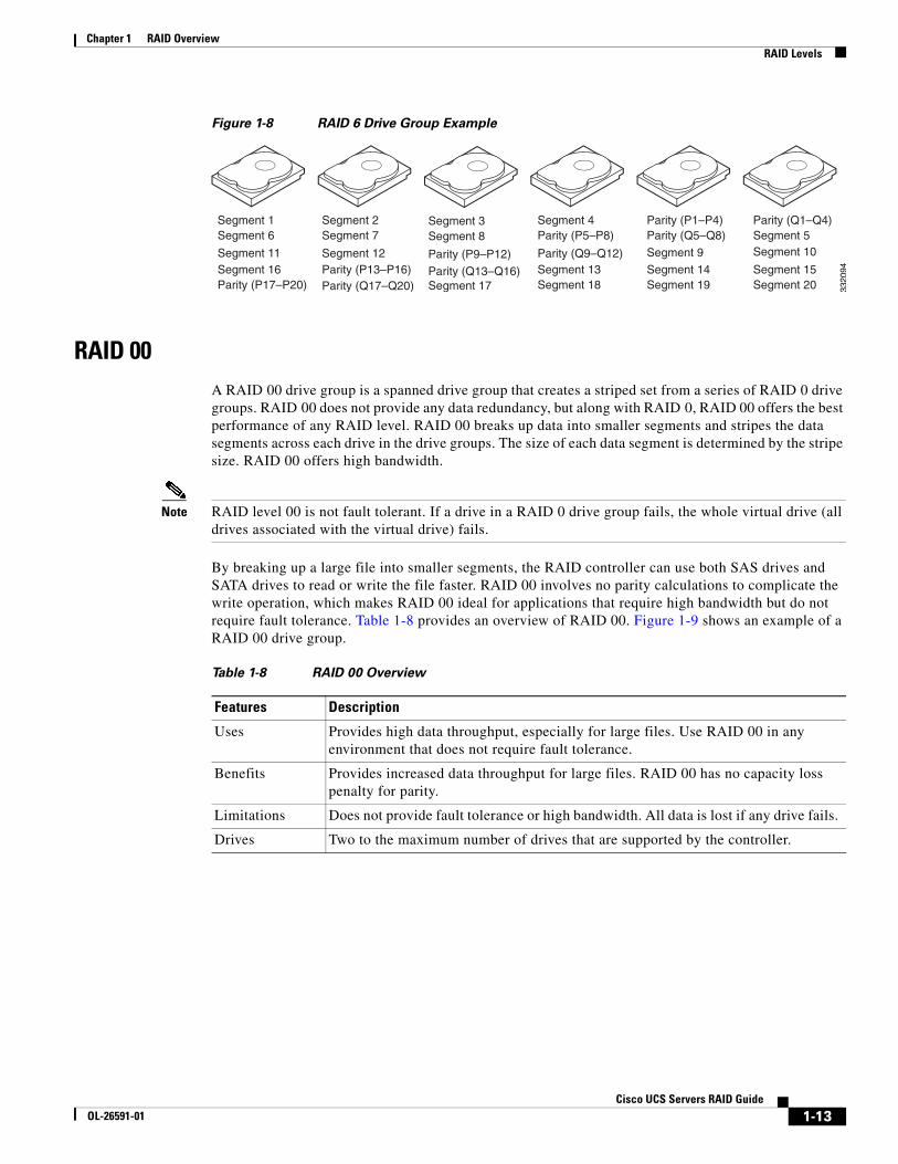
Figure 1-8 RAID 6 Drive Group Example
RAID 00A RAID 00 drive group is a spanned drive group that creates a striped set from a series of RAID 0 drive groups. RAID 00 does not provide any data redundancy, but along with RAID 0, RAID 00 offers the best performance of any RAID level. RAID 00 breaks up data into smaller segments and stripes the data segments across each drive in the drive groups. The size of each data segment is determined by the stripe size. RAID 00 offers high bandwidth.
Note RAID level 00 is not fault tolerant. If a drive in a RAID 0 drive group fails, the whole virtual drive (all drives associated with the virtual drive) fails.
By breaking up a large file into smaller segments, the RAID controller can use both SAS drives and SATA drives to read or write the file faster. RAID 00 involves no parity calculations to complicate the write operation, which makes RAID 00 ideal for applications that require high bandwidth but do not require fault tolerance. Table 1-8 provides an overview of RAID 00. Figure 1-9 shows an example of a RAID 00 drive group.
Segment 1Segment 6
Segment 2Segment 7
Segment 3Segment 8
Segment 4Parity (P5–P8)
Parity (P1–P4)Parity (Q5–Q8)
Parity (Q9–Q12)
Parity (Q1–Q4)Segment 5Segment 10Parity (P9–P12) Segment 9Segment 12Segment 11
Segment 16Parity (P17–P20)
Parity (P13–P16)Segment 19
Segment 15Segment 17
Segment 13Segment 18
Segment 14Parity (Q17–Q20)
Parity (Q13–Q16)Segment 20 33
2094
Table 1-8 RAID 00 Overview
Features Description
Uses Provides high data throughput, especially for large files. Use RAID 00 in any environment that does not require fault tolerance.
Benefits Provides increased data throughput for large files. RAID 00 has no capacity loss penalty for parity.
Limitations Does not provide fault tolerance or high bandwidth. All data is lost if any drive fails.
Drives Two to the maximum number of drives that are supported by the controller.
1-13Cisco UCS Servers RAID Guide
OL-26591-01
Chapter 1 RAID Overview RAID Levels
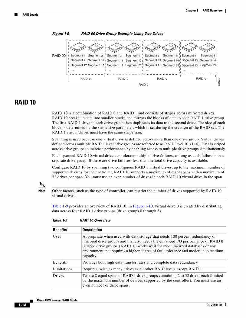
Figure 1-9 RAID 00 Drive Group Example Using Two Drives
RAID 10RAID 10 is a combination of RAID 0 and RAID 1 and consists of stripes across mirrored drives. RAID 10 breaks up data into smaller blocks and mirrors the blocks of data to each RAID 1 drive group. The first RAID 1 drive in each drive group then duplicates its data to the second drive. The size of each block is determined by the stripe size parameter, which is set during the creation of the RAID set. The RAID 1 virtual drives must have the same stripe size.
Spanning is used because one virtual drive is defined across more than one drive group. Virtual drives defined across multiple RAID 1 level drive groups are referred to as RAID level 10, (1+0). Data is striped across drive groups to increase performance by enabling access to multiple drive groups simultaneously.
Each spanned RAID 10 virtual drive can tolerate multiple drive failures, as long as each failure is in a separate drive group. If there are drive failures, less than the total drive capacity is available.
Configure RAID 10 by spanning two contiguous RAID 1 virtual drives, up to the maximum number of supported devices for the controller. RAID 10 supports a maximum of eight spans with a maximum of 32 drives per span. You must use an even number of drives in each RAID 10 virtual drive in the span.
Note Other factors, such as the type of controller, can restrict the number of drives supported by RAID 10 virtual drives.
Table 1-9 provides an overview of RAID 10. In Figure 1-10, virtual drive 0 is created by distributing data across four RAID 1 drive groups (drive groups 0 through 3).
Segment 1 Segment 2 Segment 3 Segment 6 Segment 8Segment 5 Segment 7
Segment 9 Segment 11 Segment 13 Segment 15 Segment 10 Segment 12 Segment 14 Segment 16
Segment 4
... ... ... ...
RAID 0 RAID 0 RAID 0 RAID 0
RAID 00
RAID 0
Segment 17 Segment 18 Segment 19 Segment 20 Segment 21 Segment 22 Segment 23 Segment 24
3320
95Table 1-9 RAID 10 Overview
Benefits Description
Uses Appropriate when used with data storage that needs 100 percent redundancy of mirrored drive groups and that also needs the enhanced I/O performance of RAID 0 (striped drive groups.) RAID 10 works well for medium-sized databases or any environment that requires a higher degree of fault tolerance and moderate to medium capacity.
Benefits Provides both high data transfer rates and complete data redundancy.
Limitations Requires twice as many drives as all other RAID levels except RAID 1.
Drives Two to 8 equal spans of RAID 1 drive groups containing 2 to 32 drives each (limited by the maximum number of devices supported by the controller). You must use an even number of drive spans.
1-14Cisco UCS Servers RAID Guide
OL-26591-01
Chapter 1 RAID Overview RAID Levels
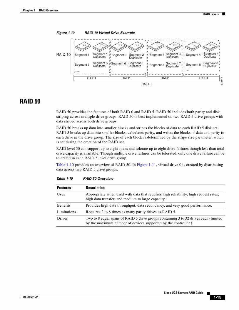
Figure 1-10 RAID 10 Virtual Drive Example
RAID 50RAID 50 provides the features of both RAID 0 and RAID 5. RAID 50 includes both parity and disk striping across multiple drive groups. RAID 50 is best implemented on two RAID 5 drive groups with data striped across both drive groups.
RAID 50 breaks up data into smaller blocks and stripes the blocks of data to each RAID 5 disk set. RAID 5 breaks up data into smaller blocks, calculates parity, and writes the blocks of data and parity to each drive in the drive group. The size of each block is determined by the stripe size parameter, which is set during the creation of the RAID set.
RAID level 50 can support up to eight spans and tolerate up to eight drive failures though less than total drive capacity is available. Though multiple drive failures can be tolerated, only one drive failure can be tolerated in each RAID 5 level drive group.
Table 1-10 provides an overview of RAID 50. In Figure 1-11, virtual drive 0 is created by distributing data across two RAID 5 drive groups.
Segment 1 Segment 1Duplicate
Segment 2 Segment 3Duplicate
Segment 4Duplicate
Segment 3 Segment 4
Segment 5 Segment 6 Segment 7 Segment 8Segment 5Duplicate
Segment 6Duplicate
Segment 7Duplicate
Segment 8Duplicate
Segment 2Duplicate
... ... ... ...
RAID1 RAID1 RAID1 RAID1
RAID 10
RAID 0 3321
43
Table 1-10 RAID 50 Overview
Features Description
Uses Appropriate when used with data that requires high reliability, high request rates, high data transfer, and medium to large capacity.
Benefits Provides high data throughput, data redundancy, and very good performance.
Limitations Requires 2 to 8 times as many parity drives as RAID 5.
Drives Two to 8 equal spans of RAID 5 drive groups containing 3 to 32 drives each (limited by the maximum number of devices supported by the controller.)
1-15Cisco UCS Servers RAID Guide
OL-26591-01

Chapter 1 RAID Overview RAID Levels
Figure 1-11 RAID 50 Virtual Drive Example
RAID 60RAID 60 provides the features of both RAID 0 and RAID 6 and includes both parity and disk striping across multiple drive groups. RAID 6 supports two independent parity blocks per stripe. A RAID 60 virtual drive can survive the loss of two drives in each of the RAID 6 sets without losing data. RAID 60 is best implemented on two RAID 6 drive groups with data striped across both drive groups.
RAID 60 breaks up data into smaller blocks and stripes the blocks of data to each RAID 6 disk set. RAID 6 breaks up data into smaller blocks, calculates parity, and writes the blocks of data and parity to each drive in the drive group. The size of each block is determined by the stripe size parameter, which is set during the creation of the RAID set.
RAID 60 can support up to 8 spans and tolerate up to 16 drive failures though less than total drive capacity is available. Two drive failures can be tolerated in each RAID 6 level drive group.
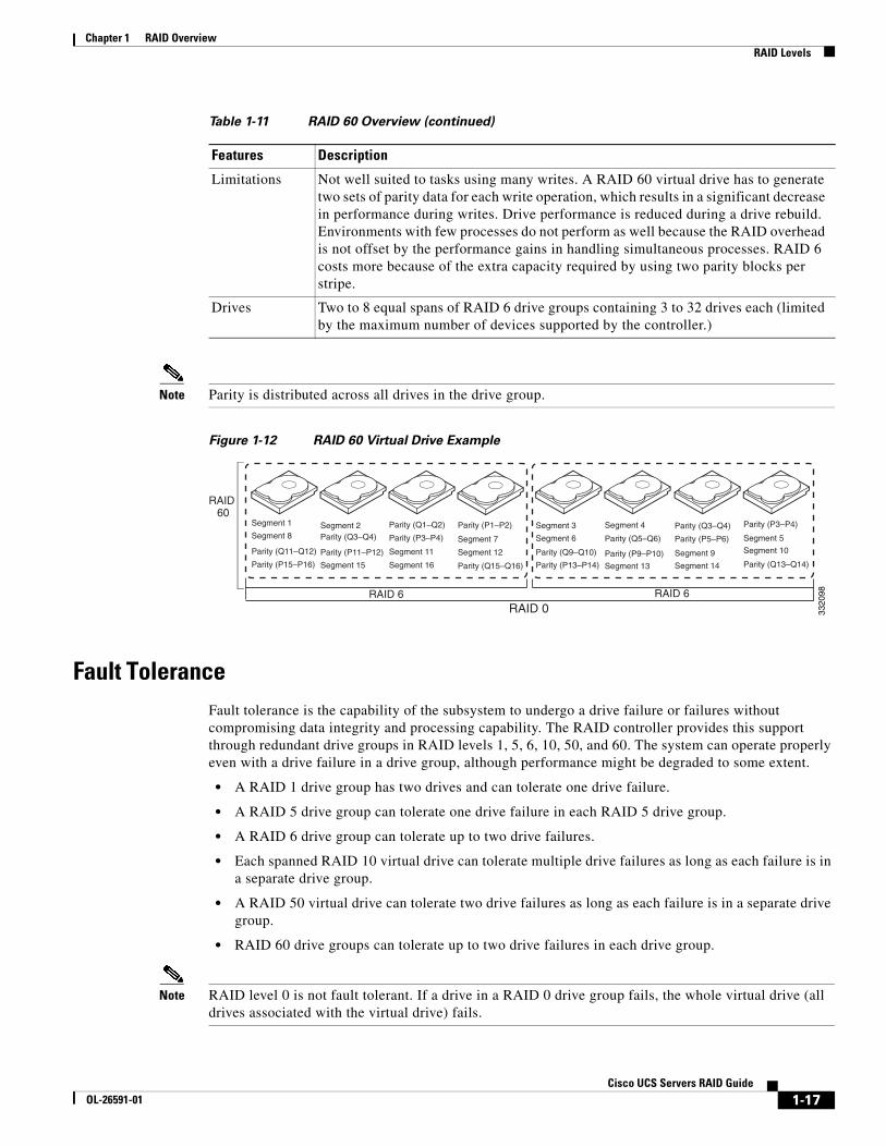
Table 1-11 provides an overview of RAID 60. Figure 1-12 shows a RAID 6 data layout. The second set of parity drives are denoted by Q. The P drives follow the RAID 5 parity scheme.
Segment 1 Segment 2
Segment 5Segment 6
RAID 0
RAID 50 (Segment 1,2) Segment 3 Segment 4
Segment 8 Segment 7
Segment 9 Segment 10 Segment 11 Segment 12
(Segment 5,6)
(Segment 9,10) (Segment 11,12)
(Segment 7,8)
(Segment 3,4)
RAID 5 RAID 5
3320
97
Table 1-11 RAID 60 Overview
Features Description
Uses Provides a high level of data protection through the use of a second parity block in each stripe. Use RAID 60 for data that requires a very high level of protection from loss.
In the case of a failure of one drive or two drives in a RAID set in a virtual drive, the RAID controller uses the parity blocks to recreate all of the missing information. If two drives in a RAID 6 set in a RAID 60 virtual drive fail, two drive rebuilds are required, one for each drive. These rebuilds can occur at the same time.
Use for office automation and online customer service that requires fault tolerance. Use for any application that has high read request rates but low write request rates.
Benefits Provides data redundancy, high read rates, and good performance in most environments. Each RAID 6 set can survive the loss of two drives or the loss of a drive while another drive is being rebuilt. RAID 60 provides the highest level of protection against drive failures of all of the RAID levels. The read performance is similar to that of RAID 50, though random reads in RAID 60 might be slightly faster because data is spread across at least one more disk in each RAID 6 set.
1-16Cisco UCS Servers RAID Guide
OL-26591-01
Chapter 1 RAID Overview RAID Levels
Note Parity is distributed across all drives in the drive group.
Figure 1-12 RAID 60 Virtual Drive Example
Fault ToleranceFault tolerance is the capability of the subsystem to undergo a drive failure or failures without compromising data integrity and processing capability. The RAID controller provides this support through redundant drive groups in RAID levels 1, 5, 6, 10, 50, and 60. The system can operate properly even with a drive failure in a drive group, although performance might be degraded to some extent.
• A RAID 1 drive group has two drives and can tolerate one drive failure.
• A RAID 5 drive group can tolerate one drive failure in each RAID 5 drive group.
• A RAID 6 drive group can tolerate up to two drive failures.
• Each spanned RAID 10 virtual drive can tolerate multiple drive failures as long as each failure is in a separate drive group.
• A RAID 50 virtual drive can tolerate two drive failures as long as each failure is in a separate drive group.
• RAID 60 drive groups can tolerate up to two drive failures in each drive group.
Note RAID level 0 is not fault tolerant. If a drive in a RAID 0 drive group fails, the whole virtual drive (all drives associated with the virtual drive) fails.
Limitations Not well suited to tasks using many writes. A RAID 60 virtual drive has to generate two sets of parity data for each write operation, which results in a significant decrease in performance during writes. Drive performance is reduced during a drive rebuild. Environments with few processes do not perform as well because the RAID overhead is not offset by the performance gains in handling simultaneous processes. RAID 6 costs more because of the extra capacity required by using two parity blocks per stripe.
Drives Two to 8 equal spans of RAID 6 drive groups containing 3 to 32 drives each (limited by the maximum number of devices supported by the controller.)
Table 1-11 RAID 60 Overview (continued)
Features Description
Segment 1
Segment 8Segment 2
Segment 7Segment 10
Segment 5
Parity (P1–P2)
Parity (Q11–Q12)
Parity (Q1–Q2)
Segment 11 Segment 12
Parity (P15–P16) Segment 15 Segment 16 Parity (Q15–Q16)
Segment 3
Segment 6
Segment 4
Parity (P9–P10)Parity (Q9–Q10)Parity (P11–P12) Segment 9Parity (P13–P14) Segment 14Segment 13 Parity (Q13–Q14)
RAID 6 RAID 6RAID 0
Parity (Q3–Q4) Parity (P3–P4)
Parity (Q5–Q6) Parity (P5–P6)Parity (P3–P4)Parity (Q3–Q4)
RAID60
3320
98
1-17Cisco UCS Servers RAID Guide
OL-26591-01
Chapter 1 RAID Overview Generic Drive Replacement Procedure
Fault tolerance is often associated with system availability because it allows the system to be available during the failures. However, it is also important for the system to be available during the repair of the problem.
Hot spares are important in fault tolerance; see Hot Spares, page 1-4 for more information.
Auto-rebuild allows a failed drive to be replaced and the data automatically rebuilt by hot swapping the drive in the same drive bay. See Hot Swap, page 1-6 for more information. The RAID drive group continues to handle requests while the rebuild occurs.
Generic Drive Replacement Procedure
Note B-series blade servers are shown but the mechanical features (release button, eject lever) are the same for most B-series and C-series servers.
Removing a Drive from a Server
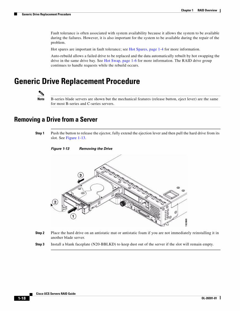
Step 1 Push the button to release the ejector, fully extend the ejection lever and then pull the hard drive from its slot. See Figure 1-13.
Figure 1-13 Removing the Drive
Step 2 Place the hard drive on an antistatic mat or antistatic foam if you are not immediately reinstalling it in another blade server.
Step 3 Install a blank faceplate (N20-BBLKD) to keep dust out of the server if the slot will remain empty.
1-18Cisco UCS Servers RAID Guide
OL-26591-01

Chapter 1 RAID Overview Platform-Specific RAID and Drive Procedures
Installing a Drive in a Server
Step 1 Place the hard drive lever into the open position by pushing the release button (see Figure 1-14).
Figure 1-14 Installing a Hard Drive in a Blade Server
Step 2 Gently slide the hard drive into the opening in the blade server until it seats into place.
Step 3 Push the hard drive lever into the closed position.
If you need to move a RAID cluster, see the Moving a RAID Cluster section of the “Troubleshooting Server Hardware” chapter of the Cisco UCS Troubleshooting Guide.
Platform-Specific RAID and Drive ProceduresB-series RAID and supported drive information that was previously in the software configuration, hardware installation and service, and troubleshooting guides is repeated in this guide. B series servers all have onboard RAID controllers that cannot be removed or upgraded. Only software configuration and drive operations appropriate for that server’s controller are possible.
Supported RAID controllers for all models are listed in RAID Controllers in UCS Servers, page 3-10.
The C-Series hardware installation guides each have a “RAID Considerations” appendix that provides information about supported RAID controllers and cables, plus cabling instructions specific to each server model. See that documentation as needed at:
http://www.cisco.com/en/US/products/ps10493/prod_installation_guides_list.html
1-19Cisco UCS Servers RAID Guide
OL-26591-01

Chapter 1 RAID Overview Platform-Specific RAID and Drive Procedures
1-20Cisco UCS Servers RAID Guide
OL-26591-01