Embed Size (px)
Citation preview

Lecture #2
Introduction to Power System Operation and Control using ARISTO
Davood Babazadeh
2015-09-04

2
Outline
Power system basics
Operational states
Power system control
– Active power and frequency
– Reactive power and voltage
Lab session

3
Course road map

Transport of electric power
Apparent power (Complex power) (S) [VA] – S=VI*=P+jQ – Electric power P [W] – Reactive Power Q [VAR]
Two ways to increase the transported power – Increase current I
• Larger conductor cross-section – Increase voltage U
• More insulation
Two ways to transport electricity – Alternating current (AC) – Direct current (DC)
4

Power network structure
Transmission system – all major generating stations and main
load centers – voltage levels (typically, 230 kV and
above).
Sub-transmission system – transmits the transmission substations
to the distribution substations. – Large industrial customers
Distribution system – power to the individual customers – between 4.0 kV and 34.5 kV
5

6
Operational states
Normal state, all system variables are within the normal range
Alert state, security level falls below a certain limit of adequacy because of a disturbance • generation shifting (security dispatch) , Increased reserve
Emergency state, severe disturbance • fault clearing, generation tripping, load curtailment
In extremis, cascading outages • load shedding and controlled system separation
Restorative state, control action is being taken to reconnect all the facilities and to restore system load.
Emergency
Alert
Normal
In Extremis
Restorative
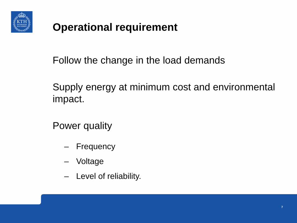
Operational requirement
Follow the change in the load demands
Supply energy at minimum cost and environmental impact.
Power quality
– Frequency
– Voltage
– Level of reliability.
7

Why constant frequency
Frequency fluctuations are harmful to electrical appliances.
– Speed of three phase ac motors proportional to the frequency. (N=120f/p)
– The blades of steam and water turbines are designed to operate at a particular speed. Frequency variation leads to speed variation and results in mechanical vibration
8

Why constant voltage
Over voltage and under voltage
– Electric motors will tend to run on over speed when they are fed with higher voltages resulting vibration and mechanical damage.
– Over voltage may also cause insulation failure.
– For a specified power rating, lower voltage results in more current and this results in heating problems. (P=VI)
9

Control parameters
Active Power and Frequency – Balance of load and generation
– Load-Frequency Control
Reactive Power and Voltage – Automatic voltage regulator
– capacitors and reactors
– Tap-changing transformers
10

Load & generation balance
Match between electric load and generation Frequency is an indication Balanced system, 50/60 Hz Net power surplus , frequency increases Net power shortage, frequency decreases
Generation Load
ΔP Δf
11

Generator
Generation side Control Demand side control
Governor Δf
Primary Control
Δf
Secondary Control
AGC/LFC ΔPtie
Connection and Tripping of power
Operator
UFLS
UCT
UUFLS
USec
U pri
dfdt
Emergency Control
Power System
f
Frequency control actions
12

13
Primary Frequency Control
• Generation is controlled by mechanical output of the prime mover
• The speed governor senses the change in speed (frequency)
• Actions taken within 5 – 30 seconds by generator droop control

14
Need of primary control reserves
UCTE 3000 MW (Continental Europe) – 3000 MW or equivalent of two 1500 MW nuclear plants or
lines trip at the same time
Eastern Interconnection (USA) – 3000 MW = largest interconnection
NORDEL (North Europe) – Continuous control = 600 MW/0.1 Hz – Frequency response = 1000 MW, if frequency drop to
49,5 – 49,9 Hz

15
Secondary control reserves Should reset the primary control reserves in 5 – 15 minutes to be ready for next disturbance Should correct the frequency deviation within allowable limit
• +/- 0.1 Hz in Nordel • +/- 0.2 Hz in UCTE

16
Supplementary/Secondary Control
Frequency deviation feedback PI or I controller Connected to economic dispatch system

Under frequency Load Shedding (UFLS)
To prevent extended operation of separated areas at low frequency, load shedding schemes are employed. A typical scheme for USA:
• 10% load shed when frequency drops to 59.2 Hz • 15% additional load shed when frequency drops to 58.8 Hz • 20% additional load shed when frequency reaches 58.0 Hz
17

Example
18

Voltage Control
Control of voltage levels is carried out by controlling the production, absorption, and flow of reactive power
Generating units provide the basic means of voltage control. synchronous generators
– can generate or absorb Q depending on excitation
– automatic voltage regulator continuously adjusts excitation
to control armature voltage
– primary source of voltage support
19

Voltage Control
Additional means are usually required to control voltage throughout the system:
– sources or sinks of reactive power, such as shunt capacitors, shunt reactors, synchronous condensers, and static var compensators (SVCs)
– line reactance compensators, such as series capacitors
– regulating transformers, such as tap-changing transformers and boosters
20

Example: Shunt Compensation
21
a) shunt compensation
b) phasor diagram without compensation
c) phasor diagram with compensation

Introduction to LAB 1
Using ARISTO
22

Aim of Lab1
To introduce – Basic operational phenomena in a typical power system
– Corresponding countermeasures
– Real time simulations
– Dynamic behaviour of power system
23

What is ARISTO
The ARISTO system is a fast, interactive power system dynamics simulator for learning and analysis.
The simulator is capable of real-time simulation of large systems.
Simulation of very large systems is possible with a slower simulation speed.
The phenomena to be simulated are:
• Transient stability. • Long term dynamics. • Voltage stability.
24
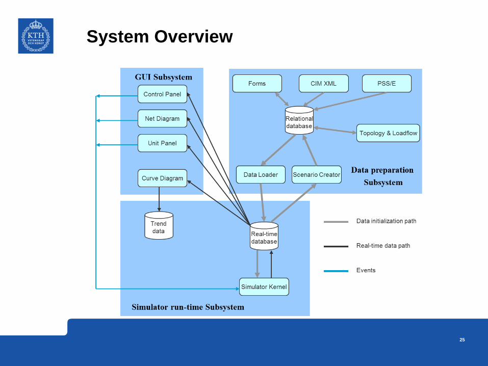
System Overview
25

26
What can be modeled?
1 s 10 -2 10 -3 10 -4 10 10 -1 10 2 10 3
Load Frequency Control
Turbine & Boiler Control
Generator Excitation Control
Special Protection Systems
Protective Relay Systems
HVDC & SVC
Surge
Harmonics
Frequency Variations
Power Swing
Sub Synchronous Resonance
Equipment
Phenomena

27
Exercises - Scenarios
Task 1: Voltage Support • Injection / Consumption of reactive power
Task 2: Voltage Collapse in a power system (N-1 Operation) • Operation of Line Distance Protection (LDP) relays
• Islanding of power system due to voltage instability
Task 3: Frequency control along with load shedding • Primary Frequency Control (Governor Droop Characteristics)
• Secondary Frequency Control (Manual)
• Under Frequency Load Shedding

28
Exercises - Model • Simulations are performed with NORDIC 32 test system

29
Nordic 32 system description
Buses 32 Buses 21 PV buses, 10 PQ buses, 1 Slack bus 19 buses 400kV, 11 buses 135kV, 2 buses 220kV Transmission lines 52 Lines 33 Lines in 400kV, 17 Lines in 135kV and 2 Lines in 220kV Loads 21 buses have loads connected to them Generators 39 Generators 23 Hydro stations, 15 Thermal Stations and 1 Synchronous compensator 21 buses have generators Shunts 22 buses have shunts connected 3 buses have both shunt reactors and shunt capacitors 11 buses have shunt reactors alone, 8 buses have shunt capacitors alone
MittSV
Norr ExternActive Production: 3778 MWActive Load: -1181 MW
Active Production: 3429 MWActive Load: -6084 MW
Active Production: 2301 MWActive Load: -2300 MW
Active Production: 1753 MWActive Load: -1391 MW
2412 MW
1 MW
340 MW

30
Exercises - Outcome
• Getting started with ARISTO real time simulator
• Operation and control of a typical power system
• Voltage stability
• Operation of Line Distance Protection (LDP) relays
• Primary and Secondary Frequency control

Question?
31