Embed Size (px)
Citation preview

Page 1 of 172
Introduction to PanelView Programming
using FactoryTalk View Studio
(Machine Edition) Software
Page 2 of 172
Notice:
The information contained in this manual contains excerpts from Rockwell Automation user
manuals and is not meant to replace the complete documents. As such, this manual may not
contain all the safety precautions or all of the information necessary to configure your
automation system that is available in the complete user manuals. Please refer to the full
product installation and user documentation, paying particular attention to all safety
precautions prior to implementation.
The examples shown in this manual are for educational purposes only. Any individual or
company utilizing these examples in a control system does so at their own risk and agrees to
hold Van Meter Industrial harmless from any loss, accident, or injury resulting from the use of
these examples.
All Rockwell Automation information included in this manual is reproduced with the permission
of Rockwell Automation, Copyright © 2002 - 2012 Rockwell Automation. All rights reserved.
Page 3 of 172
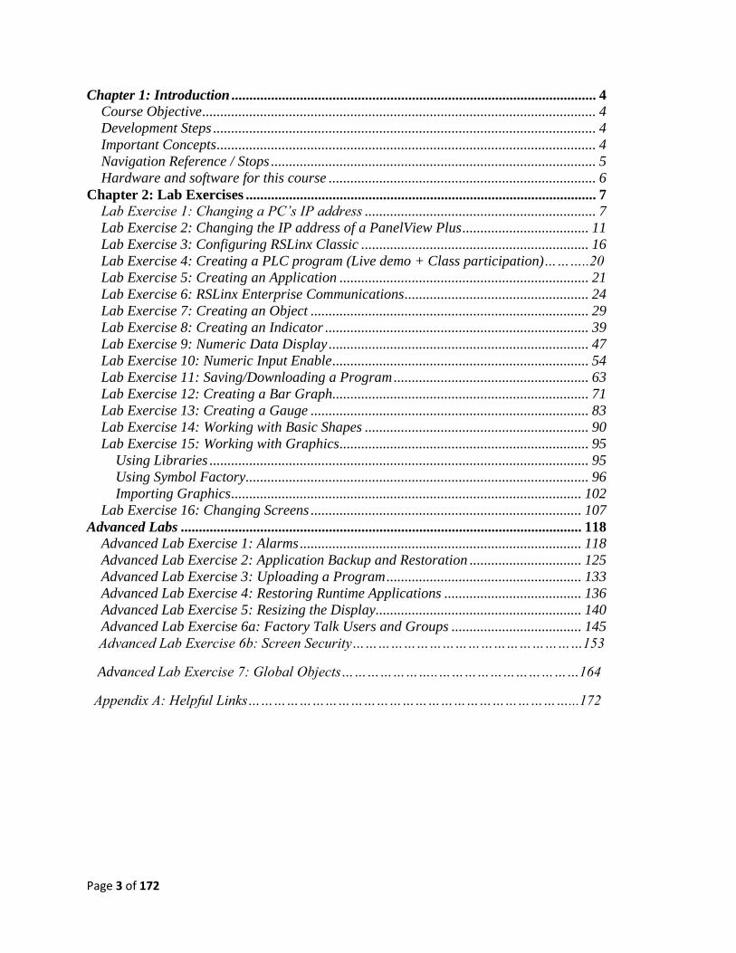
Chapter 1: Introduction ..................................................................................................... 4 Course Objective ............................................................................................................. 4 Development Steps .......................................................................................................... 4 Important Concepts ......................................................................................................... 4
Navigation Reference / Stops .......................................................................................... 5 Hardware and software for this course .......................................................................... 6
Chapter 2: Lab Exercises ................................................................................................. 7 Lab Exercise 1: Changing a PC’s IP address ................................................................ 7 Lab Exercise 2: Changing the IP address of a PanelView Plus ................................... 11
Lab Exercise 3: Configuring RSLinx Classic ............................................................... 16 Lab Exercise 4: Creating a PLC program (Live demo + Class participation)………..20
Lab Exercise 5: Creating an Application ..................................................................... 21 Lab Exercise 6: RSLinx Enterprise Communications ................................................... 24 Lab Exercise 7: Creating an Object ............................................................................. 29
Lab Exercise 8: Creating an Indicator ......................................................................... 39
Lab Exercise 9: Numeric Data Display ........................................................................ 47 Lab Exercise 10: Numeric Input Enable ....................................................................... 54
Lab Exercise 11: Saving/Downloading a Program ...................................................... 63 Lab Exercise 12: Creating a Bar Graph....................................................................... 71 Lab Exercise 13: Creating a Gauge ............................................................................. 83
Lab Exercise 14: Working with Basic Shapes .............................................................. 90 Lab Exercise 15: Working with Graphics ..................................................................... 95
Using Libraries ......................................................................................................... 95 Using Symbol Factory............................................................................................... 96 Importing Graphics ................................................................................................. 102
Lab Exercise 16: Changing Screens ........................................................................... 107
Advanced Labs ............................................................................................................... 118 Advanced Lab Exercise 1: Alarms .............................................................................. 118 Advanced Lab Exercise 2: Application Backup and Restoration ............................... 125
Advanced Lab Exercise 3: Uploading a Program ...................................................... 133 Advanced Lab Exercise 4: Restoring Runtime Applications ...................................... 136
Advanced Lab Exercise 5: Resizing the Display ......................................................... 140 Advanced Lab Exercise 6a: Factory Talk Users and Groups .................................... 145
Advanced Lab Exercise 6b: Screen Security………………………………………………153
Advanced Lab Exercise 7: Global Objects…………………..……………………………164
Appendix A: Helpful Links…………………………………………………………………...172
Page 4 of 172
Chapter 1: Introduction
Course Objective:
Provide the user with the basic skills necessary to operate, maintain, and develop applications
for the PanelView Plus human machine interface. These include, but are not limited to: creation
and implementation of various interface objects, application development, and handling of
data received from an external source. At the conclusion of this course, the user should be
familiar with all these tasks and have basic knowledge to implement these skills in their
respective applications.
Development Steps
This course contains many tasks that are to be completed in a specific order. When this is
necessary, a text box will be present with the step number indicated on the left-hand side.
These steps should be completed in logical numeric order, counting up from 1 (i.e. 1, 2, 3, …).
An example of this box, indicating the first step in a series, can be seen below.
Important Concepts
Important information that is relevant to the topic at hand will be denoted by an image of a
light bulb within a colored text box with text explaining important concepts or other
information. An example of such a text box can be seen below.
1
Page 5 of 172
Stops
At the end of each lab, there will be a symbol signifying that you need to stop and wait for the
instructor to tell you to proceed. During this time feel free to explore the software and practice
what the previous lab had you do, also answer any review questions.
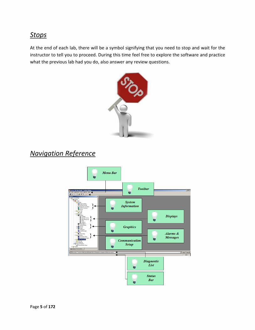
Navigation Reference
Page 6 of 172
Hardware and software for this Course
Hardware:
CompactLogix L3Y Demo case or CompactLogix L43 Demo case
PanelView Plus 6 (Terminal size may vary)
Software:
Studio 5000 - Version 21.XX or RSLogix 5000 Version 20.XX
FactoryTalk View Studio Machine Edition - Version 7.0 or 8.0
Computer Operating System – Windows 7 64-bit Virtual Machine
Page 7 of 172
Chapter 2: Lab Exercises
Lab 1: Changing your PC’s IP address
Objective: Teach the user how to change the IP address of a given PC. This is a must when
working with an Ethernet network. All devices that you want to network must be on the same
Ethernet sub-network, but each device must have a unique address as there can be no
duplicates.
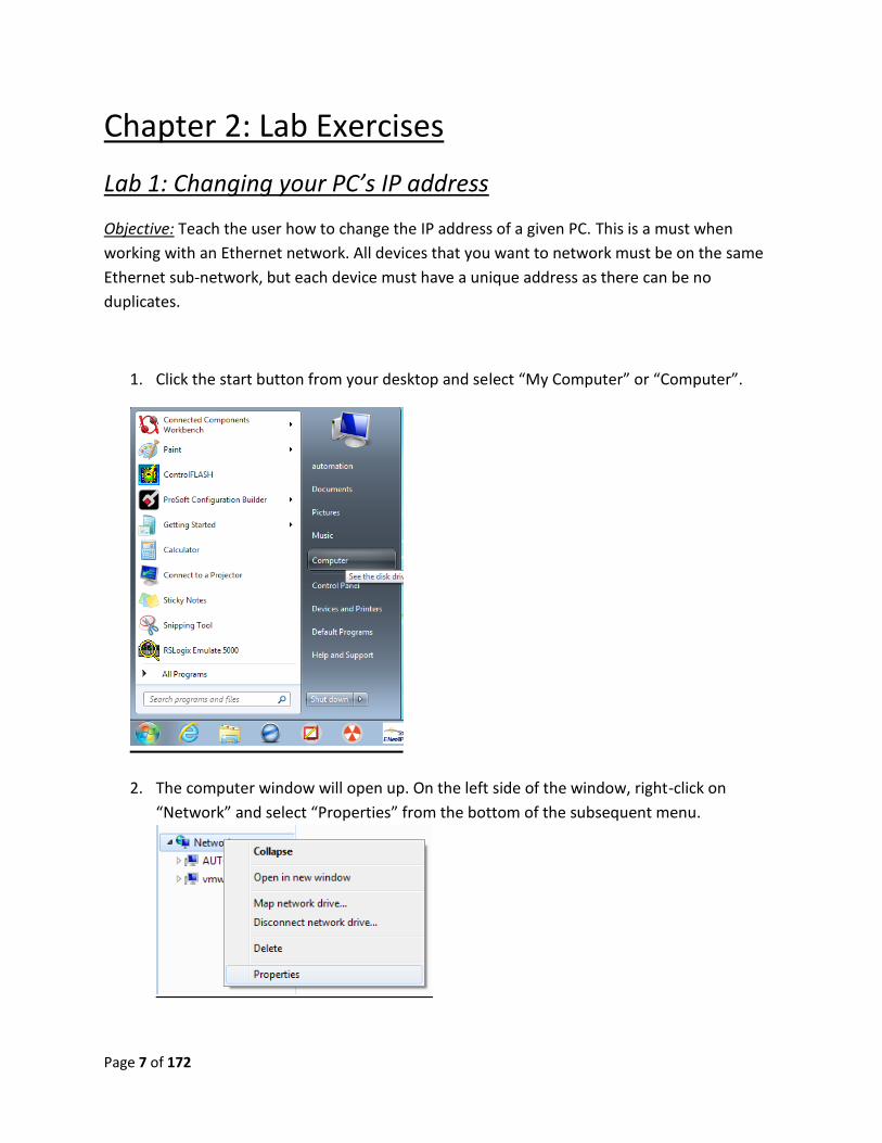
1. Click the start button from your desktop and select “My Computer” or “Computer”.
2. The computer window will open up. On the left side of the window, right-click on
“Network” and select “Properties” from the bottom of the subsequent menu.
Page 8 of 172
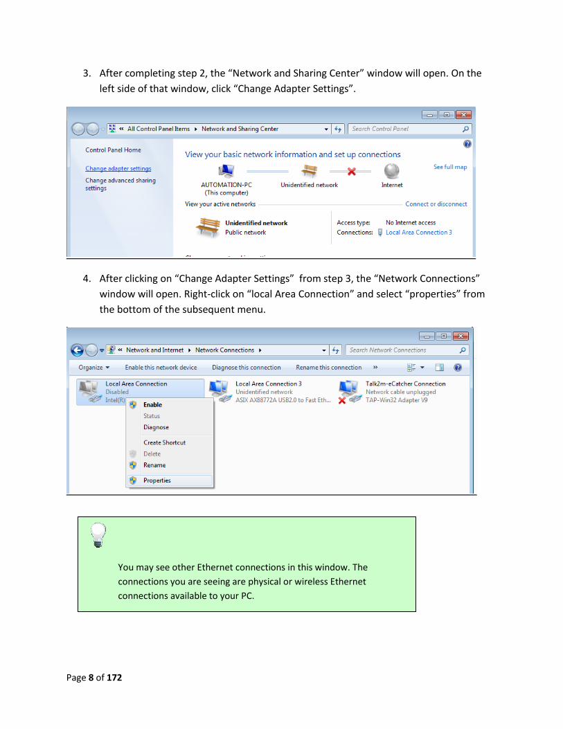
3. After completing step 2, the “Network and Sharing Center” window will open. On the
left side of that window, click “Change Adapter Settings”.
4. After clicking on “Change Adapter Settings” from step 3, the “Network Connections”
window will open. Right-click on “local Area Connection” and select “properties” from
the bottom of the subsequent menu.
You may see other Ethernet connections in this window. The
connections you are seeing are physical or wireless Ethernet
connections available to your PC.
Page 9 of 172
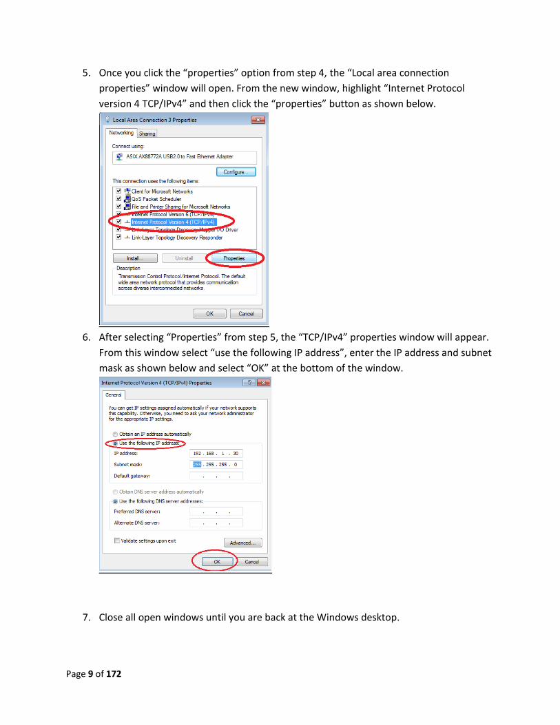
5. Once you click the “properties” option from step 4, the “Local area connection
properties” window will open. From the new window, highlight “Internet Protocol
version 4 TCP/IPv4” and then click the “properties” button as shown below.
6. After selecting “Properties” from step 5, the “TCP/IPv4” properties window will appear.
From this window select “use the following IP address”, enter the IP address and subnet
mask as shown below and select “OK” at the bottom of the window.
7. Close all open windows until you are back at the Windows desktop.
Page 10 of 172
Lab 1 Review:
1. What does a subnet mask do?
2. Can you have two devices with the same IP address on a given subnet mask?
3. What is a quick way to check the IP address of your PC (Hint: CMD)
This completes Lab 1. Please wait for instructions to proceed further.
Page 11 of 172
Lab 2: Changing the IP address of a PanelView Plus
Objective: To teach user how to change the IP address of a PanelView Plus terminal.
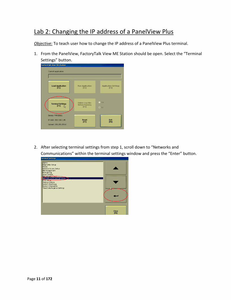
1. From the PanelView, FactoryTalk View ME Station should be open. Select the “Terminal
Settings” button.
2. After selecting terminal settings from step 1, scroll down to “Networks and
Communications” within the terminal settings window and press the “Enter” button.
Page 12 of 172
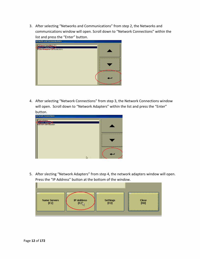
3. After selecting “Networks and Communications” from step 2, the Networks and
communications window will open. Scroll down to “Network Connections” within the
list and press the “Enter” button.
4. After selecting “Network Connections” from step 3, the Network Connections window
will open. Scroll down to “Network Adapters” within the list and press the “Enter”
button.
5. After slecting “Network Adapters” from step 4, the network adapters window will open.
Press the “IP Address” button at the bottom of the window.
Page 13 of 172
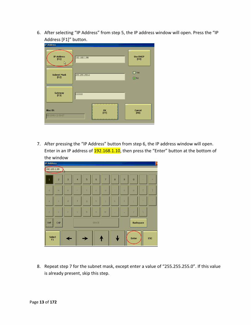
6. After selecting “IP Address” from step 5, the IP address window will open. Press the “IP
Address [F1]” button.
7. After pressing the “IP Address” button from step 6, the IP address window will open.
Enter in an IP address of 192.168.1.10, then press the “Enter” button at the bottom of
the window
8. Repeat step 7 for the subnet mask, except enter a value of “255.255.255.0”. If this value
is already present, skip this step.
Page 14 of 172
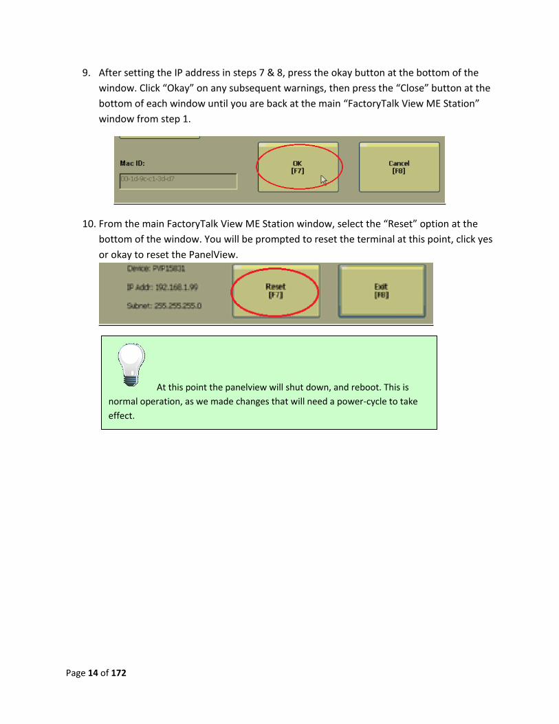
9. After setting the IP address in steps 7 & 8, press the okay button at the bottom of the
window. Click “Okay” on any subsequent warnings, then press the “Close” button at the
bottom of each window until you are back at the main “FactoryTalk View ME Station”
window from step 1.
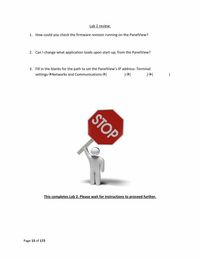
10. From the main FactoryTalk View ME Station window, select the “Reset” option at the
bottom of the window. You will be prompted to reset the terminal at this point, click yes
or okay to reset the PanelView.
At this point the panelview will shut down, and reboot. This is
normal operation, as we made changes that will need a power-cycle to take
effect.
Page 15 of 172
Lab 2 review:
1. How could you check the firmware revision running on the PanelView?
2. Can I change what application loads upon start-up, from the PanelView?
3. Fill in the blanks for the path to set the PanelView’s IP address: Terminal
settingsNetworks and Communications( )( )( )
This completes Lab 2. Please wait for Instructions to proceed further.
Page 16 of 172
Lab 3: RSLinx Classic Ethernet/IP Driver Setup
Objective: To teach the user the differences between Ethernet drivers, how to navigate RSLinx
classic and how to utilize RSLinx Classic with Studio 5000 / FactoryTalk View Studio.
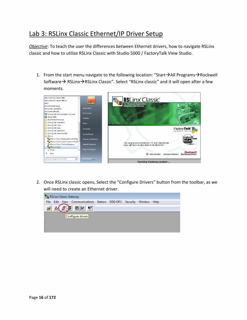
1. From the start menu navigate to the following location: “StartAll ProgramsRockwell
Software RSLinxRSLinx Classic”. Select “RSLinx classic” and it will open after a few
moments.
2. Once RSLinx classic opens, Select the “Configure Drivers” button from the toolbar, as we
will need to create an Ethernet driver.
Page 17 of 172
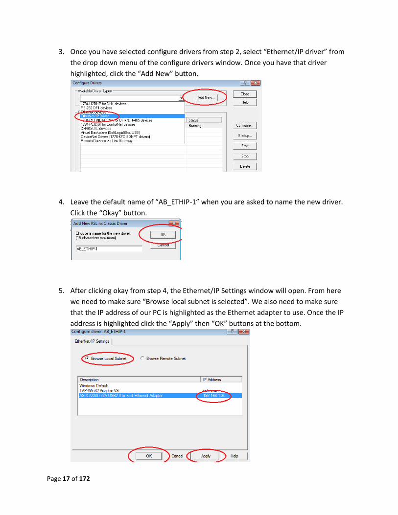
3. Once you have selected configure drivers from step 2, select “Ethernet/IP driver” from
the drop down menu of the configure drivers window. Once you have that driver
highlighted, click the “Add New” button.
4. Leave the default name of “AB_ETHIP-1” when you are asked to name the new driver.
Click the “Okay” button.
5. After clicking okay from step 4, the Ethernet/IP Settings window will open. From here
we need to make sure “Browse local subnet is selected”. We also need to make sure
that the IP address of our PC is highlighted as the Ethernet adapter to use. Once the IP
address is highlighted click the “Apply” then “OK” buttons at the bottom.
Page 18 of 172
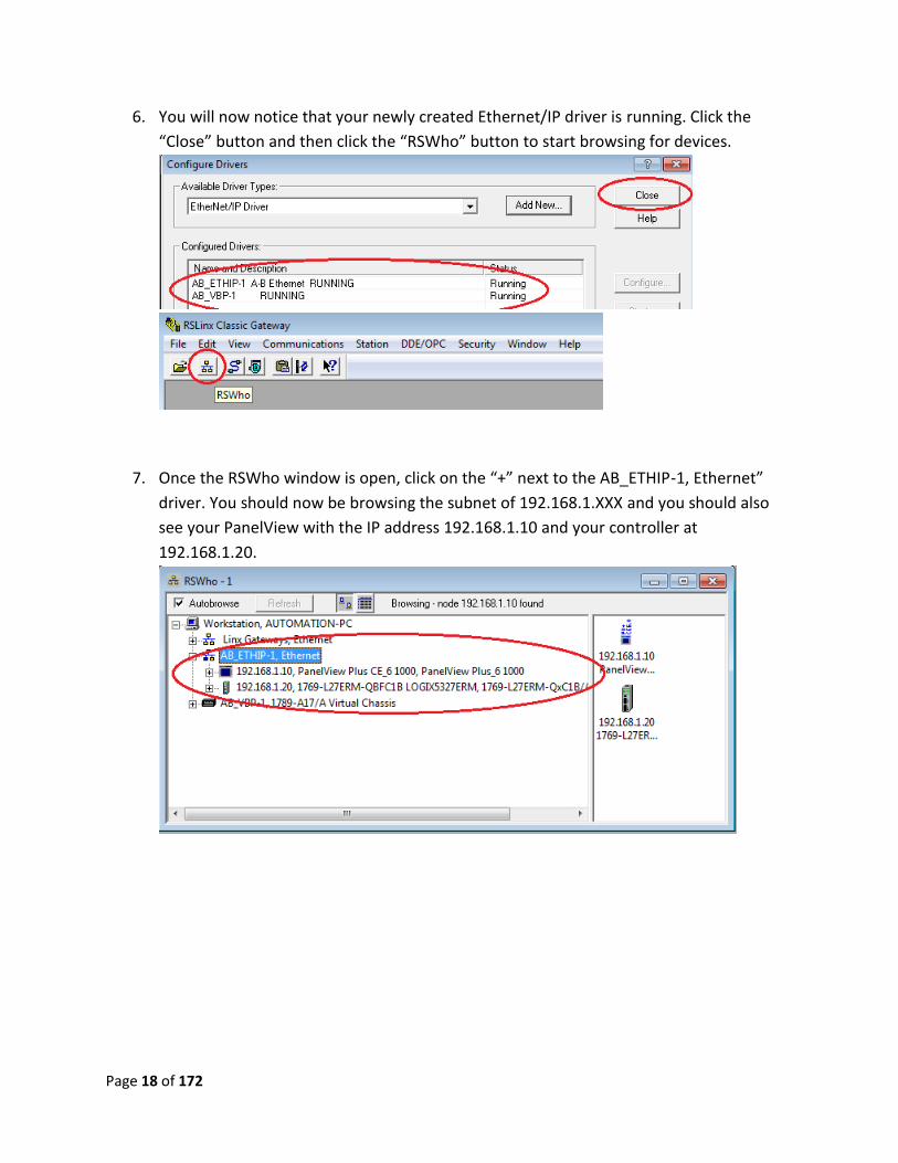
6. You will now notice that your newly created Ethernet/IP driver is running. Click the
“Close” button and then click the “RSWho” button to start browsing for devices.
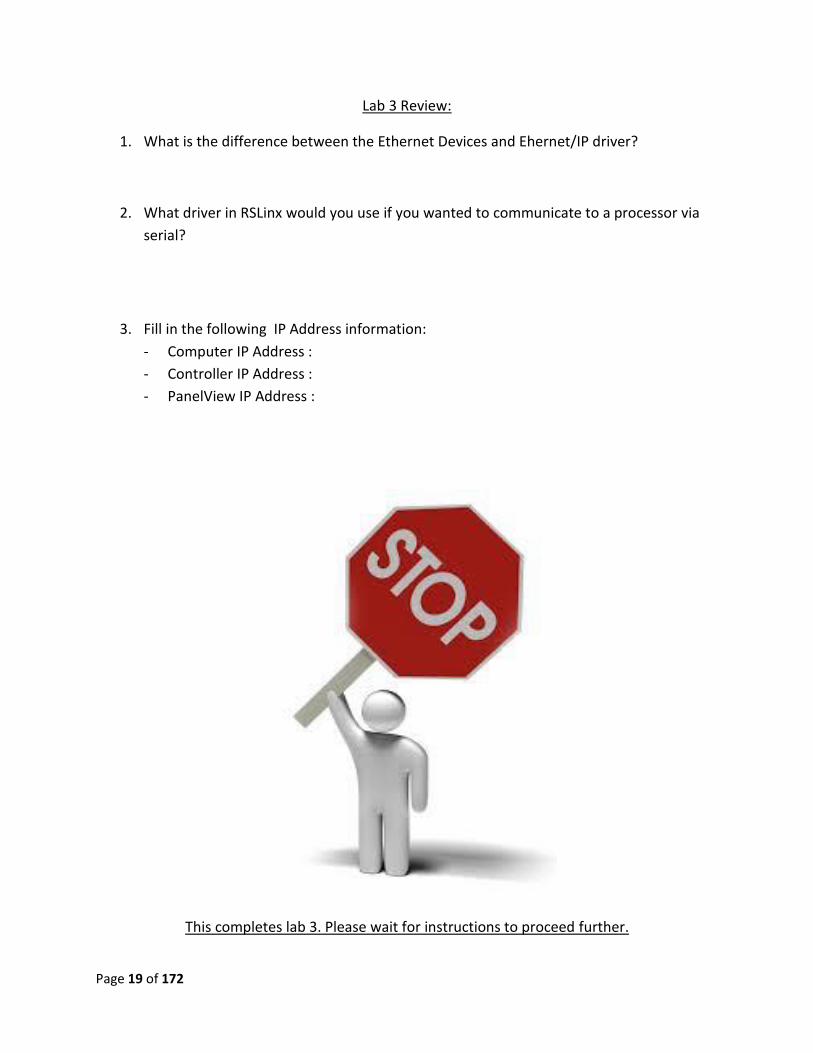
7. Once the RSWho window is open, click on the “+” next to the AB_ETHIP-1, Ethernet”
driver. You should now be browsing the subnet of 192.168.1.XXX and you should also
see your PanelView with the IP address 192.168.1.10 and your controller at
192.168.1.20.
Page 19 of 172
Lab 3 Review:
1. What is the difference between the Ethernet Devices and Ehernet/IP driver?
2. What driver in RSLinx would you use if you wanted to communicate to a processor via
serial?
3. Fill in the following IP Address information:
- Computer IP Address :
- Controller IP Address :
- PanelView IP Address :
This completes lab 3. Please wait for instructions to proceed further.
Page 20 of 172
Lab 4: Creating a PLC program & I/O configuration
1. This lab will consist of a live demo by the instructors. We will look briefly at the demo
code created for this lab.
Lab 4 review
1. How would someone look up the firmware revision of an I/O module?
2. Where do I establish the communication path between my PLC and PanelView?
This completes lab 4. Please wait for instructions to proceed further.
Page 21 of 172
Lab 5: Creating an application
Objective: To familiarize the user with basic FactoryTalk View Studio operation, such as opening
the program and creating a new application. This will enable the user to create the specific
PanelView application they will configure in the following labs.
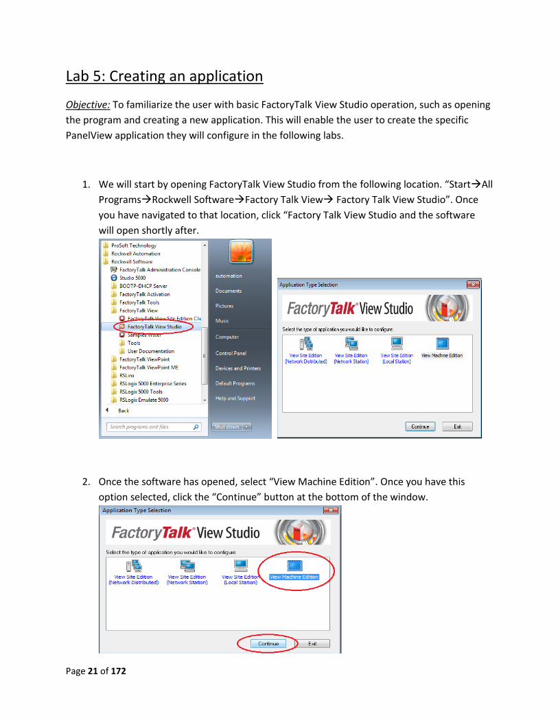
1. We will start by opening FactoryTalk View Studio from the following location. “StartAll
ProgramsRockwell SoftwareFactory Talk View Factory Talk View Studio”. Once
you have navigated to that location, click “Factory Talk View Studio and the software
will open shortly after.
2. Once the software has opened, select “View Machine Edition”. Once you have this
option selected, click the “Continue” button at the bottom of the window.
Page 22 of 172
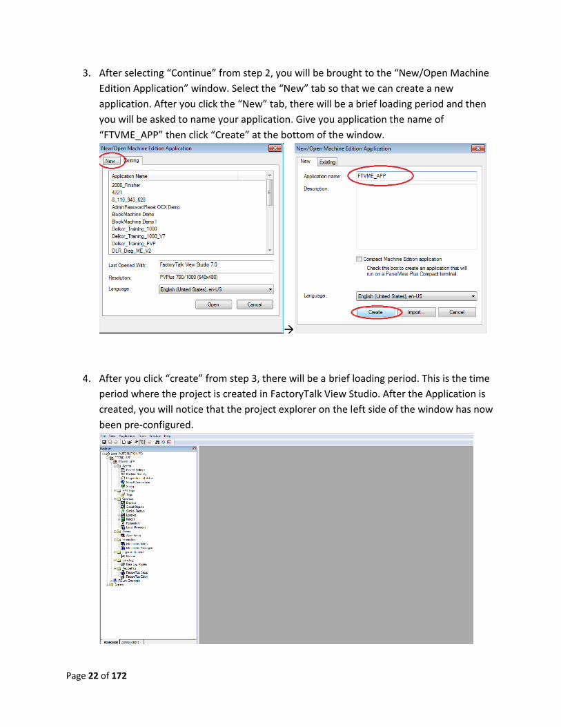
3. After selecting “Continue” from step 2, you will be brought to the “New/Open Machine
Edition Application” window. Select the “New” tab so that we can create a new
application. After you click the “New” tab, there will be a brief loading period and then
you will be asked to name your application. Give you application the name of
“FTVME_APP” then click “Create” at the bottom of the window.
4. After you click “create” from step 3, there will be a brief loading period. This is the time
period where the project is created in FactoryTalk View Studio. After the Application is
created, you will notice that the project explorer on the left side of the window has now
been pre-configured.

Page 23 of 172
Lab 5 Review
1. Where would you find the communication settings between the PLC and PanelView?
2. Is there a way to configure security for screens and users?
3. How do you create a new display?
This now completes lab 5. Please wait for instructions to proceed further.
Page 24 of 172
Lab 6: RSLinx Enterprise Communications Setup
Objective: Teach the user about configuration of RSLinx Enterprise Communications. This allows
for downloading and uploading of user-created applications over a network. This also
established the link or “path” between a controller and PanelView. At the end of this lab, the
user will have configured their PanelView to communicate easily with the PLC.
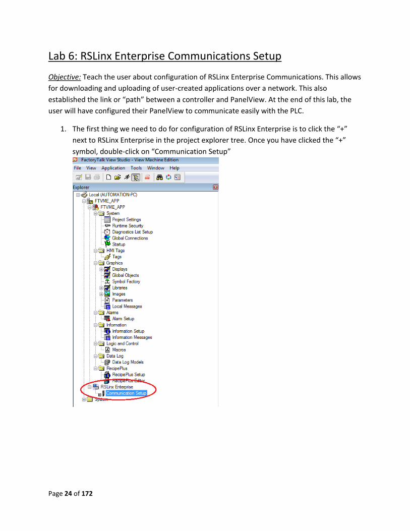
1. The first thing we need to do for configuration of RSLinx Enterprise is to click the “+”
next to RSLinx Enterprise in the project explorer tree. Once you have clicked the “+”
symbol, double-click on “Communication Setup”
Page 25 of 172
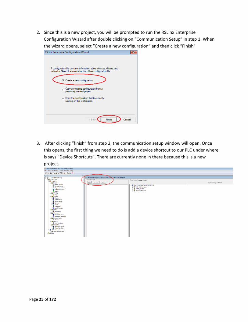
2. Since this is a new project, you will be prompted to run the RSLinx Enterprise
Configuration Wizard after double clicking on “Communication Setup” in step 1. When
the wizard opens, select “Create a new configuration” and then click “Finish”
3. After clicking “finish” from step 2, the communication setup window will open. Once
this opens, the first thing we need to do is add a device shortcut to our PLC under where
is says “Device Shortcuts”. There are currently none in there because this is a new
project.
Page 26 of 172
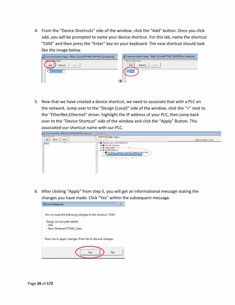
4. From the “Device Shortcuts” side of the window, click the “Add” button. Once you click
add, you will be prompted to name your device shortcut. For this lab, name the shortcut
“CMX” and then press the “Enter” key on your keyboard. The new shortcut should look
like the image below.
5. Now that we have created a device shortcut, we need to associate that with a PLC on
the network. Jump over to the “Design [Local]” side of the window, click the “+” next to
the “EtherNet,Ethernet” driver, highlight the IP address of your PLC, then jump back
over to the “Device Shortcut” side of the window and click the “Apply” Button. This
associated our shortcut name with our PLC.
6. After clicking “Apply” from step 5, you will get an informational message stating the
changes you have made. Click “Yes” within the subsequent message.
Page 27 of 172
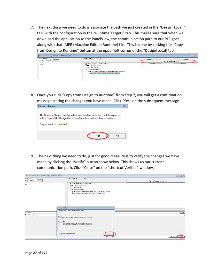
7. The next thing we need to do is associate the path we just created in the “Design[Local]”
tab, with the configuration in the “Runtime[Target]” tab. This makes sure that when we
download the application to the PanelView, the communication path to our PLC goes
along with that .MER (Machine Edition Runtime) file. This is done by clicking the “Copy
from Design to Runtime” button at the upper left corner of the “Design[Local] tab.
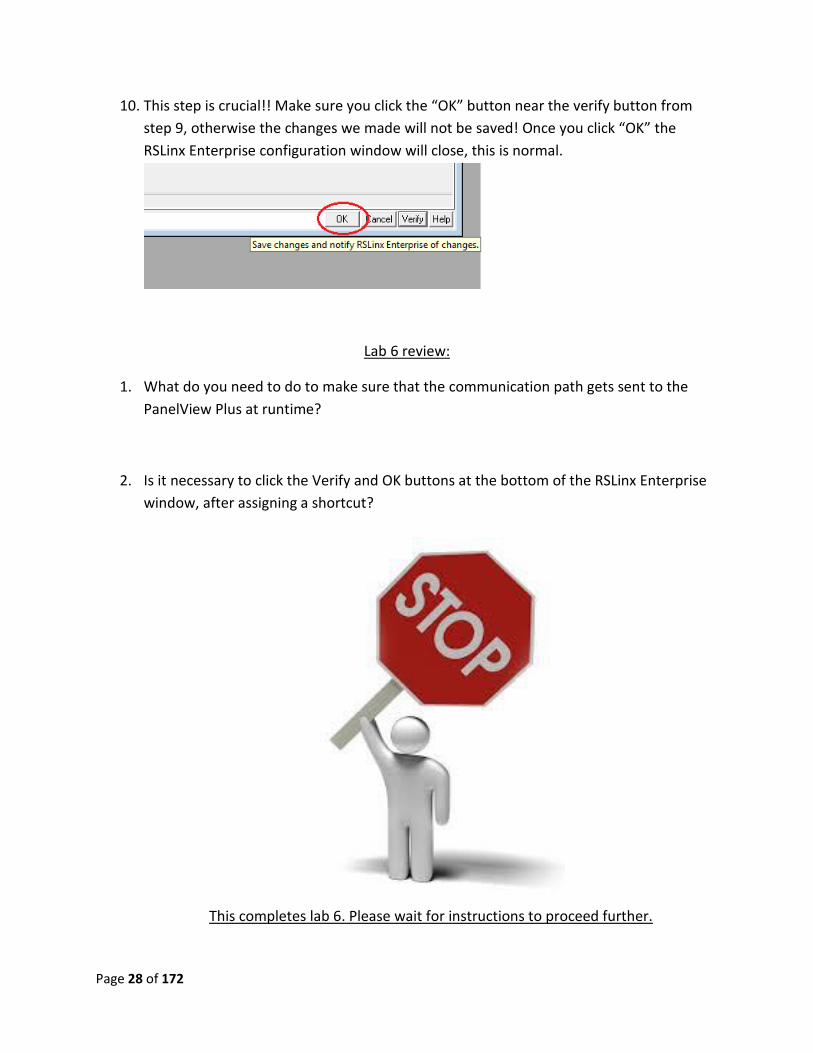
8. Once you click “Copy from Design to Runtime” from step 7, you will get a confirmation
message stating the changes you have made. Click “Yes” on the subsequent message.
9. The next thing we need to do, just for good measure is to verify the changes we have
made by clicking the “Verify” button show below. This shows us our current
communication path. Click “Close” on the “shortcut Verifier” window.
Page 28 of 172
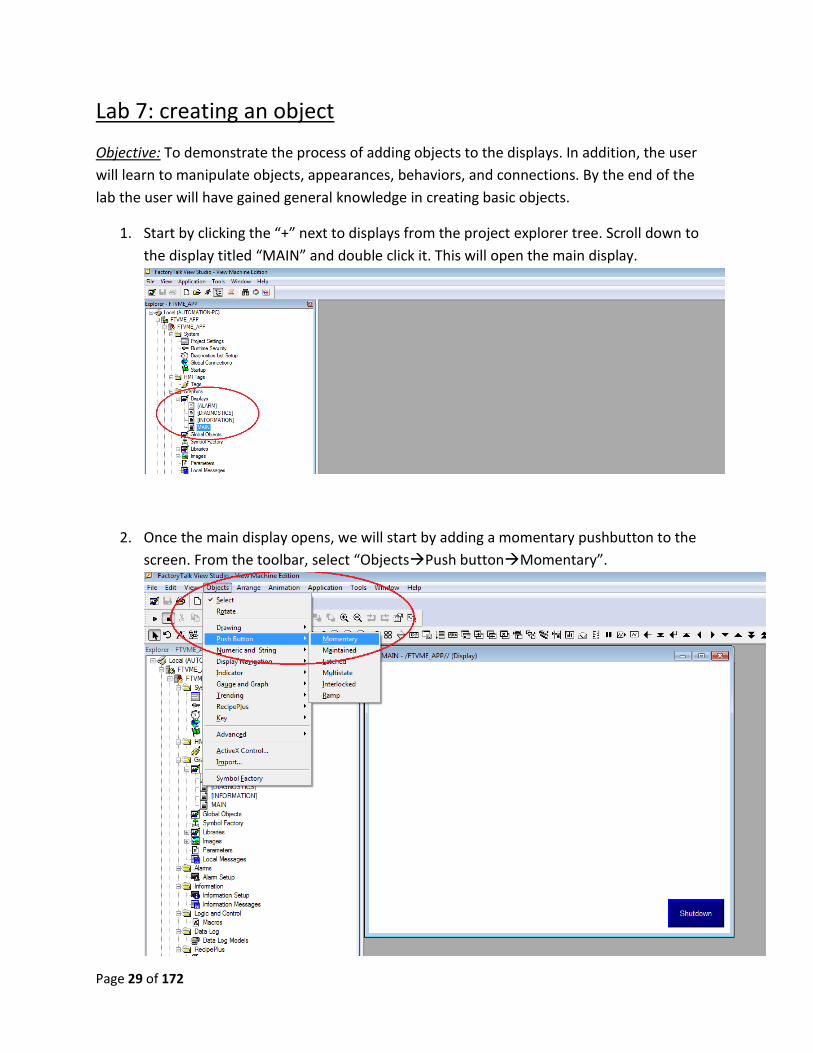
10. This step is crucial!! Make sure you click the “OK” button near the verify button from
step 9, otherwise the changes we made will not be saved! Once you click “OK” the
RSLinx Enterprise configuration window will close, this is normal.
Lab 6 review:
1. What do you need to do to make sure that the communication path gets sent to the
PanelView Plus at runtime?
2. Is it necessary to click the Verify and OK buttons at the bottom of the RSLinx Enterprise
window, after assigning a shortcut?
This completes lab 6. Please wait for instructions to proceed further.
Page 29 of 172
Lab 7: creating an object
Objective: To demonstrate the process of adding objects to the displays. In addition, the user
will learn to manipulate objects, appearances, behaviors, and connections. By the end of the
lab the user will have gained general knowledge in creating basic objects.
1. Start by clicking the “+” next to displays from the project explorer tree. Scroll down to
the display titled “MAIN” and double click it. This will open the main display.
2. Once the main display opens, we will start by adding a momentary pushbutton to the
screen. From the toolbar, select “ObjectsPush buttonMomentary”.
Page 30 of 172
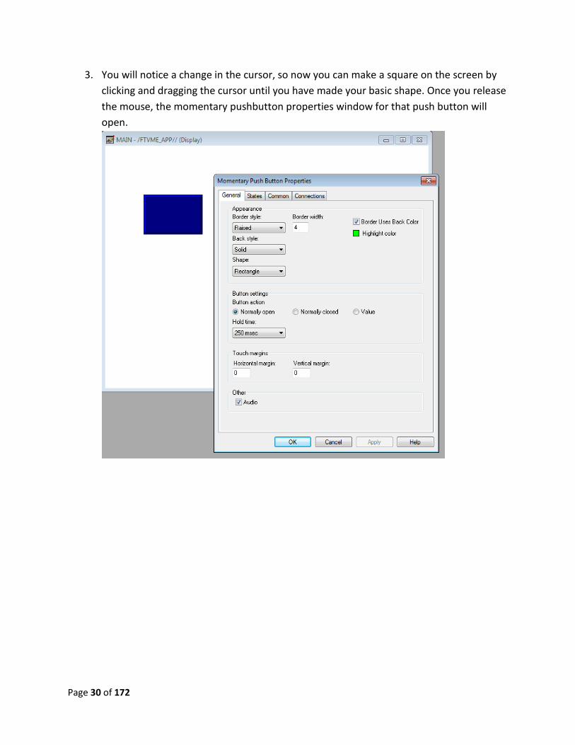
3. You will notice a change in the cursor, so now you can make a square on the screen by
clicking and dragging the cursor until you have made your basic shape. Once you release
the mouse, the momentary pushbutton properties window for that push button will
open.
Page 31 of 172
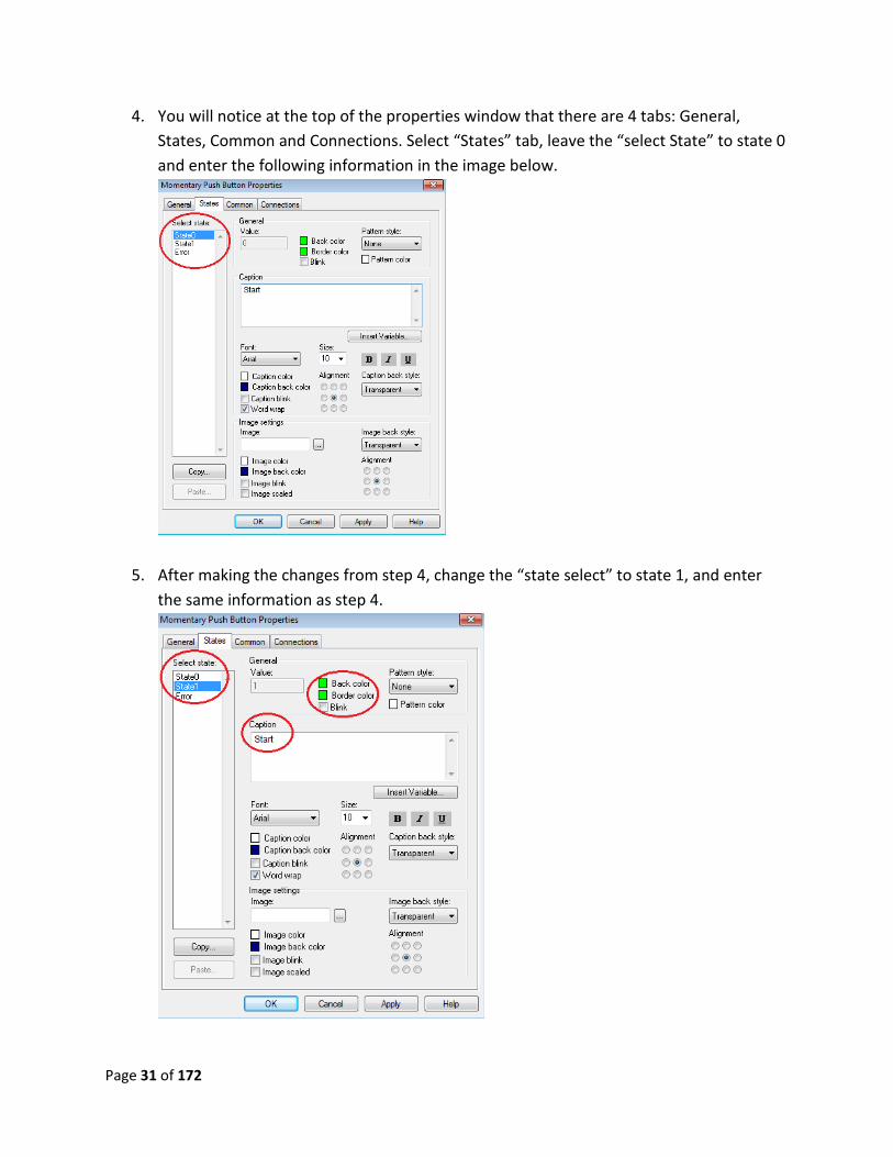
4. You will notice at the top of the properties window that there are 4 tabs: General,
States, Common and Connections. Select “States” tab, leave the “select State” to state 0
and enter the following information in the image below.
5. After making the changes from step 4, change the “state select” to state 1, and enter
the same information as step 4.
Page 32 of 172
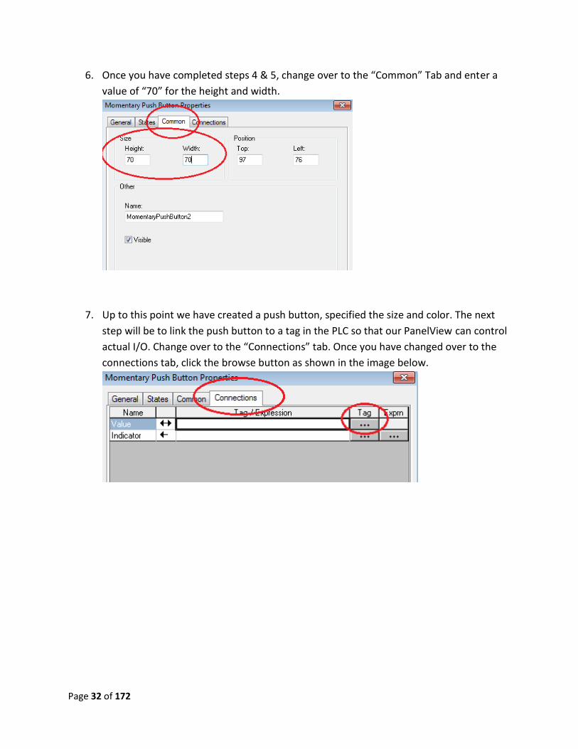
6. Once you have completed steps 4 & 5, change over to the “Common” Tab and enter a
value of “70” for the height and width.
7. Up to this point we have created a push button, specified the size and color. The next
step will be to link the push button to a tag in the PLC so that our PanelView can control
actual I/O. Change over to the “Connections” tab. Once you have changed over to the
connections tab, click the browse button as shown in the image below.
Page 33 of 172
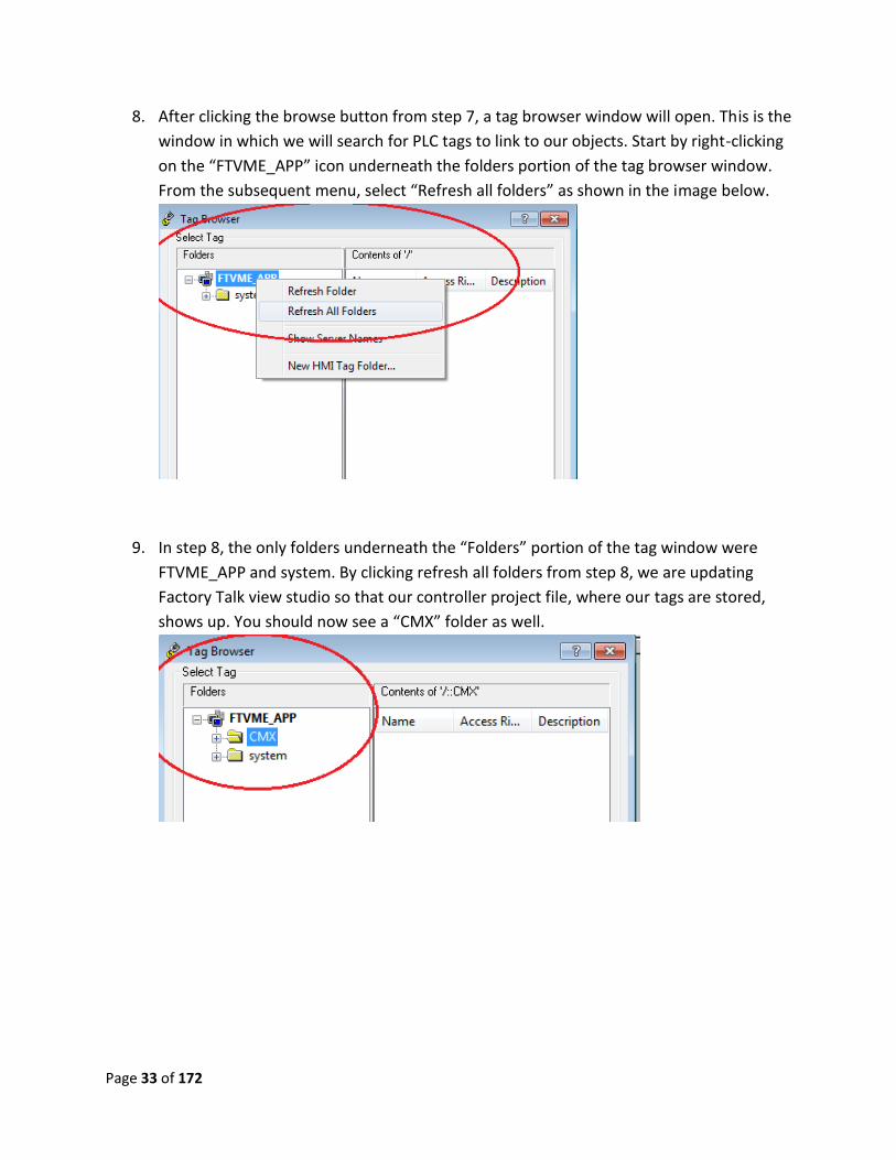
8. After clicking the browse button from step 7, a tag browser window will open. This is the
window in which we will search for PLC tags to link to our objects. Start by right-clicking
on the “FTVME_APP” icon underneath the folders portion of the tag browser window.
From the subsequent menu, select “Refresh all folders” as shown in the image below.
9. In step 8, the only folders underneath the “Folders” portion of the tag window were
FTVME_APP and system. By clicking refresh all folders from step 8, we are updating
Factory Talk view studio so that our controller project file, where our tags are stored,
shows up. You should now see a “CMX” folder as well.
Page 34 of 172
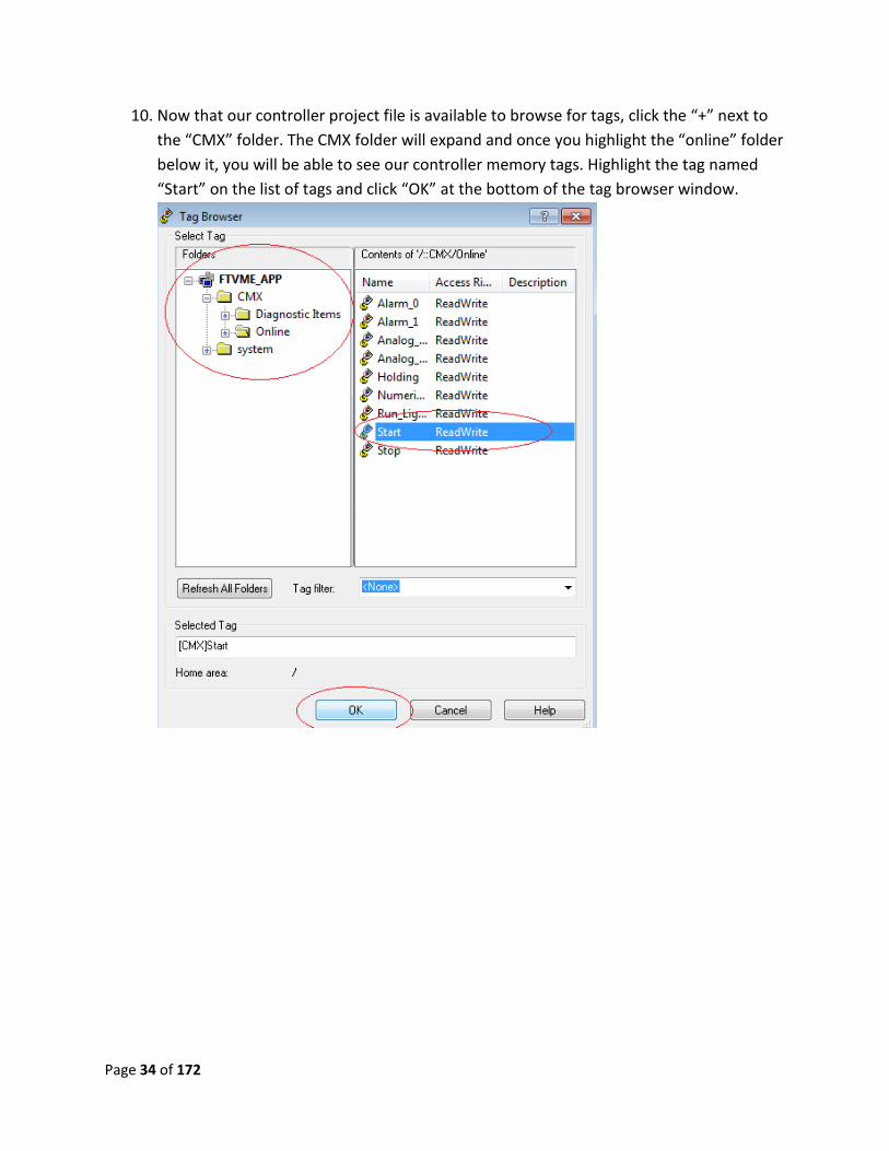
10. Now that our controller project file is available to browse for tags, click the “+” next to
the “CMX” folder. The CMX folder will expand and once you highlight the “online” folder
below it, you will be able to see our controller memory tags. Highlight the tag named
“Start” on the list of tags and click “OK” at the bottom of the tag browser window.
Page 35 of 172
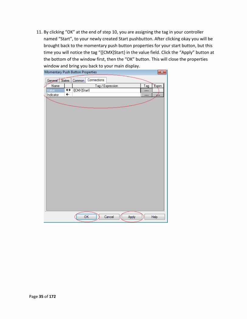
11. By clicking “OK” at the end of step 10, you are assigning the tag in your controller
named “Start”, to your newly created Start pushbutton. After clicking okay you will be
brought back to the momentary push button properties for your start button, but this
time you will notice the tag “{[CMX]Start} in the value field. Click the “Apply” button at
the bottom of the window first, then the “OK” button. This will close the properties
window and bring you back to your main display.
Page 36 of 172
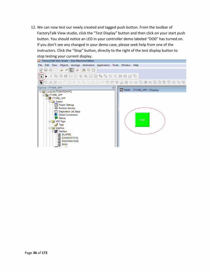
12. We can now test our newly created and tagged push button. From the toolbar of
FactoryTalk View studio, click the “Test Display” button and then click on your start push
button. You should notice an LED in your controller demo labeled “DO0” has turned on.
If you don’t see any changed in your demo case, please seek help from one of the
instructors. Click the “Stop” button, directly to the right of the test display button to
stop testing your current display.
Page 37 of 172
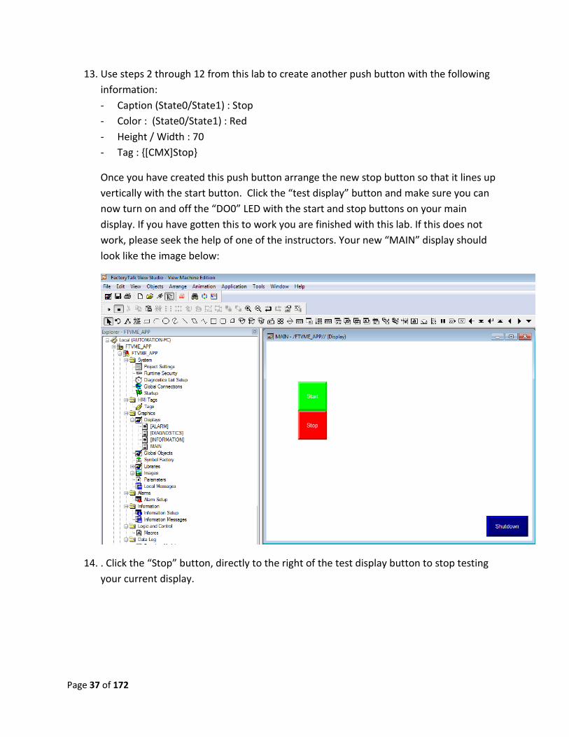
13. Use steps 2 through 12 from this lab to create another push button with the following
information:
- Caption (State0/State1) : Stop
- Color : (State0/State1) : Red
- Height / Width : 70
- Tag : {[CMX]Stop}
Once you have created this push button arrange the new stop button so that it lines up
vertically with the start button. Click the “test display” button and make sure you can
now turn on and off the “DO0” LED with the start and stop buttons on your main
display. If you have gotten this to work you are finished with this lab. If this does not
work, please seek the help of one of the instructors. Your new “MAIN” display should
look like the image below:
14. . Click the “Stop” button, directly to the right of the test display button to stop testing
your current display.
Page 38 of 172
Lab 7 Review
1. When referring to {[CMX]Start}, what does CMX stand for? What is start?
2. If you are in the browse tag window and can’t see the tag you are looking for, what are
the steps you would take to refresh the folder?
3. How can you test the current display you have open to make sure your PLC / PanelView
connection is up and running?
This completes lab 7. Please wait for instructions to proceed further.
Page 39 of 172
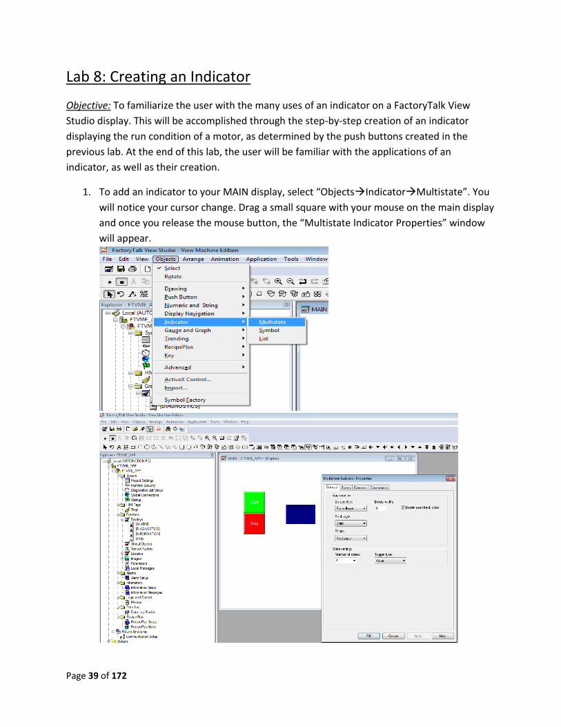
Lab 8: Creating an Indicator
Objective: To familiarize the user with the many uses of an indicator on a FactoryTalk View
Studio display. This will be accomplished through the step-by-step creation of an indicator
displaying the run condition of a motor, as determined by the push buttons created in the
previous lab. At the end of this lab, the user will be familiar with the applications of an
indicator, as well as their creation.
1. To add an indicator to your MAIN display, select “ObjectsIndicatorMultistate”. You
will notice your cursor change. Drag a small square with your mouse on the main display
and once you release the mouse button, the “Multistate Indicator Properties” window
will appear.
Page 40 of 172
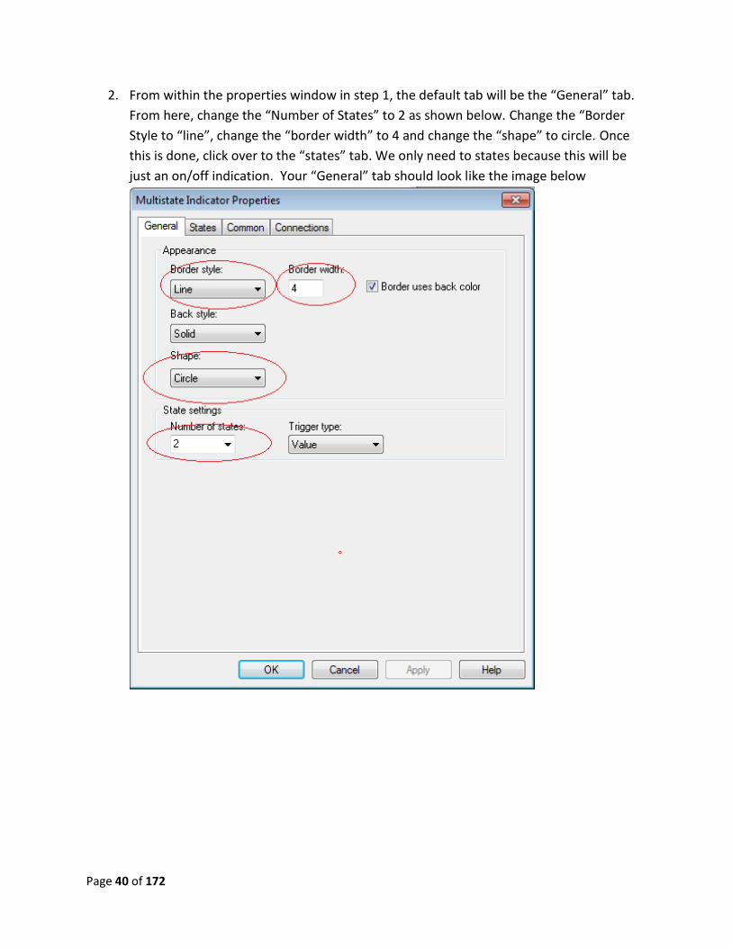
2. From within the properties window in step 1, the default tab will be the “General” tab.
From here, change the “Number of States” to 2 as shown below. Change the “Border
Style to “line”, change the “border width” to 4 and change the “shape” to circle. Once
this is done, click over to the “states” tab. We only need to states because this will be
just an on/off indication. Your “General” tab should look like the image below
Page 41 of 172
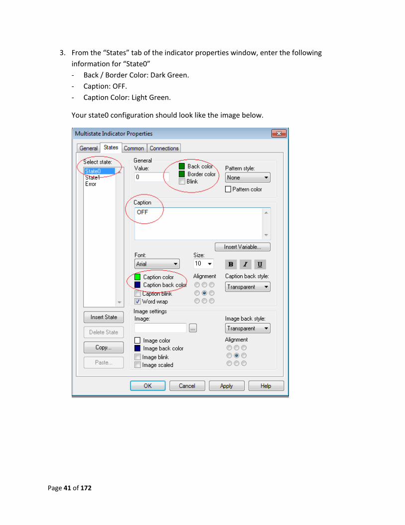
3. From the “States” tab of the indicator properties window, enter the following
information for “State0”
- Back / Border Color: Dark Green.
- Caption: OFF.
- Caption Color: Light Green.
Your state0 configuration should look like the image below.
Page 42 of 172
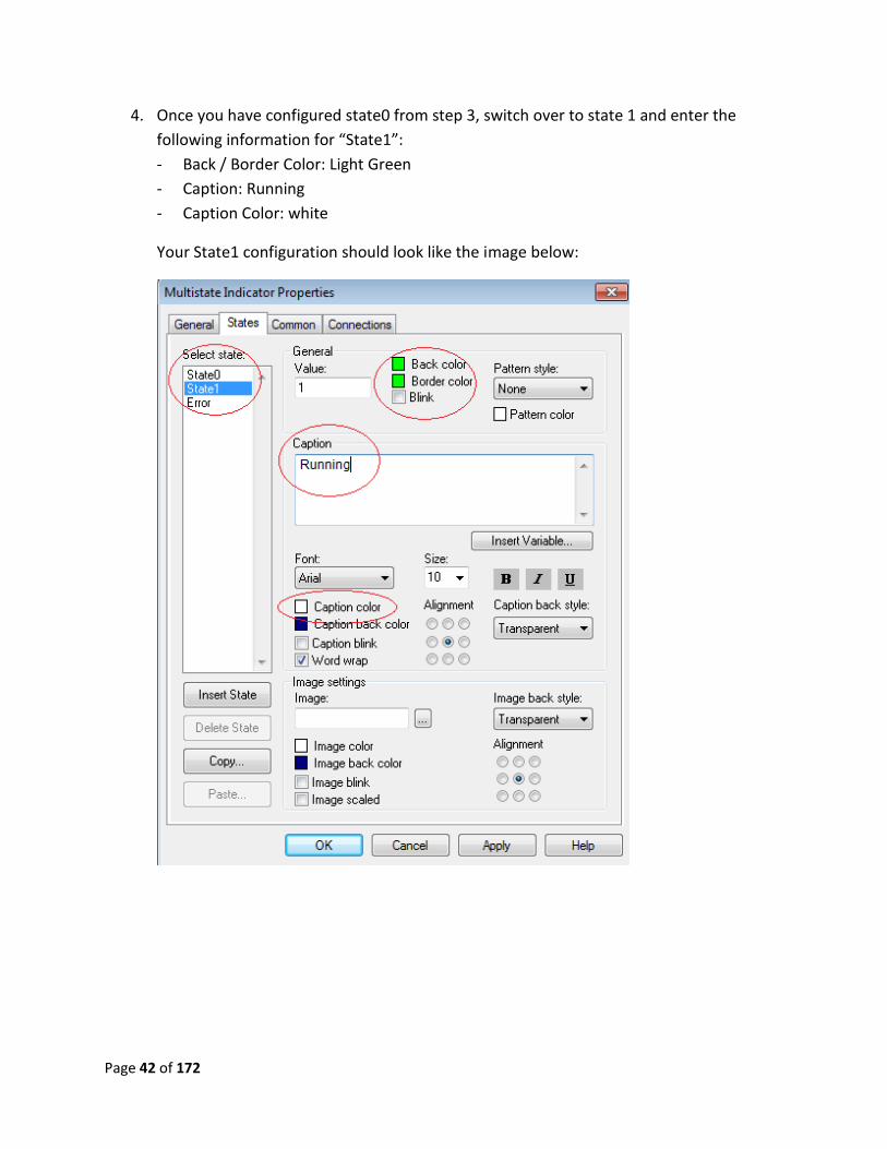
4. Once you have configured state0 from step 3, switch over to state 1 and enter the
following information for “State1”:
- Back / Border Color: Light Green
- Caption: Running
- Caption Color: white
Your State1 configuration should look like the image below:
Page 43 of 172
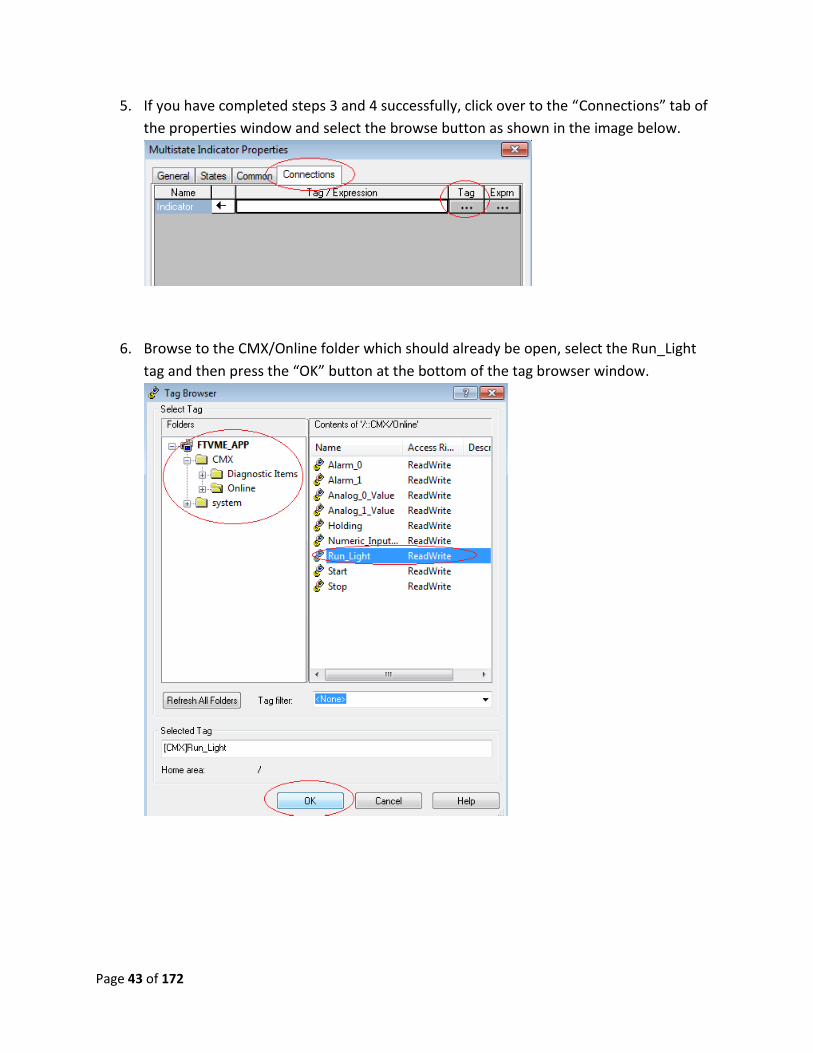
5. If you have completed steps 3 and 4 successfully, click over to the “Connections” tab of
the properties window and select the browse button as shown in the image below.
6. Browse to the CMX/Online folder which should already be open, select the Run_Light
tag and then press the “OK” button at the bottom of the tag browser window.
Page 44 of 172
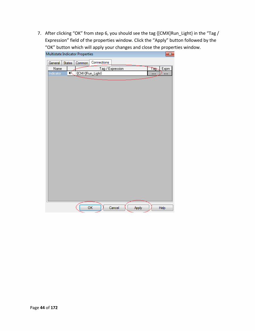
7. After clicking “OK” from step 6, you should see the tag {[CMX]Run_Light} in the “Tag /
Expression” field of the properties window. Click the “Apply” button followed by the
“OK” button which will apply your changes and close the properties window.
Page 45 of 172
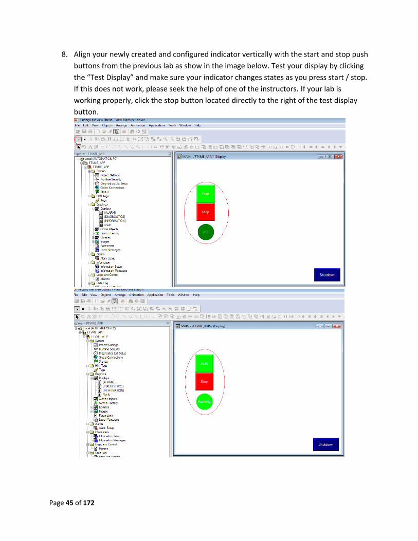
8. Align your newly created and configured indicator vertically with the start and stop push
buttons from the previous lab as show in the image below. Test your display by clicking
the “Test Display” and make sure your indicator changes states as you press start / stop.
If this does not work, please seek the help of one of the instructors. If your lab is
working properly, click the stop button located directly to the right of the test display
button.

Page 46 of 172
Lab 8 review
1. In the Multistate properties window, what tab lets you change the number of states?
2. Can you place a different image on different states?
3. How many different states are possible?
This completes lab 8. Please wait for instructions to proceed further.
Page 47 of 172
Lab 9: Numeric Data Display
Objective: To introduce the user to the basic manipulation of a numeric data display object on a
PanelView Plus display. To meet this goal, this exercise will cover step-by-step, creation,
configuration and implementation of the numeric display. By the end of this lab, the user
should be well-versed in displaying these data types, as well as determining when its use is
advantageous.
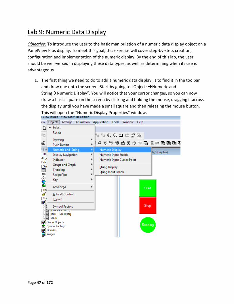
1. The first thing we need to do to add a numeric data display, is to find it in the toolbar
and draw one onto the screen. Start by going to “ObjectsNumeric and
StringNumeric Display”. You will notice that your cursor changes, so you can now
draw a basic square on the screen by clicking and holding the mouse, dragging it across
the display until you have made a small square and then releasing the mouse button.
This will open the “Numeric Display Properties” window.
Page 48 of 172
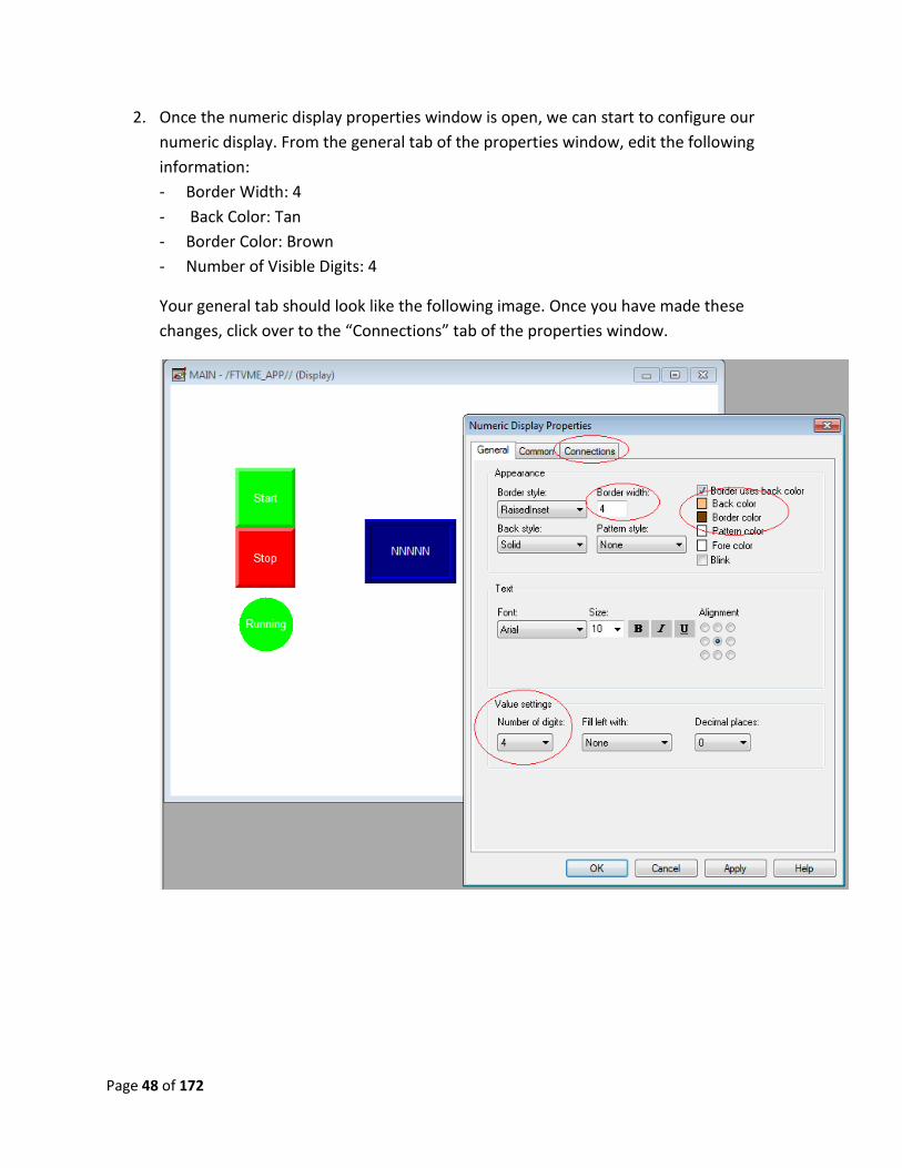
2. Once the numeric display properties window is open, we can start to configure our
numeric display. From the general tab of the properties window, edit the following
information:
- Border Width: 4
- Back Color: Tan
- Border Color: Brown
- Number of Visible Digits: 4
Your general tab should look like the following image. Once you have made these
changes, click over to the “Connections” tab of the properties window.
Page 49 of 172
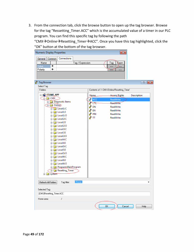
3. From the connection tab, click the browse button to open up the tag browser. Browse
for the tag “Ressetting_Timer.ACC” which is the accumulated value of a timer in our PLC
program. You can find this specific tag by following the path
“CMXOnlineResetting_TimerACC”. Once you have this tag highlighted, click the
“OK” button at the bottom of the tag browser.
Page 50 of 172
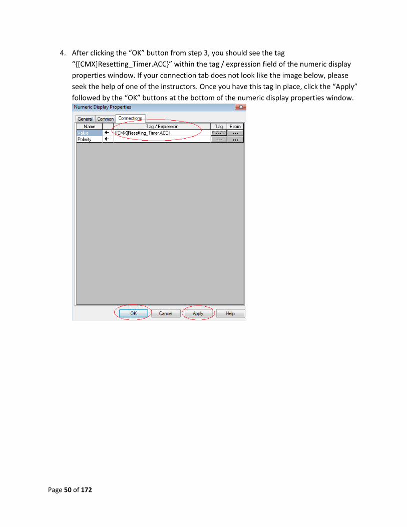
4. After clicking the “OK” button from step 3, you should see the tag
“{[CMX]Resetting_Timer.ACC}” within the tag / expression field of the numeric display
properties window. If your connection tab does not look like the image below, please
seek the help of one of the instructors. Once you have this tag in place, click the “Apply”
followed by the “OK” buttons at the bottom of the numeric display properties window.
Page 51 of 172
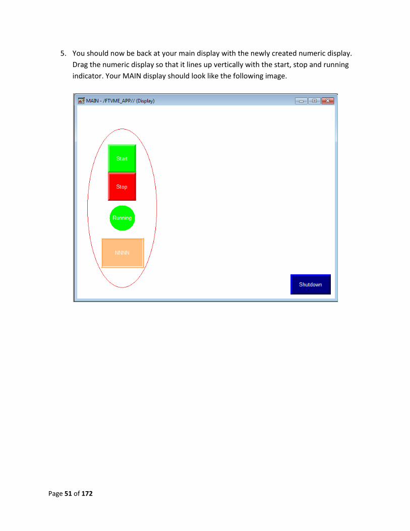
5. You should now be back at your main display with the newly created numeric display.
Drag the numeric display so that it lines up vertically with the start, stop and running
indicator. Your MAIN display should look like the following image.
Page 52 of 172
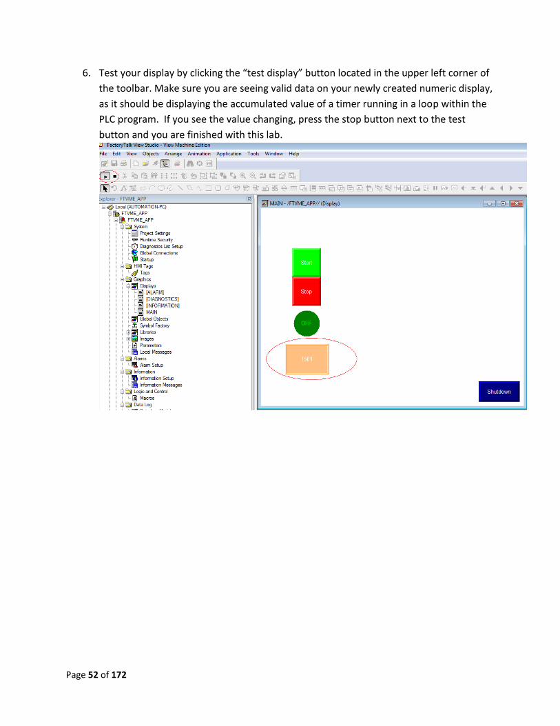
6. Test your display by clicking the “test display” button located in the upper left corner of
the toolbar. Make sure you are seeing valid data on your newly created numeric display,
as it should be displaying the accumulated value of a timer running in a loop within the
PLC program. If you see the value changing, press the stop button next to the test
button and you are finished with this lab.
Page 53 of 172
Lab 9 Review
1. Within the properties window, which tab allows you to change the number of visible
digits?
2. Where is the tag update rate located?
3. How would you display a decimal value to the hundredths place?
This completes lab 9. Please wait for instructions to proceed further.
Page 54 of 172
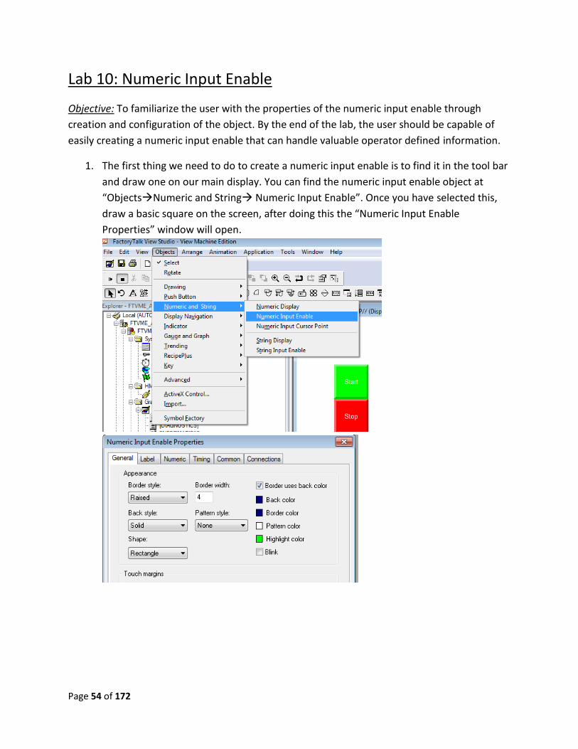
Lab 10: Numeric Input Enable
Objective: To familiarize the user with the properties of the numeric input enable through
creation and configuration of the object. By the end of the lab, the user should be capable of
easily creating a numeric input enable that can handle valuable operator defined information.
1. The first thing we need to do to create a numeric input enable is to find it in the tool bar
and draw one on our main display. You can find the numeric input enable object at
“ObjectsNumeric and String Numeric Input Enable”. Once you have selected this,
draw a basic square on the screen, after doing this the “Numeric Input Enable
Properties” window will open.
Page 55 of 172
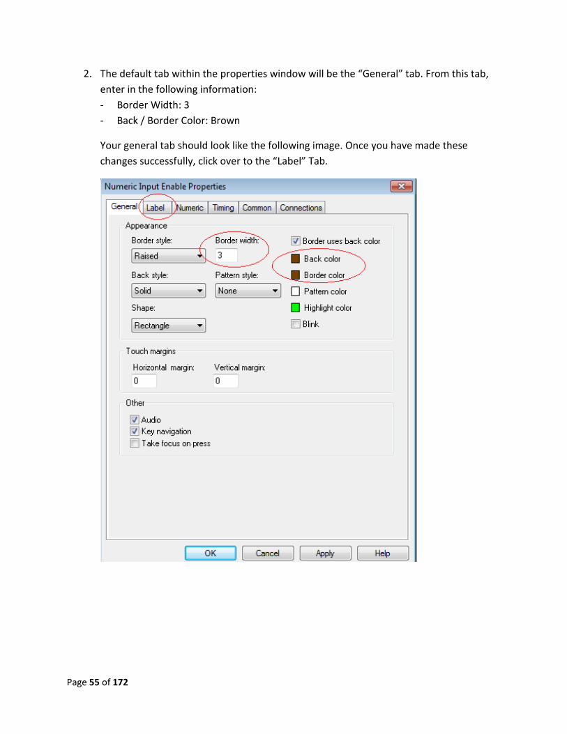
2. The default tab within the properties window will be the “General” tab. From this tab,
enter in the following information:
- Border Width: 3
- Back / Border Color: Brown
Your general tab should look like the following image. Once you have made these
changes successfully, click over to the “Label” Tab.
Page 56 of 172
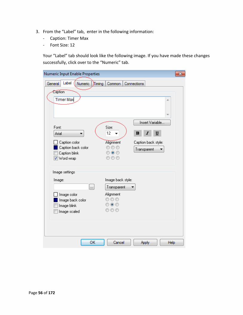
3. From the “Label” tab, enter in the following information:
- Caption: Timer Max
- Font Size: 12
Your “Label” tab should look like the following image. If you have made these changes
successfully, click over to the “Numeric” tab.
Page 57 of 172
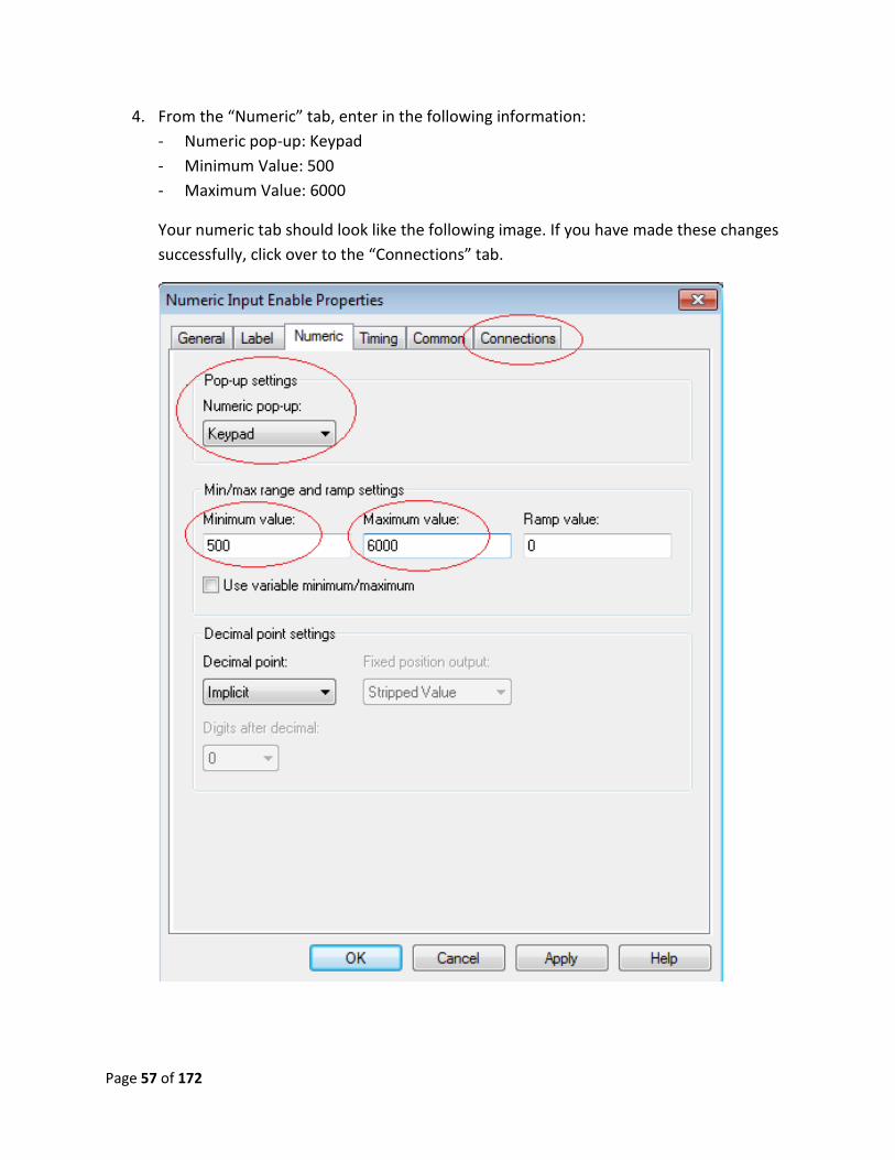
4. From the “Numeric” tab, enter in the following information:
- Numeric pop-up: Keypad
- Minimum Value: 500
- Maximum Value: 6000
Your numeric tab should look like the following image. If you have made these changes
successfully, click over to the “Connections” tab.
Page 58 of 172
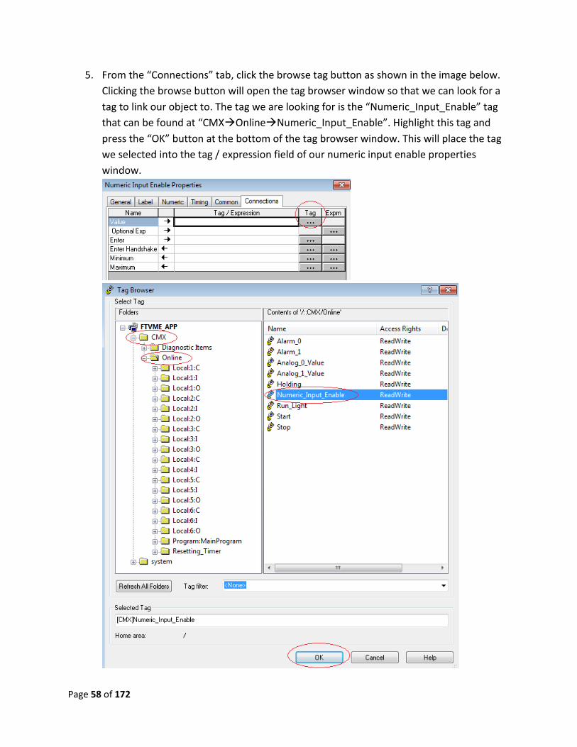
5. From the “Connections” tab, click the browse tag button as shown in the image below.
Clicking the browse button will open the tag browser window so that we can look for a
tag to link our object to. The tag we are looking for is the “Numeric_Input_Enable” tag
that can be found at “CMXOnlineNumeric_Input_Enable”. Highlight this tag and
press the “OK” button at the bottom of the tag browser window. This will place the tag
we selected into the tag / expression field of our numeric input enable properties
window.
Page 59 of 172
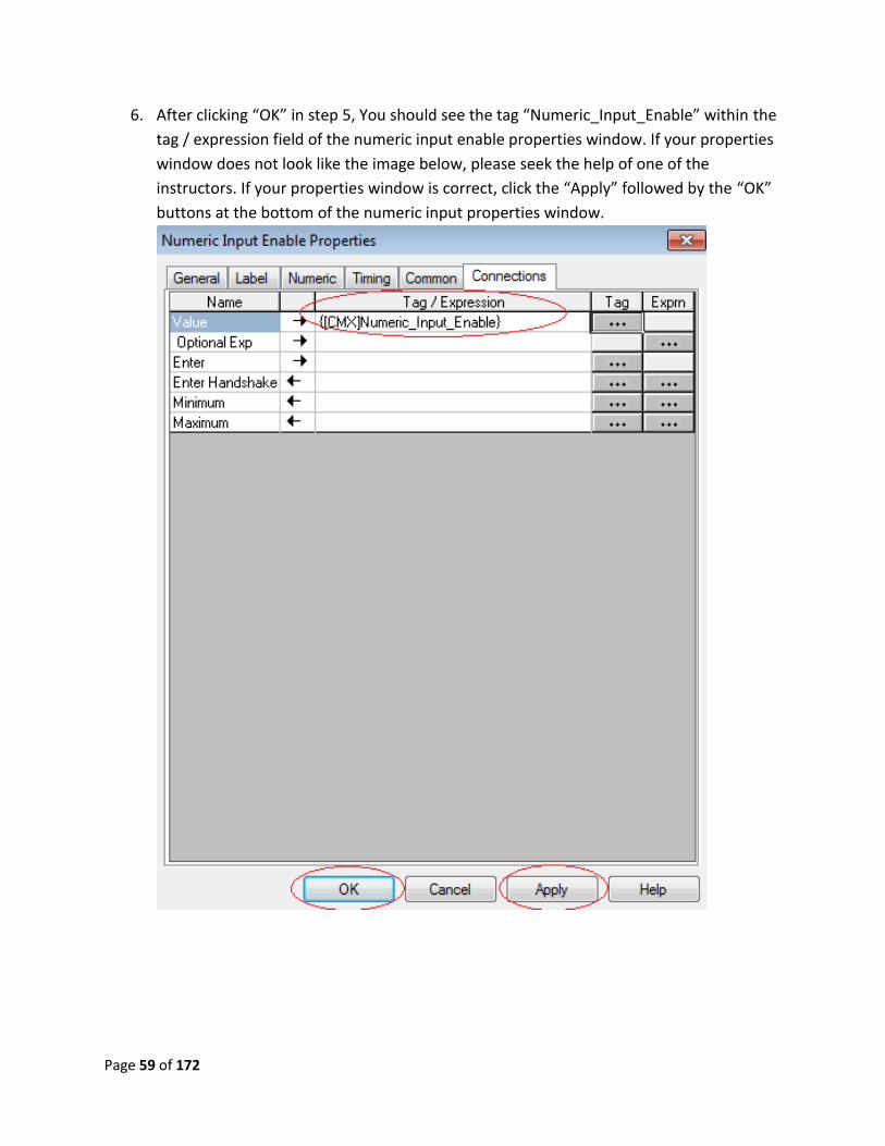
6. After clicking “OK” in step 5, You should see the tag “Numeric_Input_Enable” within the
tag / expression field of the numeric input enable properties window. If your properties
window does not look like the image below, please seek the help of one of the
instructors. If your properties window is correct, click the “Apply” followed by the “OK”
buttons at the bottom of the numeric input properties window.
Page 60 of 172
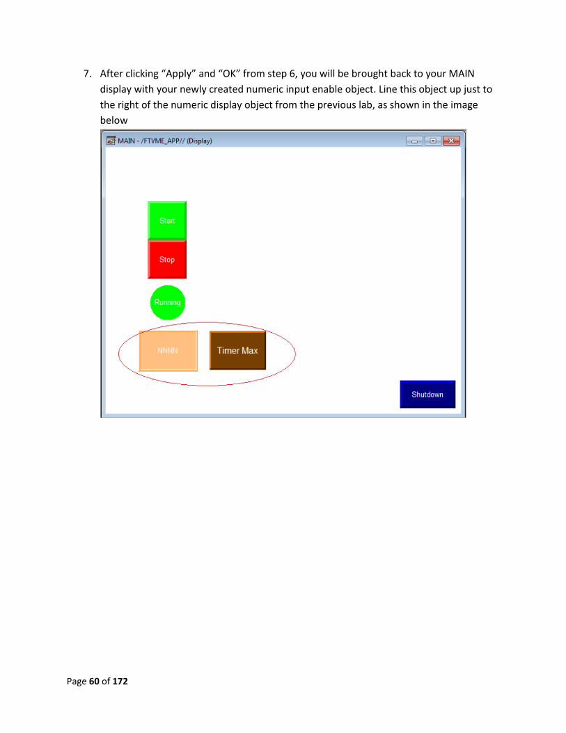
7. After clicking “Apply” and “OK” from step 6, you will be brought back to your MAIN
display with your newly created numeric input enable object. Line this object up just to
the right of the numeric display object from the previous lab, as shown in the image
below
Page 61 of 172
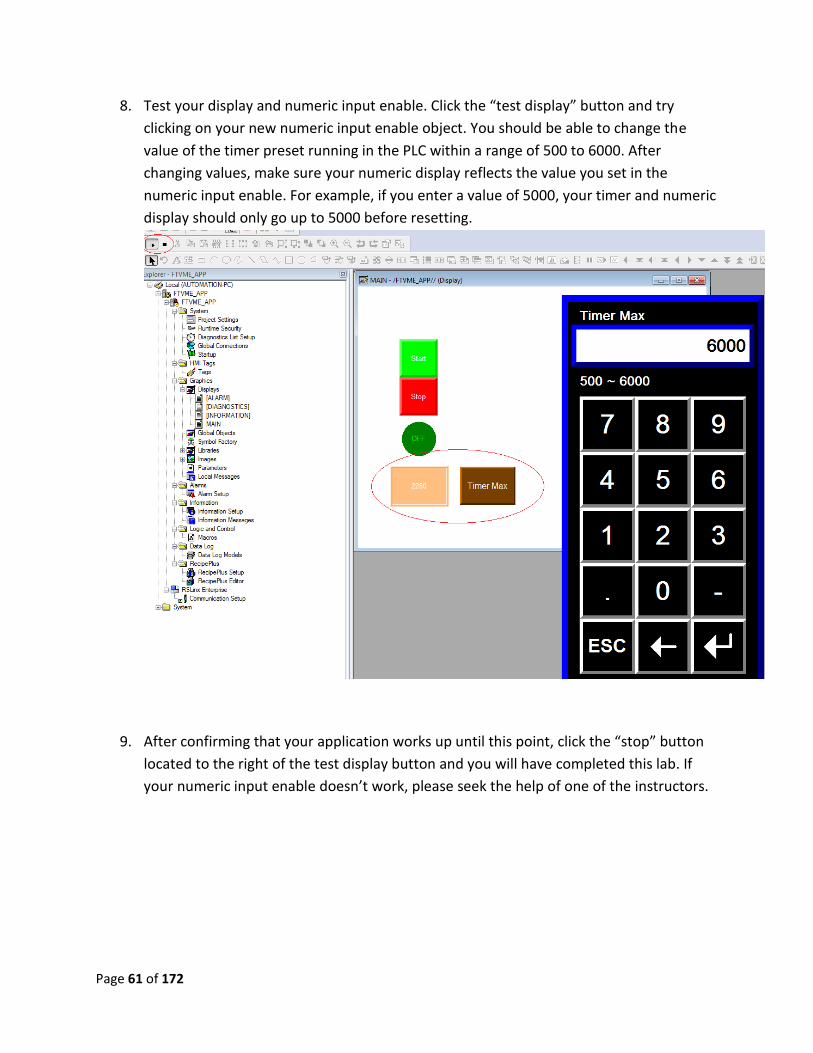
8. Test your display and numeric input enable. Click the “test display” button and try
clicking on your new numeric input enable object. You should be able to change the
value of the timer preset running in the PLC within a range of 500 to 6000. After
changing values, make sure your numeric display reflects the value you set in the
numeric input enable. For example, if you enter a value of 5000, your timer and numeric
display should only go up to 5000 before resetting.
9. After confirming that your application works up until this point, click the “stop” button
located to the right of the test display button and you will have completed this lab. If
your numeric input enable doesn’t work, please seek the help of one of the instructors.
Page 62 of 172
Lab 10 Review:
1. In the numeric input enable properties window, what tab can you set the minimum and
maximum values?
2. If you set the numeric pop-up to scratch pad, what must be attached to the PanelView
in order to enter values?
3. What happens if you enter the value of 450 on the keypad of the numeric input enable?
This completes lab 10. Please wait for instructions to proceed further.
Page 63 of 172
Lab 11: Saving / Downloading an application
Objective: To introduce the user to the concepts of saving and downloading PanelView Plus
programs (.MER files) as well as basic PanelView Plus communications. By the end of this lab,
the user will be able to create the runtime file on their local PC, as well as downloading that file
to the PanelView.
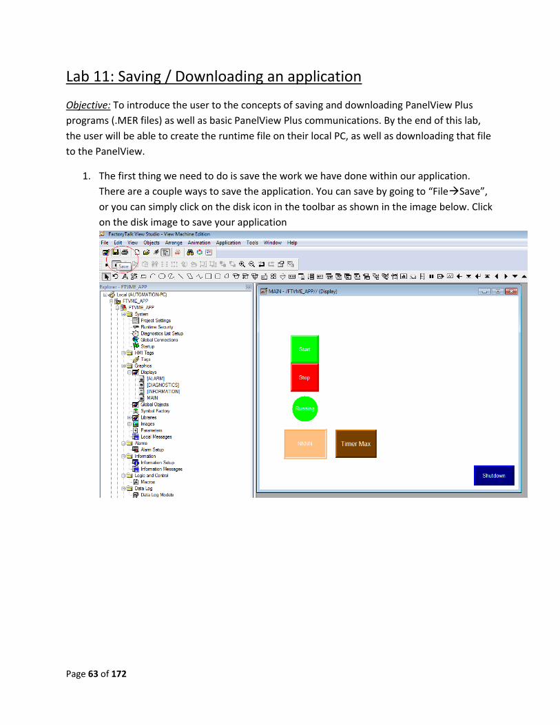
1. The first thing we need to do is save the work we have done within our application.
There are a couple ways to save the application. You can save by going to “FileSave”,
or you can simply click on the disk icon in the toolbar as shown in the image below. Click
on the disk image to save your application
Page 64 of 172
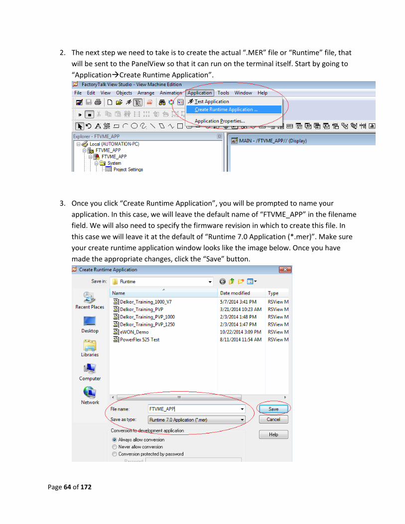
2. The next step we need to take is to create the actual “.MER” file or “Runtime” file, that
will be sent to the PanelView so that it can run on the terminal itself. Start by going to
“ApplicationCreate Runtime Application”.
3. Once you click “Create Runtime Application”, you will be prompted to name your
application. In this case, we will leave the default name of “FTVME_APP” in the filename
field. We will also need to specify the firmware revision in which to create this file. In
this case we will leave it at the default of “Runtime 7.0 Application (*.mer)”. Make sure
your create runtime application window looks like the image below. Once you have
made the appropriate changes, click the “Save” button.
Page 65 of 172
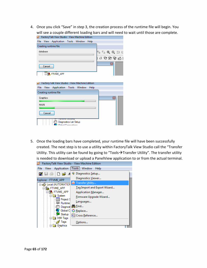
4. Once you click “Save” in step 3, the creation process of the runtime file will begin. You
will see a couple different loading bars and will need to wait until those are complete.
5. Once the loading bars have completed, your runtime file will have been successfully
created. The next step is to use a utility within FactoryTalk View Studio call the “Transfer
Utility. This utility can be found by going to “ToolsTransfer Utility”. The transfer utility
is needed to download or upload a PanelView application to or from the actual terminal.
Page 66 of 172
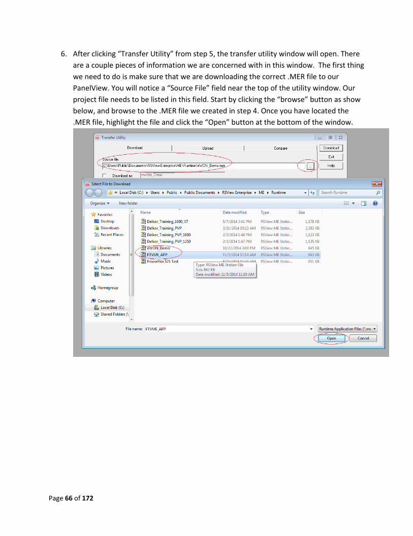
6. After clicking “Transfer Utility” from step 5, the transfer utility window will open. There
are a couple pieces of information we are concerned with in this window. The first thing
we need to do is make sure that we are downloading the correct .MER file to our
PanelView. You will notice a “Source File” field near the top of the utility window. Our
project file needs to be listed in this field. Start by clicking the “browse” button as show
below, and browse to the .MER file we created in step 4. Once you have located the
.MER file, highlight the file and click the “Open” button at the bottom of the window.
Page 67 of 172
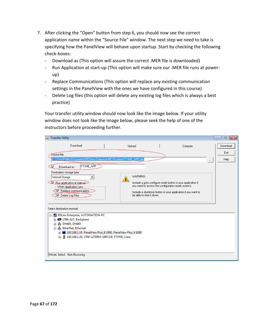
7. After clicking the “Open” button from step 6, you should now see the correct
application name within the “Source File” window. The next step we need to take is
specifying how the PanelView will behave upon startup. Start by checking the following
check-boxes:
- Download as (This option will assure the correct .MER file is downloaded)
- Run Application at start-up (This option will make sure our .MER file runs at power-
up)
- Replace Communications (This option will replace any existing communication
settings in the PanelView with the ones we have configured in this course)
- Delete Log files (this option will delete any existing log files which is always a best
practice)
Your transfer utility window should now look like the image below. If your utility
window does not look like the image below, please seek the help of one of the
instructors before proceeding further.
Page 68 of 172
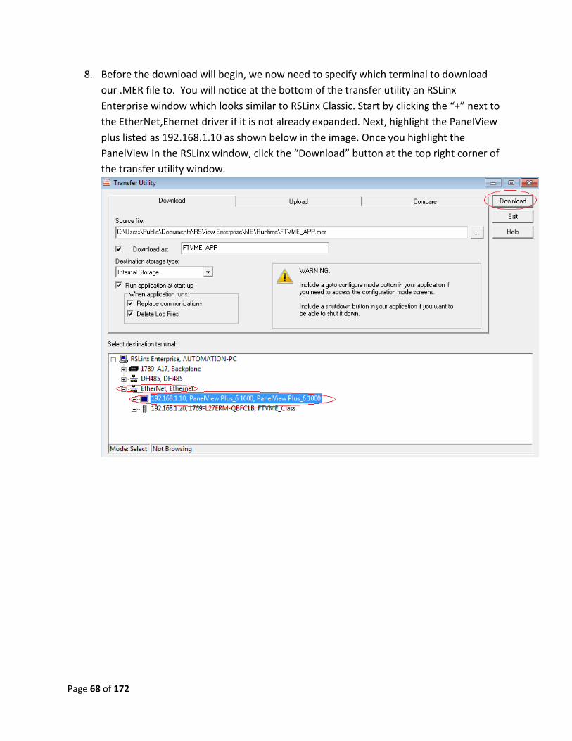
8. Before the download will begin, we now need to specify which terminal to download
our .MER file to. You will notice at the bottom of the transfer utility an RSLinx
Enterprise window which looks similar to RSLinx Classic. Start by clicking the “+” next to
the EtherNet,Ehernet driver if it is not already expanded. Next, highlight the PanelView
plus listed as 192.168.1.10 as shown below in the image. Once you highlight the
PanelView in the RSLinx window, click the “Download” button at the top right corner of
the transfer utility window.
Page 69 of 172
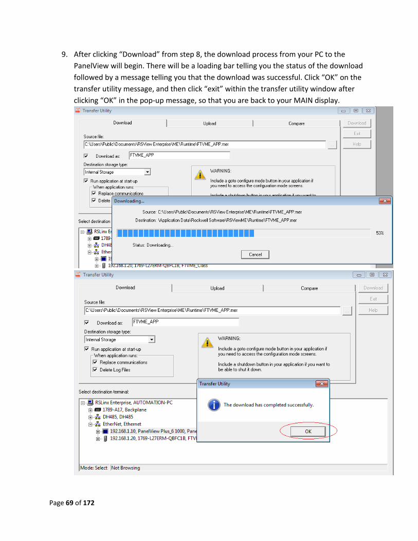
9. After clicking “Download” from step 8, the download process from your PC to the
PanelView will begin. There will be a loading bar telling you the status of the download
followed by a message telling you that the download was successful. Click “OK” on the
transfer utility message, and then click “exit” within the transfer utility window after
clicking “OK” in the pop-up message, so that you are back to your MAIN display.
Page 70 of 172
10. After the download process, you will notice that your PanelView reboots, and loads the
application we downloaded to it. Play around with the application running on your
PanelView and make sure everything works without errors. If everything works, you
have completed this lab. If you have any errors, please seek the help of one of the
instructors.
Lab 11 Review:
1. What does .MER stand for?
2. What does .MED stand for?
3. What happens at runtime if you don’t check the box “Run application at start up”?
This now completes lab 11. Please wait for instructions to proceed further.
Page 71 of 172
Lab 12: Creating a bar graph
Objective: To familiarize the user with the concept and implementation of bar graphs in a
PanelView Plus application. This lab will walk the user through the complete process of creating
and configuring a bar graph, as well as empower the user to apply this to his/her specific needs.
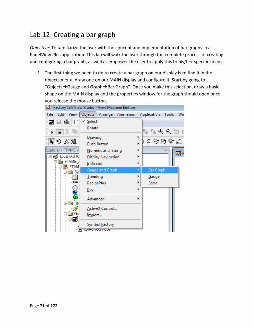
1. The first thing we need to do to create a bar graph on our display is to find it in the
objects menu, draw one on our MAIN display and configure it. Start by going to
“ObjectsGauge and GraphBar Graph”. Once you make this selection, draw a basic
shape on the MAIN display and the properties window for the graph should open once
you release the mouse button.
Page 72 of 172
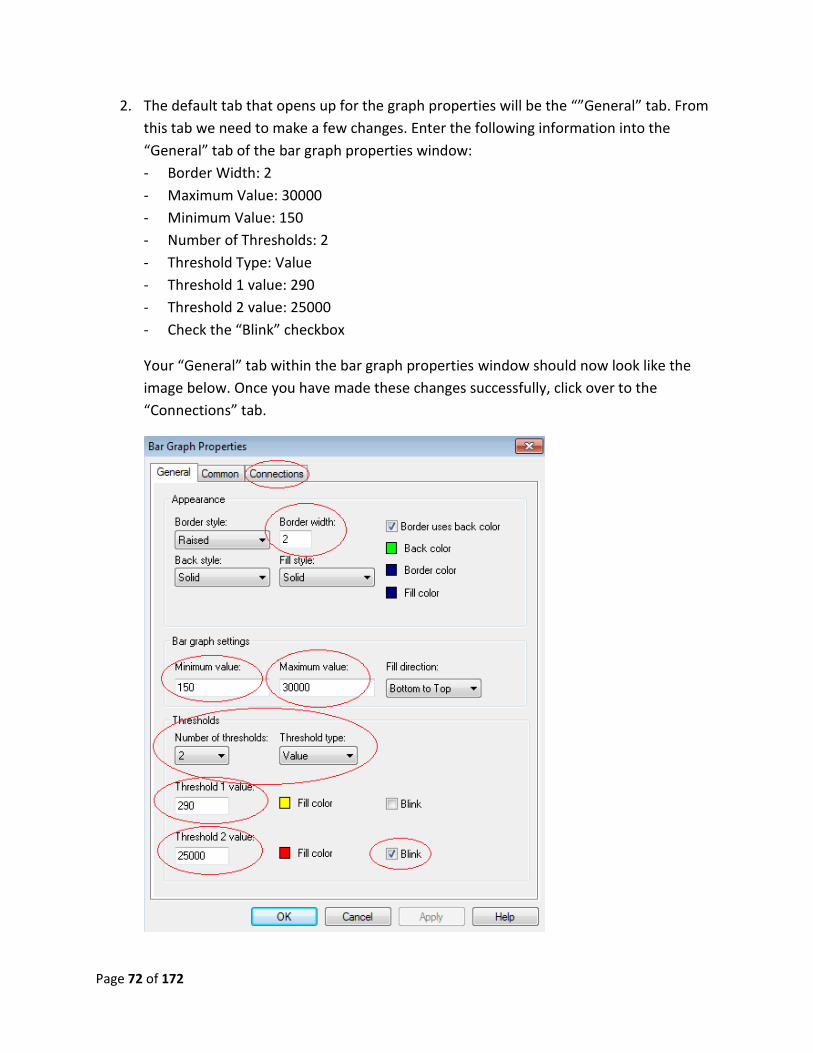
2. The default tab that opens up for the graph properties will be the “”General” tab. From
this tab we need to make a few changes. Enter the following information into the
“General” tab of the bar graph properties window:
- Border Width: 2
- Maximum Value: 30000
- Minimum Value: 150
- Number of Thresholds: 2
- Threshold Type: Value
- Threshold 1 value: 290
- Threshold 2 value: 25000
- Check the “Blink” checkbox
Your “General” tab within the bar graph properties window should now look like the
image below. Once you have made these changes successfully, click over to the
“Connections” tab.
Page 73 of 172
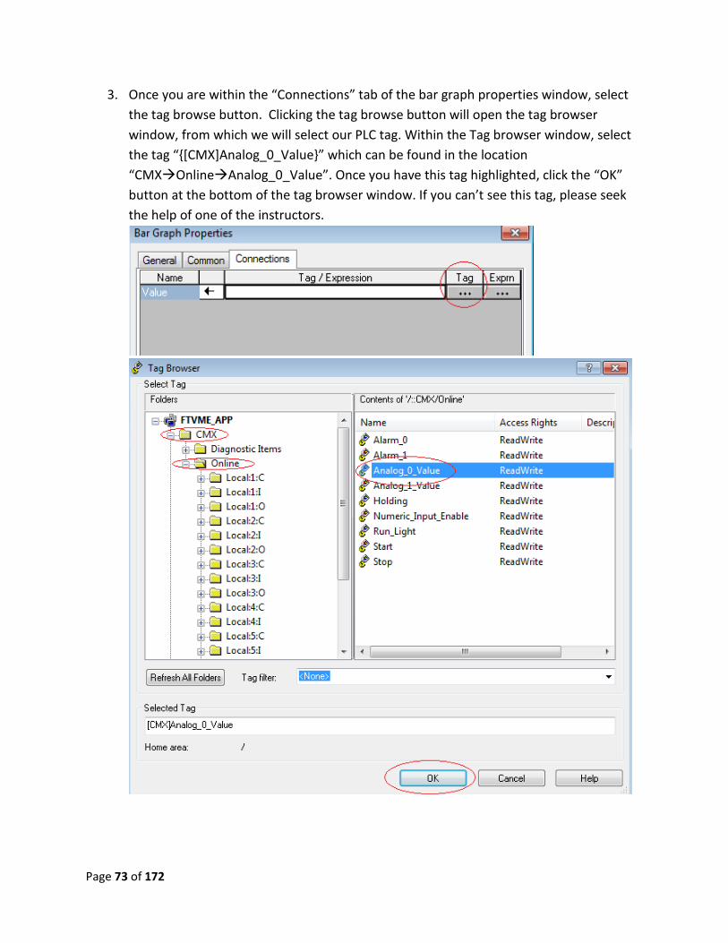
3. Once you are within the “Connections” tab of the bar graph properties window, select
the tag browse button. Clicking the tag browse button will open the tag browser
window, from which we will select our PLC tag. Within the Tag browser window, select
the tag “{[CMX]Analog_0_Value}” which can be found in the location
“CMXOnlineAnalog_0_Value”. Once you have this tag highlighted, click the “OK”
button at the bottom of the tag browser window. If you can’t see this tag, please seek
the help of one of the instructors.
Page 74 of 172
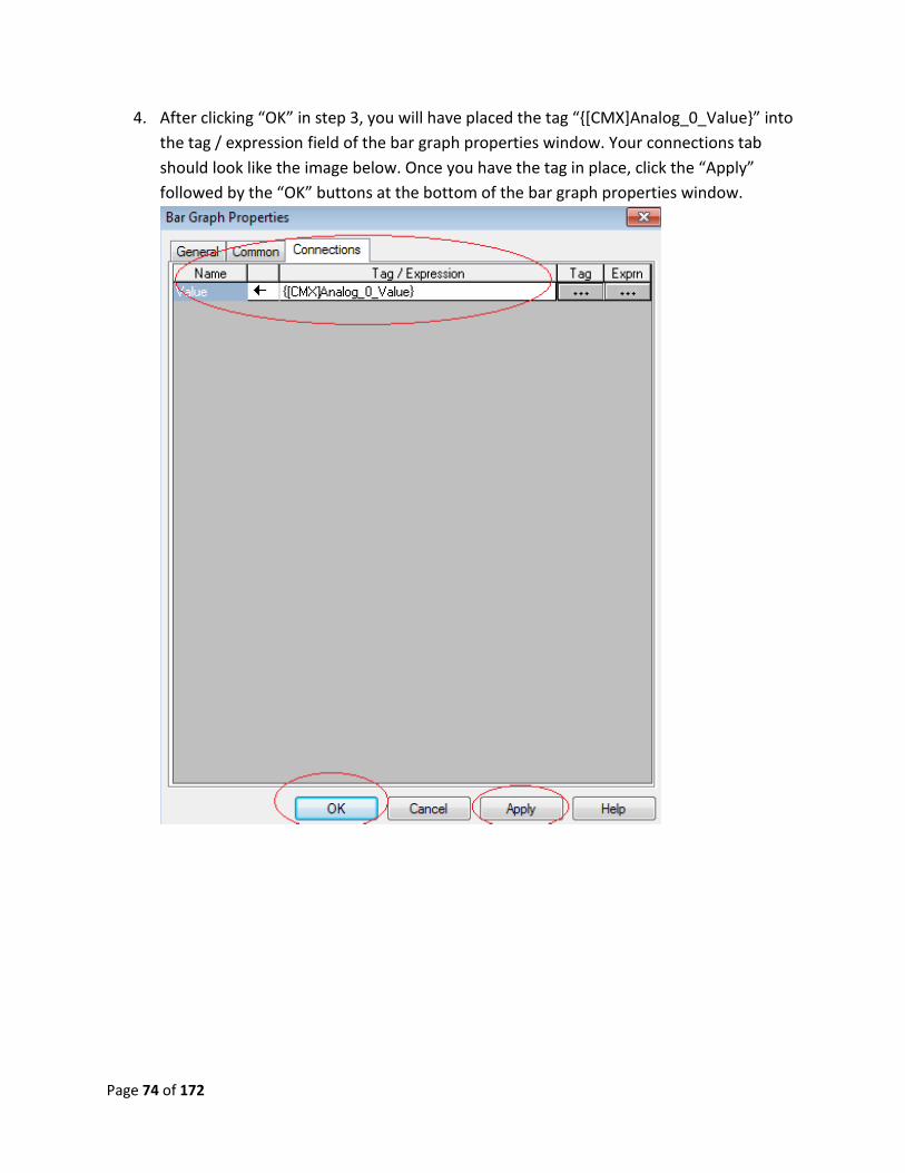
4. After clicking “OK” in step 3, you will have placed the tag “{[CMX]Analog_0_Value}” into
the tag / expression field of the bar graph properties window. Your connections tab
should look like the image below. Once you have the tag in place, click the “Apply”
followed by the “OK” buttons at the bottom of the bar graph properties window.
Page 75 of 172
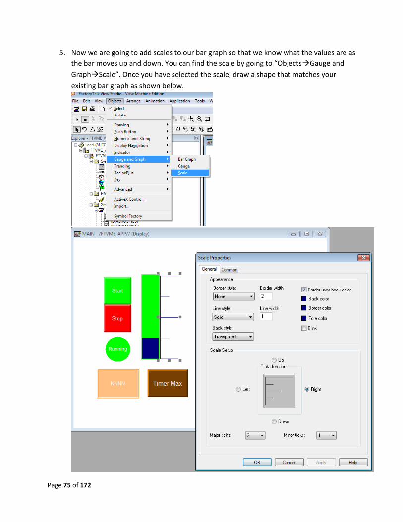
5. Now we are going to add scales to our bar graph so that we know what the values are as
the bar moves up and down. You can find the scale by going to “ObjectsGauge and
GraphScale”. Once you have selected the scale, draw a shape that matches your
existing bar graph as shown below.
Page 76 of 172
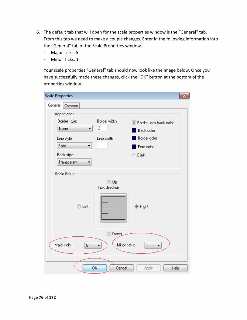
6. The default tab that will open for the scale properties window is the “General” tab.
From this tab we need to make a couple changes. Enter in the following information into
the “General” tab of the Scale Properties window.
- Major Ticks: 5
- Minor Ticks: 1
Your scale properties “General” tab should now look like the image below. Once you
have successfully made these changes, click the “OK” button at the bottom of the
properties window.
Page 77 of 172
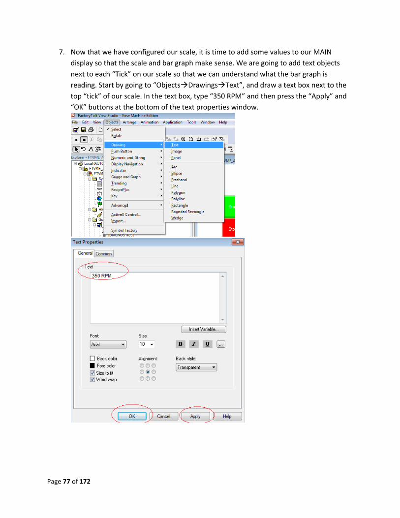
7. Now that we have configured our scale, it is time to add some values to our MAIN
display so that the scale and bar graph make sense. We are going to add text objects
next to each “Tick” on our scale so that we can understand what the bar graph is
reading. Start by going to “ObjectsDrawingsText”, and draw a text box next to the
top “tick” of our scale. In the text box, type “350 RPM” and then press the “Apply” and
“OK” buttons at the bottom of the text properties window.
Page 78 of 172
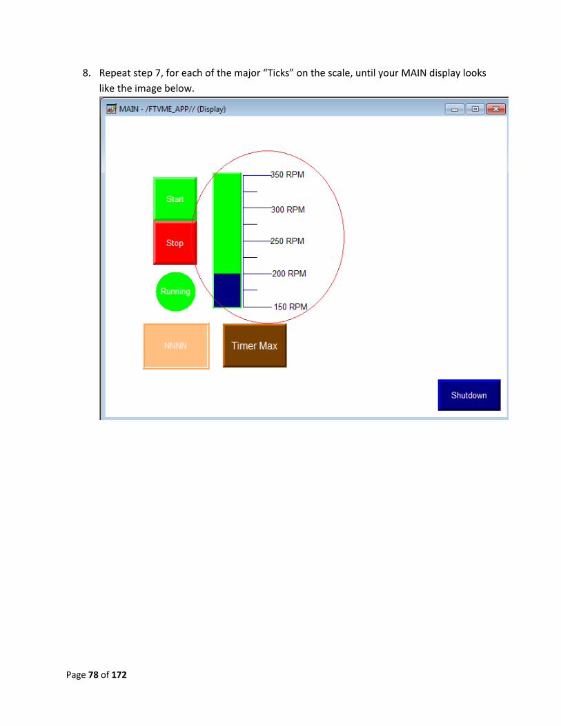
8. Repeat step 7, for each of the major “Ticks” on the scale, until your MAIN display looks
like the image below.
Page 79 of 172
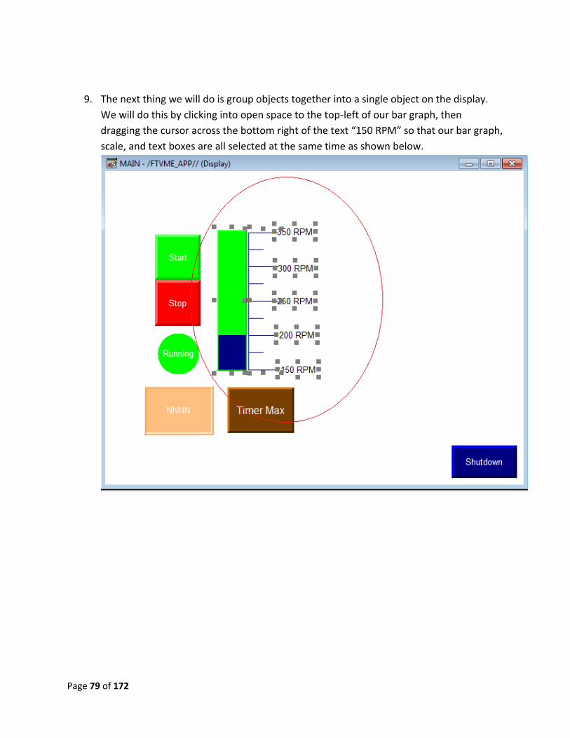
9. The next thing we will do is group objects together into a single object on the display.
We will do this by clicking into open space to the top-left of our bar graph, then
dragging the cursor across the bottom right of the text “150 RPM” so that our bar graph,
scale, and text boxes are all selected at the same time as shown below.
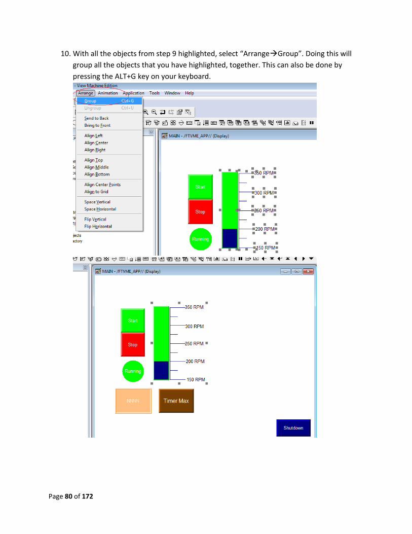
Page 80 of 172
10. With all the objects from step 9 highlighted, select “ArrangeGroup”. Doing this will
group all the objects that you have highlighted, together. This can also be done by
pressing the ALT+G key on your keyboard.
Page 81 of 172
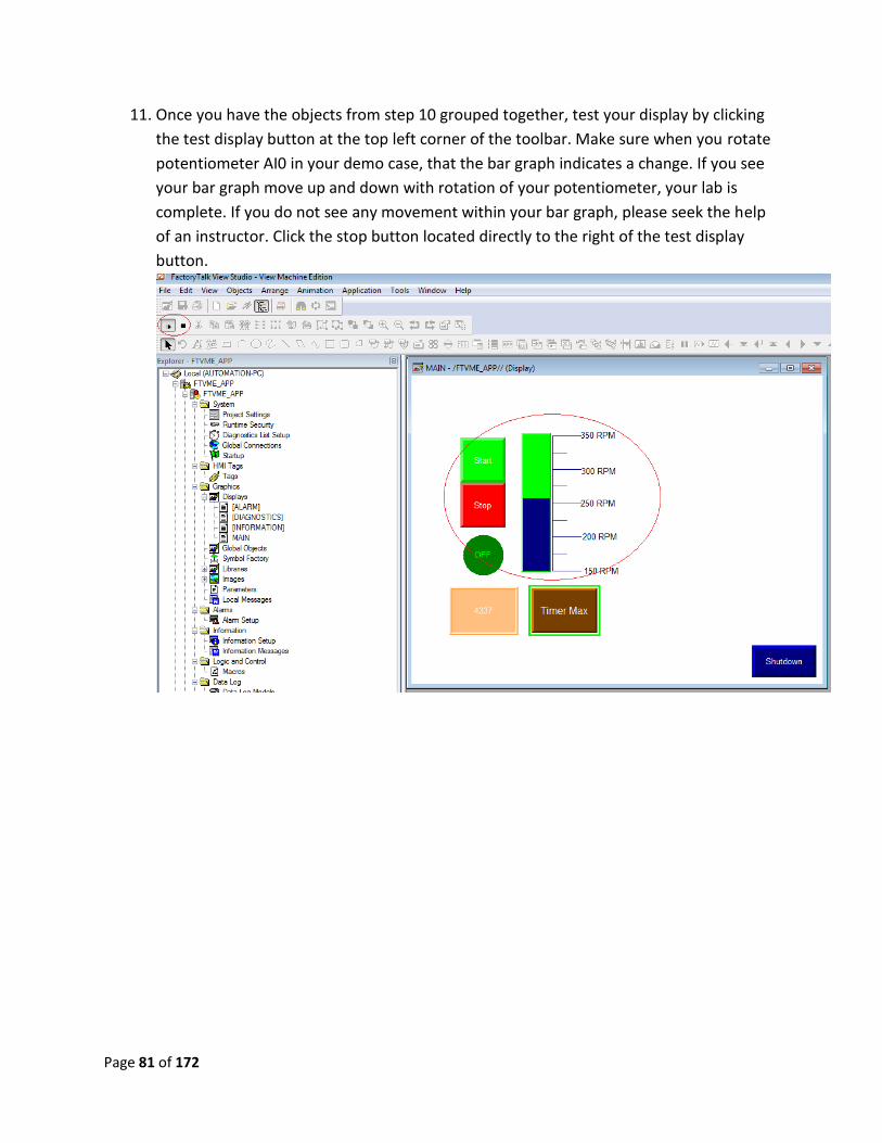
11. Once you have the objects from step 10 grouped together, test your display by clicking
the test display button at the top left corner of the toolbar. Make sure when you rotate
potentiometer AI0 in your demo case, that the bar graph indicates a change. If you see
your bar graph move up and down with rotation of your potentiometer, your lab is
complete. If you do not see any movement within your bar graph, please seek the help
of an instructor. Click the stop button located directly to the right of the test display
button.

Page 82 of 172
Lab 12 Review:
1. Does the scale have a min and max value that you can enter in the properties window?
If so, which tab?
2. How do you add numbers to your scale?
3. What is the max number of thresholds available on a bar graph?
This completes lab 12. Please wait for instructions to proceed further.
Page 83 of 172
Lab 13: Creating a Gauge
Objective: to introduce the concept of a gauge object on the PanelView Plus display. This
includes creation, configuration, and implementation. At the end of this lab, the user will be
able to create a gauge that displays valid process information, which could be used in many
different applications.
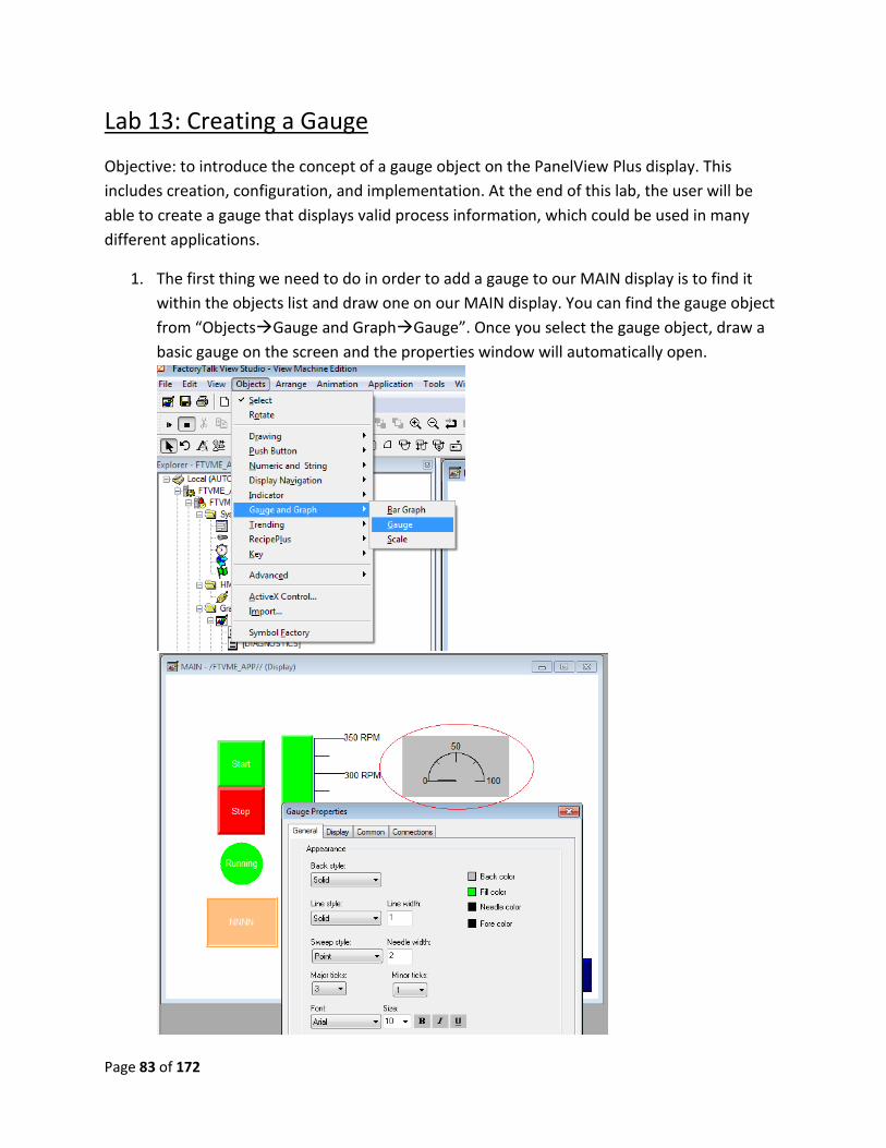
1. The first thing we need to do in order to add a gauge to our MAIN display is to find it
within the objects list and draw one on our MAIN display. You can find the gauge object
from “ObjectsGauge and GraphGauge”. Once you select the gauge object, draw a
basic gauge on the screen and the properties window will automatically open.
Page 84 of 172
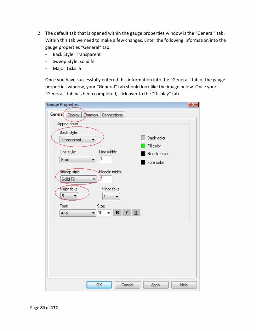
2. The default tab that is opened within the gauge properties window is the “General” tab.
Within this tab we need to make a few changes. Enter the following information into the
gauge properties “General” tab.
- Back Style: Transparent
- Sweep Style: solid fill
- Major Ticks: 5
Once you have successfully entered this information into the “General” tab of the gauge
properties window, your “General” tab should look like the image below. Once your
“General” tab has been completed, click over to the “Display” tab.
Page 85 of 172
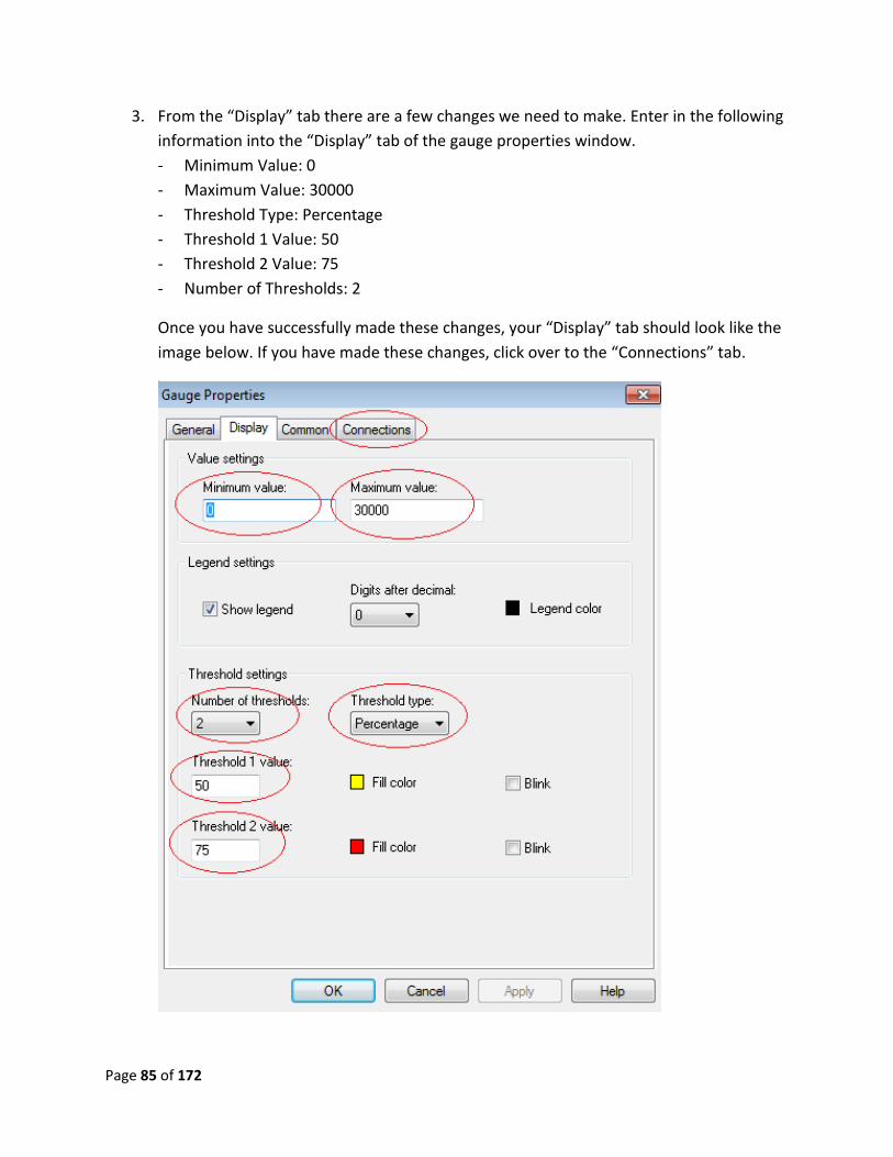
3. From the “Display” tab there are a few changes we need to make. Enter in the following
information into the “Display” tab of the gauge properties window.
- Minimum Value: 0
- Maximum Value: 30000
- Threshold Type: Percentage
- Threshold 1 Value: 50
- Threshold 2 Value: 75
- Number of Thresholds: 2
Once you have successfully made these changes, your “Display” tab should look like the
image below. If you have made these changes, click over to the “Connections” tab.
Page 86 of 172
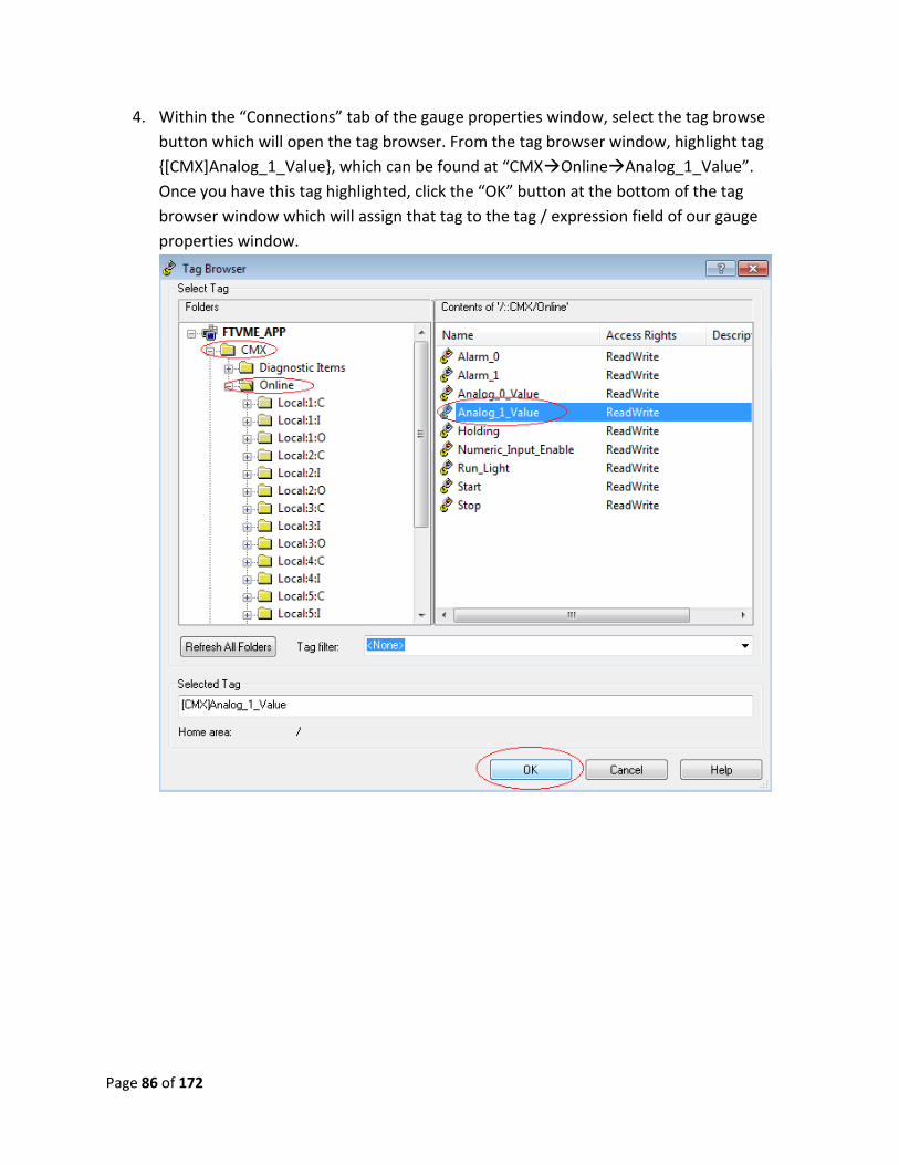
4. Within the “Connections” tab of the gauge properties window, select the tag browse
button which will open the tag browser. From the tag browser window, highlight tag
{[CMX]Analog_1_Value}, which can be found at “CMXOnlineAnalog_1_Value”.
Once you have this tag highlighted, click the “OK” button at the bottom of the tag
browser window which will assign that tag to the tag / expression field of our gauge
properties window.
Page 87 of 172
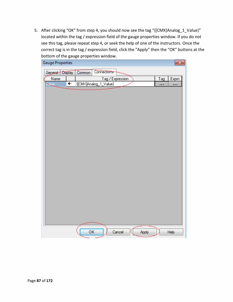
5. After clicking “OK” from step 4, you should now see the tag “{[CMX]Analog_1_Value}”
located within the tag / expression field of the gauge properties window. If you do not
see this tag, please repeat step 4, or seek the help of one of the instructors. Once the
correct tag is in the tag / expression field, click the “Apply” then the “OK” buttons at the
bottom of the gauge properties window.
Page 88 of 172
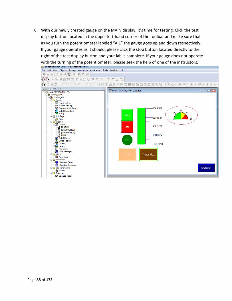
6. With our newly created gauge on the MAIN display, it’s time for testing. Click the test
display button located in the upper left-hand corner of the toolbar and make sure that
as you turn the potentiometer labeled “AI1” the gauge goes up and down respectively.
If your gauge operates as it should, please click the stop button located directly to the
right of the test display button and your lab is complete. If your gauge does not operate
with the turning of the potentiometer, please seek the help of one of the instructors.

Page 89 of 172
Lab 13 Review:
1. What is the maximum number of thresholds available for the gauge?
2. What are the 2 different sweep styles available for the gauge?
3. In the gauge property window, what tab can you set the minimum and maximum
values at?
This completes lab 13. Please wait for instructions to proceed further.
Page 90 of 172
Lab 14:Working with basic shapes
Objective: To provide a general overview of creating and configuring basic shapes on the
PanelView Plus display. By the end of this exercise, the user should be able to manipulate these
objects in an efficient and useful manner.
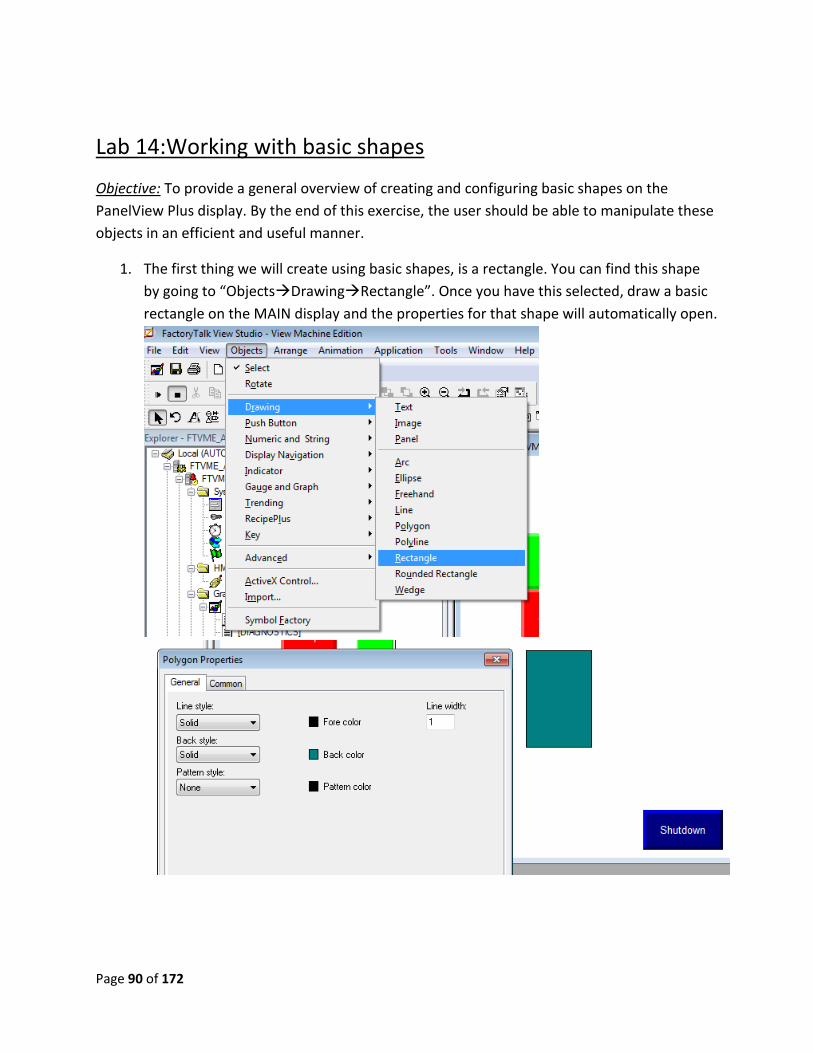
1. The first thing we will create using basic shapes, is a rectangle. You can find this shape
by going to “ObjectsDrawingRectangle”. Once you have this selected, draw a basic
rectangle on the MAIN display and the properties for that shape will automatically open.
Page 91 of 172
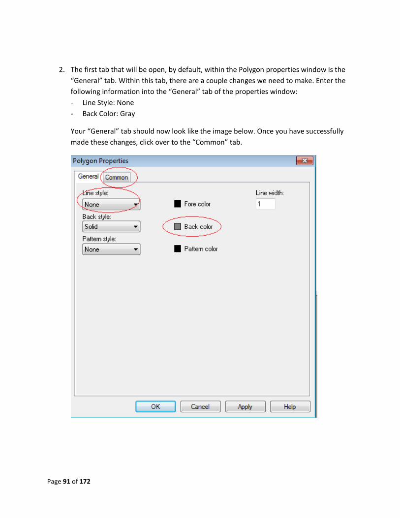
2. The first tab that will be open, by default, within the Polygon properties window is the
“General” tab. Within this tab, there are a couple changes we need to make. Enter the
following information into the “General” tab of the properties window:
- Line Style: None
- Back Color: Gray
Your “General” tab should now look like the image below. Once you have successfully
made these changes, click over to the “Common” tab.
Page 92 of 172
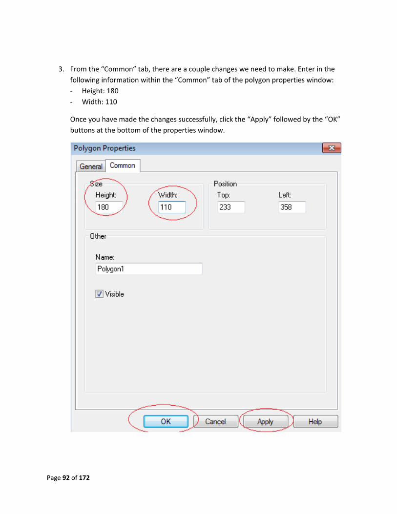
3. From the “Common” tab, there are a couple changes we need to make. Enter in the
following information within the “Common” tab of the polygon properties window:
- Height: 180
- Width: 110
Once you have made the changes successfully, click the “Apply” followed by the “OK”
buttons at the bottom of the properties window.
Page 93 of 172
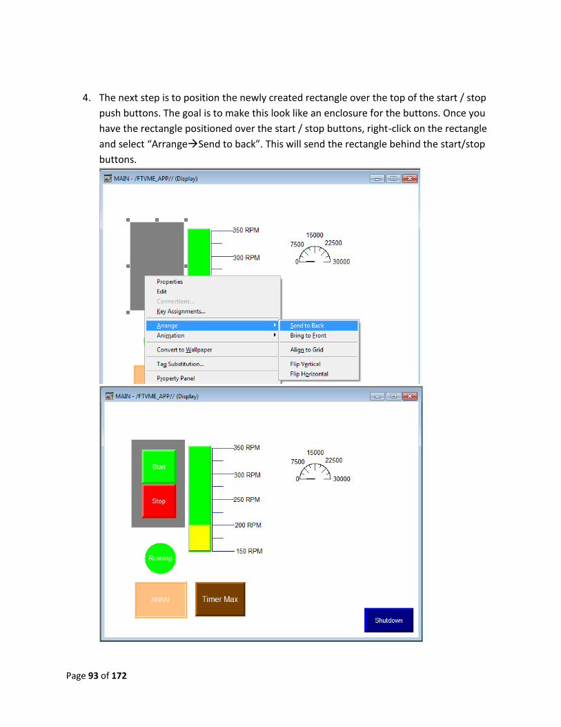
4. The next step is to position the newly created rectangle over the top of the start / stop
push buttons. The goal is to make this look like an enclosure for the buttons. Once you
have the rectangle positioned over the start / stop buttons, right-click on the rectangle
and select “ArrangeSend to back”. This will send the rectangle behind the start/stop
buttons.
Page 94 of 172
Lab 14 Review:
1. In reference to position on the display where is point 0,0?
2. When you right click on an object, what are the five different options when you select
arrange?
3. Can you resize an object in the properties window? Is there another less precise way to
resize?
This completes lab 14. Please wait for instructions to proceed further.
Page 95 of 172
Lab 15a: Working with Graphics
Objective: To provide a general overview of manipulating and configuring graphics on the
PanelView Plus display. This includes using a graphic to represent a pushbutton, as well as other
concepts.
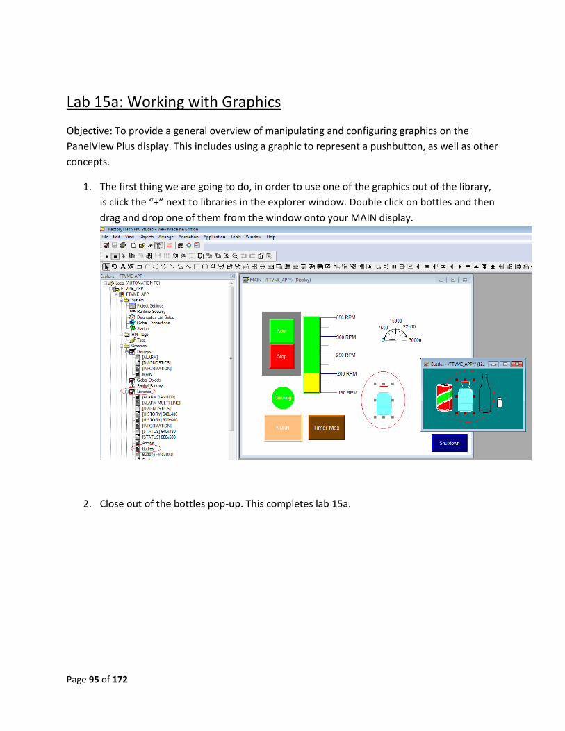
1. The first thing we are going to do, in order to use one of the graphics out of the library,
is click the “+” next to libraries in the explorer window. Double click on bottles and then
drag and drop one of them from the window onto your MAIN display.
2. Close out of the bottles pop-up. This completes lab 15a.
Page 96 of 172
Lab15b: Using Symbol Factory
Symbol factory is only available in FactoryTalk View 6.0 and newer. Add an object with the drag
and drop method and add an object with the image properties
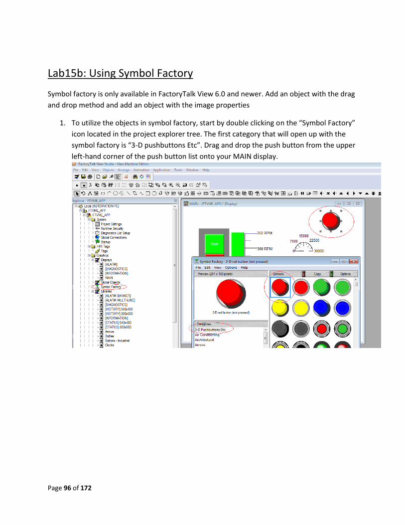
1. To utilize the objects in symbol factory, start by double clicking on the “Symbol Factory”
icon located in the project explorer tree. The first category that will open up with the
symbol factory is “3-D pushbuttons Etc”. Drag and drop the push button from the upper
left-hand corner of the push button list onto your MAIN display.
Page 97 of 172
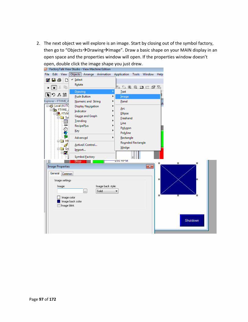
2. The next object we will explore is an image. Start by closing out of the symbol factory,
then go to “ObjectsDrawingImage”. Draw a basic shape on your MAIN display in an
open space and the properties window will open. If the properties window doesn’t
open, double click the image shape you just drew.
Page 98 of 172
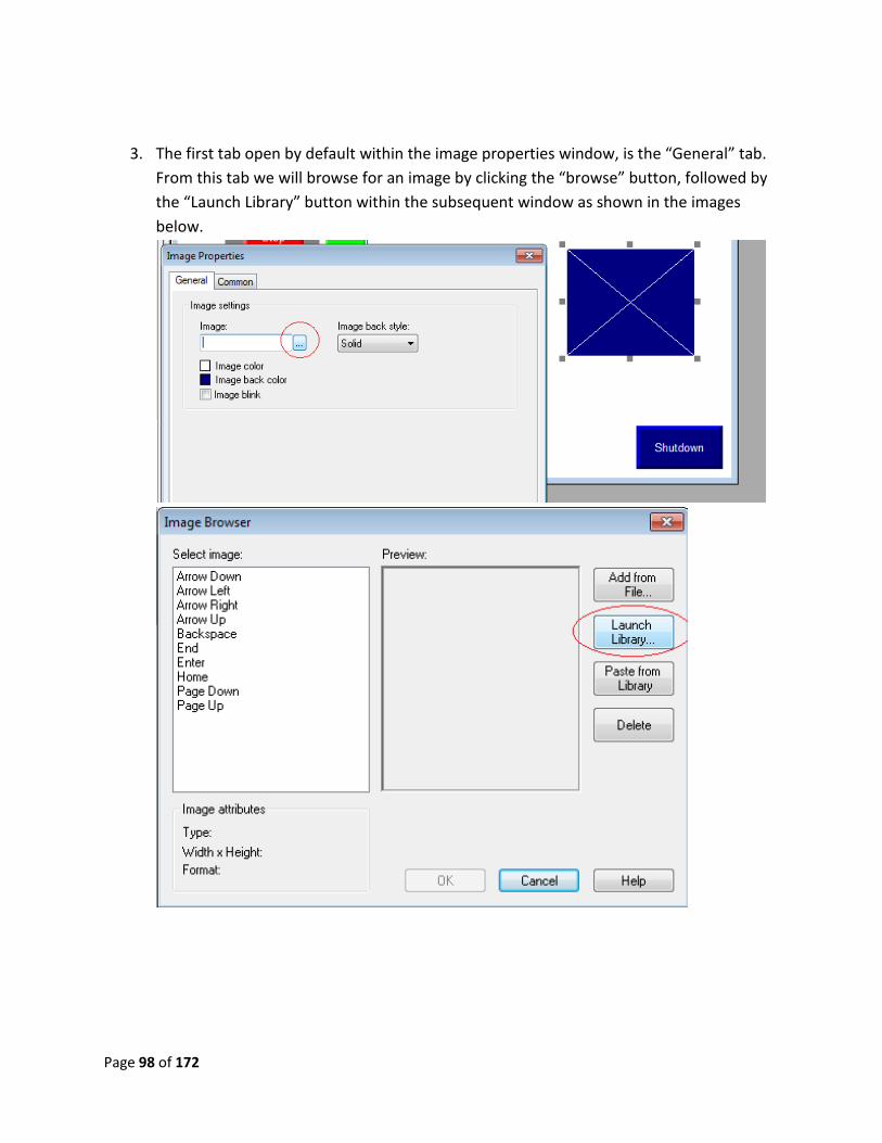
3. The first tab open by default within the image properties window, is the “General” tab.
From this tab we will browse for an image by clicking the “browse” button, followed by
the “Launch Library” button within the subsequent window as shown in the images
below.
Page 99 of 172
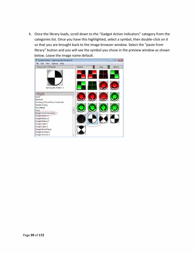
4. Once the library loads, scroll down to the “Gadget Action Indicators” category from the
categories list. Once you have this highlighted, select a symbol, then double-click on it
so that you are brought back to the image browser window. Select the “paste from
library” button and you will see the symbol you chose in the preview window as shown
below. Leave the image name default.
Page 100 of 172
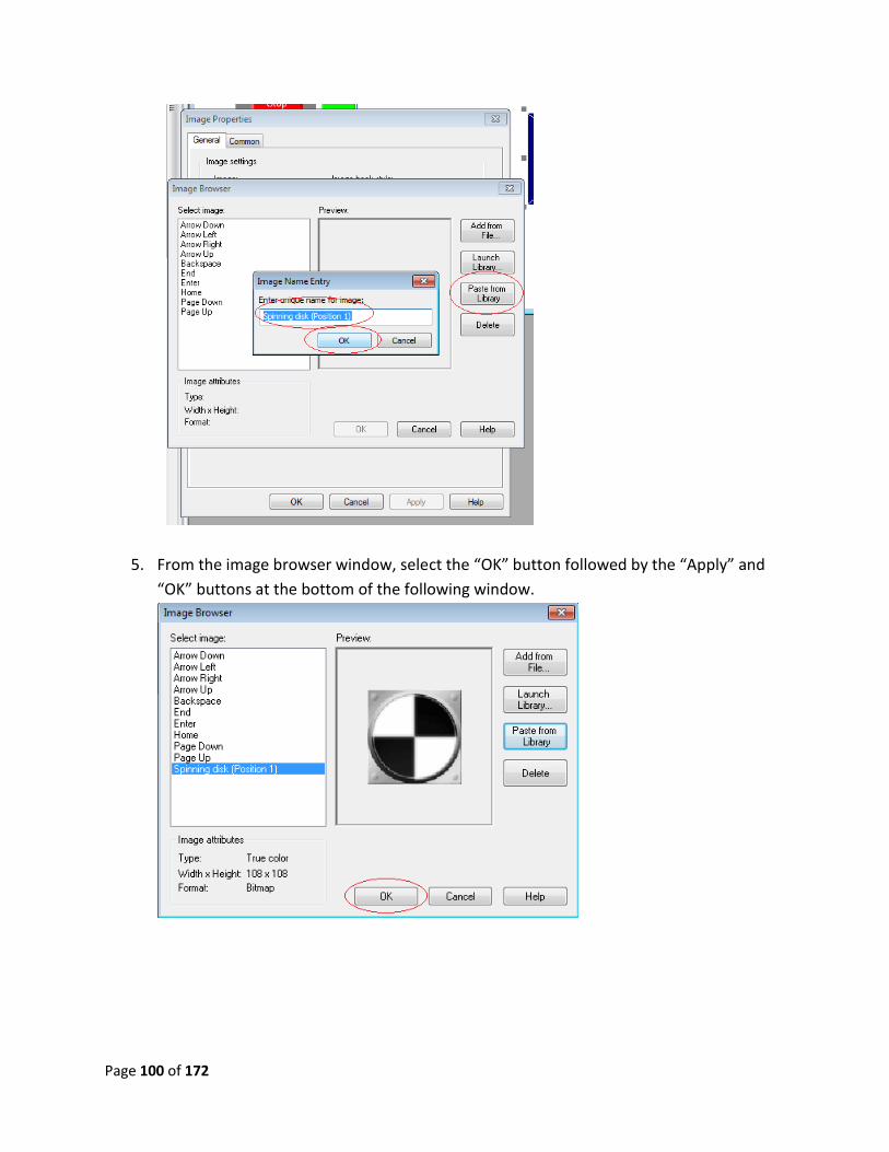
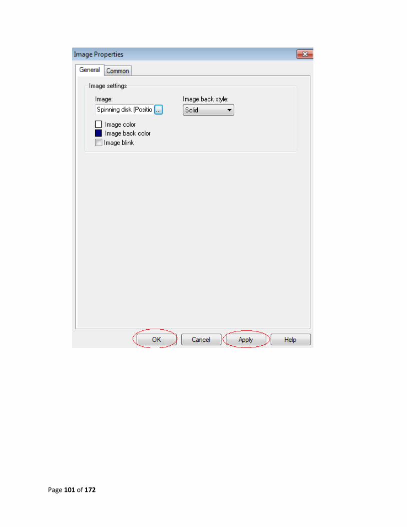
5. From the image browser window, select the “OK” button followed by the “Apply” and
“OK” buttons at the bottom of the following window.
Page 101 of 172
Page 102 of 172
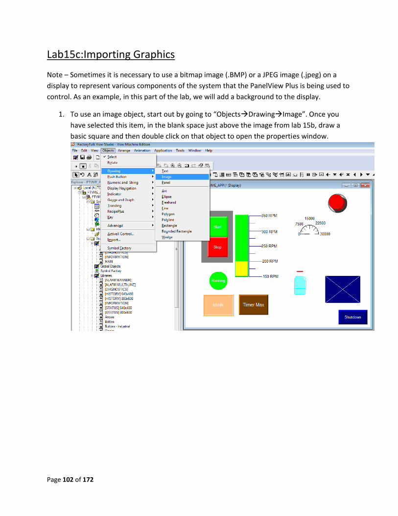
Lab15c:Importing Graphics
Note – Sometimes it is necessary to use a bitmap image (.BMP) or a JPEG image (.jpeg) on a
display to represent various components of the system that the PanelView Plus is being used to
control. As an example, in this part of the lab, we will add a background to the display.
1. To use an image object, start out by going to “ObjectsDrawingImage”. Once you
have selected this item, in the blank space just above the image from lab 15b, draw a
basic square and then double click on that object to open the properties window.
Page 103 of 172
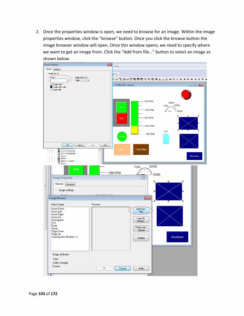
2. Once the properties window is open, we need to browse for an image. Within the image
properties window, click the “browse” button. Once you click the browse button the
image browser window will open. Once this window opens, we need to specify where
we want to get an image from. Click the “Add from file…” button to select an image as
shown below.
Page 104 of 172
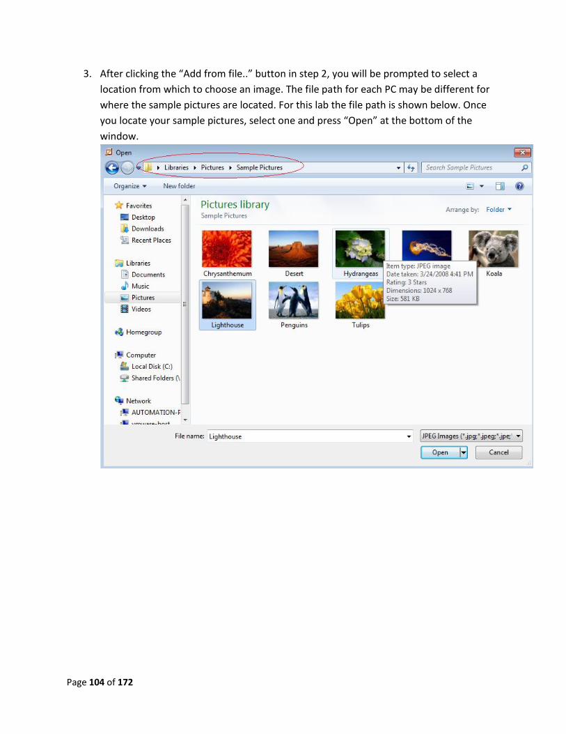
3. After clicking the “Add from file..” button in step 2, you will be prompted to select a
location from which to choose an image. The file path for each PC may be different for
where the sample pictures are located. For this lab the file path is shown below. Once
you locate your sample pictures, select one and press “Open” at the bottom of the
window.
Page 105 of 172
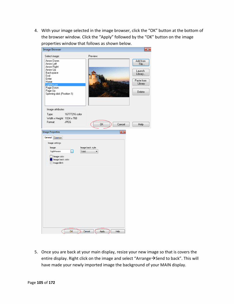
4. With your image selected in the image browser, click the “OK” button at the bottom of
the browser window. Click the “Apply” followed by the “OK” button on the image
properties window that follows as shown below.
5. Once you are back at your main display, resize your new image so that is covers the
entire display. Right click on the image and select “ArrangeSend to back”. This will
have made your newly imported image the background of your MAIN display.
Page 106 of 172
Lab 15 review:
1. Can you drag and drop gadgets from the symbol factory?
2. What two picture file types can you add to a display?
This now completes lab 15. Please wait for instructions to proceed further.
Page 107 of 172
Lab 16: Changing screens
Objective: To inform the user on how to change screens within their PanelView Plus project via
the display. At the end of this lab, the user will be able to move between multiple screens and
back again.
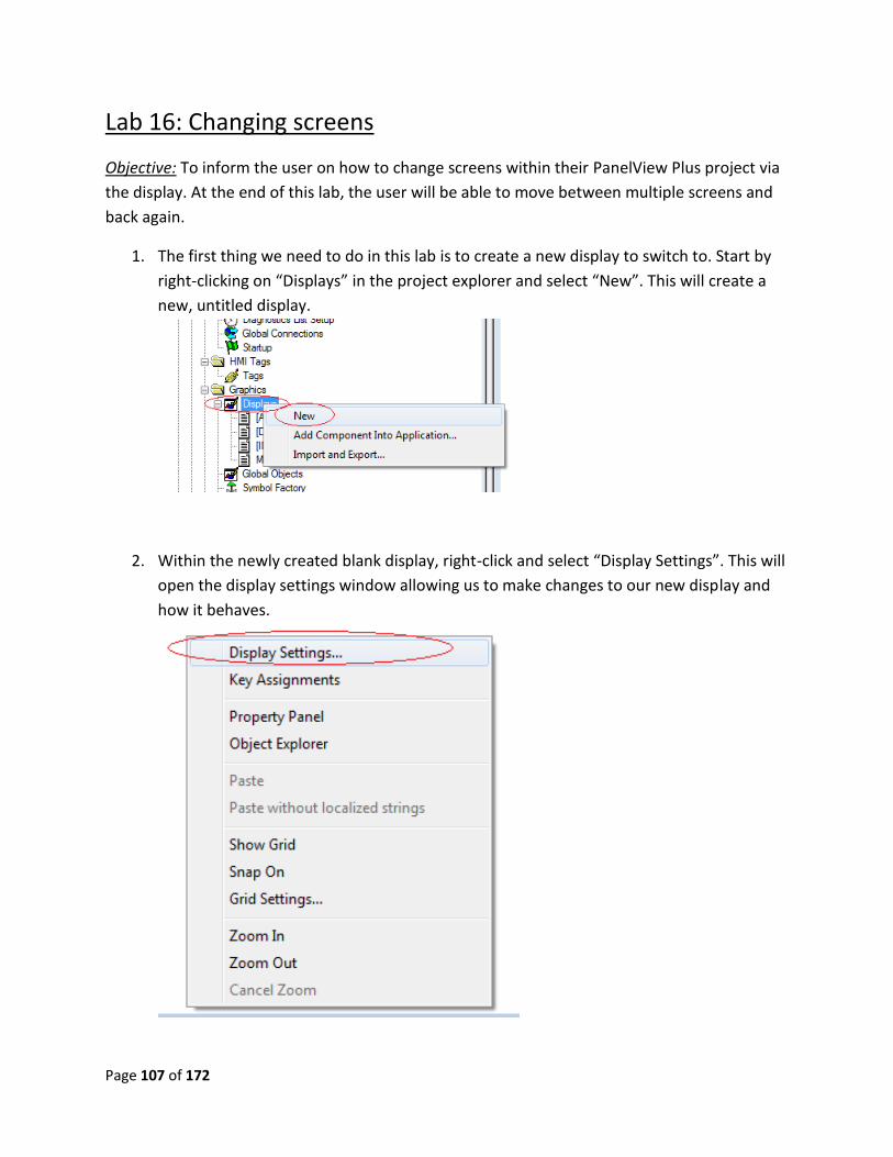
1. The first thing we need to do in this lab is to create a new display to switch to. Start by
right-clicking on “Displays” in the project explorer and select “New”. This will create a
new, untitled display.
2. Within the newly created blank display, right-click and select “Display Settings”. This will
open the display settings window allowing us to make changes to our new display and
how it behaves.
Page 108 of 172
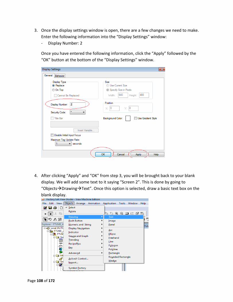
3. Once the display settings window is open, there are a few changes we need to make.
Enter the following information into the “Display Settings” window:
- Display Number: 2
Once you have entered the following information, click the “Apply” followed by the
“OK” button at the bottom of the “Display Settings” window.
4. After clicking “Apply” and “OK” from step 3, you will be brought back to your blank
display. We will add some text to it saying “Screen 2”. This is done by going to
“ObjectsDrawingText”. Once this option is selected, draw a basic text box on the
blank display.
Page 109 of 172
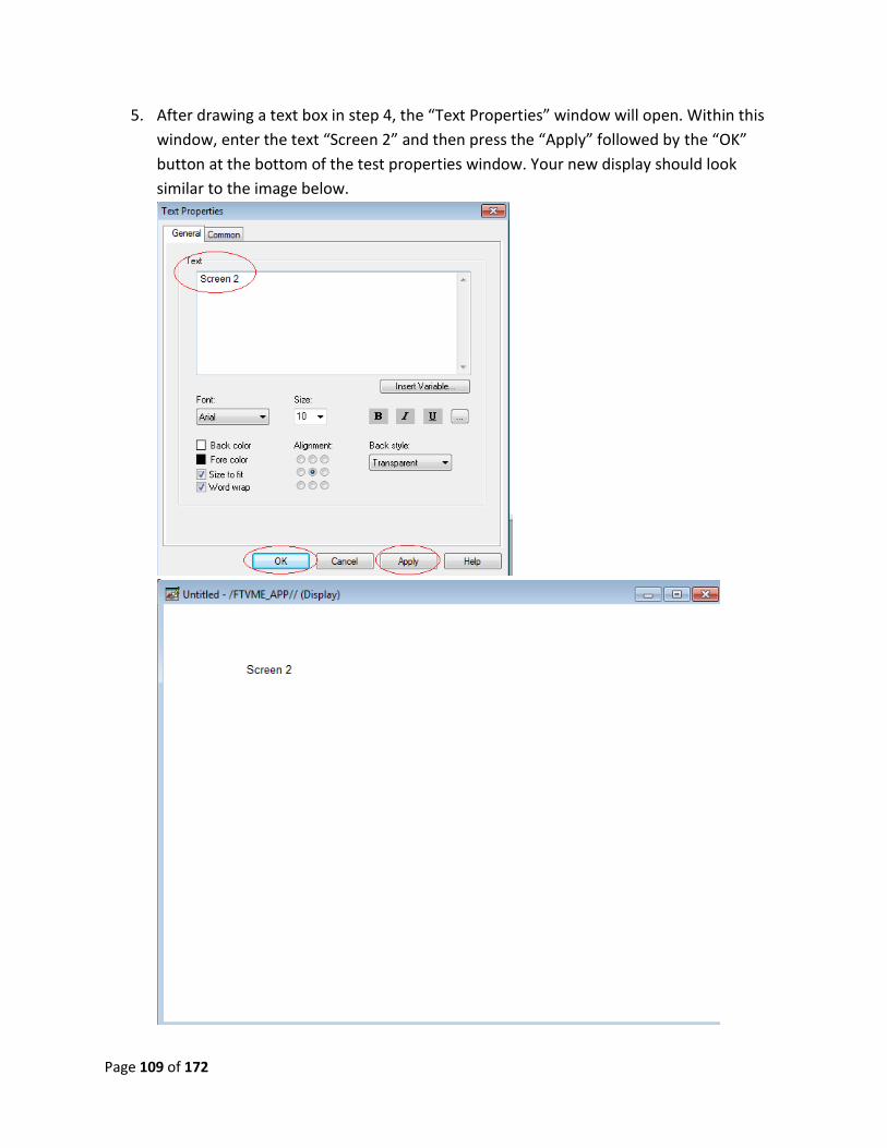
5. After drawing a text box in step 4, the “Text Properties” window will open. Within this
window, enter the text “Screen 2” and then press the “Apply” followed by the “OK”
button at the bottom of the test properties window. Your new display should look
similar to the image below.
Page 110 of 172
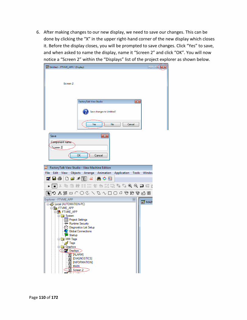
6. After making changes to our new display, we need to save our changes. This can be
done by clicking the “X” in the upper right-hand corner of the new display which closes
it. Before the display closes, you will be prompted to save changes. Click “Yes” to save,
and when asked to name the display, name it “Screen 2” and click “OK”. You will now
notice a “Screen 2” within the “Displays” list of the project explorer as shown below.
Page 111 of 172
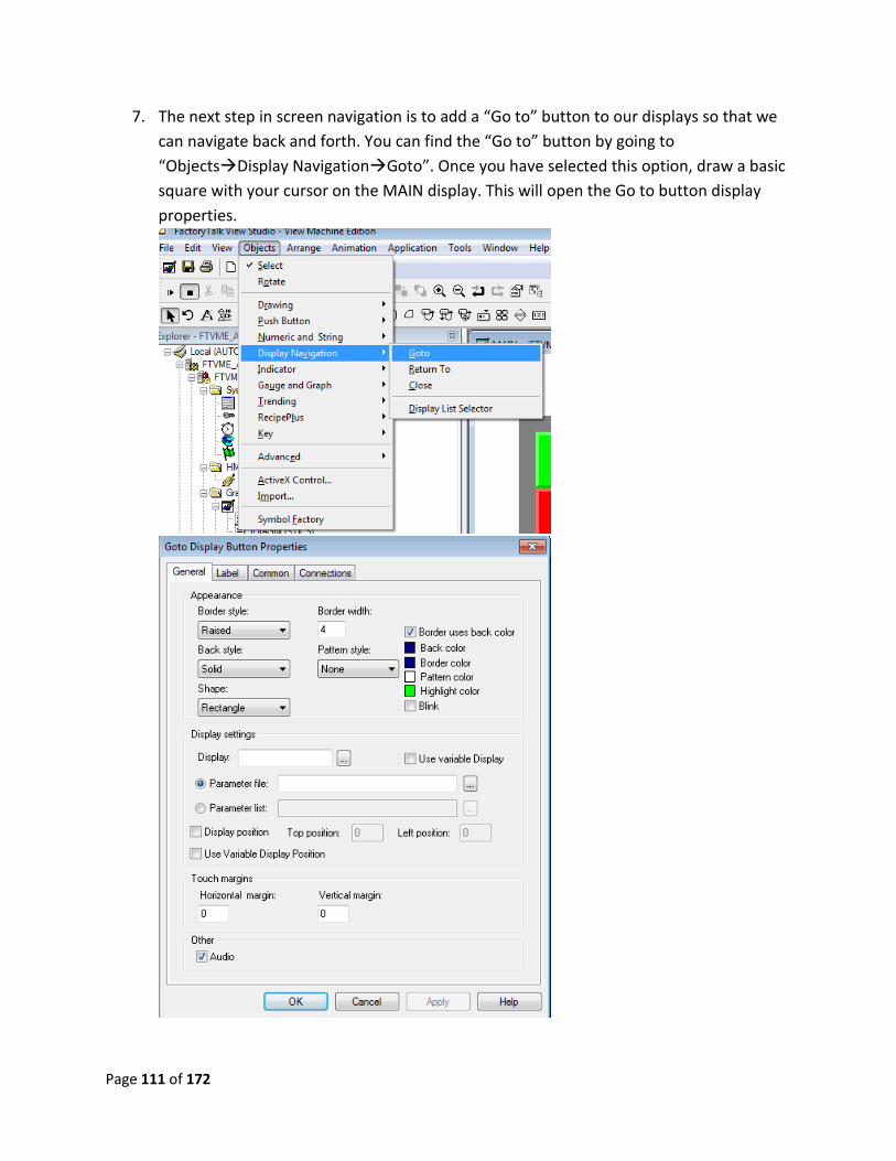
7. The next step in screen navigation is to add a “Go to” button to our displays so that we
can navigate back and forth. You can find the “Go to” button by going to
“ObjectsDisplay NavigationGoto”. Once you have selected this option, draw a basic
square with your cursor on the MAIN display. This will open the Go to button display
properties.
Page 112 of 172
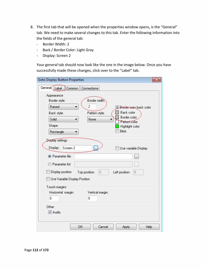
8. The first tab that will be opened when the properties window opens, is the “General”
tab. We need to make several changes to this tab. Enter the following information into
the fields of the general tab:
- Border Width: 2
- Back / Border Color: Light Gray
- Display: Screen 2
Your general tab should now look like the one in the image below. Once you have
successfully made these changes, click over to the “Label” tab.
Page 113 of 172
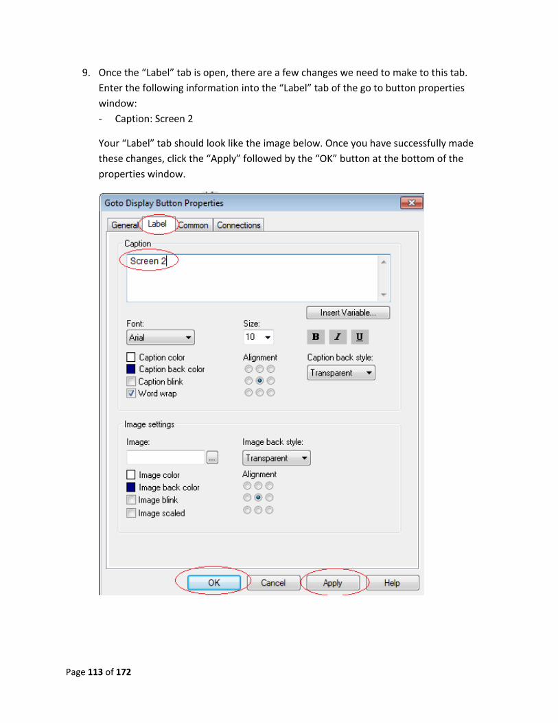
9. Once the “Label” tab is open, there are a few changes we need to make to this tab.
Enter the following information into the “Label” tab of the go to button properties
window:
- Caption: Screen 2
Your “Label” tab should look like the image below. Once you have successfully made
these changes, click the “Apply” followed by the “OK” button at the bottom of the
properties window.
Page 114 of 172
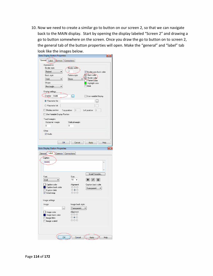
10. Now we need to create a similar go to button on our screen 2, so that we can navigate
back to the MAIN display. Start by opening the display labeled “Screen 2” and drawing a
go to button somewhere on the screen. Once you draw the go to button on to screen 2,
the general tab of the button properties will open. Make the “general” and “label” tab
look like the images below.
Page 115 of 172
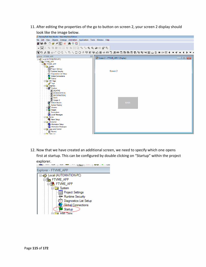
11. After editing the properties of the go to button on screen 2, your screen 2 display should
look like the image below.
12. Now that we have created an additional screen, we need to specify which one opens
first at startup. This can be configured by double clicking on “Startup” within the project
explorer.
Page 116 of 172
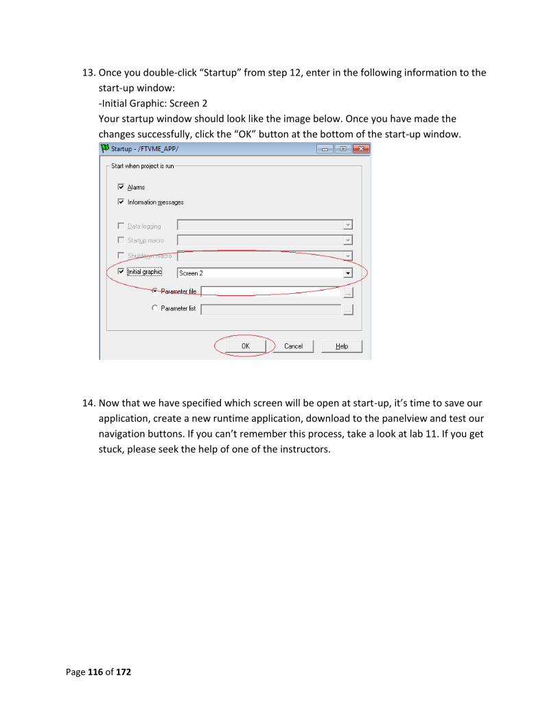
13. Once you double-click “Startup” from step 12, enter in the following information to the
start-up window:
-Initial Graphic: Screen 2
Your startup window should look like the image below. Once you have made the
changes successfully, click the “OK” button at the bottom of the start-up window.
14. Now that we have specified which screen will be open at start-up, it’s time to save our
application, create a new runtime application, download to the panelview and test our
navigation buttons. If you can’t remember this process, take a look at lab 11. If you get
stuck, please seek the help of one of the instructors.

Page 117 of 172
Lab 16 Review:
1. In the go to button properties, what tab do you identify the display you want to go to?
2. Where do you select the initial graphic for the program?
3. How do you create a new display?
4. How do you rename a display?
5. When “Replace” is selected as the “Display Type” what happens to the open display?
This now completes lab 16. Please wait for instructions to proceed further.
Page 118 of 172
Advanced lab 1: Alarms
Objective: To guide the user through creation and configuration of alarms to be used to notify
the operator of various issues within the system. In this lab, we will cover alerting the operator
when the motor speed is too high. By the end of this lab, the usershall be able to make alarms
for important on-the-job system information.
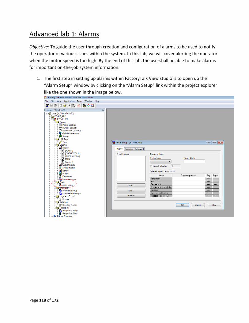
1. The first step in setting up alarms within FactoryTalk View studio is to open up the
“Alarm Setup” window by clicking on the “Alarm Setup” link within the project explorer
like the one shown in the image below.
Page 119 of 172
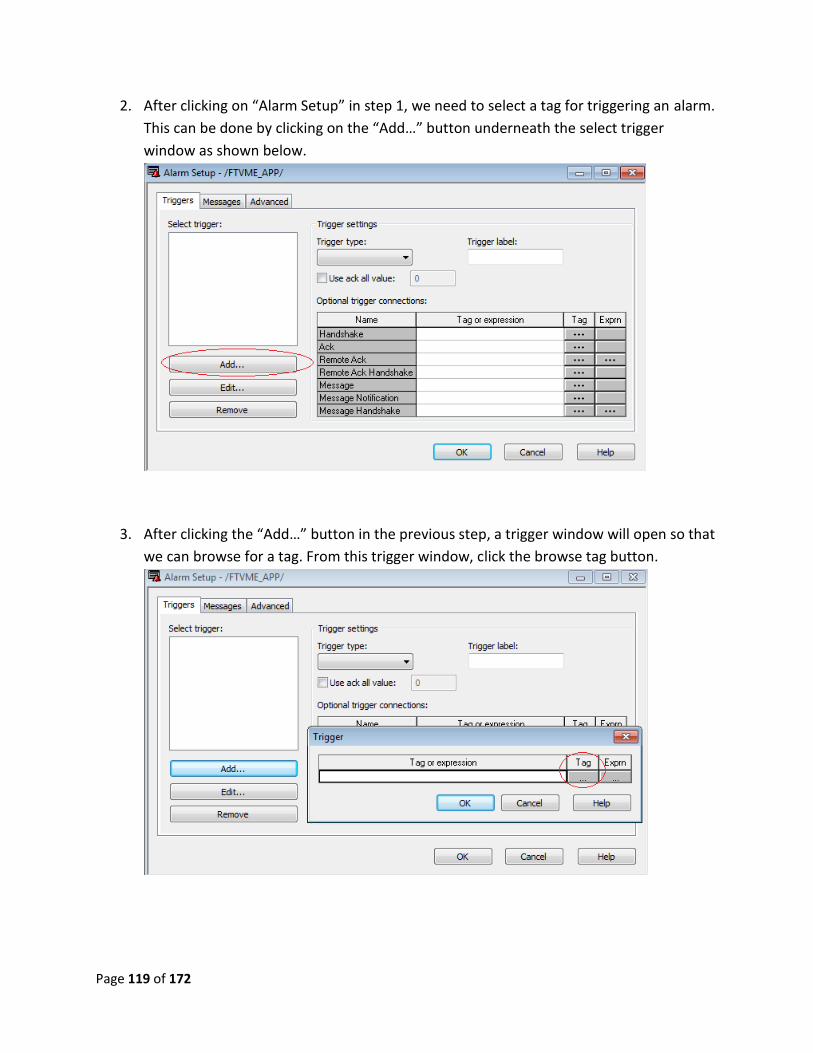
2. After clicking on “Alarm Setup” in step 1, we need to select a tag for triggering an alarm.
This can be done by clicking on the “Add…” button underneath the select trigger
window as shown below.
3. After clicking the “Add…” button in the previous step, a trigger window will open so that
we can browse for a tag. From this trigger window, click the browse tag button.

Page 120 of 172
4. From the tag browser window, find the “Alarm_0” tag. This can be found by going to
“CMXOnlineAlarm_0”. Once you have this tag highlighted, click the “OK” button at
the bottom of the tag browser window. This will assign the tag “Alarm_0” to our alarm
trigger from the previous step.
5. From the trigger window, you should see the tag “Alarm_0” within the tag or expression
field. Press the “OK” button and you will be brought back to the alarm setup window
with your newly configured trigger.
Page 121 of 172
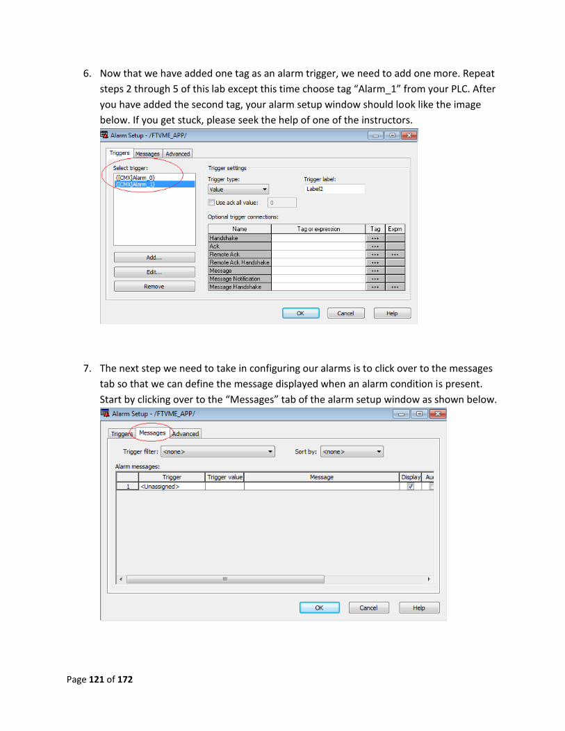
6. Now that we have added one tag as an alarm trigger, we need to add one more. Repeat
steps 2 through 5 of this lab except this time choose tag “Alarm_1” from your PLC. After
you have added the second tag, your alarm setup window should look like the image
below. If you get stuck, please seek the help of one of the instructors.
7. The next step we need to take in configuring our alarms is to click over to the messages
tab so that we can define the message displayed when an alarm condition is present.
Start by clicking over to the “Messages” tab of the alarm setup window as shown below.
Page 122 of 172
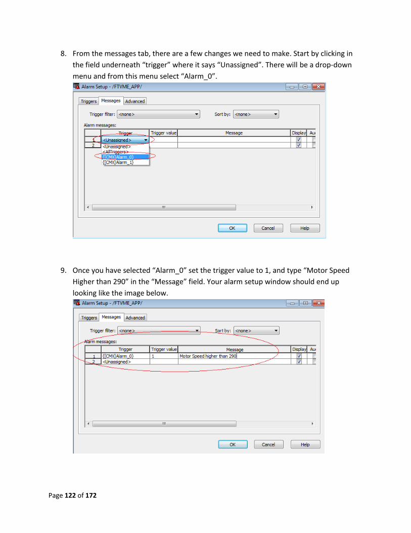
8. From the messages tab, there are a few changes we need to make. Start by clicking in
the field underneath “trigger” where it says “Unassigned”. There will be a drop-down
menu and from this menu select “Alarm_0”.
9. Once you have selected “Alarm_0” set the trigger value to 1, and type “Motor Speed
Higher than 290” in the “Message” field. Your alarm setup window should end up
looking like the image below.
Page 123 of 172
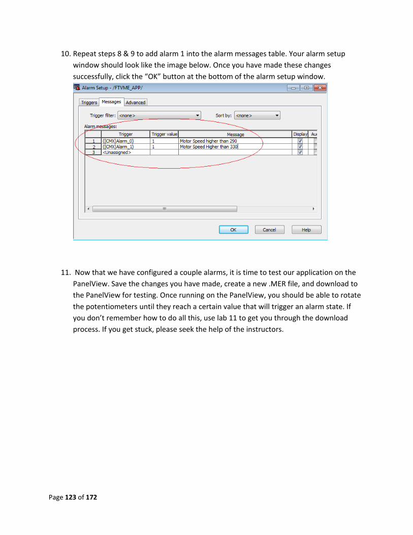
10. Repeat steps 8 & 9 to add alarm 1 into the alarm messages table. Your alarm setup
window should look like the image below. Once you have made these changes
successfully, click the “OK” button at the bottom of the alarm setup window.
11. Now that we have configured a couple alarms, it is time to test our application on the
PanelView. Save the changes you have made, create a new .MER file, and download to
the PanelView for testing. Once running on the PanelView, you should be able to rotate
the potentiometers until they reach a certain value that will trigger an alarm state. If
you don’t remember how to do all this, use lab 11 to get you through the download
process. If you get stuck, please seek the help of the instructors.
Page 124 of 172
Advanced Lab 1 Review:
1. Inside the alarm setup window, where do you add tags that will trigger an alarm?
2. By default, what also appears with your message inside the alarm banner?
3. What happens when the alarm bit goes high and then goes low before the alarm banner
is closed or the alarm is acknowledged.
4. What happens to an alarm if another occurs after it? Does it still display?
This completes advanced lab 1. Please wait for instructions to proceed further.
Page 125 of 172
Advanced lab 2: Application Backup and Restore
With the “Application Manager” you can back up and restore applications. When as application
is backed up, a file is created with a .apa file extension. Normally, all of the application files are
stored within FactoryTalk View Studio’s root directories. Backing up a file allows you to store an
application in a folder of your choice to be used later. A backed up file can also be emailed and
restored on a different computer. When a runtime file is created, a .MER file is produced. It is
important to realize that this file can be transferred to a different computer, but will open in
FactoryTalk ME Station instead of FactoryTalk View Studio, allowing the runtime to be viewed,
but not edited.
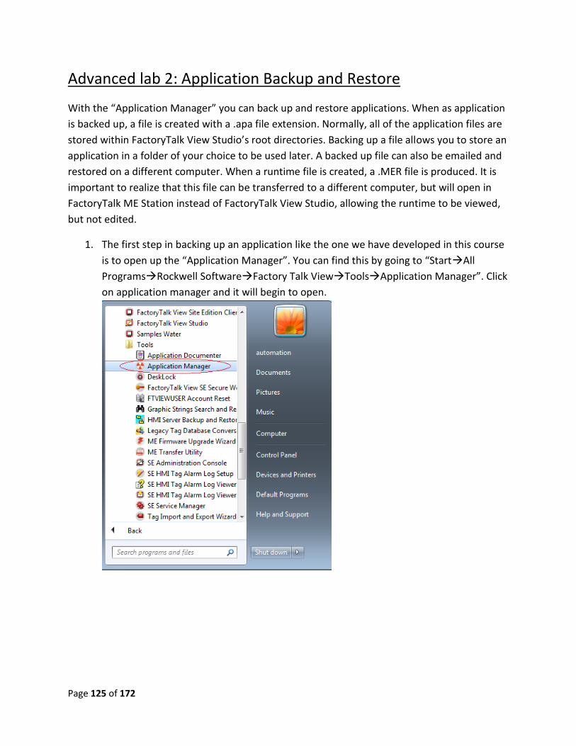
1. The first step in backing up an application like the one we have developed in this course
is to open up the “Application Manager”. You can find this by going to “StartAll
ProgramsRockwell SoftwareFactory Talk ViewToolsApplication Manager”. Click
on application manager and it will begin to open.
Page 126 of 172
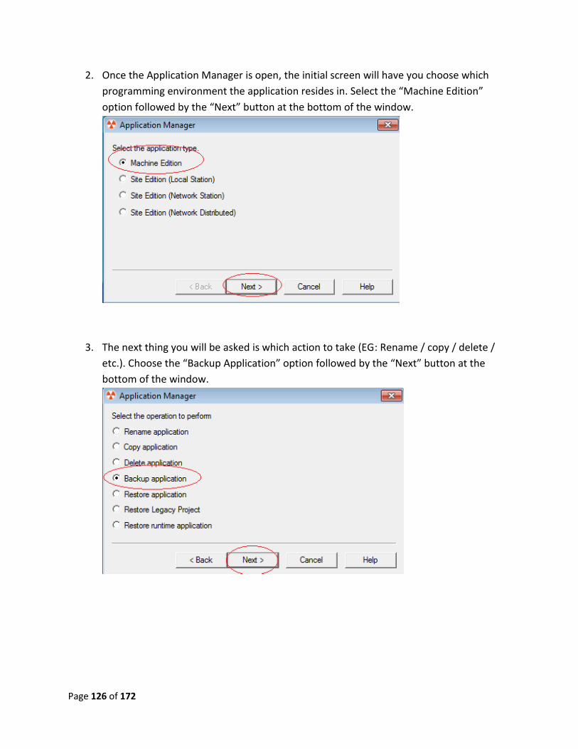
2. Once the Application Manager is open, the initial screen will have you choose which
programming environment the application resides in. Select the “Machine Edition”
option followed by the “Next” button at the bottom of the window.
3. The next thing you will be asked is which action to take (EG: Rename / copy / delete /
etc.). Choose the “Backup Application” option followed by the “Next” button at the
bottom of the window.
Page 127 of 172
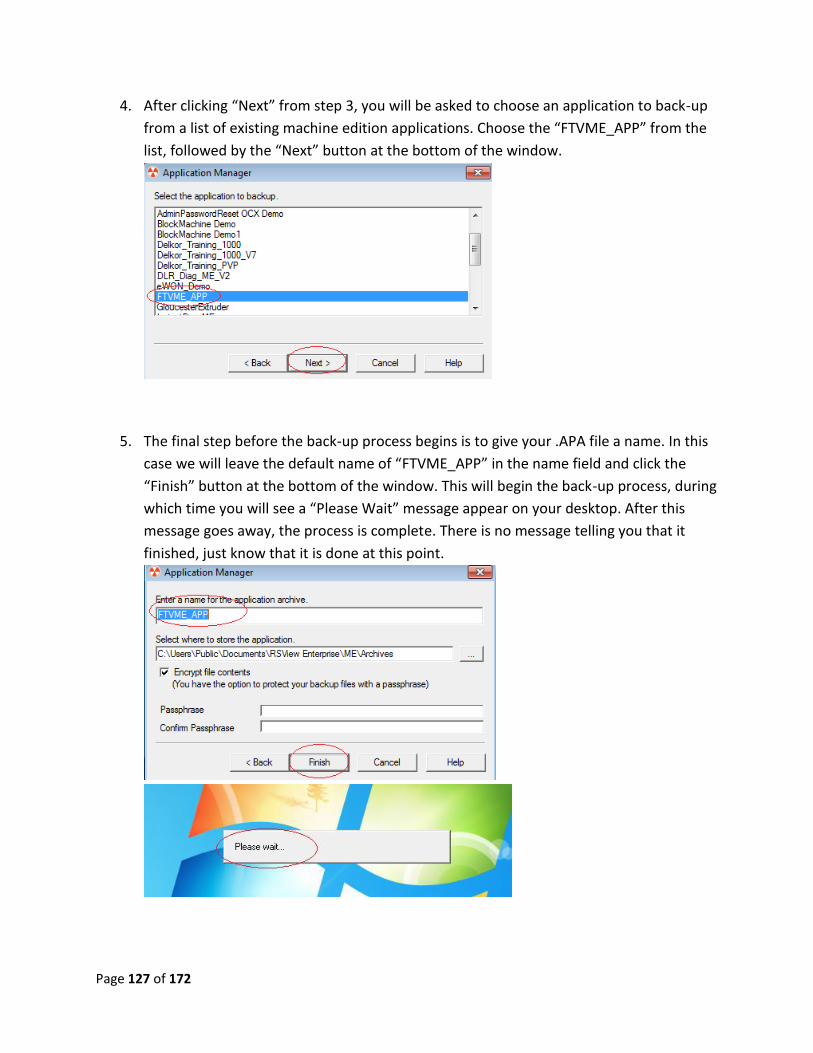
4. After clicking “Next” from step 3, you will be asked to choose an application to back-up
from a list of existing machine edition applications. Choose the “FTVME_APP” from the
list, followed by the “Next” button at the bottom of the window.
5. The final step before the back-up process begins is to give your .APA file a name. In this
case we will leave the default name of “FTVME_APP” in the name field and click the
“Finish” button at the bottom of the window. This will begin the back-up process, during
which time you will see a “Please Wait” message appear on your desktop. After this
message goes away, the process is complete. There is no message telling you that it
finished, just know that it is done at this point.
Page 128 of 172
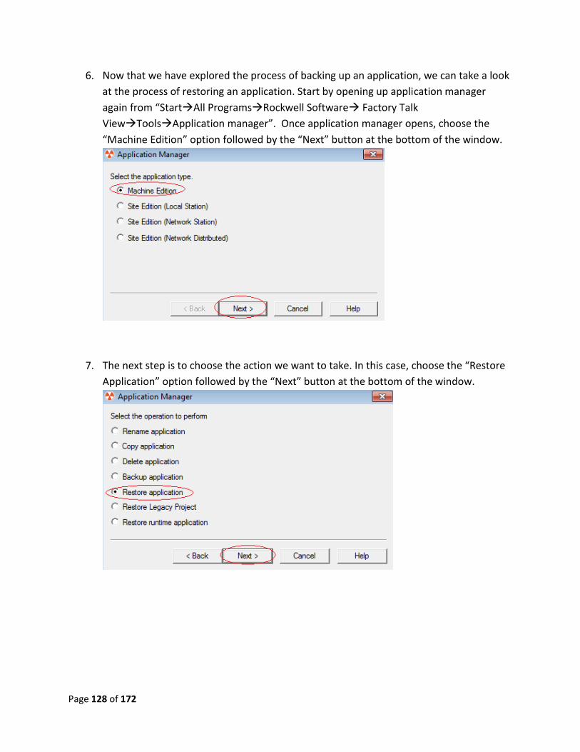
6. Now that we have explored the process of backing up an application, we can take a look
at the process of restoring an application. Start by opening up application manager
again from “StartAll ProgramsRockwell Software Factory Talk
ViewToolsApplication manager”. Once application manager opens, choose the
“Machine Edition” option followed by the “Next” button at the bottom of the window.
7. The next step is to choose the action we want to take. In this case, choose the “Restore
Application” option followed by the “Next” button at the bottom of the window.
Page 129 of 172
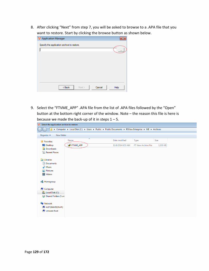
8. After clicking “Next” from step 7, you will be asked to browse to a .APA file that you
want to restore. Start by clicking the browse button as shown below.
9. Select the “FTVME_APP” .APA file from the list of .APA files followed by the “Open”
button at the bottom right corner of the window. Note – the reason this file is here is
because we made the back-up of it in steps 1 – 5.
Page 130 of 172
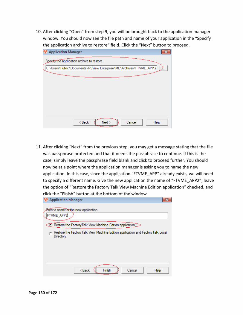
10. After clicking “Open” from step 9, you will be brought back to the application manager
window. You should now see the file path and name of your application in the “Specify
the application archive to restore” field. Click the “Next” button to proceed.
11. After clicking “Next” from the previous step, you may get a message stating that the file
was passphrase protected and that it needs the passphrase to continue. If this is the
case, simply leave the passphrase field blank and click to proceed further. You should
now be at a point where the application manager is asking you to name the new
application. In this case, since the application “FTVME_APP” already exists, we will need
to specify a different name. Give the new application the name of “FTVME_APP2”, leave
the option of “Restore the Factory Talk View Machine Edition application” checked, and
click the “Finish” button at the bottom of the window.
Page 131 of 172
12. After clicking “Finish” from step 11, there will be a message on your desktop saying
“Please Wait”. During this time, the application we specified in step 11 is being
restored. Once this message goes away, the process is completed.
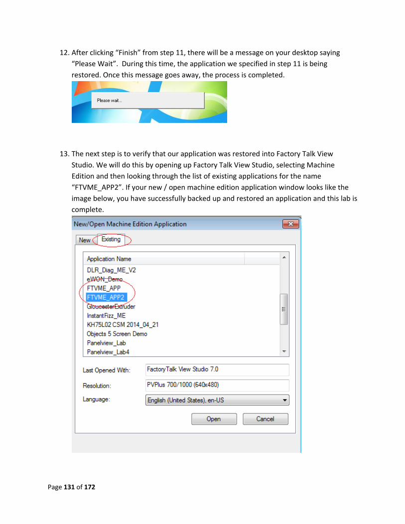
13. The next step is to verify that our application was restored into Factory Talk View
Studio. We will do this by opening up Factory Talk View Studio, selecting Machine
Edition and then looking through the list of existing applications for the name
“FTVME_APP2”. If your new / open machine edition application window looks like the
image below, you have successfully backed up and restored an application and this lab is
complete.

Page 132 of 172
Advanced Lab 2 Review:
1. When an application is backed up, what is the new file extension?
2. What is the benefit of creating a backup file?
3. Can you save the backup file in any location or is it locked to a defined folder?
4. When restoring a backup file, can you create a new name for the file?
This now completes the advanced lab 2. Please wait for instructions to proceed further.
Page 133 of 172
Advanced Lab 3: Uploading a program
In terms of a PanelView (source) and a computer (destination) the process of uploading is
described as transferring a runtime file (.MER) from the source to the destination. This file type
is only used by a PanelView or ME Station and cannot be used in FactoryTalk View Studio. Later
in this manual, you will convert the runtime (.MER) file to a design time file that can be used
with FactoryTalk View Studio for program edits.
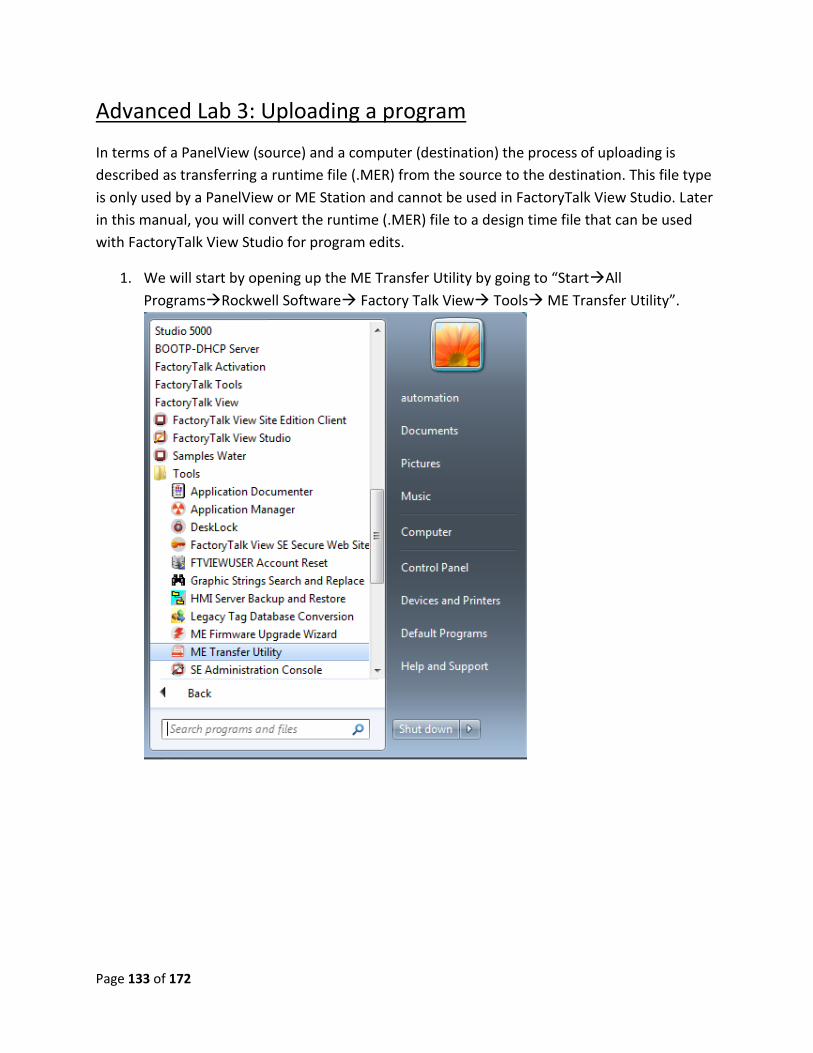
1. We will start by opening up the ME Transfer Utility by going to “StartAll
ProgramsRockwell Software Factory Talk View Tools ME Transfer Utility”.
Page 134 of 172
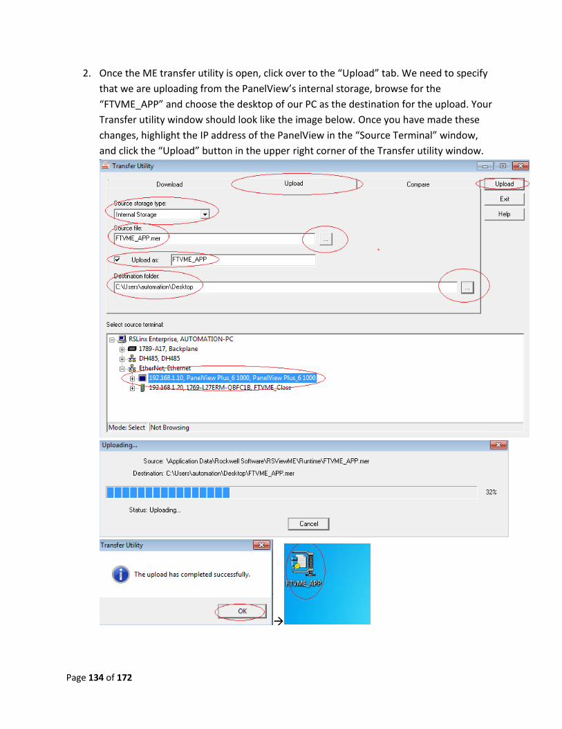
2. Once the ME transfer utility is open, click over to the “Upload” tab. We need to specify
that we are uploading from the PanelView’s internal storage, browse for the
“FTVME_APP” and choose the desktop of our PC as the destination for the upload. Your
Transfer utility window should look like the image below. Once you have made these
changes, highlight the IP address of the PanelView in the “Source Terminal” window,
and click the “Upload” button in the upper right corner of the Transfer utility window.
Page 135 of 172
3. If your upload was successful, you will see a new icon of your desktop shown in the
images on the previous page labeled as “FTVME_APP”. This is the .MER file that was
uploaded from the PanelView. If you have this icon on your desktop, this lab is
completed.
Advanced Lab 3 Review:
1. What is the file extension for a runtime file?
2. What three options are available under the source storage type?
3. If the “upload as” box is unchecked, what will be the filename when it is saved in the
destination?
4. What are the two uses of the runtime file?
This now completes advanced lab 3. Please wait for instructions to proceed further.
Page 136 of 172
Advanced lab 4: Restoring Runtime Applications
FactoryTalk View Studio version 5.0 and later allows the user to restore a runtime application
(.MER) back to a development application file (.MED) with three stipulations. During the
process of creating the runtime file the user has the option of permanently protecting the file
against conversion, or password protecting the file. If the file is password unknown or the
option of permanently protecting the file was selected, the file cannot be restored. Additionally
the runtime file has to be created at firmware 5.0 or later.
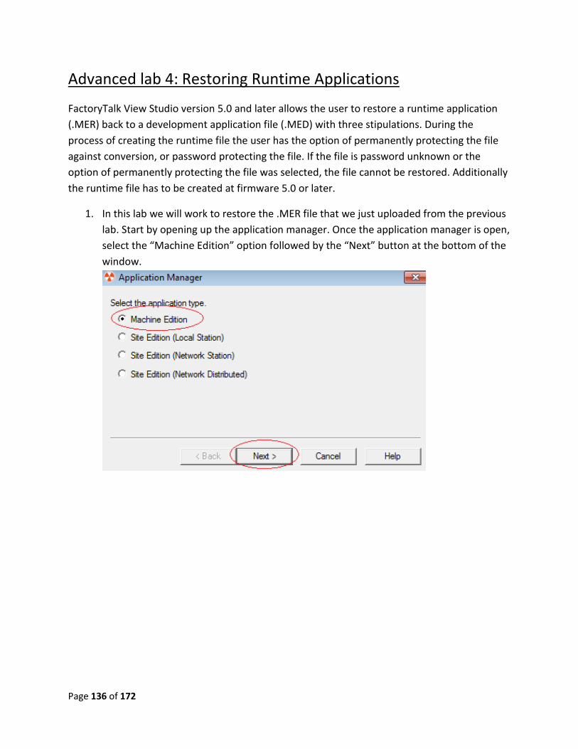
1. In this lab we will work to restore the .MER file that we just uploaded from the previous
lab. Start by opening up the application manager. Once the application manager is open,
select the “Machine Edition” option followed by the “Next” button at the bottom of the
window.
Page 137 of 172
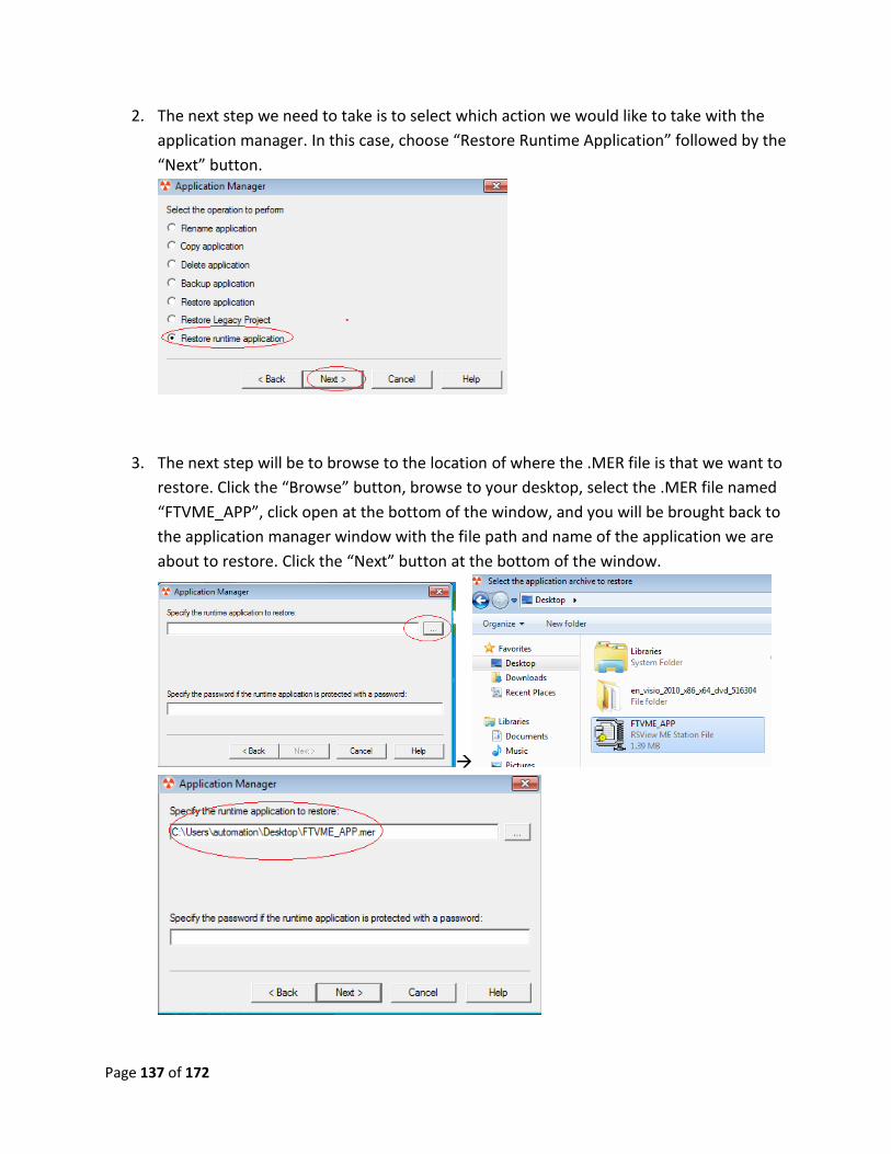
2. The next step we need to take is to select which action we would like to take with the
application manager. In this case, choose “Restore Runtime Application” followed by the
“Next” button.
3. The next step will be to browse to the location of where the .MER file is that we want to
restore. Click the “Browse” button, browse to your desktop, select the .MER file named
“FTVME_APP”, click open at the bottom of the window, and you will be brought back to
the application manager window with the file path and name of the application we are
about to restore. Click the “Next” button at the bottom of the window.
Page 138 of 172
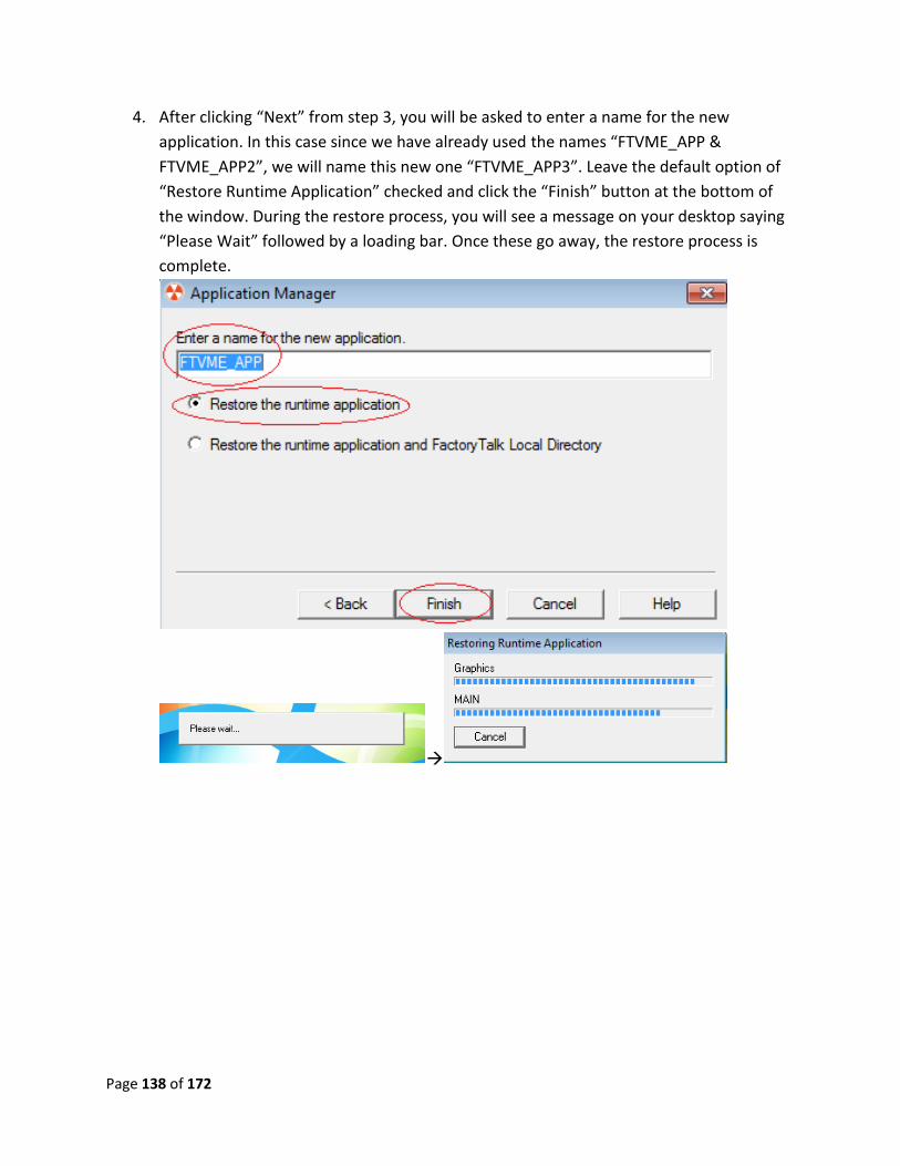
4. After clicking “Next” from step 3, you will be asked to enter a name for the new
application. In this case since we have already used the names “FTVME_APP &
FTVME_APP2”, we will name this new one “FTVME_APP3”. Leave the default option of
“Restore Runtime Application” checked and click the “Finish” button at the bottom of
the window. During the restore process, you will see a message on your desktop saying
“Please Wait” followed by a loading bar. Once these go away, the restore process is
complete.
Page 139 of 172
Advanced Lab 4 Review:
1. Name two of the three reasons why you cannot restore a runtime file?
2. What version of FactoryTalk View Studio and later allows the user to restore runtime
applications?
3. What is the purpose of restoring a runtime file?
This now completes advanced lab 4. Please wait for instructions to proceed further.
Page 140 of 172
Advanced lab 5: Resizing the display
This lab is for demonstration purposes. Downloading the wrong size display could lead to
unexpected results. Consult your user manual and part number of your PanelView before
changing the project window size.
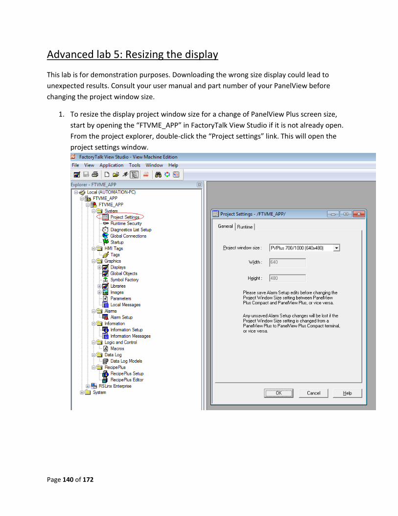
1. To resize the display project window size for a change of PanelView Plus screen size,
start by opening the “FTVME_APP” in FactoryTalk View Studio if it is not already open.
From the project explorer, double-click the “Project settings” link. This will open the
project settings window.
Page 141 of 172
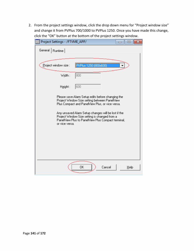
2. From the project settings window, click the drop down menu for “Project window size”
and change it from PVPlus 700/1000 to PVPlus 1250. Once you have made this change,
click the “OK” button at the bottom of the project settings window.
Page 142 of 172
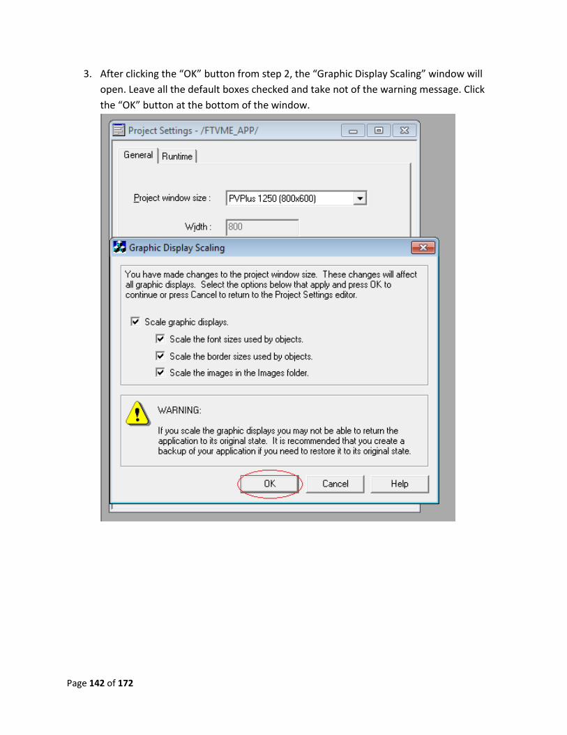
3. After clicking the “OK” button from step 2, the “Graphic Display Scaling” window will
open. Leave all the default boxes checked and take not of the warning message. Click
the “OK” button at the bottom of the window.
Page 143 of 172
4. After clicking “OK” from step 3, a brief loading bar will appear and then all the windows
will close. Open up one of your displays and note the size change of the display itself
and all the objects.
5. After changing the screen resolution in step 3, change to screen resolution back to
“PVPlus 700/1000 (640x480) so that we can move on to the next lab.
Page 144 of 172
Advance Lab 5 review:
1. What other changes can you make to your program from the project settings menu?
2. When making changes to your display resolution, would you ever have to worry about
the scaling of graphics?
This now completes advanced lab 5. Please wait for instructions to proceed further.
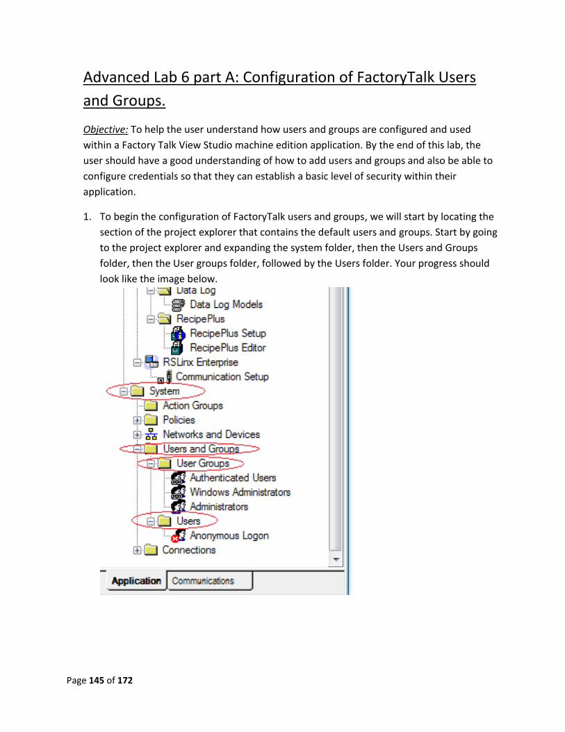
Page 145 of 172
Advanced Lab 6 part A: Configuration of FactoryTalk Users
and Groups.
Objective: To help the user understand how users and groups are configured and used
within a Factory Talk View Studio machine edition application. By the end of this lab, the
user should have a good understanding of how to add users and groups and also be able to
configure credentials so that they can establish a basic level of security within their
application.
1. To begin the configuration of FactoryTalk users and groups, we will start by locating the
section of the project explorer that contains the default users and groups. Start by going
to the project explorer and expanding the system folder, then the Users and Groups
folder, then the User groups folder, followed by the Users folder. Your progress should
look like the image below.
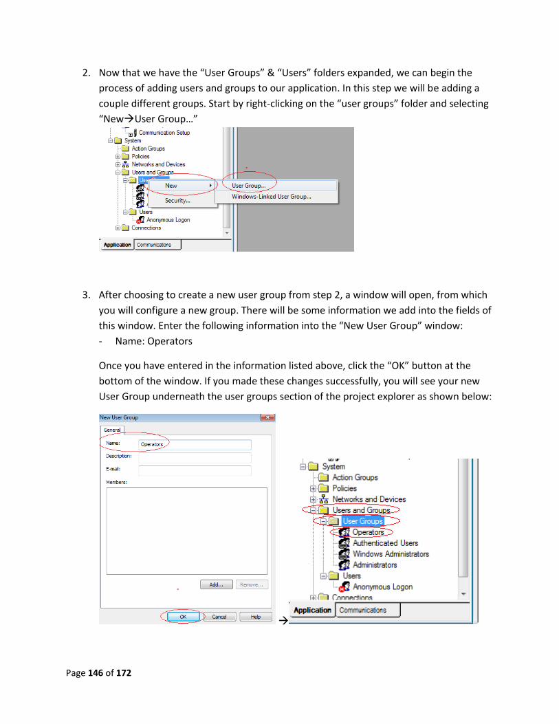
Page 146 of 172
2. Now that we have the “User Groups” & “Users” folders expanded, we can begin the
process of adding users and groups to our application. In this step we will be adding a
couple different groups. Start by right-clicking on the “user groups” folder and selecting
“NewUser Group…”
3. After choosing to create a new user group from step 2, a window will open, from which
you will configure a new group. There will be some information we add into the fields of
this window. Enter the following information into the “New User Group” window:
- Name: Operators
Once you have entered in the information listed above, click the “OK” button at the
bottom of the window. If you made these changes successfully, you will see your new
User Group underneath the user groups section of the project explorer as shown below:
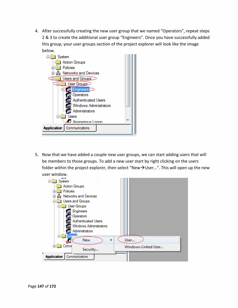
Page 147 of 172
4. After successfully creating the new user group that we named “Operators”, repeat steps
2 & 3 to create the additional user group “Engineers”. Once you have successfully added
this group, your user groups section of the project explorer will look like the image
below.
5. Now that we have added a couple new user groups, we can start adding users that will
be members to those groups. To add a new user start by right clicking on the users
folder within the project explorer, then select “NewUser…”. This will open up the new
user window.
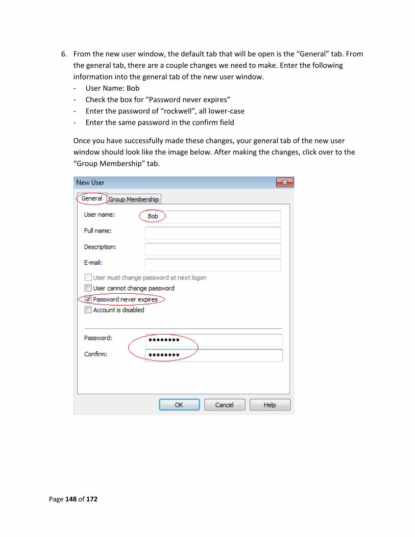
Page 148 of 172
6. From the new user window, the default tab that will be open is the “General” tab. From
the general tab, there are a couple changes we need to make. Enter the following
information into the general tab of the new user window.
- User Name: Bob
- Check the box for “Password never expires”
- Enter the password of “rockwell”, all lower-case
- Enter the same password in the confirm field
Once you have successfully made these changes, your general tab of the new user
window should look like the image below. After making the changes, click over to the
“Group Membership” tab.
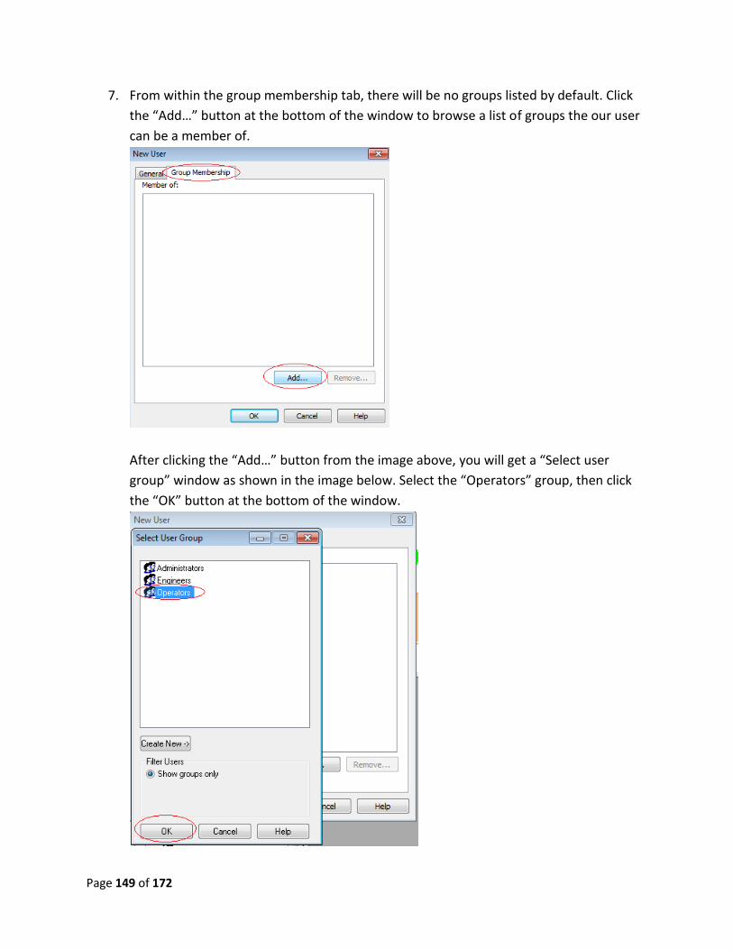
Page 149 of 172
7. From within the group membership tab, there will be no groups listed by default. Click
the “Add…” button at the bottom of the window to browse a list of groups the our user
can be a member of.
After clicking the “Add…” button from the image above, you will get a “Select user
group” window as shown in the image below. Select the “Operators” group, then click
the “OK” button at the bottom of the window.
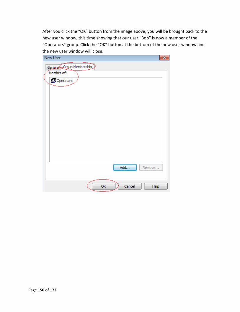
Page 150 of 172
After you click the “OK” button from the image above, you will be brought back to the
new user window, this time showing that our user “Bob” is now a member of the
“Operators” group. Click the “OK” button at the bottom of the new user window and
the new user window will close.
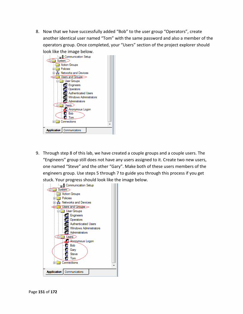
Page 151 of 172
8. Now that we have successfully added “Bob” to the user group “Operators”, create
another identical user named “Tom” with the same password and also a member of the
operators group. Once completed, your “Users” section of the project explorer should
look like the image below.
9. Through step 8 of this lab, we have created a couple groups and a couple users. The
“Engineers” group still does not have any users assigned to it. Create two new users,
one named “Steve” and the other “Gary”. Make both of these users members of the
engineers group. Use steps 5 through 7 to guide you through this process if you get
stuck. Your progress should look like the image below.
Page 152 of 172
Advanced lab 6 review:
1. Where would I configure settings so that a user’s password has to be changed upon first
log in?
2. Can Windows user accounts be linked in to our FactoryTalk application?
3. Can a user be part of more than 1 group at a time?
This now completes advanced lab 6 part A. Please wait for instructions to proceed further.
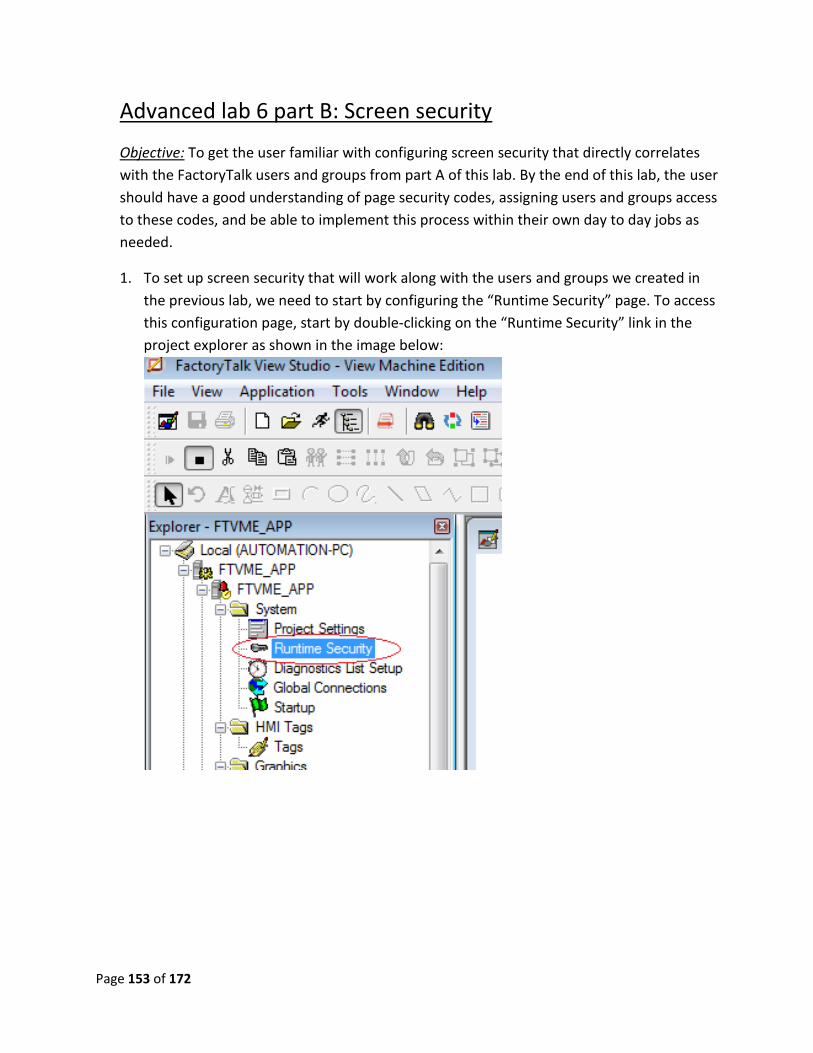
Page 153 of 172
Advanced lab 6 part B: Screen security
Objective: To get the user familiar with configuring screen security that directly correlates
with the FactoryTalk users and groups from part A of this lab. By the end of this lab, the user
should have a good understanding of page security codes, assigning users and groups access
to these codes, and be able to implement this process within their own day to day jobs as
needed.
1. To set up screen security that will work along with the users and groups we created in
the previous lab, we need to start by configuring the “Runtime Security” page. To access
this configuration page, start by double-clicking on the “Runtime Security” link in the
project explorer as shown in the image below:
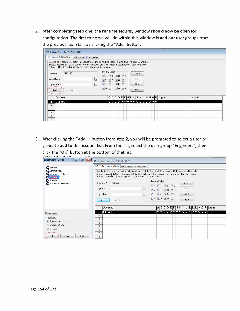
Page 154 of 172
2. After completing step one, the runtime security window should now be open for
configuration. The first thing we will do within this window is add our user groups from
the previous lab. Start by clicking the “Add” button.
3. After clicking the “Add…” button from step 2, you will be prompted to select a user or
group to add to the account list. From the list, select the user group “Engineers”, then
click the “OK” button at the bottom of that list.
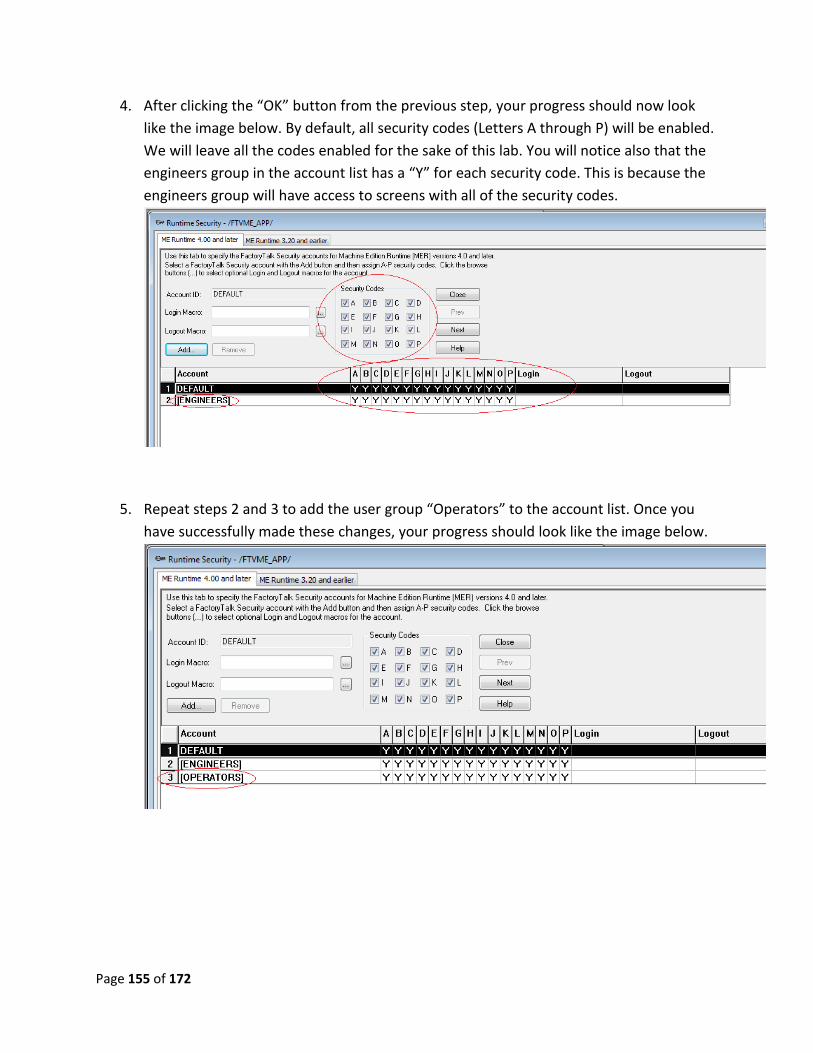
Page 155 of 172
4. After clicking the “OK” button from the previous step, your progress should now look
like the image below. By default, all security codes (Letters A through P) will be enabled.
We will leave all the codes enabled for the sake of this lab. You will notice also that the
engineers group in the account list has a “Y” for each security code. This is because the
engineers group will have access to screens with all of the security codes.
5. Repeat steps 2 and 3 to add the user group “Operators” to the account list. Once you
have successfully made these changes, your progress should look like the image below.
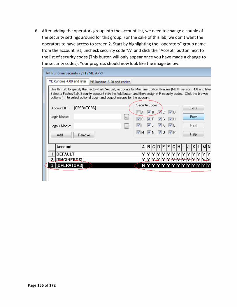
Page 156 of 172
6. After adding the operators group into the account list, we need to change a couple of
the security settings around for this group. For the sake of this lab, we don’t want the
operators to have access to screen 2. Start by highlighting the “operators” group name
from the account list, uncheck security code “A” and click the “Accept” button next to
the list of security codes (This button will only appear once you have made a change to
the security codes). Your progress should now look like the image below.
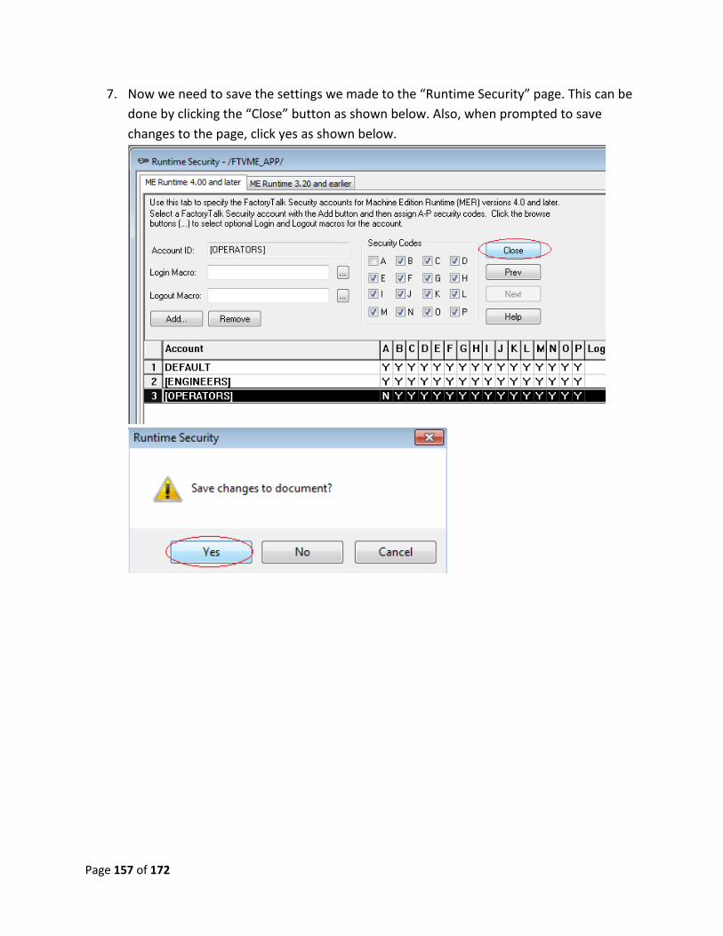
Page 157 of 172
7. Now we need to save the settings we made to the “Runtime Security” page. This can be
done by clicking the “Close” button as shown below. Also, when prompted to save
changes to the page, click yes as shown below.
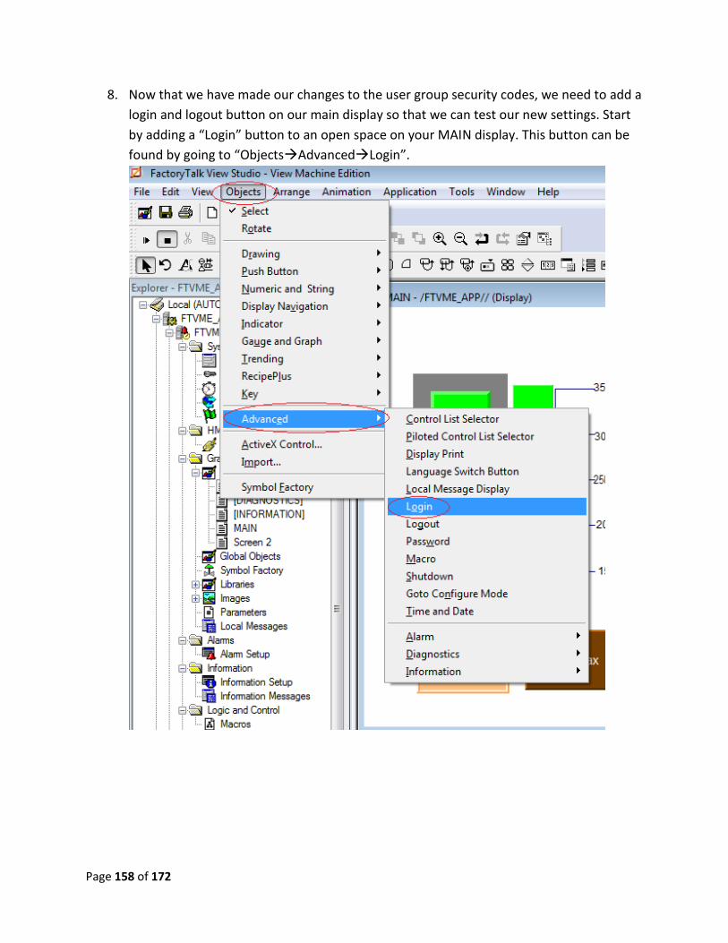
Page 158 of 172
8. Now that we have made our changes to the user group security codes, we need to add a
login and logout button on our main display so that we can test our new settings. Start
by adding a “Login” button to an open space on your MAIN display. This button can be
found by going to “ObjectsAdvancedLogin”.
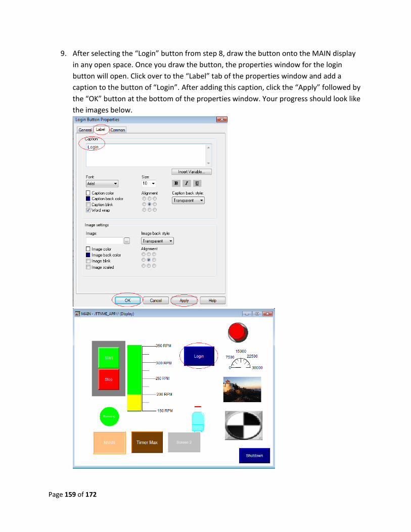
Page 159 of 172
9. After selecting the “Login” button from step 8, draw the button onto the MAIN display
in any open space. Once you draw the button, the properties window for the login
button will open. Click over to the “Label” tab of the properties window and add a
caption to the button of “Login”. After adding this caption, click the “Apply” followed by
the “OK” button at the bottom of the properties window. Your progress should look like
the images below.
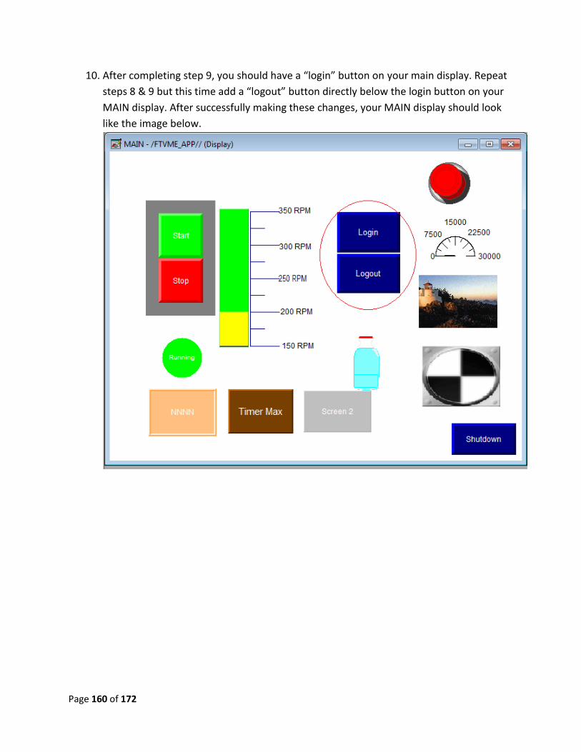
Page 160 of 172
10. After completing step 9, you should have a “login” button on your main display. Repeat
steps 8 & 9 but this time add a “logout” button directly below the login button on your
MAIN display. After successfully making these changes, your MAIN display should look
like the image below.
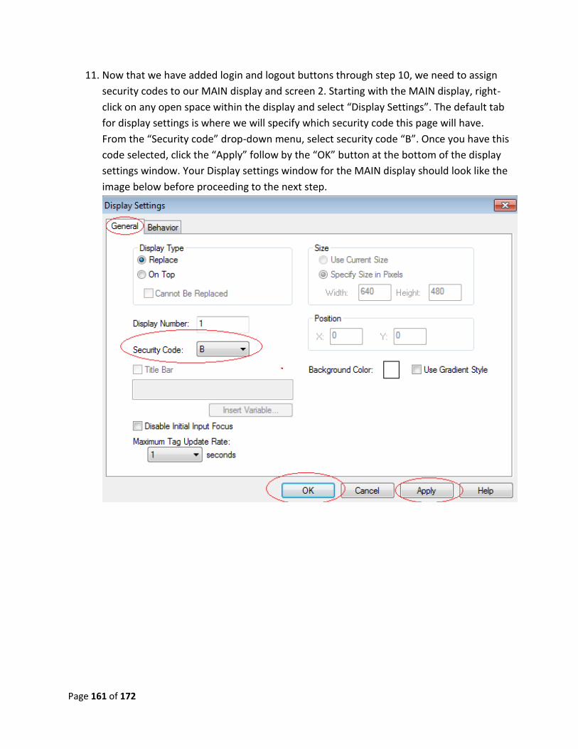
Page 161 of 172
11. Now that we have added login and logout buttons through step 10, we need to assign
security codes to our MAIN display and screen 2. Starting with the MAIN display, right-
click on any open space within the display and select “Display Settings”. The default tab
for display settings is where we will specify which security code this page will have.
From the “Security code” drop-down menu, select security code “B”. Once you have this
code selected, click the “Apply” follow by the “OK” button at the bottom of the display
settings window. Your Display settings window for the MAIN display should look like the
image below before proceeding to the next step.
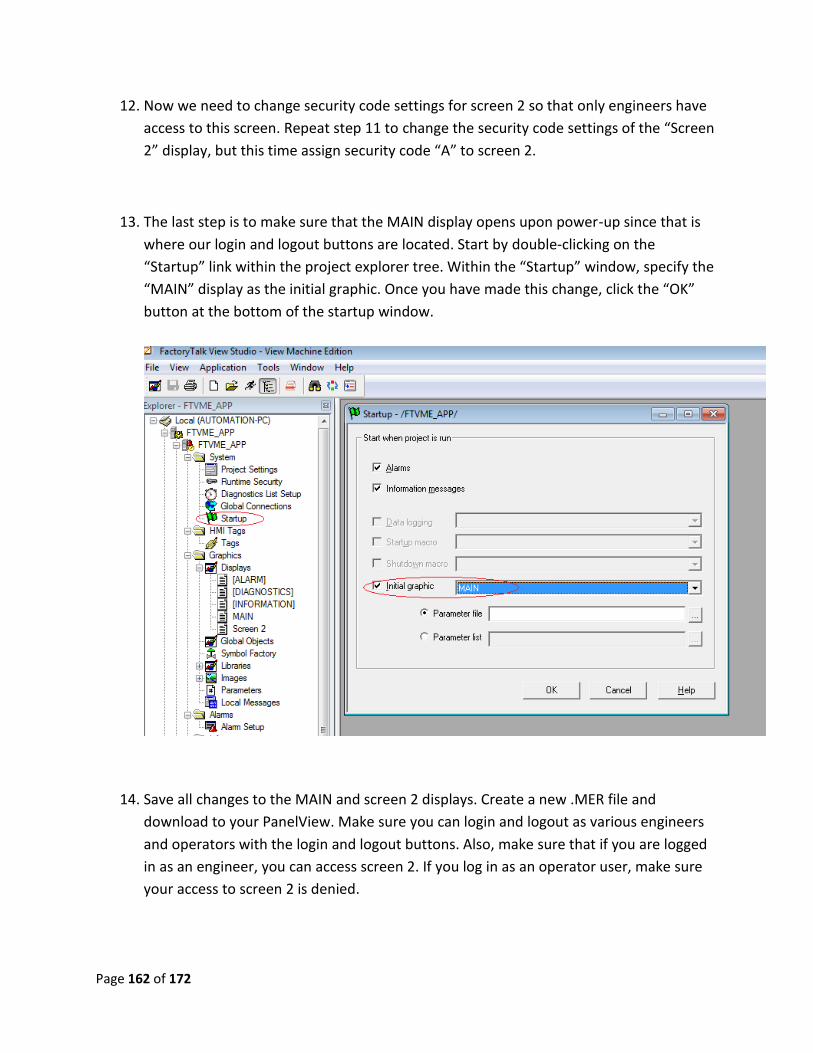
Page 162 of 172
12. Now we need to change security code settings for screen 2 so that only engineers have
access to this screen. Repeat step 11 to change the security code settings of the “Screen
2” display, but this time assign security code “A” to screen 2.
13. The last step is to make sure that the MAIN display opens upon power-up since that is
where our login and logout buttons are located. Start by double-clicking on the
“Startup” link within the project explorer tree. Within the “Startup” window, specify the
“MAIN” display as the initial graphic. Once you have made this change, click the “OK”
button at the bottom of the startup window.
14. Save all changes to the MAIN and screen 2 displays. Create a new .MER file and
download to your PanelView. Make sure you can login and logout as various engineers
and operators with the login and logout buttons. Also, make sure that if you are logged
in as an engineer, you can access screen 2. If you log in as an operator user, make sure
your access to screen 2 is denied.
Page 163 of 172
Advanced lab 6 part B review:
1. What would be another way to log different users in, other than a login / logout button?
2. Can I specify security code security at an individual user level?
3. If I wanted a macro to run for a given login, where would that be configured?
This now completes advanced lab 6 part B. please wait for instructions to proceed further.
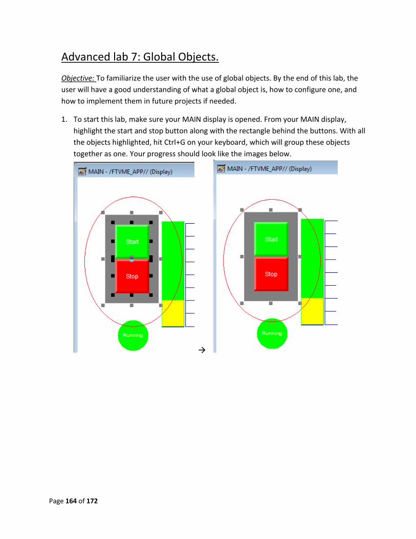
Page 164 of 172
Advanced lab 7: Global Objects.
Objective: To familiarize the user with the use of global objects. By the end of this lab, the
user will have a good understanding of what a global object is, how to configure one, and
how to implement them in future projects if needed.
1. To start this lab, make sure your MAIN display is opened. From your MAIN display,
highlight the start and stop button along with the rectangle behind the buttons. With all
the objects highlighted, hit Ctrl+G on your keyboard, which will group these objects
together as one. Your progress should look like the images below.
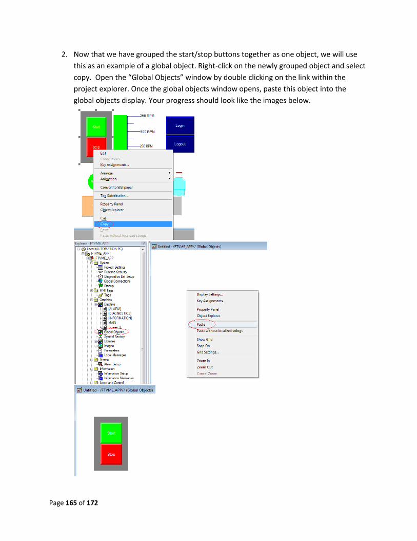
Page 165 of 172
2. Now that we have grouped the start/stop buttons together as one object, we will use
this as an example of a global object. Right-click on the newly grouped object and select
copy. Open the “Global Objects” window by double clicking on the link within the
project explorer. Once the global objects window opens, paste this object into the
global objects display. Your progress should look like the images below.
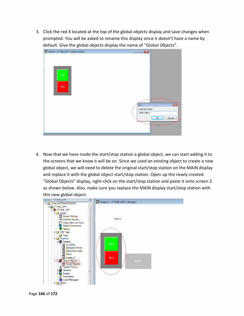
Page 166 of 172
3. Click the red X located at the top of the global objects display and save changes when
prompted. You will be asked to rename this display since it doesn’t have a name by
default. Give the global objects display the name of “Global Objects”.
4. Now that we have made the start/stop station a global object, we can start adding it to
the screens that we know it will be on. Since we used an existing object to create a new
global object, we will need to delete the original start/stop station on the MAIN display
and replace it with the global object start/stop station. Open up the newly created
“Global Objects” display, right-click on the start/stop station and paste it onto screen 2
as shown below. Also, make sure you replace the MAIN display start/stop station with
this new global object.
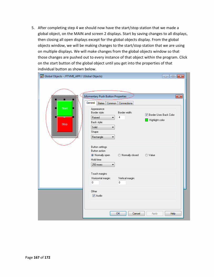
Page 167 of 172
5. After completing step 4 we should now have the start/stop station that we made a
global object, on the MAIN and screen 2 displays. Start by saving changes to all displays,
then closing all open displays except for the global objects display. From the global
objects window, we will be making changes to the start/stop station that we are using
on multiple displays. We will make changes from the global objects window so that
those changes are pushed out to every instance of that object within the program. Click
on the start button of the global object until you get into the properties of that
individual button as shown below.
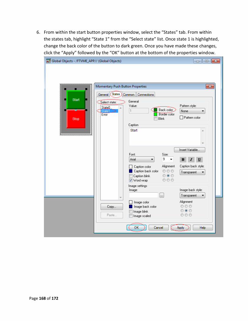
Page 168 of 172
6. From within the start button properties window, select the “States” tab. From within
the states tab, highlight “State 1” from the “Select state” list. Once state 1 is highlighted,
change the back color of the button to dark green. Once you have made these changes,
click the “Apply” followed by the “OK” button at the bottom of the properties window.
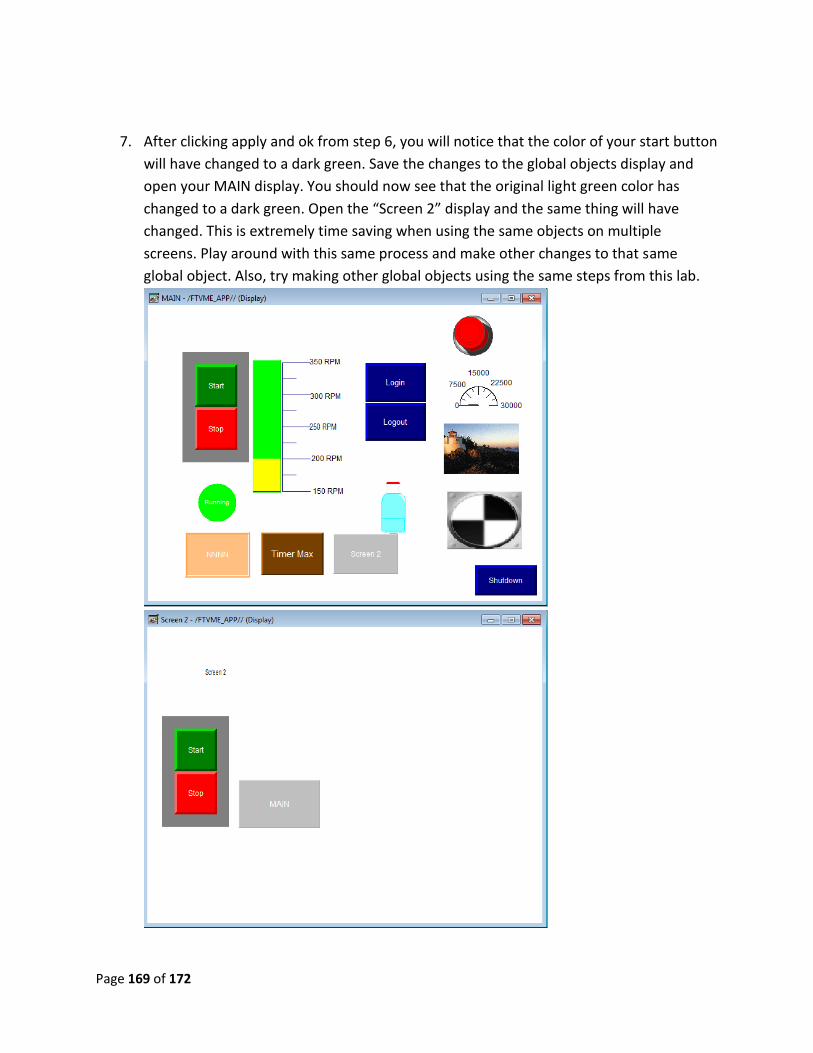
Page 169 of 172
7. After clicking apply and ok from step 6, you will notice that the color of your start button
will have changed to a dark green. Save the changes to the global objects display and
open your MAIN display. You should now see that the original light green color has
changed to a dark green. Open the “Screen 2” display and the same thing will have
changed. This is extremely time saving when using the same objects on multiple
screens. Play around with this same process and make other changes to that same
global object. Also, try making other global objects using the same steps from this lab.
Page 170 of 172
Advanced lab 7 review:
1. Why is using something like global objects useful?
2. What are the hot-keys for grouping and un-grouping objects?
3. What is the process for making a global object?
This now completes advanced lab 7. Please wait for instructions to proceed further.
Page 171 of 172
Appendix A
Helpful Links:
Werner Electric’s Website: All things Werner electric. Find contact information,
product lines, place orders and much more! http://www.wernermn.com/
Rockwell Automation Knowledgebase: Find technical notes from cases that
have been solved by Rockwell support engineers.
https://rockwellautomation.custhelp.com/
Rockwell automation’s support page: Find software downloads, firmware
updates, AOP’s, anything to be downloaded from Rockwell Automation
http://www.rockwellautomation.com/rockwellautomation/support/overview.
page?
Rockwell automation literature library: Find all published documents from
Rockwell including user manuals, technical data, product profiles, etc.
http://literature.rockwellautomation.com/idc/groups/public/documents/web
assets/browse_category.hcst
Rockwell automation product drawings / schematics: find CAD drawings and
dimensions for all Rockwell products.
http://www.rockwellautomation.com/rockwellautomation/support/selection.
page

Page 172 of 172
Notes: