Embed Size (px)
Citation preview
Introduction to OSPFISP Training Workshops
1
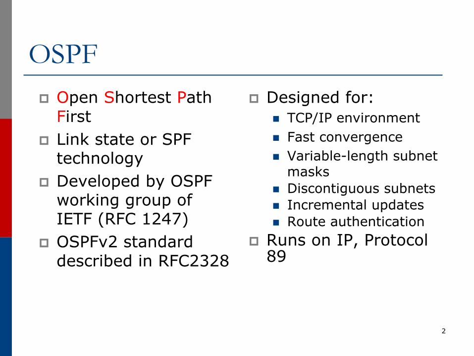
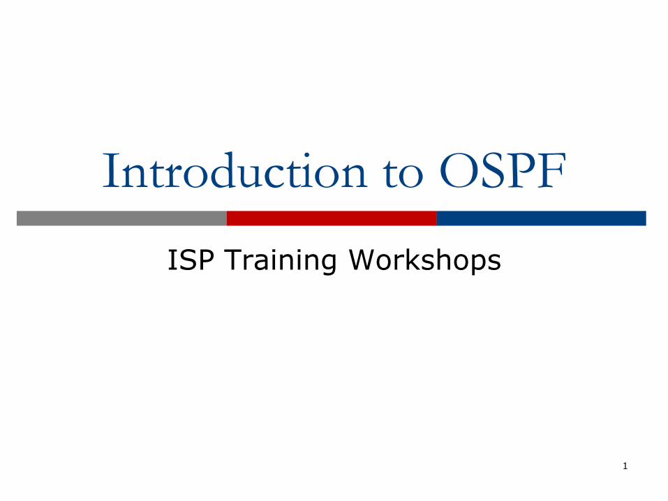
OSPFp Open Shortest Path
Firstp Link state or SPF
technologyp Developed by OSPF
working group of IETF (RFC 1247)
p OSPFv2 standard described in RFC2328
p Designed for:n TCP/IP environmentn Fast convergencen Variable-length subnet
masksn Discontiguous subnetsn Incremental updatesn Route authentication
p Runs on IP, Protocol 89
2
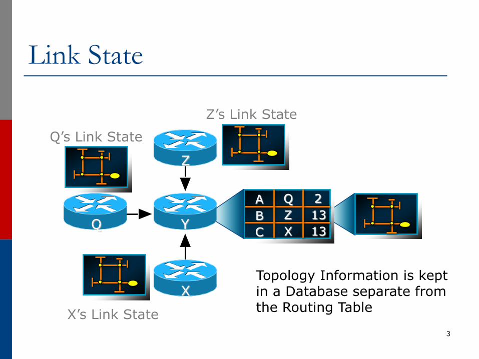
Link State
3
Topology Information is kept in a Database separate from the Routing Table
ABC
21313
QZX
Z
X
YQ
Z’s Link StateQ’s Link State
X’s Link State
Link State Routingp Neighbour discoveryp Constructing a Link State Packet (LSP)p Distribute the LSP
n (Link State Announcement – LSA)
p Compute routesp On network failure
n New LSPs floodedn All routers recompute routing table
4
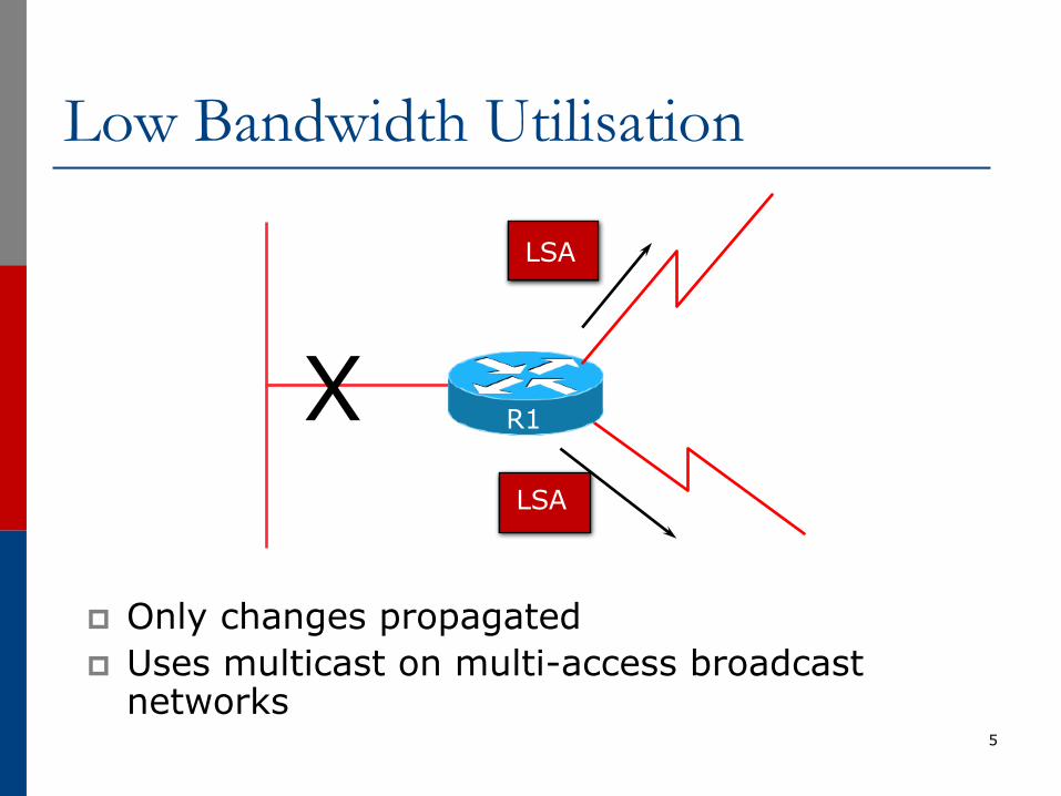
Low Bandwidth Utilisation
p Only changes propagatedp Uses multicast on multi-access broadcast
networks5
LSA
X
LSA
R1
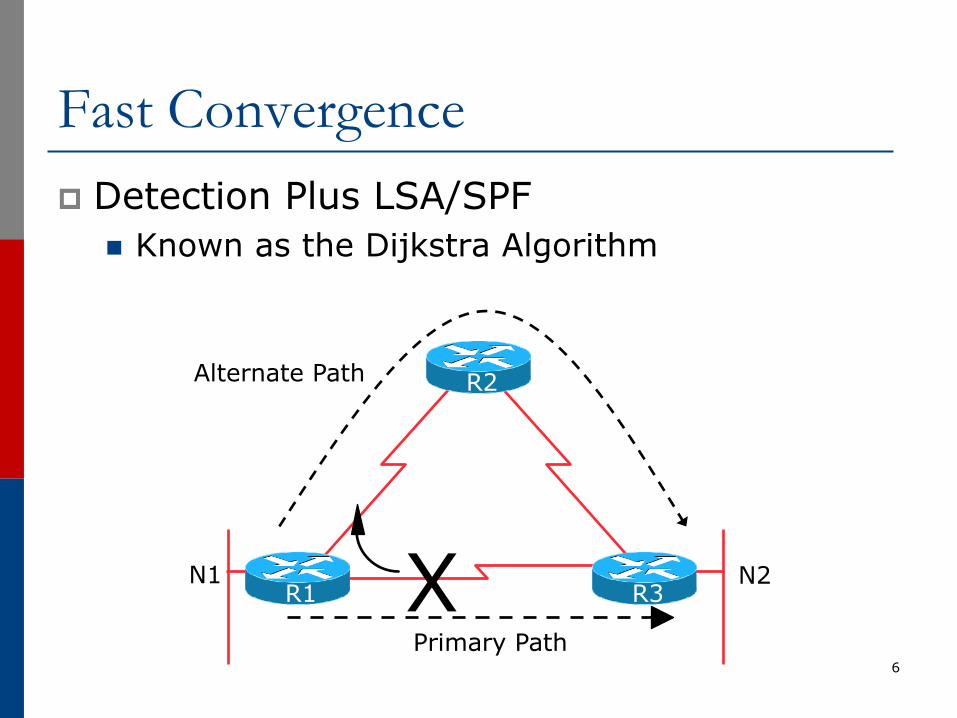
Fast Convergencep Detection Plus LSA/SPF
n Known as the Dijkstra Algorithm
6
X N2
Alternate Path
Primary Path
N1
R2
R1 R3
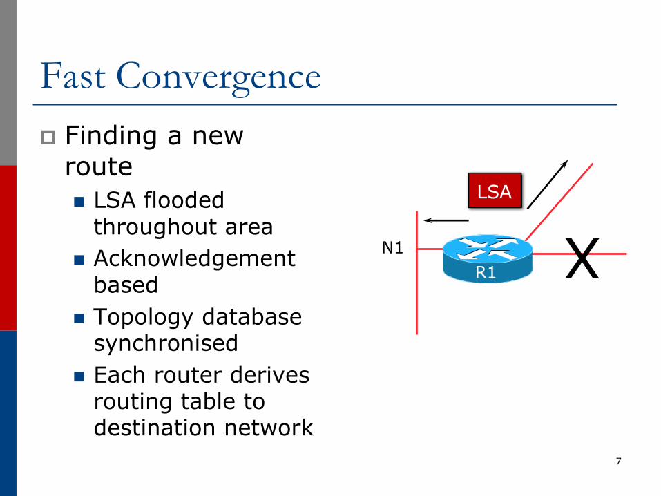
Fast Convergencep Finding a new
routen LSA flooded
throughout arean Acknowledgement
basedn Topology database
synchronisedn Each router derives
routing table to destination network
7
LSA
N1R1 X
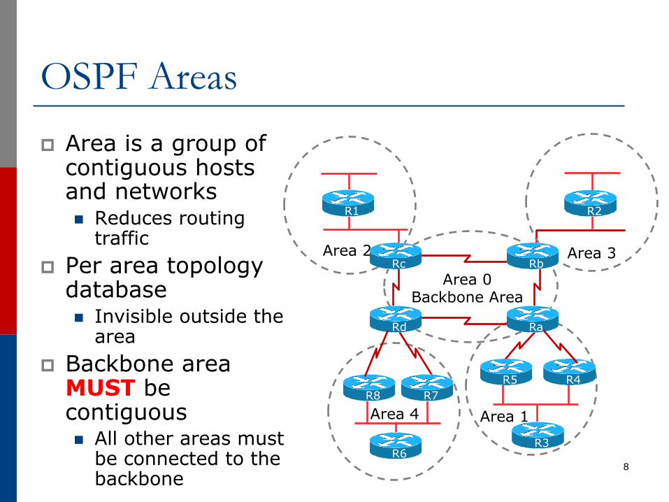
OSPF Areasp Area is a group of
contiguous hosts and networksn Reduces routing
trafficp Per area topology
databasen Invisible outside the
areap Backbone area
MUST be contiguousn All other areas must
be connected to the backbone
8
Area 1
Area 2 Area 3
R1 R2
R3R6
Area 4
R5 R4R7R8
RaRd
RbRcArea 0
Backbone Area
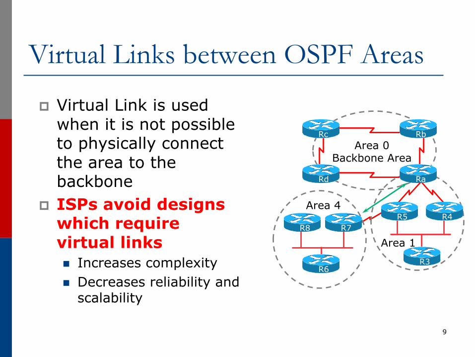
Virtual Links between OSPF Areas
p Virtual Link is used when it is not possible to physically connect the area to the backbone
p ISPs avoid designs which require virtual linksn Increases complexityn Decreases reliability and
scalability
9
Area 1R3
R6
Area 4R5 R4
R7R8
RaRd
RbRcArea 0
Backbone Area
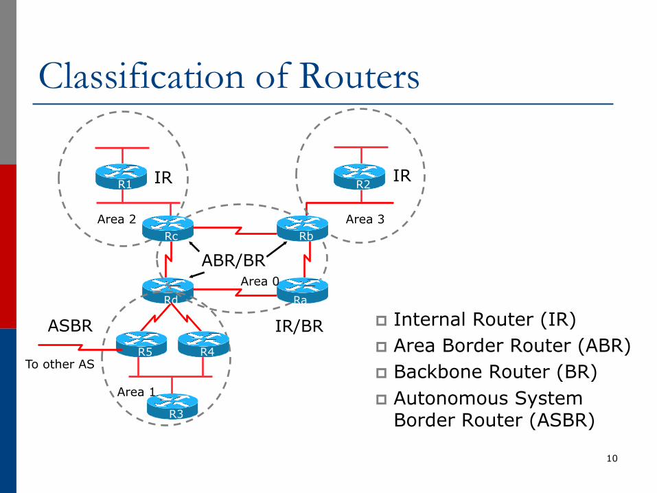
Classification of Routers
p Internal Router (IR)p Area Border Router (ABR)p Backbone Router (BR)p Autonomous System
Border Router (ASBR)
10
R1 R2
R3
R5 R4
Rd Ra
RbRc
IR
ABR/BR
IR/BRASBR
To other AS
IR
Area 1
Area 0
Area 2 Area 3
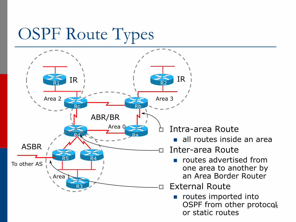
OSPF Route Types
p Intra-area Routen all routes inside an area
p Inter-area Routen routes advertised from
one area to another by an Area Border Router
p External Routen routes imported into
OSPF from other protocol or static routes
11
R1 R2
R3
R5 R4
Rd Ra
RbRc
IR
ABR/BR
ASBR
To other AS
IR
Area 1
Area 0
Area 2 Area 3
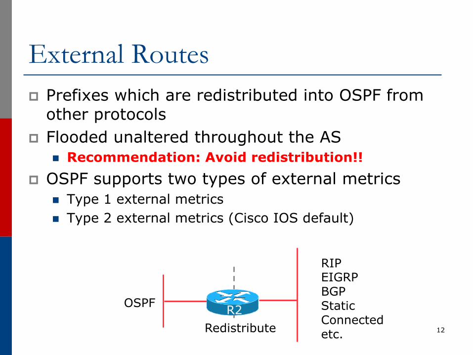
External Routesp Prefixes which are redistributed into OSPF from
other protocolsp Flooded unaltered throughout the AS
n Recommendation: Avoid redistribution!!p OSPF supports two types of external metrics
n Type 1 external metricsn Type 2 external metrics (Cisco IOS default)
12
RIPEIGRPBGPStaticConnectedetc.
OSPF
RedistributeR2
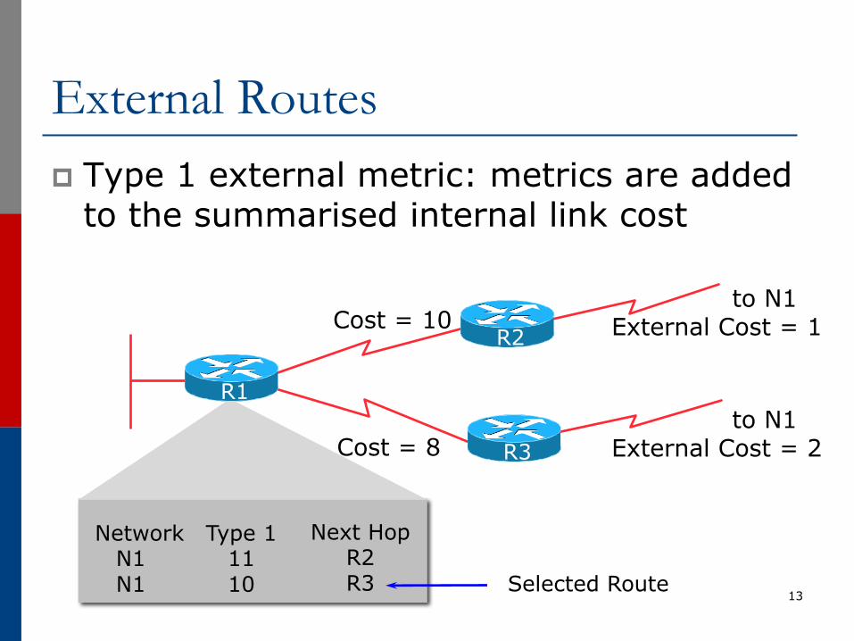
External Routesp Type 1 external metric: metrics are added
to the summarised internal link cost
13
NetworkN1N1
Type 11110
Next HopR2R3
Cost = 10to N1
External Cost = 1
to N1 External Cost = 2Cost = 8
Selected Route
R3
R1
R2
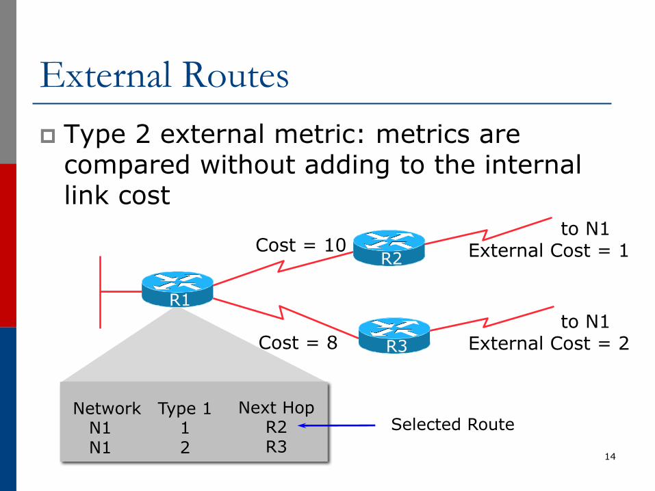
External Routesp Type 2 external metric: metrics are
compared without adding to the internal link cost
14
Cost = 10to N1
External Cost = 1
to N1 External Cost = 2Cost = 8
Selected Route
R3
R1
R2
NetworkN1N1
Type 112
Next HopR2R3
Topology/Link State Databasep A router has a separate LS database for each
area to which it belongsp All routers belonging to the same area have
identical databasep SPF calculation is performed separately for each
areap LSA flooding is bounded by areap Recommendation:
n Limit the number of areas a router participates in!!n 1 to 3 is fine (typical ISP design)n >3 can overload the CPU depending on the area
topology complexity
15
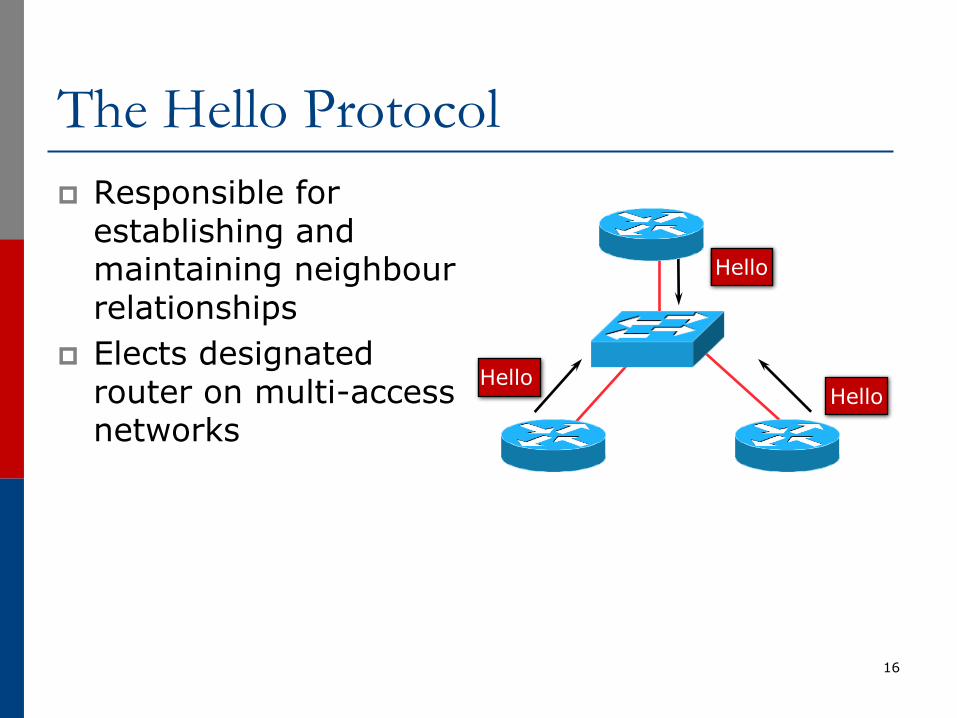
The Hello Protocolp Responsible for
establishing and maintaining neighbour relationships
p Elects designated router on multi-access networks
16
Hello
HelloHello
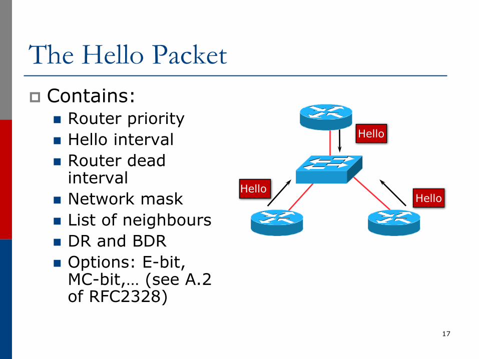
The Hello Packetp Contains:
n Router priorityn Hello interval n Router dead
intervaln Network maskn List of neighboursn DR and BDRn Options: E-bit,
MC-bit,… (see A.2 of RFC2328)
17
Hello
HelloHello
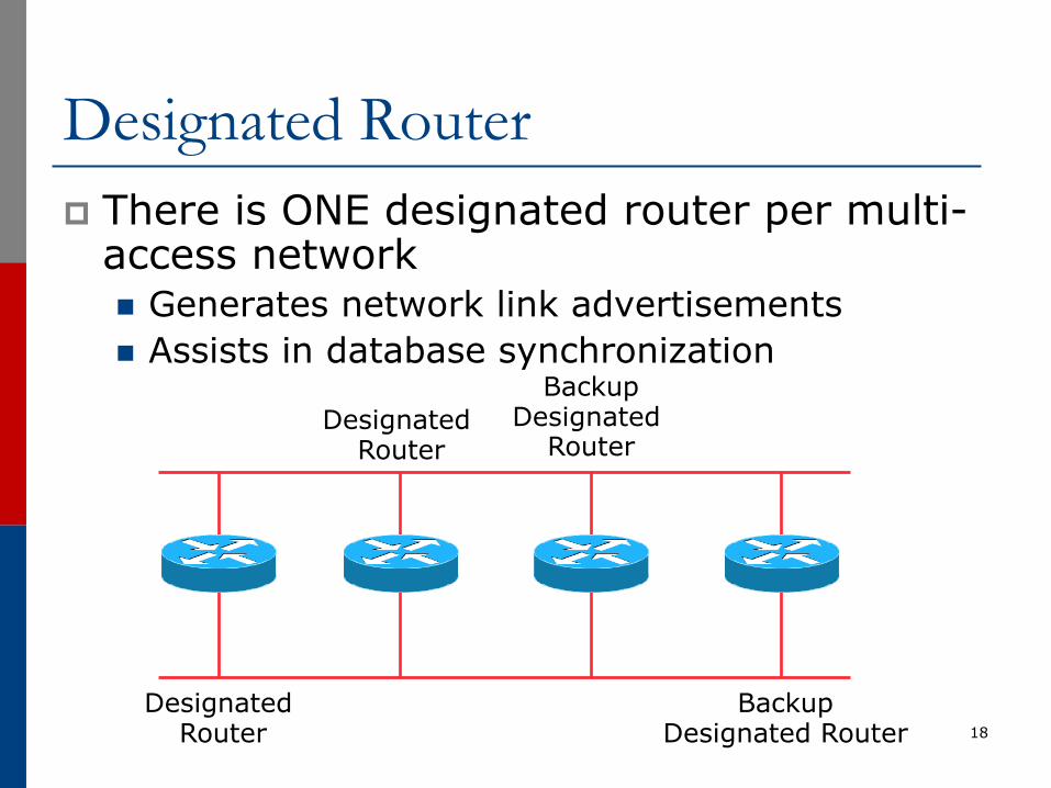
Designated Routerp There is ONE designated router per multi-
access networkn Generates network link advertisementsn Assists in database synchronization
18
Designated Router
Designated Router
BackupDesignated Router
BackupDesignated
Router
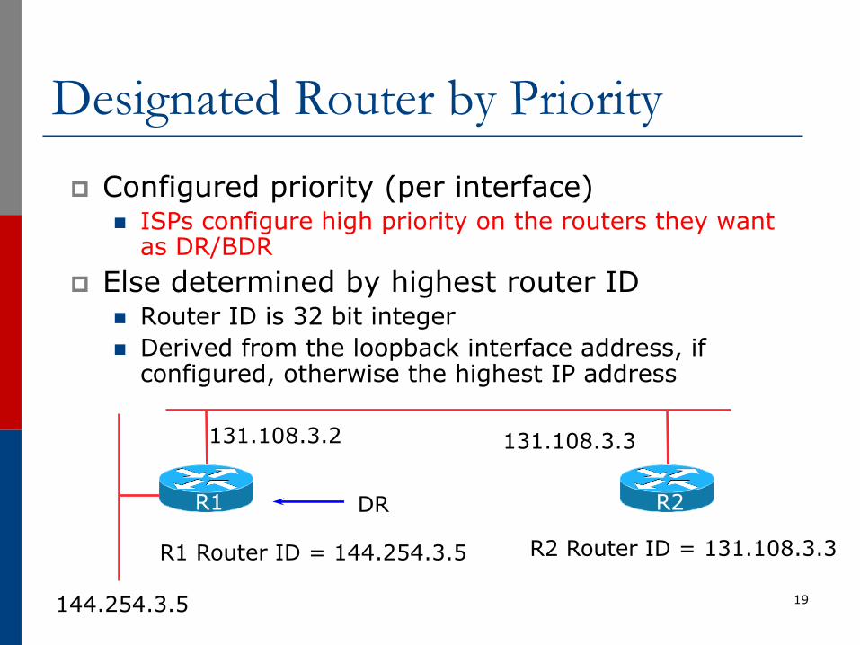
Designated Router by Priorityp Configured priority (per interface)
n ISPs configure high priority on the routers they want as DR/BDR
p Else determined by highest router IDn Router ID is 32 bit integern Derived from the loopback interface address, if
configured, otherwise the highest IP address
19144.254.3.5
R2 Router ID = 131.108.3.3
131.108.3.2 131.108.3.3
R1 Router ID = 144.254.3.5
DR R2R1
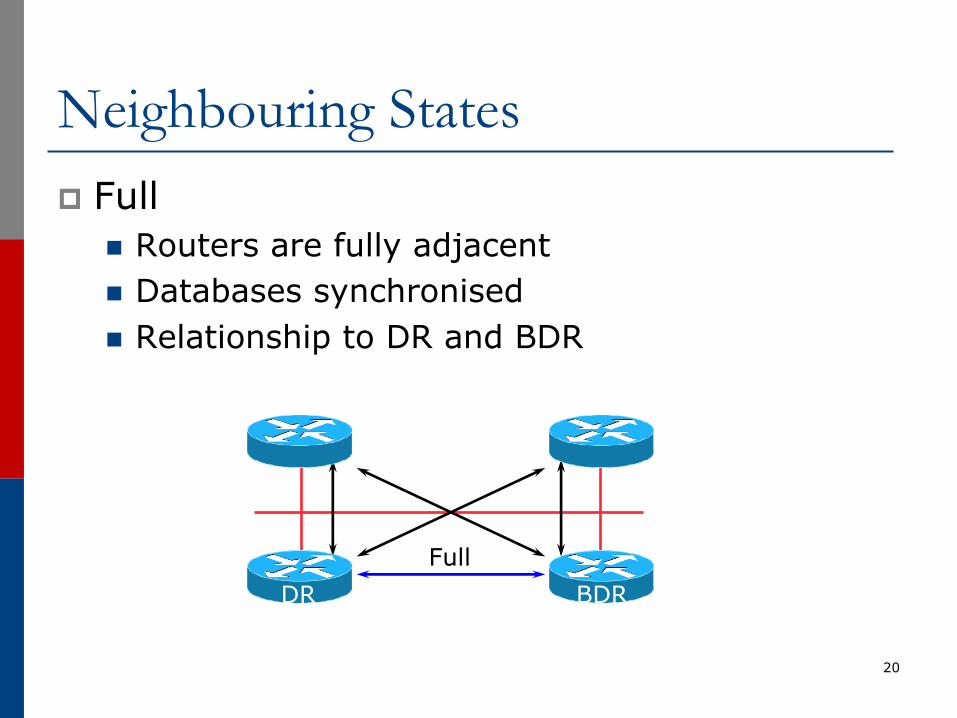
Neighbouring Statesp Full
n Routers are fully adjacentn Databases synchronisedn Relationship to DR and BDR
20
FullDR BDR
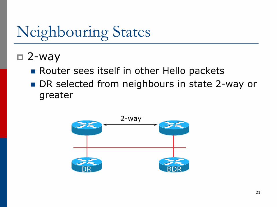
Neighbouring Statesp 2-way
n Router sees itself in other Hello packetsn DR selected from neighbours in state 2-way or
greater
21
2-way
DR BDR
When to Become Adjacentp Underlying network is point to pointp Underlying network type is virtual linkp The router itself is the designated router
or the backup designated routerp The neighbouring router is the designated
router or the backup designated router
22
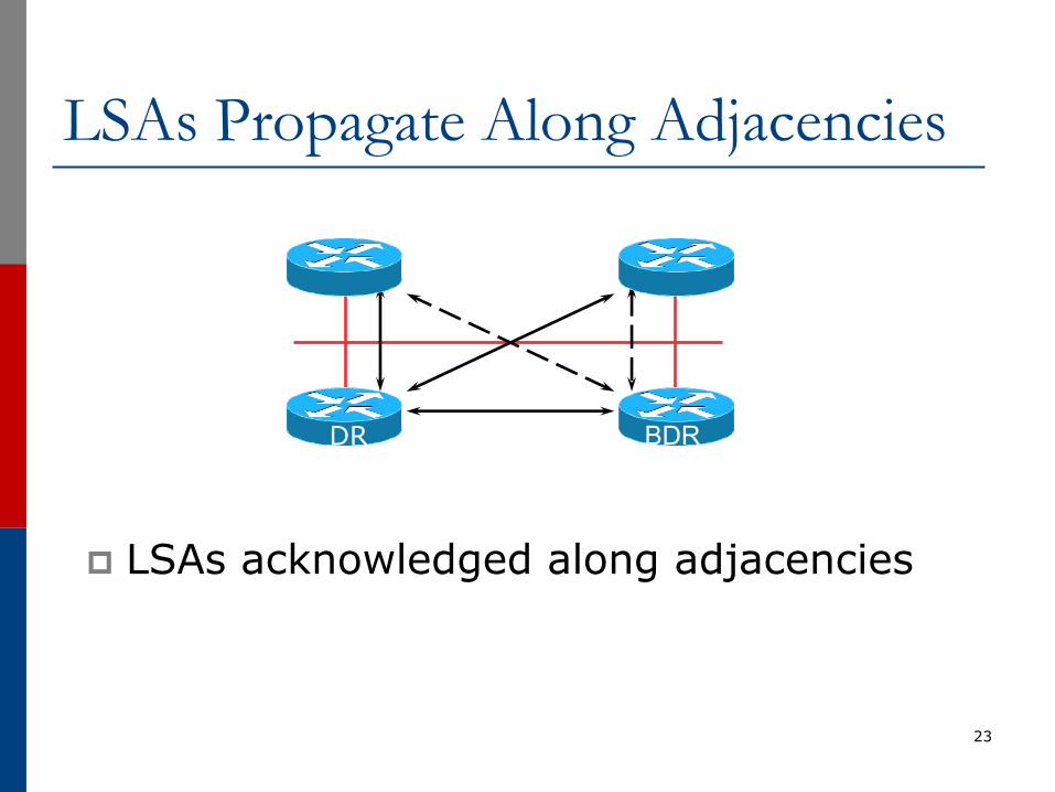
LSAs Propagate Along Adjacencies
p LSAs acknowledged along adjacencies
23
DR BDR
Broadcast Networksp IP Multicast used for Sending and
Receiving Updatesn All routers must accept packets sent to
AllSPFRouters (224.0.0.5)n All DR and BDR routers must accept packets
sent to AllDRouters (224.0.0.6)p Hello packets sent to AllSPFRouters
(Unicast on point-to-point and virtual links)
24
Routing Protocol Packetsp Share a common protocol headerp Routing protocol packets are sent with type of
service (TOS) of 0p Five types of OSPF routing protocol packets
n Hello – packet type 1n Database description – packet type 2n Link-state request – packet type 3n Link-state update – packet type 4n Link-state acknowledgement – packet type 5
25
Different Types of LSAsp Six distinct type of LSAs
n Type 1 : Router LSAn Type 2 : Network LSAn Type 3 & 4: Summary LSAn Type 5 & 7: External LSA (Type 7 is for NSSA)n Type 6: Group membership LSAn Type 9, 10 & 11: Opaque LSA (9: Link-Local, 10: Area)
26
Router LSA (Type 1)p Describes the state and cost of the
router’s links to the areap All of the router’s links in an area must be
described in a single LSAp Flooded throughout the particular area
and no morep Router indicates whether it is an ASBR,
ABR, or end point of virtual link
27
Network LSA (Type 2)p Generated for every transit broadcast and
NBMA networkp Describes all the routers attached to the
networkp Only the designated router originates this
LSAp Flooded throughout the area and no more
28
Summary LSA (Type 3 and 4)p Describes the destination outside the area
but still in the ASp Flooded throughout a single areap Originated by an ABRp Only inter-area routes are advertised into
the backbonep Type 4 is the information about the ASBR
29
External LSA (Type 5 and 7)p Defines routes to destination external to
the ASp Default route is also sent as externalp Two types of external LSA:
n E1: Consider the total cost up to the external destination
n E2: Considers only the cost of the outgoing interface to the external destination
p (Type 7 LSAs used to describe external LSA for one specific OSPF area type)
30
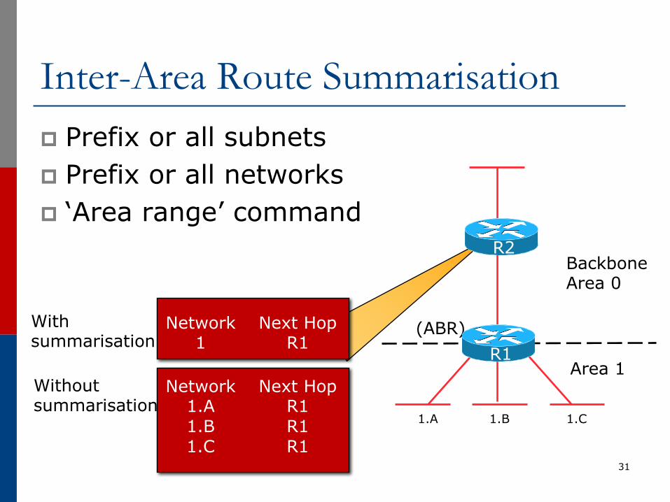
Inter-Area Route Summarisationp Prefix or all subnetsp Prefix or all networksp ‘Area range’ command
31
1.A 1.B 1.C
(ABR)Network1
Next HopR1
Network1.A1.B1.C
Next HopR1R1R1
With summarisation
Withoutsummarisation
BackboneArea 0
Area 1R1
R2

No Summarisationp Specific Link LSA advertised out of each areap Link state changes propagated out of each area
32
3.A3.B
3.C 3.D2.A2.B
2.C 2.D
1.A1.B
1.C 1.D
1.A1.B1.C1.D Area 0
2.A2.B2.C2.D
3.A3.B3.C3.D

With Summarisationp Only summary LSA advertised out of each areap Link state changes do not propagate out of the area
33
3.A3.B
3.C 3.D2.A2.B
2.C 2.D
1.A1.B
1.C 1.D
1Area 0
2
3
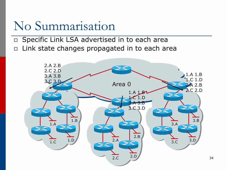
No Summarisationp Specific Link LSA advertised in to each areap Link state changes propagated in to each area
34
3.A3.B
3.C 3.D2.A2.B
2.C 2.D
1.A1.B
1.C 1.D
2.A 2.B2.C 2.D3.A 3.B3.C 3.D Area 0
1.A 1.B1.C 1.D3.A 3.B3.C 3.D
1.A 1.B1.C 1.D2.A 2.B2.C 2.D
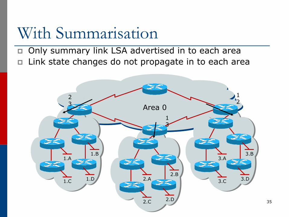
With Summarisationp Only summary link LSA advertised in to each areap Link state changes do not propagate in to each area
35
3.A3.B
3.C 3.D2.A2.B
2.C 2.D
1.A1.B
1.C 1.D
23 Area 0
13
12
Types of Areas
p Regularp Stubp Totally Stubbyp Not-So-Stubbyp Only “regular” areas are useful for ISPs
n Other area types handle redistribution of other routing protocols into OSPF – ISPs don’t redistribute anything into OSPF
p The next slides describing the different area types are provided for information only
36
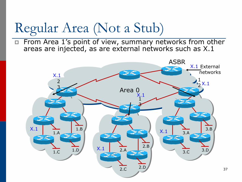
Regular Area (Not a Stub)p From Area 1’s point of view, summary networks from other
areas are injected, as are external networks such as X.1
37
3.A3.B
3.C 3.D2.A2.B
2.C 2.D
1.A1.B
1.C 1.D
23 Area 0
13
12
ASBRExternal networks
X.1
X.1
X.1
X.1
X.1
X.1
X.1
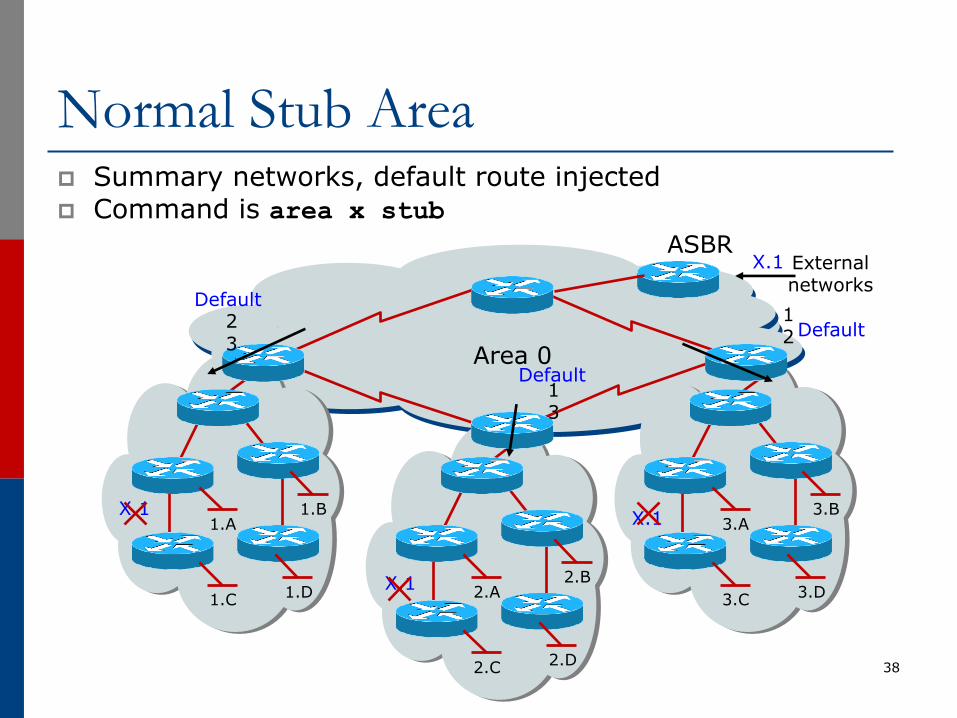
Normal Stub Areap Summary networks, default route injectedp Command is area x stub
38
3.A3.B
3.C 3.D2.A2.B
2.C 2.D
1.A1.B
1.C 1.D
23 Area 0
13
12
ASBRExternal networks
X.1
X.1
Default
X.1
X.1
Default
Default
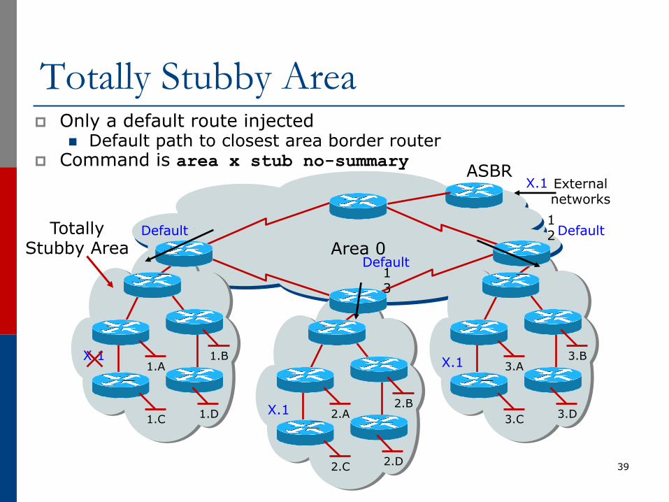
Totally Stubby Areap Only a default route injected
n Default path to closest area border routerp Command is area x stub no-summary
39
3.A3.B
3.C 3.D2.A2.B
2.C 2.D
1.A1.B
1.C 1.D
Area 01 3
1 2
ASBRExternal networks
X.1
X.1
Default
X.1
X.1
Default
DefaultTotally Stubby Area
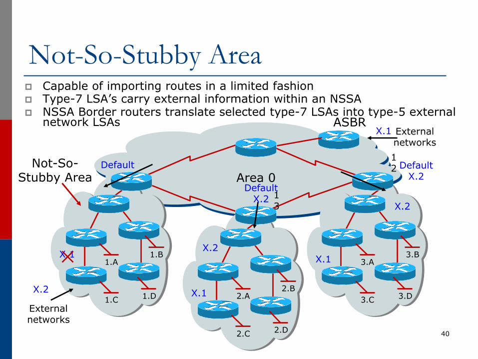
Not-So-Stubby Areap Capable of importing routes in a limited fashionp Type-7 LSA’s carry external information within an NSSAp NSSA Border routers translate selected type-7 LSAs into type-5 external
network LSAs
40
3.A3.B
3.C 3.D2.A2.B
2.C 2.D
1.A1.B
1.C 1.D
Area 01 3
1 2
ASBRExternal networks
X.1
X.1
Default
X.1
X.1
Default X.2
Default X.2
Not-So-Stubby Area
External networks
X.2
X.2
X.2
ISP Use of Areasp ISP networks use:
n Backbone arean Regular area
p Backbone arean No partitioning
p Regular arean Summarisation of point to point link addresses used
within areasn Loopback addresses allowed out of regular areas without
summarisation (otherwise iBGP won’t work)
41
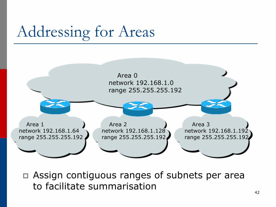
Addressing for Areas
p Assign contiguous ranges of subnets per area to facilitate summarisation
42
Area 1network 192.168.1.64range 255.255.255.192
Area 2network 192.168.1.128range 255.255.255.192
Area 3network 192.168.1.192range 255.255.255.192
Area 0network 192.168.1.0range 255.255.255.192
Summaryp Fundamentals of Scalable OSPF Network
Designn Area hierarchyn DR/BDR selectionn Contiguous intra-area addressingn Route summarisationn Infrastructure prefixes only
43

Introduction to OSPFISP Training Workshops
44