Embed Size (px)
Citation preview
1
EXCAVATION AND TRENCHING
OSHA - SUSAN HARWOOD TRAINING GRANT
• Please sign the attendance sheet
• Take one handout
• Answer the pre-test
WELCOME
2
• Emergency Exits
• Emergency Stairs
• Location of restrooms
• Location of water fountains
LOCATION
3
This material was produced under grant numberSH-16580-SH7 from the Occupational Safety andHealth Administration, U.S. Department of Labor. Itdoes not necessarily reflect the views or policies ofthe U. S. Department of Labor, nor does mention oftrade names, commercial products, ororganizations imply endorsement by the U. S.Government.
Revisions were made to this material under grantnumber SH-05120-SH9 from the OccupationalSafety and Health Administration, U.S. Departmentof Labor.
DISCLAIMER
4
▪ Welcome
▪ Introduction to OSHA
▪ Worker’s rights
▪ Introduction to Trenching and Excavation Hazards
❑What is trenching?
❑Preventing excavation hazard
▪ Common Trenching and Excavation Hazards
▪ Soil Classifications
▪ Exercises
▪ Certificates
AGENDA
5
INTRODUCTIONTO
OSHA
Overview of anti-retaliation provisions, employee rights, employer responsibilities, whistleblower laws, and
OSHA’s complaint investigation procedures
6
2
• OSHA began because, until 1970, there were nonational laws for safety and health hazards.
• On average, 14 workers die every day from jobinjuries
• Worker deaths in America are down–on average,from about 38 worker deaths a day in 1970 to 14 aday in 2017
WORKER FATALITIES
• 5,147 workers died at the job in 2017, 971(20.7%)worked in construction
• Excavation — an average of 19 death per year, from alow of 10 death in 2014 to a high of 33 death in 2016
WHY IS OSHA IMPORTANT TO YOU?
7
(Source: BLS 2018)
DISCUSSION QUESTIONS
• When, during your work experience, did you first hear about OSHA?
• What did you think about OSHA then?
• What do you think OSHA’s job is?
8
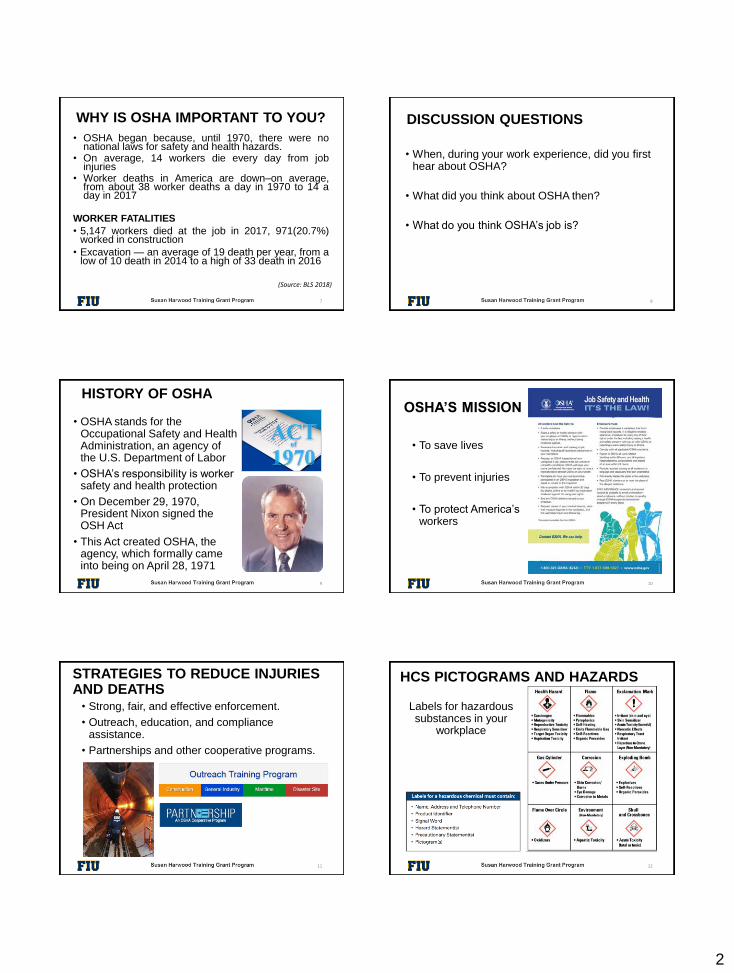
• OSHA stands for the Occupational Safety and Health Administration, an agency of the U.S. Department of Labor
• OSHA’s responsibility is worker safety and health protection
• On December 29, 1970, President Nixon signed the OSH Act
• This Act created OSHA, the agency, which formally came into being on April 28, 1971
HISTORY OF OSHA
9
• To save lives
• To prevent injuries
• To protect America’s workers
OSHA’S MISSION
10
• Strong, fair, and effective enforcement.
• Outreach, education, and compliance assistance.
• Partnerships and other cooperative programs.
STRATEGIES TO REDUCE INJURIES AND DEATHS
11
Labels for hazardous substances in your
workplace
HCS PICTOGRAMS AND HAZARDS
12
3
• The OSH Act authorizes OSHA compliance safety and health officers (CSHOs) to conduct workplace inspections at reasonable times.
• OSHA conducts inspections without advance notice, except in rare circumstances (e.g. Imminent Danger)
• In fact, anyone who tells an employer about an OSHA inspection in advance can receive fines and a jail term.
OSHA INSPECTIONS
13
A typical OSHA on-site inspection includes fourstages:
1. Presentation of inspector credentials.
2. An opening conference.
3. An inspection walk-around.
4. A closing conference.
INSPECTIONS PROCESS
14
Priority Category of Inspection
1st Imminent Danger:Reasonable certainty an immediate danger exists
2nd Fatality/Catastrophe:
Reported to OSHA; inspected ASAP
3rd Complaints/Referrals:Worker or worker representative can file a complaint about a safety or health hazard
4th Programmed Inspections:Cover industries and employers with high injury and illness rates, specific hazards, or other exposures.
OSHA’S INSPECTION PRIORITIES
15
• OSHA evaluates each complaint to determine howit can be handled best--an off-site investigation oran on-site inspection
• Before beginning an inspection, OSHA staff mustbe able to determine from the complaint that thereare reasonable grounds to believe that a violationof an OSHA standard or a safety or health hazardexists.
• If OSHA has information indicating the employer isaware of the hazard and is correcting it, theagency may not conduct an inspection afterobtaining the necessary documentation from theemployer.
OSHA’S COMPLAINT INVESTIGATIONS
16
• Employee may file a complain with OSHAunder Section 11(c) if your employer retaliatesagainst you by taking unfavorable personnelaction because you engaged in protectedactivity relating to workplace safety and health.
• OSHA requires that complaints must be filedwithin 30 days after the alleged retaliation.
CONT.
17
• Your employer may be found to have retaliatedagainst you if your protected activity was acontributing or motivating factor in its decisionto take unfavorable personnel action againstyou. Such actions may include:
RIGHTS AS A WHISTLEBLOWER
Firing or laying off
Blacklisting
Denying overtime or
promotion
Disciplining
Denying benefits
Failing to hire or rehire
Intimidation
Reassignment
affecting promotion
prospects
Reducing pay or hour
18

4
QUESTIONS ABOUT OSHA?
19
DEFINITIONS
20
Excavation
Any man-made cavity or depression in the earth’s surface (including its walls, floor and lip) formed by earth removal. For rescue purposes an excavation is wider than it is deep.
DEFINITIONS
21
Trench
A narrow excavation which is deeper than it is wide, with a maximum width of fifteen (15) feet measured at the floor (bottom).
• Excavation laws, regulations, standards
• Soil classification
• Soil testing
• Competent person responsibilities
• Hazards associated with trenches
• Protective systems
EXCAVATIONS OVERVIEW / MAIN POINTS
22
Excavating is recognized as one of the most hazardous construction operations
• 97 Workers were killed on Excavation/Trenching jobs from 2013-2017.
• From a low of 10 deaths in 2014 to a high of 33 in 2016.
• Cave-ins are more likely than other excavation related accidents to result in worker fatalities.
TRAGIC FACTS
23
(Source: BLS 2018, www.osha.gov)
• 60% of related deaths are rescuers
• Civilians
• Fire dept personnel
• Co-workers
• Cave-ins can happen without warning
• All of the fatalities and injuries could have been prevented
TRAGIC FACTS
24
5
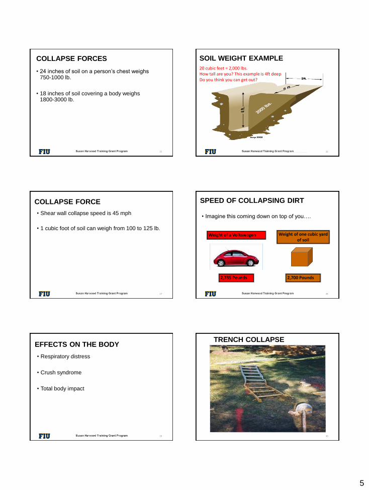
• 24 inches of soil on a person’s chest weighs 750-1000 lb.
• 18 inches of soil covering a body weighs 1800-3000 lb.
COLLAPSE FORCES
25
SOIL WEIGHT EXAMPLE
© ACR Publications Used By Permission 26
20 cubic feet = 2,000 lbs.How tall are you? This example is 4ft deepDo you think you can get out?
• Shear wall collapse speed is 45 mph
• 1 cubic foot of soil can weigh from 100 to 125 lb.
COLLAPSE FORCE
27
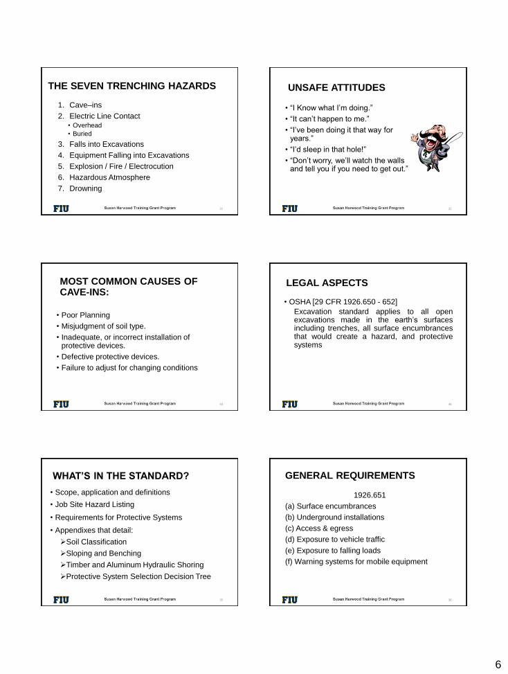
• Imagine this coming down on top of you….
SPEED OF COLLAPSING DIRT
Weight of a Volkswagen
2,785 Pounds
Weight of one cubic yard of soil
2,700 Pounds
28
• Respiratory distress
• Crush syndrome
• Total body impact
EFFECTS ON THE BODY
29
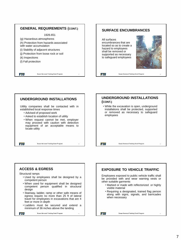
TRENCH COLLAPSE
30
6
THE SEVEN TRENCHING HAZARDS
1. Cave–ins
2. Electric Line Contact• Overhead
• Buried
3. Falls into Excavations
4. Equipment Falling into Excavations
5. Explosion / Fire / Electrocution
6. Hazardous Atmosphere
7. Drowning
31
UNSAFE ATTITUDES
• “I Know what I’m doing.”
• “It can’t happen to me.”
• “I’ve been doing it that way for years.”
• “I’d sleep in that hole!”
• “Don’t worry, we’ll watch the walls and tell you if you need to get out.”
32
• Poor Planning
• Misjudgment of soil type.
• Inadequate, or incorrect installation of protective devices.
• Defective protective devices.
• Failure to adjust for changing conditions
MOST COMMON CAUSES OF CAVE-INS:
33
LEGAL ASPECTS
• OSHA [29 CFR 1926.650 - 652]
Excavation standard applies to all openexcavations made in the earth’s surfacesincluding trenches, all surface encumbrancesthat would create a hazard, and protectivesystems
34
WHAT’S IN THE STANDARD?
• Scope, application and definitions
• Job Site Hazard Listing
• Requirements for Protective Systems
• Appendixes that detail:
➢Soil Classification
➢Sloping and Benching
➢Timber and Aluminum Hydraulic Shoring
➢Protective System Selection Decision Tree
35
GENERAL REQUIREMENTS
1926.651
(a) Surface encumbrances
(b) Underground installations
(c) Access & egress
(d) Exposure to vehicle traffic
(e) Exposure to falling loads
(f) Warning systems for mobile equipment
36
7
1926.651
(g) Hazardous atmospheres
(h) Protection from hazards associated with water accumulation
(i) Stability of adjacent structures
(j) Protection from loose rock or soil
(k) Inspections
(l) Fall protection
37
GENERAL REQUIREMENTS (CONT.)SURFACE ENCUMBRANCES
All surfaces encumbrances that are located so as to create a hazard to employees shall be removed or supported as necessary to safeguard employees
38
UNDERGROUND INSTALLATIONS
Utility companies shall be contacted with inestablished local response times
• Advised of proposed work
• Asked to establish location of utility
• When request cannot be met, employermay proceed with caution with detectionequipment of an acceptable means tolocate utility
39
UNDERGROUND INSTALLATIONS (CONT.)
• While the excavation is open, undergroundinstallations shall be protected, supportedor removed as necessary to safeguardemployees
40
ACCESS & EGRESS
Structural ramps
• Used by employees shall be designed by acompetent person
• When used for equipment shall be designedcompetent person qualified in structuraldesign
• Stairway, ladder, ramp or other safe means ofegress require no more than 25 ft of lateraltravel for employees in excavations that are 4feet or more in depth
• Ladders must be secured and extend aminimum of 36 inches above the landing
41
EXPOSURE TO VEHICLE TRAFFIC
Employees exposed to public vehicle traffic shallbe provided with and wear warning vests orother suitable garments
• Marked or made with reflectorized or highlyvisible material
• Requiring a designated, trained flag personalong with signs, signals, and barricadeswhen necessary
42
8
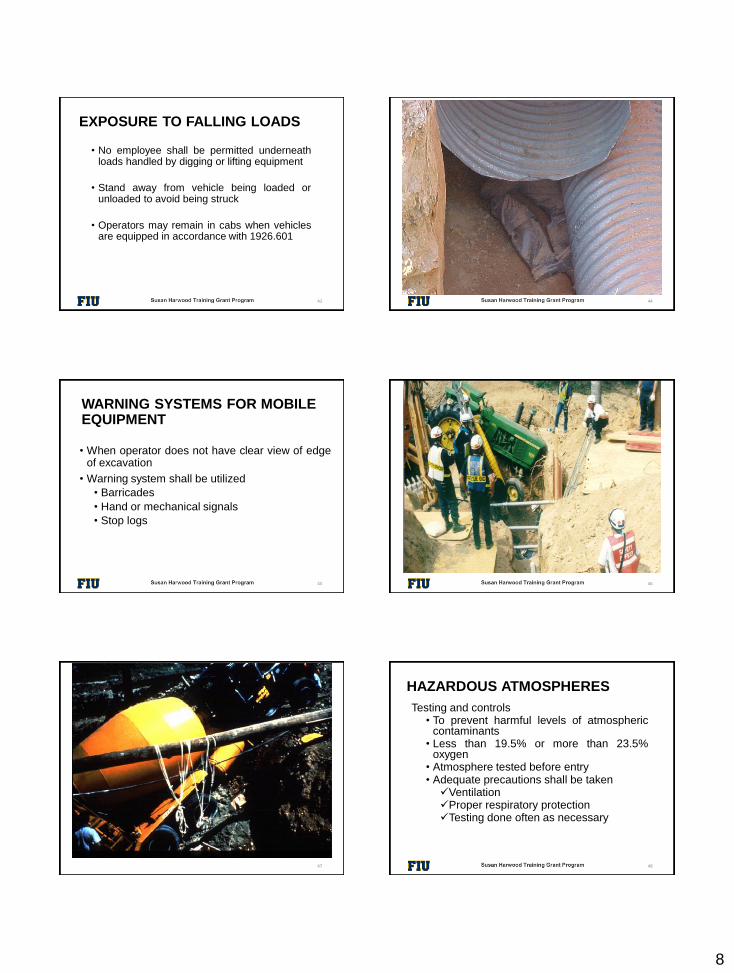
EXPOSURE TO FALLING LOADS
• No employee shall be permitted underneathloads handled by digging or lifting equipment
• Stand away from vehicle being loaded orunloaded to avoid being struck
• Operators may remain in cabs when vehiclesare equipped in accordance with 1926.601
43
STUCK-IN
44
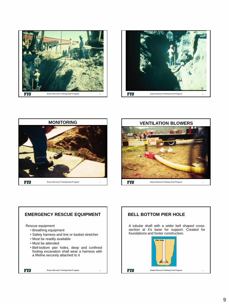
WARNING SYSTEMS FOR MOBILE EQUIPMENT
• When operator does not have clear view of edgeof excavation
• Warning system shall be utilized
• Barricades
• Hand or mechanical signals
• Stop logs
45
EXCAVATION WITHOUT PROPER BARRICADE
46
VEHICLE FALLING IN EXCAVATION
47
HAZARDOUS ATMOSPHERES
Testing and controls• To prevent harmful levels of atmospheric
contaminants• Less than 19.5% or more than 23.5%
oxygen• Atmosphere tested before entry• Adequate precautions shall be taken✓Ventilation✓Proper respiratory protection✓Testing done often as necessary
48
9
EXPOSED TO HAZARDOUS ATMOSPHERE
49
ATMOSPHERE
50
MONITORING
51
VENTILATION BLOWERS
52
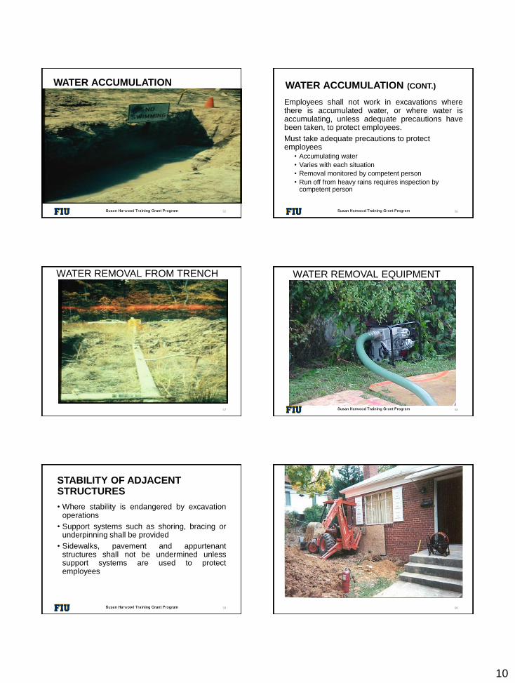
EMERGENCY RESCUE EQUIPMENT
Rescue equipment
• Breathing equipment
• Safety harness and line or basket stretcher
• Must be readily available
• Must be attended
• Bell-bottom pier holes, deep and confinedfooting excavation shall wear a harness witha lifeline securely attached to it
53 54
BELL BOTTOM PIER HOLE
A tubular shaft with a wider bell shaped cross-section at it’s base for support. Created forfoundations and footer construction.
10
WATER ACCUMULATION
55
WATER ACCUMULATION (CONT.)
Employees shall not work in excavations wherethere is accumulated water, or where water isaccumulating, unless adequate precautions havebeen taken, to protect employees.
Must take adequate precautions to protect employees
• Accumulating water
• Varies with each situation
• Removal monitored by competent person
• Run off from heavy rains requires inspection by competent person
56
WATER REMOVAL FROM TRENCH
57
WATER REMOVAL EQUIPMENT
58
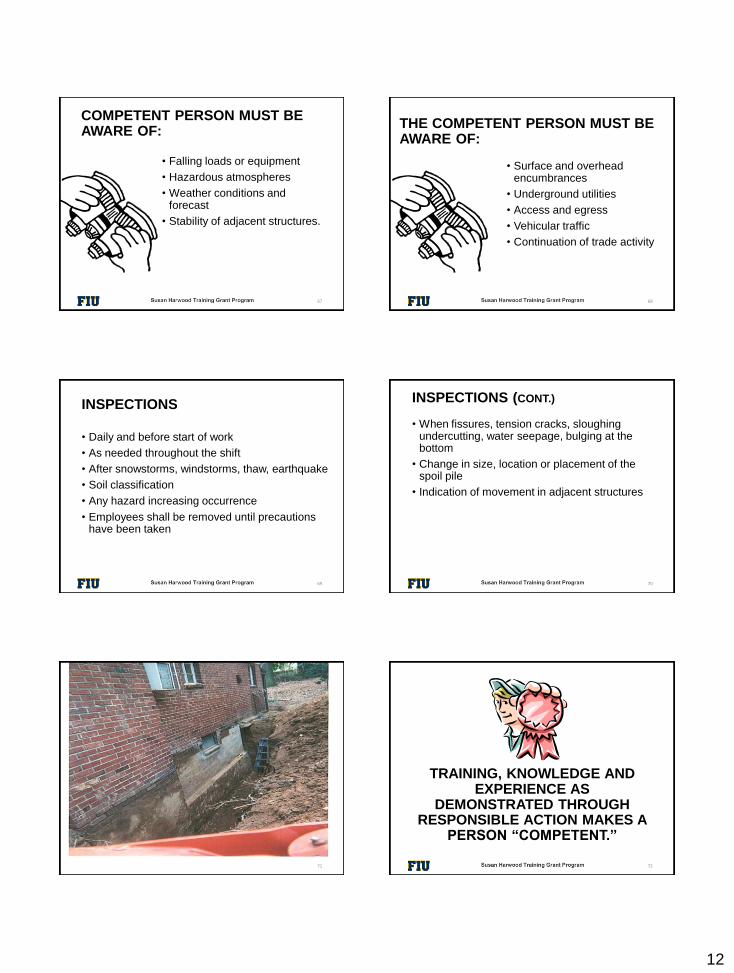
STABILITY OF ADJACENT STRUCTURES
• Where stability is endangered by excavationoperations
• Support systems such as shoring, bracing orunderpinning shall be provided
• Sidewalks, pavement and appurtenantstructures shall not be undermined unlesssupport systems are used to protectemployees
59
STRUCTURAL FAILURE
60

11
LEVEL
61
PROTECTION FROM LOOSE ROCK AND SOIL
Hazard from falling or rolling from excavation face
• Scaling to remove loose materials
• Installation of protective barricades
• Other means (retaining devices)
• 2 feet from edge of excavation
62
TRENCH
63
WHAT’S GOOD?
64
WHAT’S NOT SO GOOD?
WHO IS COMPETENT PERSON
• One who is capable of identifying existing orpredictable hazards in the surroundings whichare unsanitary, hazardous or dangerous toemployees & who has authorization to takeprompt corrective measures
65
COMPETENT PERSON
• Has specific training in and be knowledgeableabout soil analysis, use of protective systemsand the requirements of the standard
66
12
COMPETENT PERSON MUST BE AWARE OF:
• Falling loads or equipment
• Hazardous atmospheres
• Weather conditions and forecast
• Stability of adjacent structures.
67
THE COMPETENT PERSON MUST BE AWARE OF:
• Surface and overhead encumbrances
• Underground utilities
• Access and egress
• Vehicular traffic
• Continuation of trade activity
68
INSPECTIONS
• Daily and before start of work
• As needed throughout the shift
• After snowstorms, windstorms, thaw, earthquake
• Soil classification
• Any hazard increasing occurrence
• Employees shall be removed until precautions have been taken
69
INSPECTIONS (CONT.)
• When fissures, tension cracks, sloughing undercutting, water seepage, bulging at the bottom
• Change in size, location or placement of the spoil pile
• Indication of movement in adjacent structures
70
HAZARD
71
TRAINING, KNOWLEDGE AND EXPERIENCE AS
DEMONSTRATED THROUGH RESPONSIBLE ACTION MAKES A
PERSON “COMPETENT.”
72
13
FALL PROTECTION
If walkway provided
• Where employees permitted to cross, guardrails provided where 6 feet or more abovelower levels
• Fall protection standard
73
REQUIREMENTS OFPROTECTIVE SYSTEMS
1926.652
• Employees shall be protected from cave-in by an adequate protective system except;
• Entirely in stable rock
• Less than 5 feet in depth with no indication of cave-in
74
NO PROPER PROTECTION
75
PROPER SHORING
76
DESIGNS USING MANUFACTURERS DATA
• Deviation will only be allowed after manufacturer issues specific written approval
• Written form at the job site during construction
77
MATERIALS AND EQUIPMENT
• Free of damage and defects
• Maintain in manner consistent with manufactures data
• Examined by competent person & evaluated for continued use
• Removed from service until approved by registered professional engineer
78
14
TRENCH BOX
79
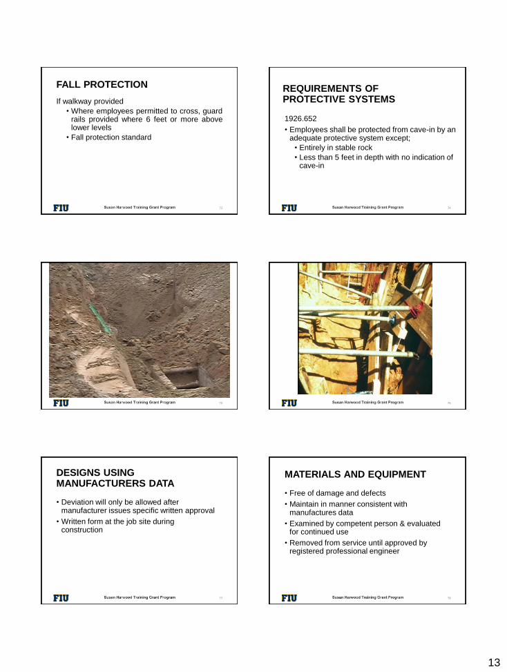
TRENCH BOXES
80
INSTALLATION & REMOVAL
• Members securely connected
• Prevent sliding, falling, kick outs
• Other predictable failure
• Members shall not subjected to loads exceeding those which were designed
• Members removed from bottom first
• Back fill with removal of support system
81
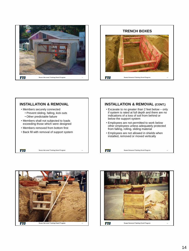
INSTALLATION & REMOVAL (CONT.)
• Excavate to no greater than 2 feet below – only if system is rated at full depth and there are no indications of a loss of soil from behind or below the support system
• Employees are not permitted to work below other employees unless adequately protected from falling, rolling, sliding material
• Employees are not allowed in shields when installed, removed or moved vertically
82
REMOVAL OF TRENCH BOX
83
PICTURE OF TRENCH
84
15
PROPER TRENCH BOX
85
SHIELD TESTING
86
SHIELD TESTING BY COMPETENT PERSON
87
GUESS
88
WHAT’S NOT SO GOOD?
WHAT’S GOOD?
SHIELD USED WITH SLOPING
89
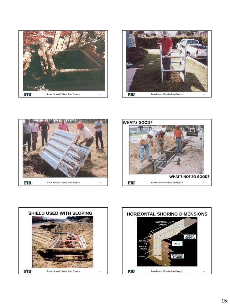
HORIZONTAL SHORING DIMENSIONS
© ACR Publications Used By Permission90
HORIZONTAL SPACING
18” MAX
4’ MAX
VERTICAL SPACING
16
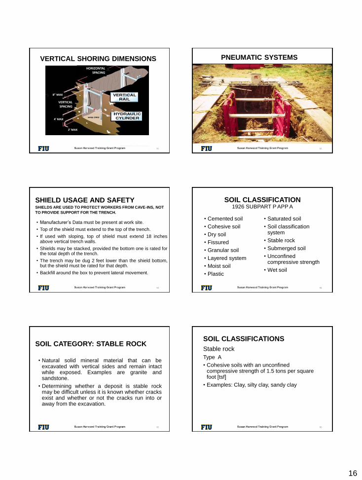
VERTICAL SHORING DIMENSIONS
© ACR Publications Used By Permission
91
HORIZONTAL SPACING
8” MAX
4’ MAX
2’ MAX
VERTICAL SPACING
PNEUMATIC SYSTEMS
92
SHIELD USAGE AND SAFETYSHIELDS ARE USED TO PROTECT WORKERS FROM CAVE-INS, NOT
TO PROVIDE SUPPORT FOR THE TRENCH.
• Manufacturer’s Data must be present at work site.
• Top of the shield must extend to the top of the trench.
• If used with sloping, top of shield must extend 18 inchesabove vertical trench walls.
• Shields may be stacked, provided the bottom one is rated forthe total depth of the trench.
• The trench may be dug 2 feet lower than the shield bottom,but the shield must be rated for that depth.
• Backfill around the box to prevent lateral movement.
93
SOIL CLASSIFICATION1926 SUBPART P APP A
• Cemented soil
• Cohesive soil
• Dry soil
• Fissured
• Granular soil
• Layered system
• Moist soil
• Plastic
• Saturated soil
• Soil classification system
• Stable rock
• Submerged soil
• Unconfined compressive strength
• Wet soil
94
SOIL CATEGORY: STABLE ROCK
• Natural solid mineral material that can beexcavated with vertical sides and remain intactwhile exposed. Examples are granite andsandstone.
• Determining whether a deposit is stable rockmay be difficult unless it is known whether cracksexist and whether or not the cracks run into oraway from the excavation.
95
SOIL CLASSIFICATIONS
Stable rock
Type A
• Cohesive soils with an unconfined compressive strength of 1.5 tons per square foot [tsf]
• Examples: Clay, silty clay, sandy clay
96
17
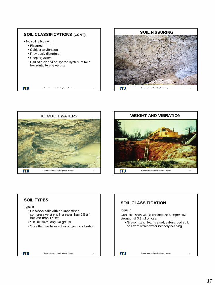
SOIL CLASSIFICATIONS (CONT.)
• No soil is type A if;
• Fissured
• Subject to vibration
• Previously disturbed
• Seeping water
• Part of a sloped or layered system of four horizontal to one vertical
97
SOIL FISSURING
98
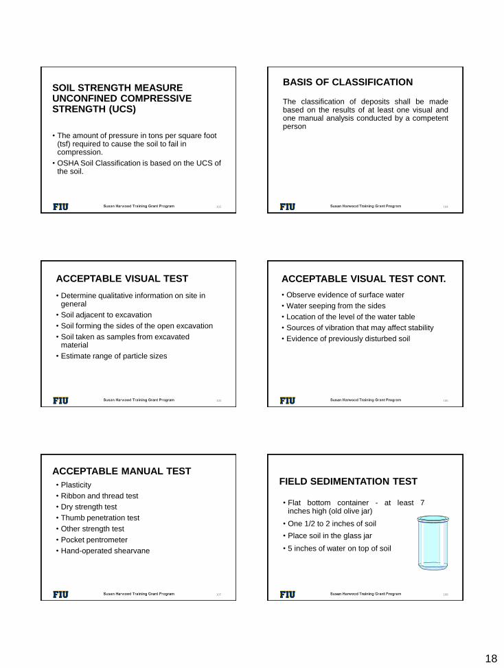
TO MUCH WATER?
99
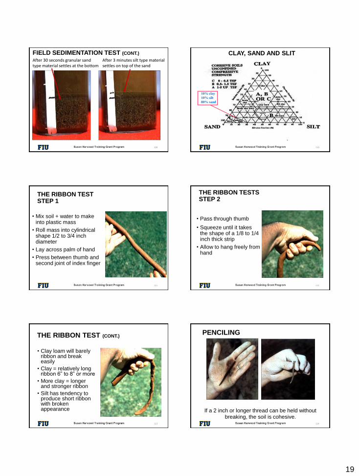
WEIGHT AND VIBRATION
100
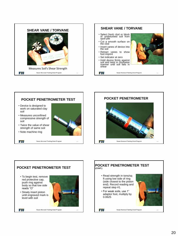
SOIL TYPES
Type B
• Cohesive soils with an unconfined compressive strength greater than 0.5 tsfbut less than 1.5 tsf
• Silt, silt loam, angular gravel
• Soils that are fissured, or subject to vibration
101
SOIL CLASSIFICATION
Type C
Cohesive soils with a unconfined compressive strength of 0.5 tsf or less.
• Gravel, sand, loamy sand, submerged soil, soil from which water is freely seeping
102
18
SOIL STRENGTH MEASUREUNCONFINED COMPRESSIVE STRENGTH (UCS)
• The amount of pressure in tons per square foot (tsf) required to cause the soil to fail in compression.
• OSHA Soil Classification is based on the UCS of the soil.
103
BASIS OF CLASSIFICATION
The classification of deposits shall be madebased on the results of at least one visual andone manual analysis conducted by a competentperson
104
ACCEPTABLE VISUAL TEST
• Determine qualitative information on site in general
• Soil adjacent to excavation
• Soil forming the sides of the open excavation
• Soil taken as samples from excavated material
• Estimate range of particle sizes
105
ACCEPTABLE VISUAL TEST CONT.
• Observe evidence of surface water
• Water seeping from the sides
• Location of the level of the water table
• Sources of vibration that may affect stability
• Evidence of previously disturbed soil
106
ACCEPTABLE MANUAL TEST
• Plasticity
• Ribbon and thread test
• Dry strength test
• Thumb penetration test
• Other strength test
• Pocket pentrometer
• Hand-operated shearvane
107
FIELD SEDIMENTATION TEST
• Flat bottom container - at least 7inches high (old olive jar)
• One 1/2 to 2 inches of soil
• Place soil in the glass jar
• 5 inches of water on top of soil
108
19
After 30 seconds granular sand type material settles at the bottom
After 3 minutes silt type material settles on top of the sand
FIELD SEDIMENTATION TEST (CONT.)
109
10% clay
10% silt
80% sand
CLAY, SAND AND SLIT
110
THE RIBBON TESTSTEP 1
• Mix soil + water to make into plastic mass
• Roll mass into cylindrical shape 1/2 to 3/4 inch diameter
• Lay across palm of hand
• Press between thumb and second joint of index finger
111
• Pass through thumb
• Squeeze until it takes the shape of a 1/8 to 1/4 inch thick strip
• Allow to hang freely from hand
THE RIBBON TESTS STEP 2
112
THE RIBBON TEST (CONT.)
113
• Clay loam will barely ribbon and break easily
• Clay = relatively long ribbon 6” to 8” or more
• More clay = longer and stronger ribbon
• Silt has tendency to produce short ribbon with broken appearance If a 2 inch or longer thread can be held without
breaking, the soil is cohesive.
PENCILING
114
20
SHEAR VANE / TORVANE
Measures Soil’s Shear Strength
115
SHEAR VANE / TORVANE
116
• Select fresh clod or blockof undisturbed soil fromspoil pile
• Cut a smooth surface onthe clod
• Insert vanes of device intothe soil
• Retract vanes to showfoot imprint
• Set indicator at zero
• Hold device firmly againstsoil and twist in clockwisemanner until soil fails inshear
POCKET PENETROMETER TEST
117
• Device is designed to work on saturated clay soil
• Measures unconfined compressive strength of soil
• Twice the value of shear strength of same soil
• Note machine ring
POCKET PENETROMETER
118
POCKET PENETROMETER TEST
• To begin test, remove red protective cap, push ring against body so that low side reads “O”
• Slowly insert piston until engraved mark is level with soil
119
POCKET PENETROMETER TEST(CONT.)
120
• Read strength in tons/sqft using low side of ring (side closest to the piston end). Record reading and repeat step #1.
• For weak soils, use 1” adaptor foot, multiply by 0.0625
21
THUMB PENETRATION TEST
• The thumb penetration procedure involves an attempt to press the thumb firmly into the soil in question.
121
• If the thumb makes an indentation in the soil only with great difficulty, the soil is probably Type A.
• If the thumb penetrates no further then the length of the thumb nail, it is probably Type B soil.
• If the thumb penetrates the full length of the thumb it is Type C soil.
• The thumb test is subjective and is therefore the least accurate of the tests.
122
THUMB PENETRATION TEST (CONT.)
SOIL CLASSIFICATIONS.
• Layered Geological Strata
• where soils are configured in layers
• must be classified on the basis of the weakest soil
• each layer may be classified individually if a more stable layer lies below a less stable layer
• Type C soil rests on top of stable rock
123
• Look for the following conditions• Particle size✓Primarily fine grained=cohesive material✓Primarily coarse-grained sand or gravel✓Granular material
• Cohesion✓Remains in clumps=cohesive
124
CLASSIFICATION
SOIL STRENGTH IS DEPENDENT UPON:
• Type of Soil.
• Amount of Moisture in the Soil.
• Whether the Soil Has Been Previously Disturbed.
125
• It Brings Additional Weight
• Hydrostatic Pressure
• It Erodes the Trench Wall
• Water movement typically moves soil
• It Can Freeze and Thaw
• Resulting in cracks & false cohesion
REMOVAL OF GROUND WATER IS CRITICAL
IF WATER IS ADDED
126
22
SOIL COMPONENTS
• Clay:
Composed of mineral particles less than 0.002 mm in diameter
• Silt:
Individual mineral fragments that range from 0.002 to 0.05 mm in diameter.
• Sand:
Individual rock or mineral fragments that range in diameter from 0.05 to 2.0 mm in diameter.
• Gravel:
Can be either angular or rounded.
127
COHESIVE SOIL
• Soil with a high clay content which has cohesive strength.
• It does not crumble.
• It can be excavated with vertical side slopes.
• It is hard to break up when dry.
• It can be molded.
• It exhibits significant cohesion even when submerged.
128
GRANULAR SOIL
• Soils that include gravel, sand, silt.
• Very low clay content.
• It has no cohesive strength.
• Some moist granular soils exhibit apparent cohesion.
• It cannot be molded when moist and crumbles easily when dry.
129
SOIL MECHANICS
• Toppling occurs when the trench’s vertical face shears along the tension crack line and topples into the excavation
130
TOPPLING
131
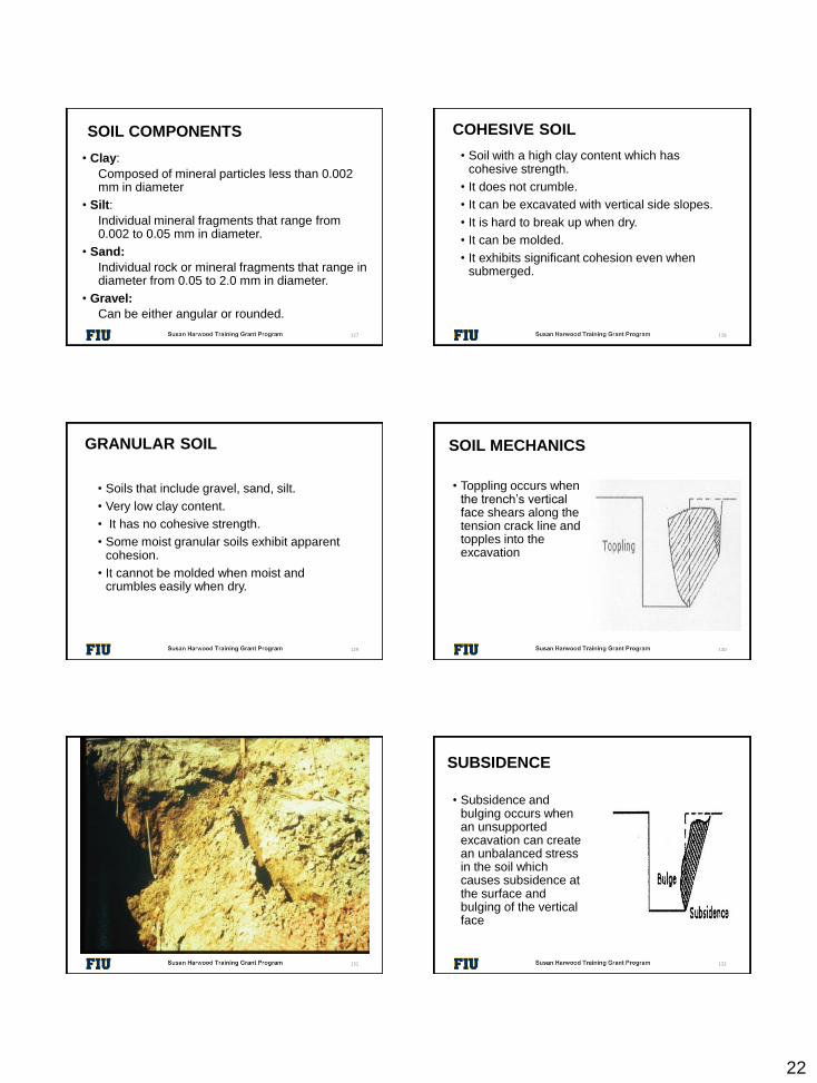
SUBSIDENCE
• Subsidence and bulging occurs when an unsupported excavation can create an unbalanced stress in the soil which causes subsidence at the surface and bulging of the vertical face
132

23
UNSUPPORTED EXCAVATION
133
BULGING
134
SOIL MECHANIC
• Heaving or squeezing is caused by the downward pressure created by the weight of adjoining soil or equipment
• Can occur even when shoring or shielding has been properly installed
135
FORCES ACTING ON A TRENCH
© ACR Publications Used By Permission
136
BOILING
• Boiling is evidenced by an upward water flow into the bottom of the cut
• High water table is one cause
• Boiling produces a quick condition even when trench boxes are used
137
TRENCH BOILING
138
24
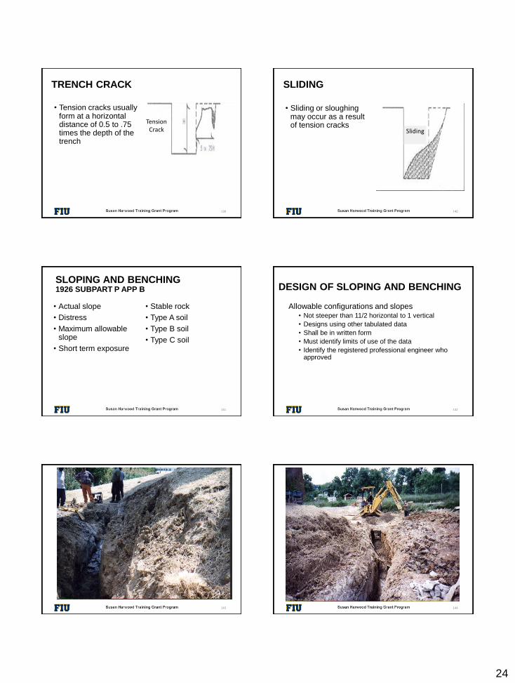
TRENCH CRACK
• Tension cracks usually form at a horizontal distance of 0.5 to .75 times the depth of the trench
139
Tension Crack
• Sliding or sloughing may occur as a result of tension cracks
140
SLIDING
Sliding
SLOPING AND BENCHING1926 SUBPART P APP B
• Actual slope
• Distress
• Maximum allowable slope
• Short term exposure
• Stable rock
• Type A soil
• Type B soil
• Type C soil
141
DESIGN OF SLOPING AND BENCHING
Allowable configurations and slopes• Not steeper than 11/2 horizontal to 1 vertical
• Designs using other tabulated data
• Shall be in written form
• Must identify limits of use of the data
• Identify the registered professional engineer who approved
142
IMPROPER DESIGN
143
IMPROPER SLOPING
144
25
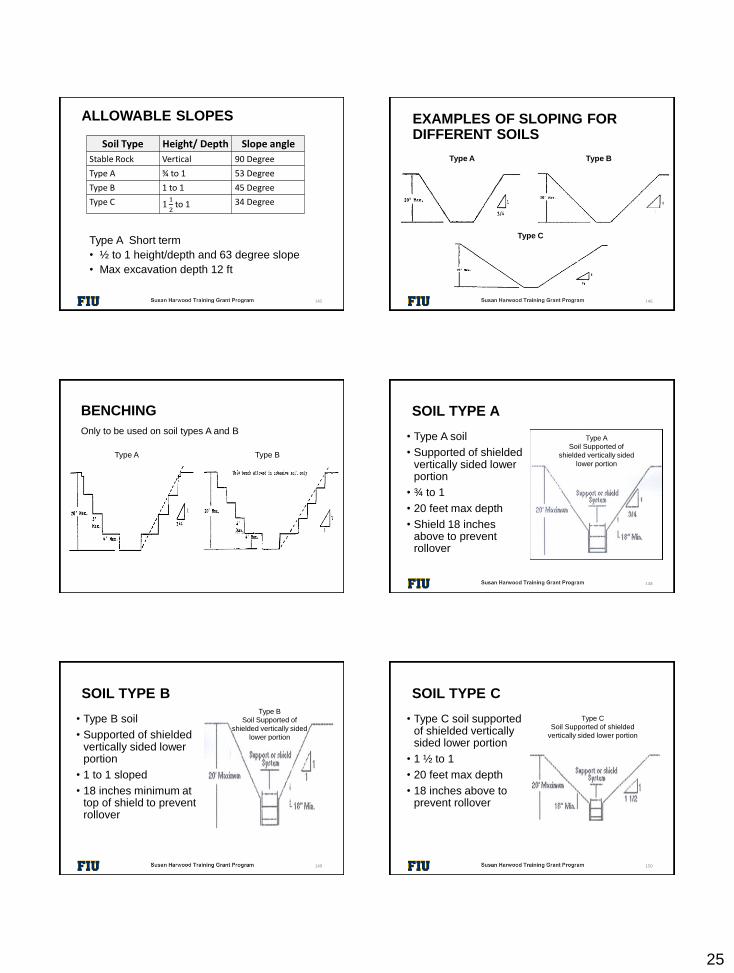
ALLOWABLE SLOPES
Type A Short term
• ½ to 1 height/depth and 63 degree slope
• Max excavation depth 12 ft
145
Soil Type Height/ Depth Slope angle
Stable Rock Vertical 90 Degree
Type A ¾ to 1 53 Degree
Type B 1 to 1 45 Degree
Type C 11
2to 1 34 Degree
EXAMPLES OF SLOPING FOR DIFFERENT SOILS
Type A Type B
Type C
146
BENCHING
Only to be used on soil types A and B
Type A Type B
SOIL TYPE A
• Type A soil
• Supported of shielded vertically sided lower portion
• ¾ to 1
• 20 feet max depth
• Shield 18 inches above to prevent rollover
148
Type A
Soil Supported of
shielded vertically sided
lower portion
SOIL TYPE B
• Type B soil
• Supported of shielded vertically sided lower portion
• 1 to 1 sloped
• 18 inches minimum at top of shield to prevent rollover
149
Type B
Soil Supported of
shielded vertically sided
lower portion
SOIL TYPE C
• Type C soil supported of shielded vertically sided lower portion
• 1 ½ to 1
• 20 feet max depth
• 18 inches above to prevent rollover
150
Type C
Soil Supported of shielded
vertically sided lower portion
26
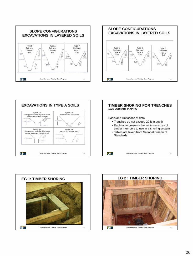
SLOPE CONFIGURATIONSEXCAVATIONS IN LAYERED SOILS
151
Type B
Soil over
Type A
Soil
Type A
Soil over
Type B
Soil
Type A
Soil over
Type C
Soil
SLOPE CONFIGURATIONSEXCAVATIONS IN LAYERED SOILS
152
Type C
Soil over
Type A
Soil
Type C
Soil over
Type B
Soil
Type B
Soil over
Type C
Soil
EXCAVATIONS IN TYPE A SOILS
153
Type A Soil
Unsupported vertically sided lower
portion Max 12 feet in depth
Type A Soil
Simple Bench Excavation
Type A Soil
Simple Slope Short Term
Type A Soil
Unsupported vertically sided lower
portion Maximum 8 feet in depth
TIMBER SHORING FOR TRENCHES1926 SUBPART P APP C
Basis and limitations of data
• Trenches do not exceed 20 ft in depth
• Each table presents the minimum sizes of timber members to use in a shoring system
• Tables are taken from National Bureau of Standards
154
EG 1: TIMBER SHORING
155
EG 2 : TIMBER SHORING
156
27
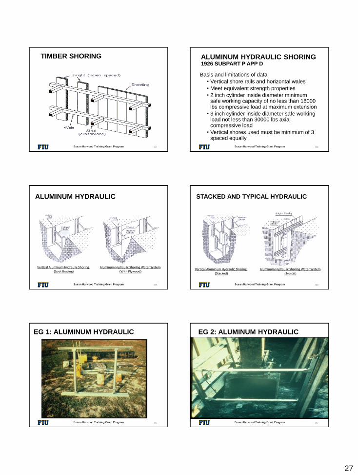
TIMBER SHORING
157
ALUMINUM HYDRAULIC SHORING 1926 SUBPART P APP D
Basis and limitations of data
• Vertical shore rails and horizontal wales
• Meet equivalent strength properties
• 2 inch cylinder inside diameter minimum safe working capacity of no less than 18000 lbs compressive load at maximum extension
• 3 inch cylinder inside diameter safe working load not less than 30000 lbs axial compressive load
• Vertical shores used must be minimum of 3 spaced equally
158
ALUMINUM HYDRAULIC
159
Vertical Aluminum Hydraulic Shoring (Spot Bracing)
Aluminum Hydraulic Shoring Water System(With Plywood)
160
STACKED AND TYPICAL HYDRAULIC
Vertical Aluminum Hydraulic Shoring (Stacked)
Aluminum Hydraulic Shoring Water System(Typical)
161
EG 1: ALUMINUM HYDRAULIC EG 2: ALUMINUM HYDRAULIC
162
28
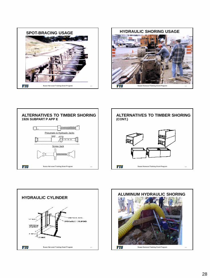
SPOT-BRACING USAGE
163
HYDRAULIC SHORING USAGE
164
ALTERNATIVES TO TIMBER SHORING1926 SUBPART P APP E
165
Pneumatic & Hydraulic Jacks
Screw Jack
166
ALTERNATIVES TO TIMBER SHORING(CONT.)
167
HYDRAULIC CYLINDERALUMINUM HYDRAULIC SHORING
168
29
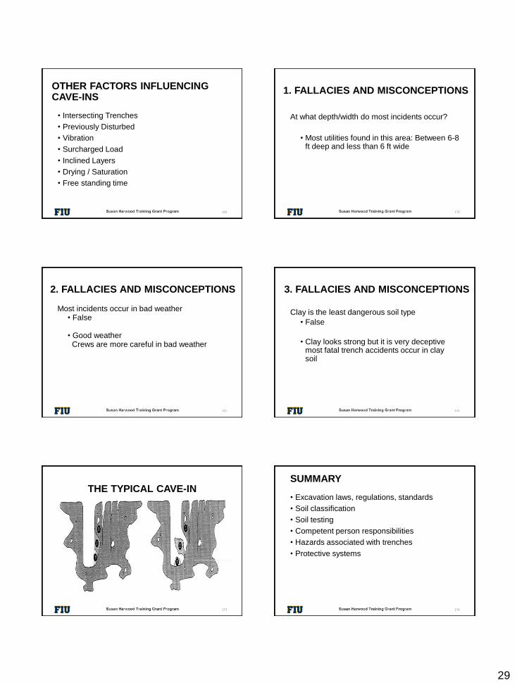
OTHER FACTORS INFLUENCING CAVE-INS
169
• Intersecting Trenches
• Previously Disturbed
• Vibration
• Surcharged Load
• Inclined Layers
• Drying / Saturation
• Free standing time
1. FALLACIES AND MISCONCEPTIONS
At what depth/width do most incidents occur?
• Most utilities found in this area: Between 6-8 ft deep and less than 6 ft wide
170
Most incidents occur in bad weather• False
• Good weather Crews are more careful in bad weather
171
2. FALLACIES AND MISCONCEPTIONS
Clay is the least dangerous soil type
• False
• Clay looks strong but it is very deceptive most fatal trench accidents occur in clay soil
172
3. FALLACIES AND MISCONCEPTIONS
THE TYPICAL CAVE-IN
© ACR Publications Used By Permission
173
SUMMARY
• Excavation laws, regulations, standards
• Soil classification
• Soil testing
• Competent person responsibilities
• Hazards associated with trenches
• Protective systems
174