Embed Size (px)
Citation preview
Introduction to Offshore Engineering
Yutaek Seo
Inlet receiving
• Gas and liquids that enter the gas processing facilities pass
emergency shutdown valves, and then go to inlet receiving,
where condensed phases drop out. Gas from inlet receiving
goes to inlet compression if necessary, and the liquids go to
storage for further processing.
• Separator principles
: Effective phase separators protect downstream equipment
designed to process a single phase. It is the critical first step in
most processes in gas plants and typically is a simple vessel with
internal components to enhance separation.
Gas-Liquid separation
• Separator vessel orientation can be vertical or horizontal.
• Vertical separators are most commonly used when the liquid-to-
gas ratio is low or gas flow rates are low. They are preferred
offshore because they occupy less platform area.
• However, gas flow is upwards and opposes the flow of liquid
droplets. Therefore, vertical separators can be bigger and, thus,
more costly than horizontal separators. Inlet suction scrubbers
at compressor stations are usually vertical.
• Horizontal separators are favored for large liquid volumes or if
the liquid-to-gas ratio is high. Lower gas flow rates and
increased residence times offer better liquid dropout.
• The larger surface area provides better degassing and more
stable liquid levels as well.
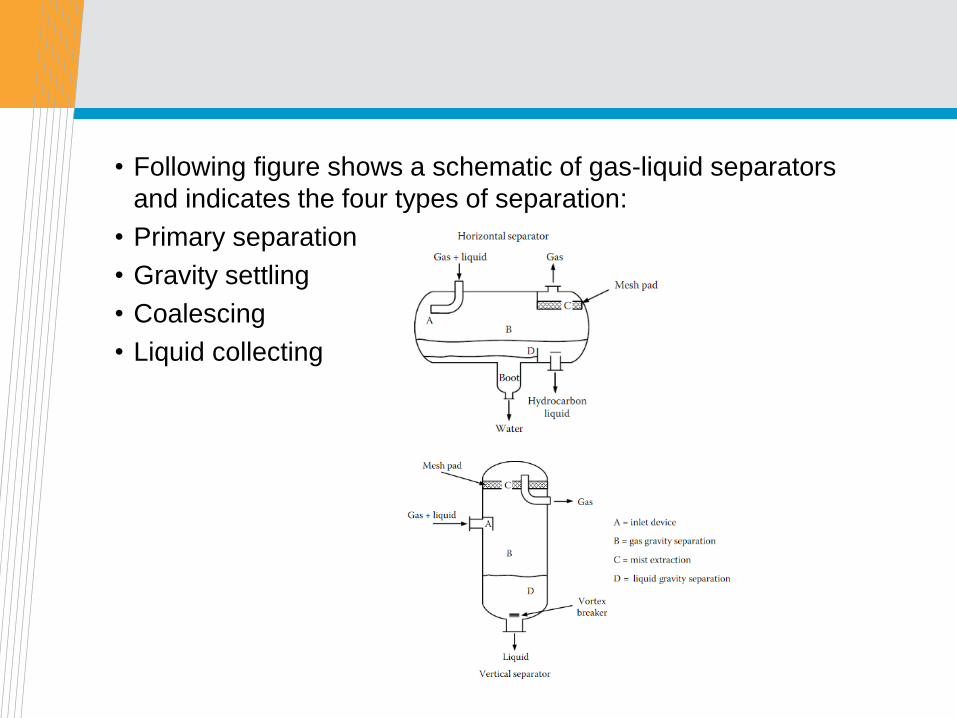
• Following figure shows a schematic of gas-liquid separators
and indicates the four types of separation:
• Primary separation
• Gravity settling
• Coalescing
• Liquid collecting
Primary separation
• Primary separation is accomplished by utilizing the difference in
momentum between gas and liquid.
• Larger liquid droplets fail to make the sharp turn and impinge on
the inlet wall.
• This action coalesces finer droplets so that they drop out
quickly.
• Although inlet geometries vary, most separators use this
approach to knock out a major portion of the incoming liquid.
Gravity settling
• Gravity settling requires low gas velocities with minimal
turbulence to permit droplet fallout.
• The terminal-settling velocity, VT, for a sphere falling through a
stagnant fluid is governed by particle diameter, density
differences, gas viscosity, and a drag coefficient that is a
function of both droplet shape and Reynolds number.
• the Reynolds number is defined as
where D p is particle diameter, ρg is the density, and μ g is the
viscosity.
• Thus, calculations for VT are an iterative process.
• For large particles (1,000 to ~70,000 micron), the terminal
velocity is computed by the equation
where g is the gravitational constant.
• This equation, known as Newton’s law, applies when the
Reynolds number is greater than 500.
• If the particle size is too large, excessive turbulence occurs and
Eq (3.5) fails. The upper limit is found by use of the equation
With KCR = 18.13 and 23.64 for engineering and metric units,
respectively, and is based upon a Reynolds number of 200,000,
which is the upper limit for Newton’s law to hold.
• At the other extreme, where the flow is laminar (NRe < 2),
Stokes’ law applies. The terminal velocity is
where Eq (3.7a) is in English units and Eq (3.7b) is in SI.
• Stokes’ law applies to particles in the 3 to 100 micron range.
• To find the maximum size particle in this flow regime, use KCR =
0.0080 in Eq (3.6), which corresponds to an NRe of 2.
• Particles smaller than 3 microns will not settle because of
Brownian motion.
• Unfortunately, droplets that condense from a vapor tend to be in
the 0.1 to 10 micronrange; the majority are around 1 micron.
• Entrained droplets are 100 times larger. To reduce turbulence,
the settling section may contain vanes. They also act as droplet
collectors to reduce the distance droplets must fall.
Coalescing
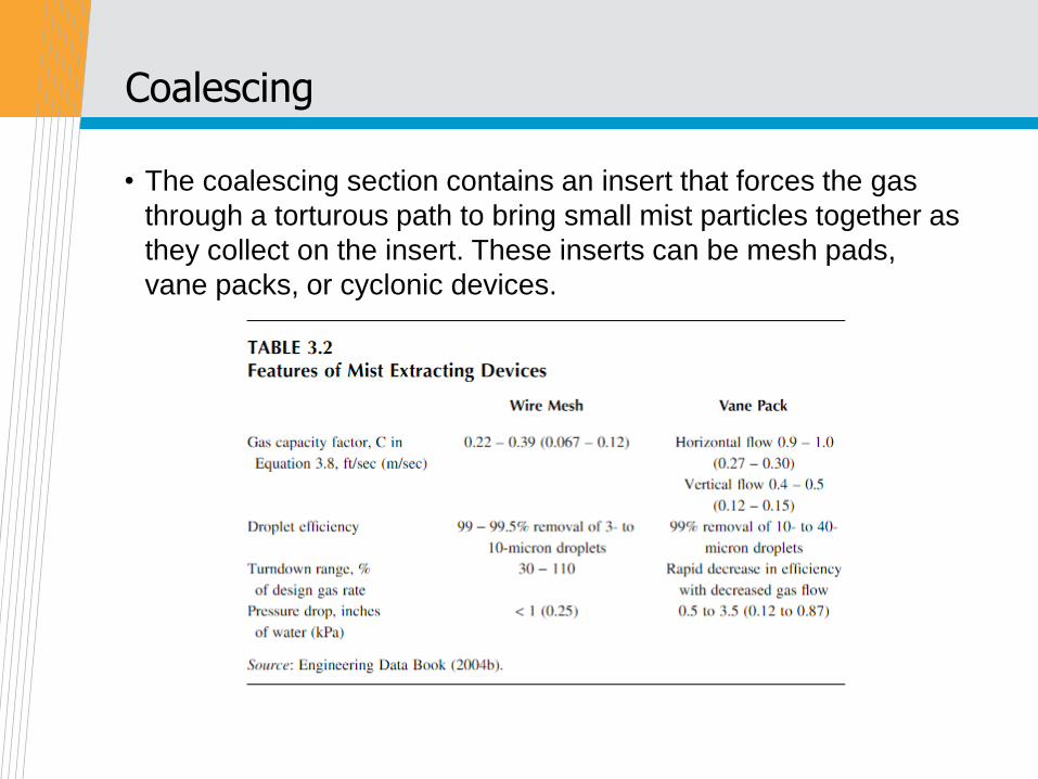
• The coalescing section contains an insert that forces the gas
through a torturous path to bring small mist particles together as
they collect on the insert. These inserts can be mesh pads,
vane packs, or cyclonic devices.
• Mesh pads are either wire or knitted mesh, usually about 6
inches (15 cm) thick, and, preferably, are mounted horizontally
with upward gas flow, but they can be vertical.
• They loose effectiveness if tilted. Mesh pads tend to be more
effective at mist removal than vane packs but are subject to
plugging by solids and heavy oils.
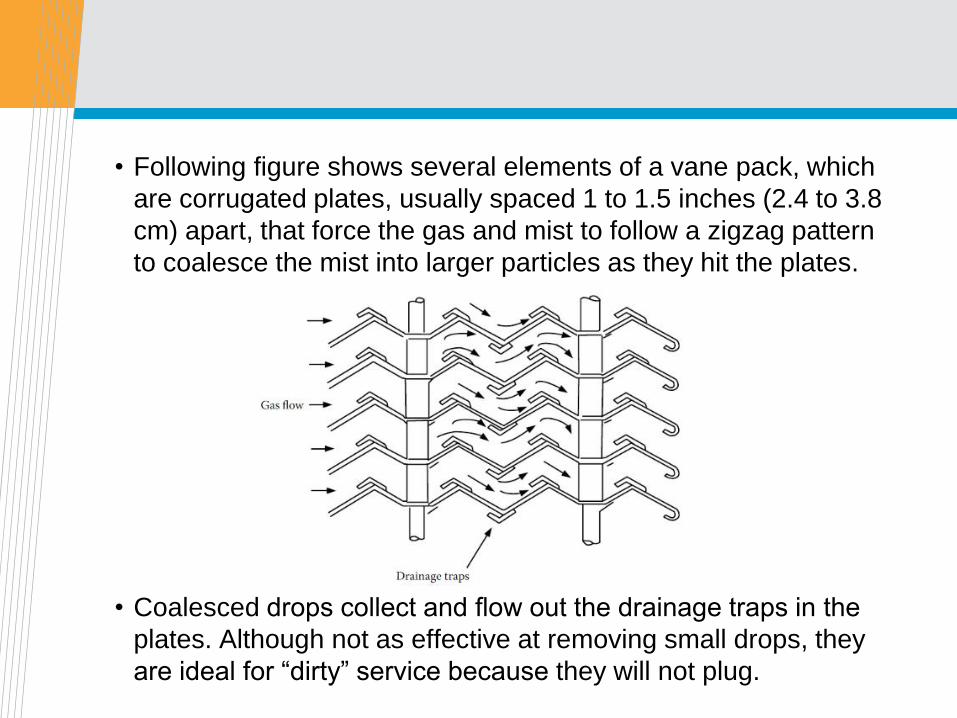
• Following figure shows several elements of a vane pack, which
are corrugated plates, usually spaced 1 to 1.5 inches (2.4 to 3.8
cm) apart, that force the gas and mist to follow a zigzag pattern
to coalesce the mist into larger particles as they hit the plates.
• Coalesced drops collect and flow out the drainage traps in the
plates. Although not as effective at removing small drops, they
are ideal for “dirty” service because they will not plug.
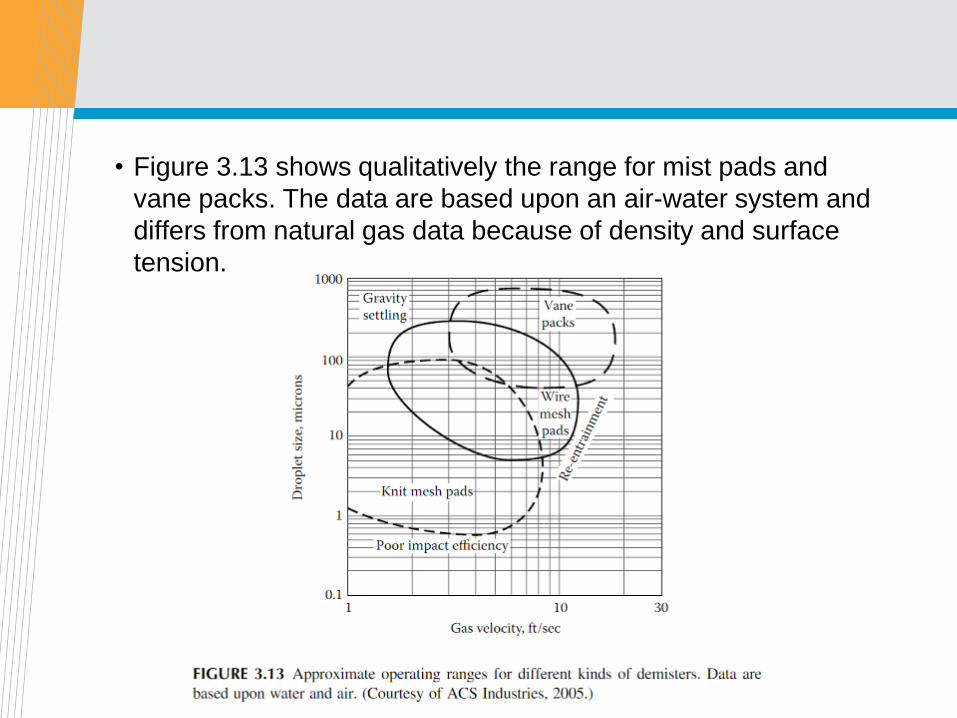
• Figure 3.13 shows qualitatively the range for mist pads and
vane packs. The data are based upon an air-water system and
differs from natural gas data because of density and surface
tension.
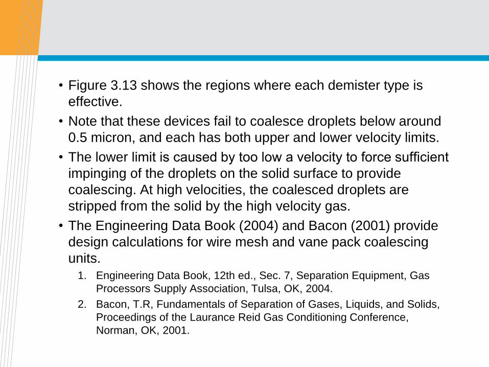
• Figure 3.13 shows the regions where each demister type is
effective.
• Note that these devices fail to coalesce droplets below around
0.5 micron, and each has both upper and lower velocity limits.
• The lower limit is caused by too low a velocity to force sufficient
impinging of the droplets on the solid surface to provide
coalescing. At high velocities, the coalesced droplets are
stripped from the solid by the high velocity gas.
• The Engineering Data Book (2004) and Bacon (2001) provide
design calculations for wire mesh and vane pack coalescing
units.
1. Engineering Data Book, 12th ed., Sec. 7, Separation Equipment, Gas
Processors Supply Association, Tulsa, OK, 2004.
2. Bacon, T.R, Fundamentals of Separation of Gases, Liquids, and Solids,
Proceedings of the Laurance Reid Gas Conditioning Conference,
Norman, OK, 2001.
Liquid collection
• The liquid collection section acts as a holder for the liquids
removed from the gas in the above three separation sections.
• This section also provides for degassing of the liquid and for
water and solids separation from the hydrocarbon phase.
• The most common solid is iron sulfide from corrosion, which
can interfere with the liquid-liquid separation. If a large amount
of water is present, separators often have a “boot,” as shown in
the horizontal separator, at the bottom of the separator for the
water to collect.
• The Engineering Data Book (2004) estimates that retention
times of 3 to 5 minutes are required for hydrocarbon-water
separation by settling.
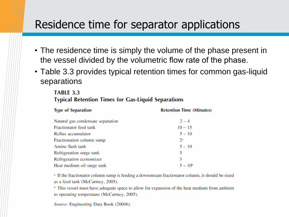
Residence time for separator applications
• The residence time is simply the volume of the phase present in
the vessel divided by the volumetric flow rate of the phase.
• Table 3.3 provides typical retention times for common gas-liquid
separations
Slug catcher configurations
• This section briefly describes two kinds of slug catchers,
manifolded piping and inlet vessels.
• The most difficult part of a slug catcher design is the proper
sizing. Sizing requires knowledge of the largest expected liquid
slug, as liquid pump discharge capacity on the slug catcher will
be trivial compared with the sudden liquid influx.
• Manifolded Piping
: One reason piping is used instead of separators is to minimize
vessel wall thickness. This feature makes piping attractive at
pressures above 500 psi (35bar).
: The simplest slug-catcher design is a single-pipe design that is an
increased diameter on the inlet piping. However, this design requires
special pigs to accommodate the change in line size.
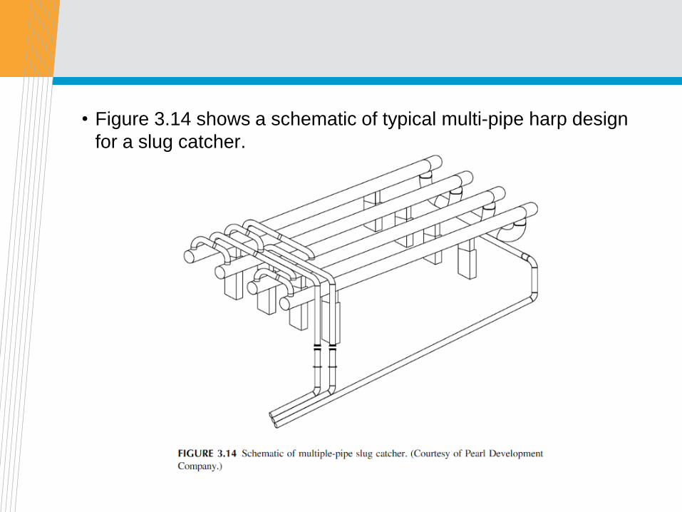
• Figure 3.14 shows a schematic of typical multi-pipe harp design
for a slug catcher.
• The number of pipes varies, depending upon the required
volume and operating pressure. Also, some designs include a
loop line, where some of the incoming gas bypasses the slug
catcher.
• Primary separation occurs when the gas makes the turn at the
inlet and goes down the pipes. Liquid distribution between
pipes can be a problem, and additional lines between the tubes
are often used to balance the liquid levels. In harp designs, the
pipes are sloped so that the liquid drains toward the outlet.
• Gravity settling occurs as the gas flows to the vapor outlet on
the top while the liquid flows out the bottom outlet.
• Pipe diameters are usually relatively small(usually less than 48
inches [120 cm]), so settling distances are short.
• Because manifolded piping is strictly for catching liquid slugs,
demisters are usually installed downstream in scrubbers.
Likewise, liquid goes to other vessels, where degassing and
hydrocarbon-water separation occurs.
• Several advantages to the pipe design include the fact that
design specifications are based upon pipe codes instead of
vessel codes.
• Also, the slug catcher can be underground, which reduces
maintenance costs and insulation costs if the slug catcher
would otherwise need to be heated.
Inlet vessels
• These slug catchers, commonly called inlet receivers, are
simply gas-liquid separators that combine slug catching with
liquid storage.
• They are usually employed where operating pressures are
relatively low or where space is a problem.
• Horizontal vessels are preferred, unless area is limited (as on
offshore platforms), because they provide the highest liquid
surface area.
• Usually two or three vessels are manifolded together to permit
larger volumes and to allow servicing of one vessel without
plant disruption. Length-to-diameter ratios are typically 3:1 to
5:1 to maintain a low gas velocity through the gravity-settling
section.
Comparison of slug catcher configurations
• Land or surface requirements
: If no land constraints apply, piping is attractive. If constraints are
severe, as on offshore platforms, vertical vessels are preferred.
Otherwise horizontal vessels are the best choice.
• Operating pressure.
: If inlet pressures are greater than about 500 psi(35 bar), significant
savings in material costs can be achieved by use of the smaller
diameter piping slug catcher.
• Gas-liquid separation capability.
: Horizontal vessels provide the best separation, whereas piping
provides the least because its main function is to catch liquid slugs.
The large liquid surface area of horizontal vessels provides the best
degassing. Piping has the shortest gas residence time when liquid
levels are properly maintained in the vessels. However, with piping,
small diameter gas scrubbers can be used for demisting.
• Liquid storage.
: Horizontal vessels can act as primary liquid storage, whereas
liquids from vertical vessels and piping must be sent to another
vessel. Regardless of slug catcher used, liquids will go to low-
pressure flash drums to recover light ends.
Applications for transient multiphase simulators
• The uses for transient multiphase flow simulators include:
- Slug flow modeling
- Estimates of the potential for terrain slugging
- Pigging simulation
- Identification of areas with higher corrosion potential, such as water
accumulation in low spots in the line and areas with highly
turbulent/slug flow
- Startup, shutdown and pipeline depressurizing simulations
- Slug catcher design
- Development of operating guidelines
- Real time modeling including leak detection
- Operator training
- Design of control systems for downstream equipment
Flowline depressurization or blowdown
• Depressurization generally refers to the relatively slow
evacuation of a pipeline system. Blowdown generally refers to
the rapid evacuation of a pipeline.
• Depressurizing is usually performed to make the pipeline
available for maintenance or repair. Depressurizing a pipeline
will usually take quite a few hours or even days.
• Pipeline blowdown will generally take a few hours. Blowdown is
sometimes referred to as emergency depressurization. Pipeline
blowdown is often used to minimize the potential for hydrate
formation during a shutdown and to remove the hydrostatic
head rapidly.
• The terms blowdown and depressurization are sometimes used
interchangeably
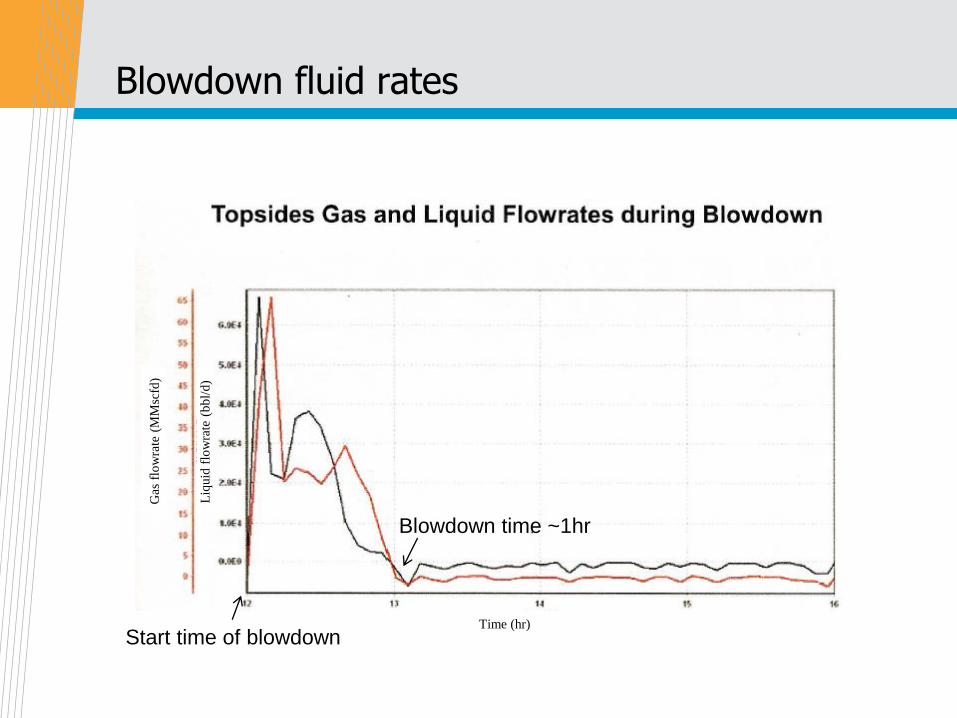
Blowdown fluid rates
Gas
flo
wra
te (
MM
scfd
)
Liq
uid
flo
wra
te (
bb
l/d
)
Time (hr)
Start time of blowdown
Blowdown time ~1hr
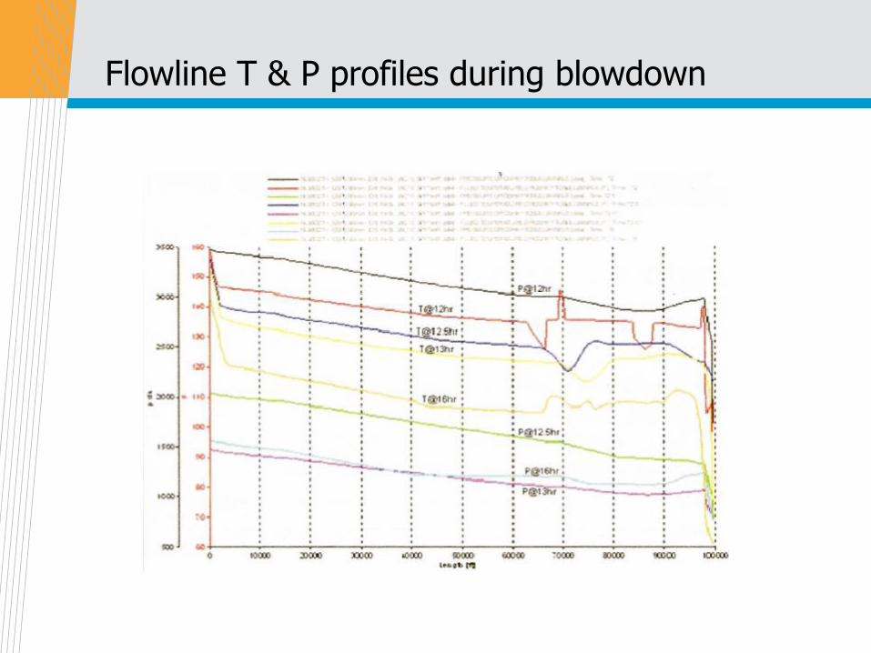
Flowline T & P profiles during blowdown
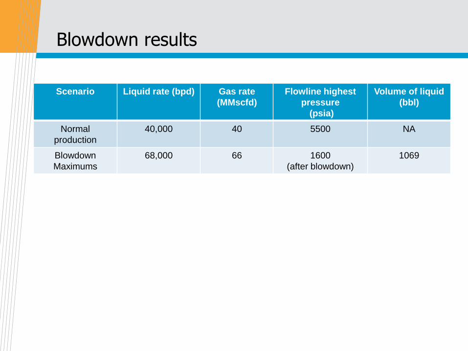
Blowdown results
Scenario Liquid rate (bpd) Gas rate
(MMscfd)
Flowline highest
pressure
(psia)
Volume of liquid
(bbl)
Normal
production
40,000 40 5500 NA
Blowdown
Maximums
68,000 66 1600
(after blowdown)
1069
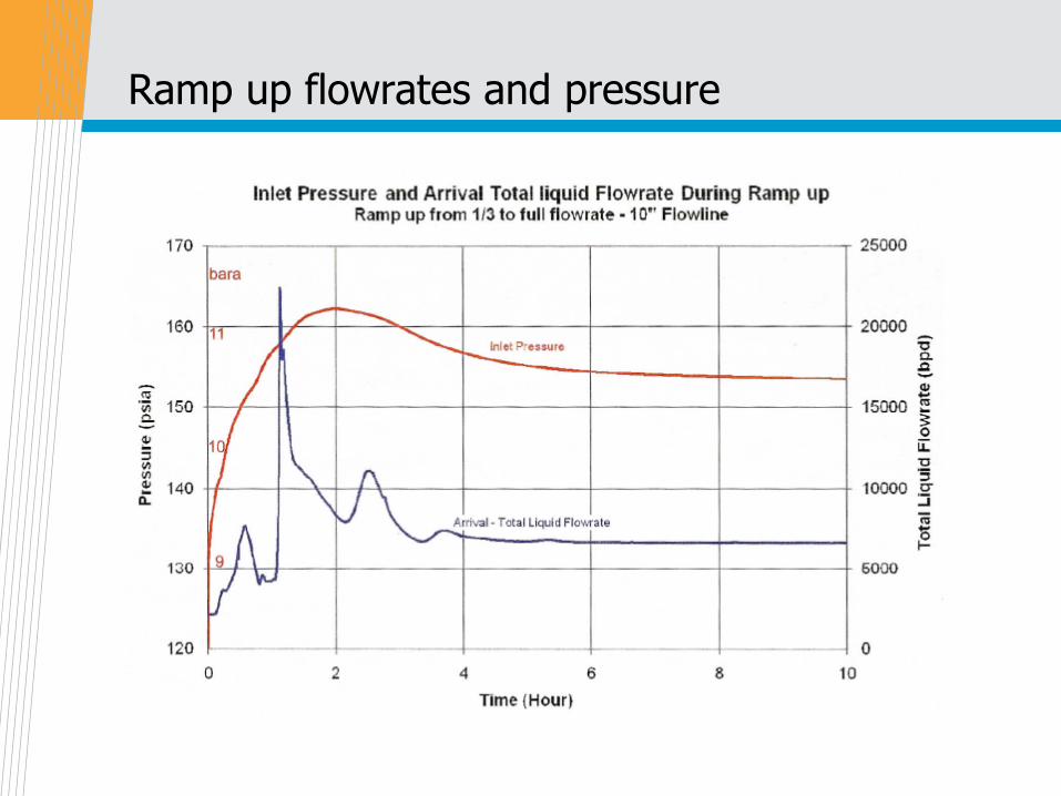
Ramp up flowrates and pressure
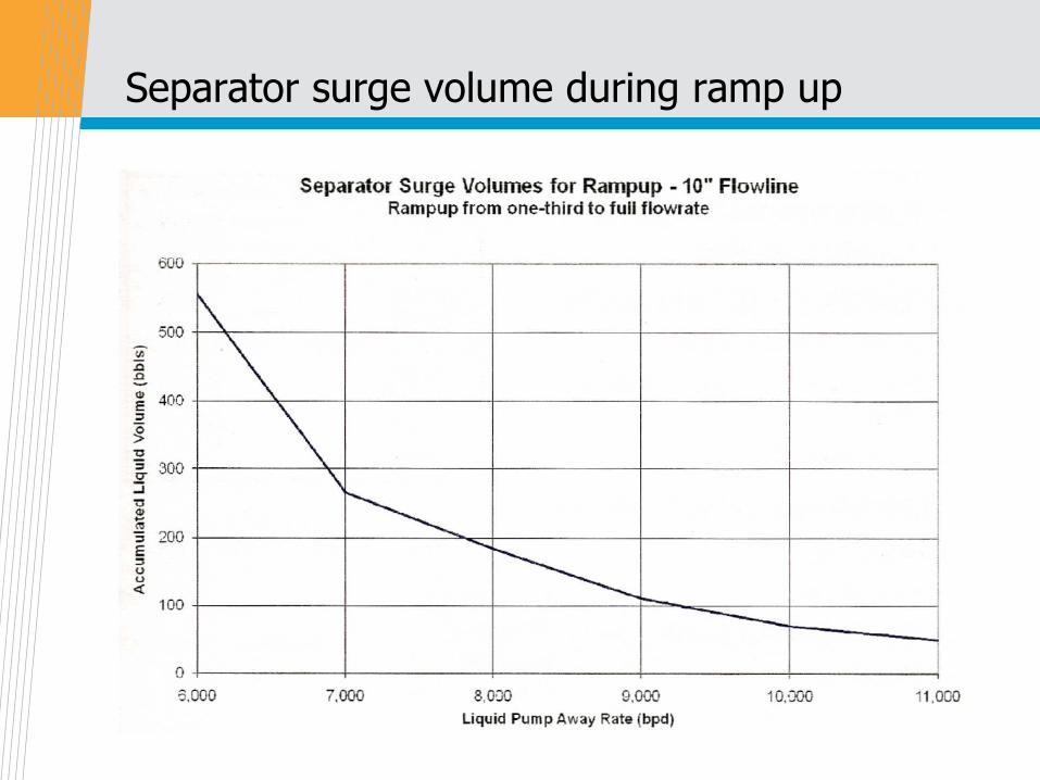
Separator surge volume during ramp up
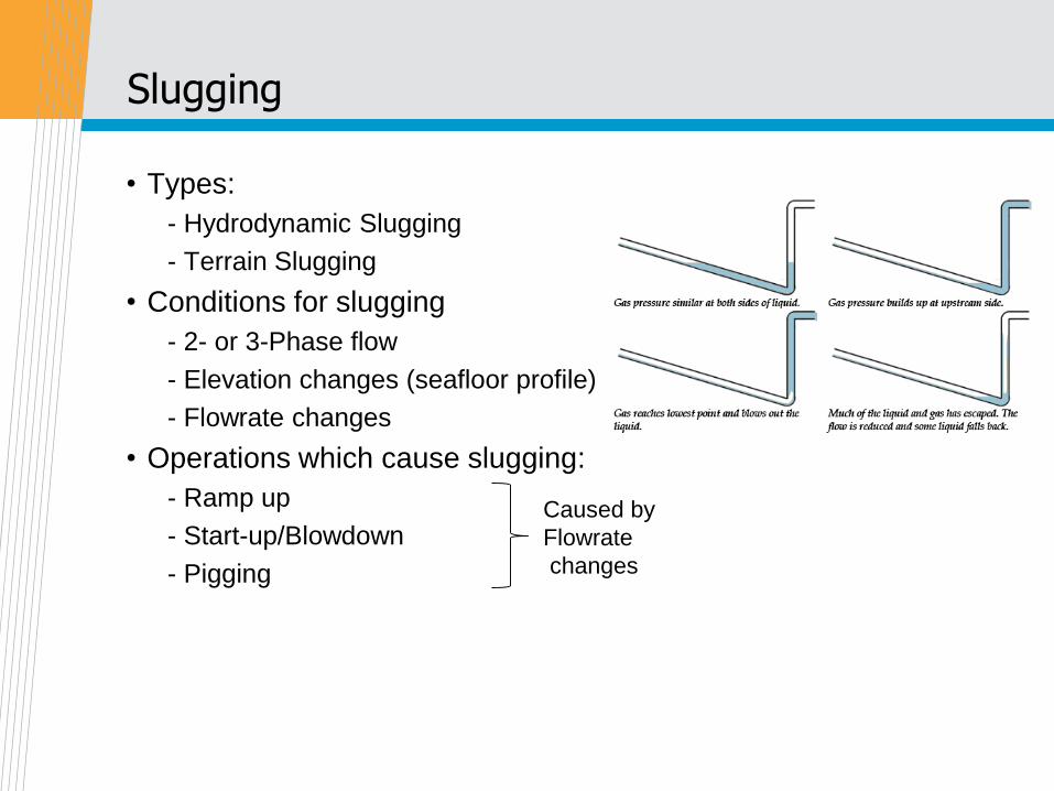
Slugging
• Types:
- Hydrodynamic Slugging
- Terrain Slugging
• Conditions for slugging
- 2- or 3-Phase flow
- Elevation changes (seafloor profile)
- Flowrate changes
• Operations which cause slugging:
- Ramp up
- Start-up/Blowdown
- Pigging
Caused by
Flowrate
changes
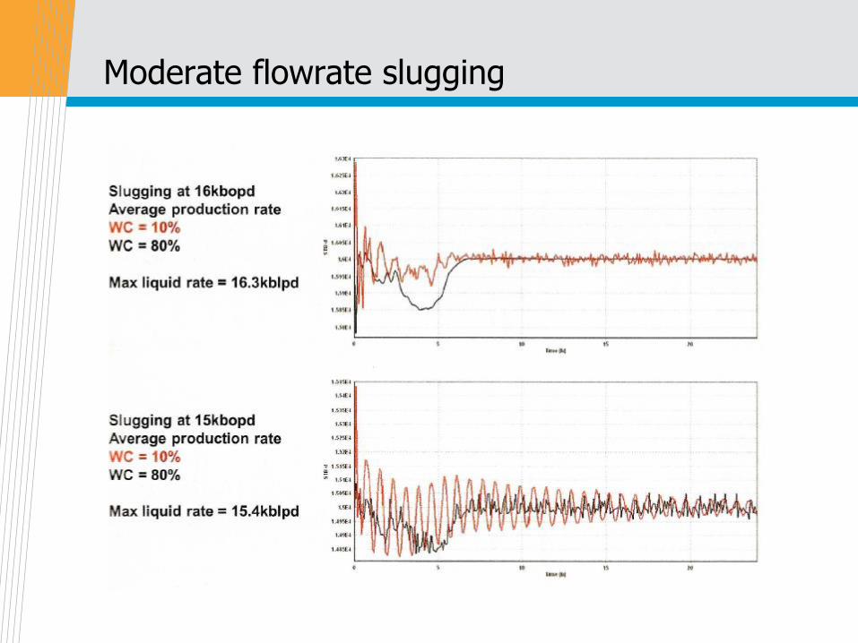
Moderate flowrate slugging
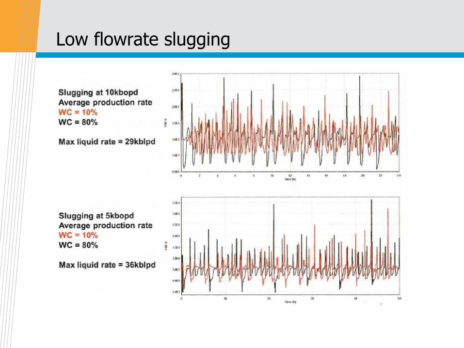
Low flowrate slugging
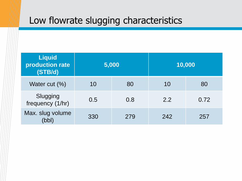
Low flowrate slugging characteristics
Liquid
production rate
(STB/d)
5,000 10,000
Water cut (%) 10 80 10 80
Slugging
frequency (1/hr)0.5 0.8 2.2 0.72
Max. slug volume
(bbl)330 279 242 257
Slugging during ramp up and pigging
• Ramp Up:
: Total Liquids Produced
= holdup at the lower flowrate (minus) holdup at the higher rate.
: The actual liquid production rate during this period will depend on
the fluids, the flowline design and the flow conditions.
• Pigging: The greatest effects on liquid production during pigging
occur with gas condensate flowlines. The entire flowline liquid
holdup (except for the pig by-pass volume) will be produced in
front of the pig.
Need for a slug catcher
• During non-steady state conditions (such as start-up, shutdown,
turndown, and pigging) or when slugging during normal
production occurs (low flowrates)
• The process controllers alone may not be able to sufficiently
compensate for the wide variations in fluid flow rates, vessel
liquid levels, fluid velocities, and system pressure caused by
the slugs
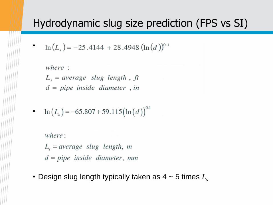
Hydrodynamic slug size prediction (FPS vs SI)
•
•
• Design slug length typically taken as 4 ~ 5 times Ls
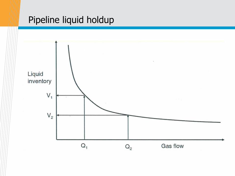
Pipeline liquid holdup
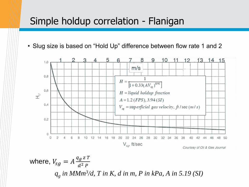
Simple holdup correlation - Flanigan
where, 𝑉𝑠𝑔 = 𝐴𝑞𝑔 𝑧 𝑇
𝑑2 𝑃
qg in MMm3/d, T in K, d in m, P in kPa, A in 5.19 (SI)
• Slug size is based on “Hold Up” difference between flow rate 1 and 2
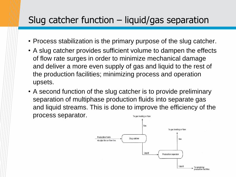
Slug catcher function – liquid/gas separation
• Process stabilization is the primary purpose of the slug catcher.
• A slug catcher provides sufficient volume to dampen the effects
of flow rate surges in order to minimize mechanical damage
and deliver a more even supply of gas and liquid to the rest of
the production facilities; minimizing process and operation
upsets.
• A second function of the slug catcher is to provide preliminary
separation of multiphase production fluids into separate gas
and liquid streams. This is done to improve the efficiency of the
process separator.
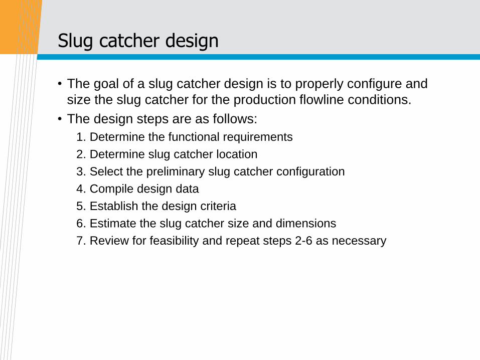
Slug catcher design
• The goal of a slug catcher design is to properly configure and
size the slug catcher for the production flowline conditions.
• The design steps are as follows:
1. Determine the functional requirements
2. Determine slug catcher location
3. Select the preliminary slug catcher configuration
4. Compile design data
5. Establish the design criteria
6. Estimate the slug catcher size and dimensions
7. Review for feasibility and repeat steps 2-6 as necessary
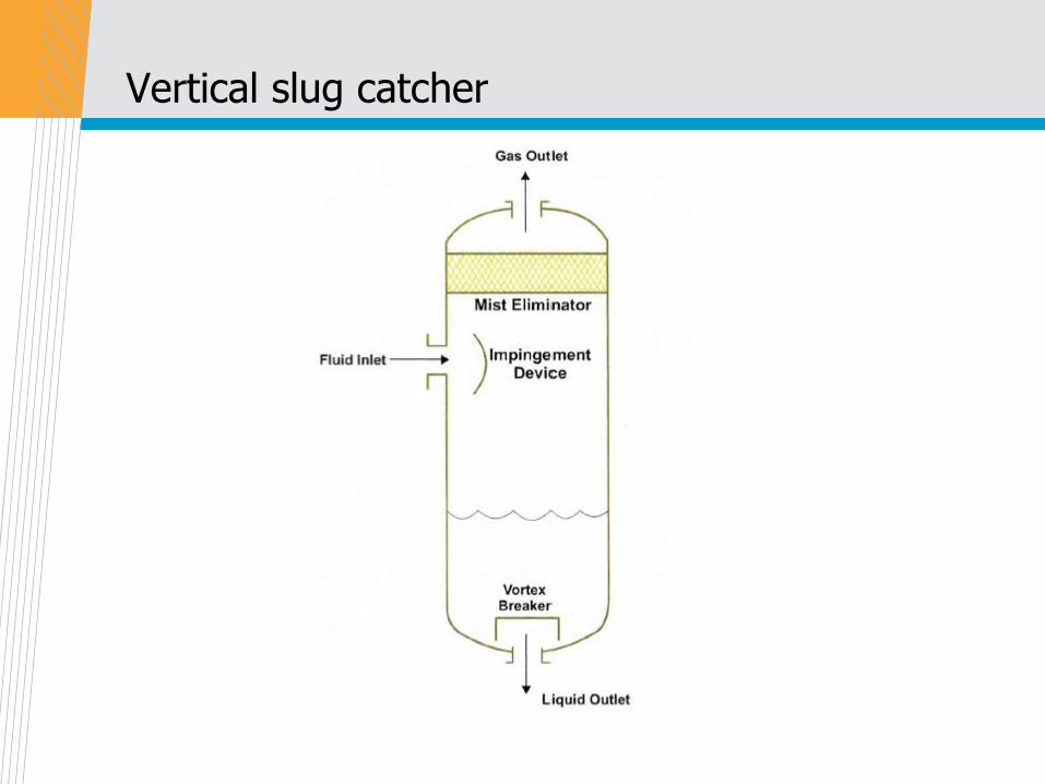
Vertical slug catcher
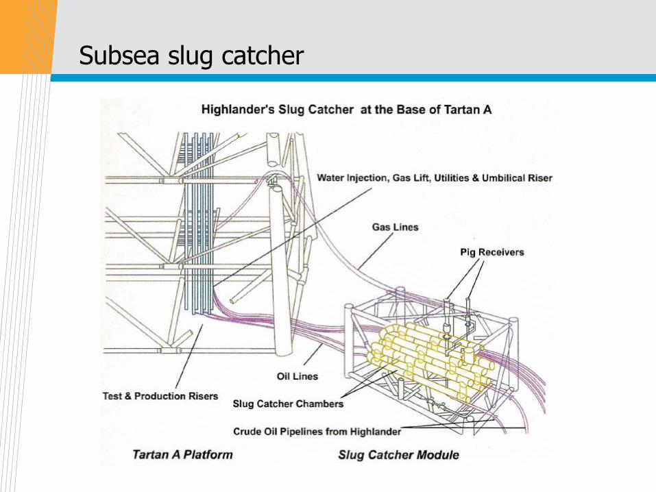
Subsea slug catcher
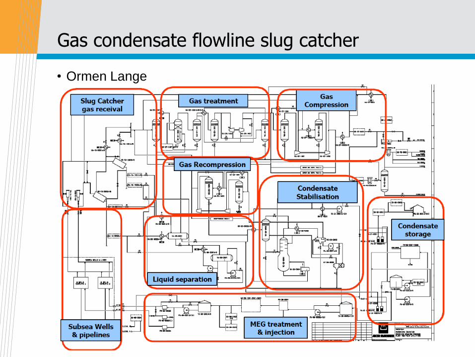
Gas condensate flowline slug catcher
• Ormen Lange

Thank you!