Embed Size (px)
Citation preview
HYSPEC IDT
Introduction to HYSPEC: Overview of the Conceptual Design and Top Level Specifications.
Outline
• Overview of the HYSPEC layout and principal features • Guiding principles of the instrument design • An overview of the important design choices • Instrument specific features and components • Summary, work in progress and open questions
Igor Zaliznyak Neutron Scattering Group, Brookhaven National Laboratory
HYSPEC Instrument Design Working Group
HYSPEC IDT
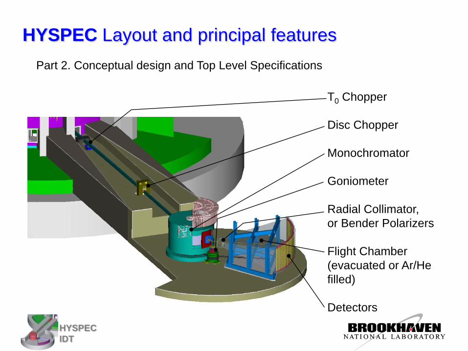
HYSPEC Layout and principal features Part 2. Conceptual design and Top Level Specifications
T0 Chopper Disc Chopper Monochromator Goniometer Radial Collimator, or Bender Polarizers Flight Chamber (evacuated or Ar/He filled) Detectors
HYSPEC IDT
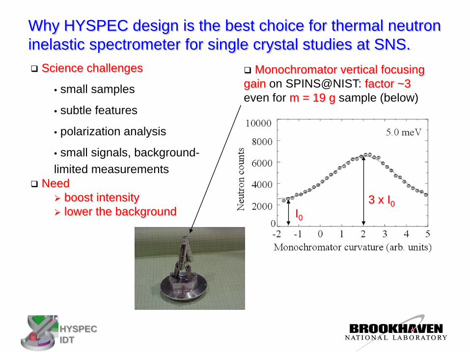
Why HYSPEC design is the best choice for thermal neutron inelastic spectrometer for single crystal studies at SNS.
Monochromator vertical focusing gain on SPINS@NIST: factor ~3 even for m = 19 g sample (below)
Science challenges
• small samples
• subtle features
• polarization analysis
• small signals, background- limited measurements
Need boost intensity lower the background I0
3 x I0
HYSPEC IDT
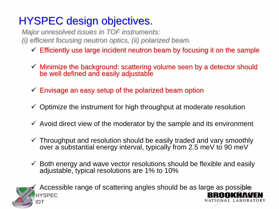
HYSPEC design objectives. Major unresolved issues in TOF instruments: (i) efficient focusing neutron optics, (ii) polarized beam. Efficiently use large incident neutron beam by focusing it on the sample
Minimize the background: scattering volume seen by a detector should
be well defined and easily adjustable
Envisage an easy setup of the polarized beam option
Optimize the instrument for high throughput at moderate resolution
Avoid direct view of the moderator by the sample and its environment
Throughput and resolution should be easily traded and vary smoothly over a substantial energy interval, typically from 2.5 meV to 90 meV
Both energy and wave vector resolutions should be flexible and easily adjustable, typical resolutions are 1% to 10%
Accessible range of scattering angles should be as large as possible
HYSPEC IDT
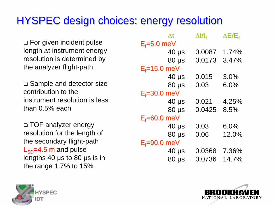
HYSPEC design choices: energy resolution ∆t ∆t/tf ∆E/Ef Ef=5.0 meV 40 μs 0.0087 1.74% 80 μs 0.0173 3.47% Ef=15.0 meV 40 μs 0.015 3.0% 80 μs 0.03 6.0% Ef=30.0 meV 40 μs 0.021 4.25% 80 μs 0.0425 8.5% Ef=60.0 meV 40 μs 0.03 6.0% 80 μs 0.06 12.0% Ef=90.0 meV 40 μs 0.0368 7.36% 80 μs 0.0736 14.7%
For given incident pulse length ∆t instrument energy resolution is determined by the analyzer flight-path
Sample and detector size contribution to the instrument resolution is less than 0.5% each
TOF analyzer energy resolution for the length of the secondary flight-path LSD=4.5 m and pulse lengths 40 μs to 80 μs is in the range 1.7% to 15%
HYSPEC IDT
0 20 40 60 80 100108
109
1010
Neut
ron
curre
nt e
nter
ing
the
guid
e (n
/s)
Incident neutron energy Ei (meV)
Neutron current through 4x12cm2 guide entrance at 1.5 m from the moderator within ∆E=2% of Ei
20 K coupled H2 (NISP interpolation) 20 K coupled H2 (MCSTAS interpolation) H2O (MCSTAS interpolation) MC calculation by E. Iverson
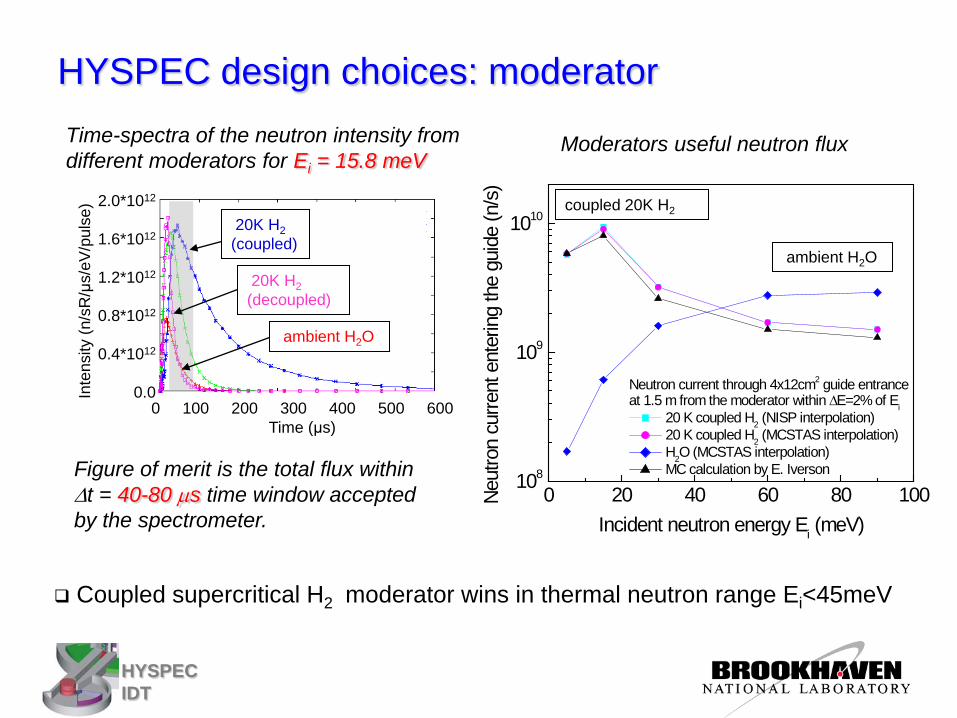
HYSPEC design choices: moderator
2.0*1012
1.6*1012
1.2*1012
0.8*1012
0.4*1012
0.0
20K H2 (decoupled)
Inte
nsity
(n/s
R/μ
s/eV
/pul
se)
Coupled supercritical H2 moderator wins in thermal neutron range Ei<45meV
ambient H2O
0 100 200 300 400 500 600 Time (μs)
Time-spectra of the neutron intensity from different moderators for Ei = 15.8 meV
Moderators useful neutron flux
coupled 20K H2
ambient H2O
Figure of merit is the total flux within ∆t = 40-80 µs time window accepted by the spectrometer.
20K H2 (coupled)
HYSPEC IDT
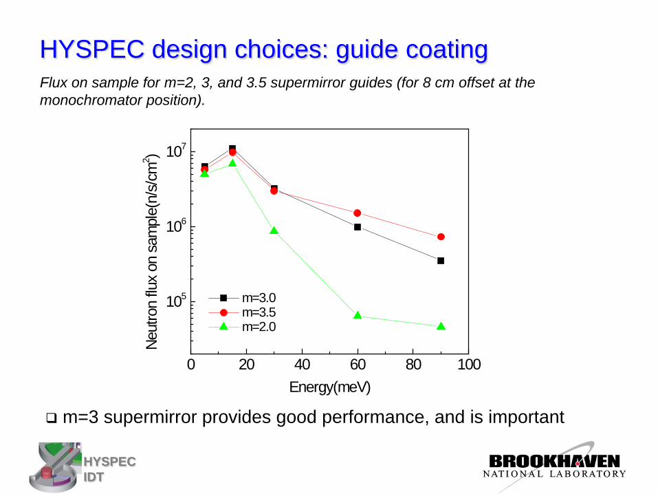
HYSPEC design choices: guide coating
m=3 supermirror provides good performance, and is important
Flux on sample for m=2, 3, and 3.5 supermirror guides (for 8 cm offset at the monochromator position).
0 20 40 60 80 100
105
106
107Ne
utro
n flu
x on
sam
ple(
n/s/
cm2 )
Energy(meV)
m=3.0 m=3.5 m=2.0
HYSPEC IDT
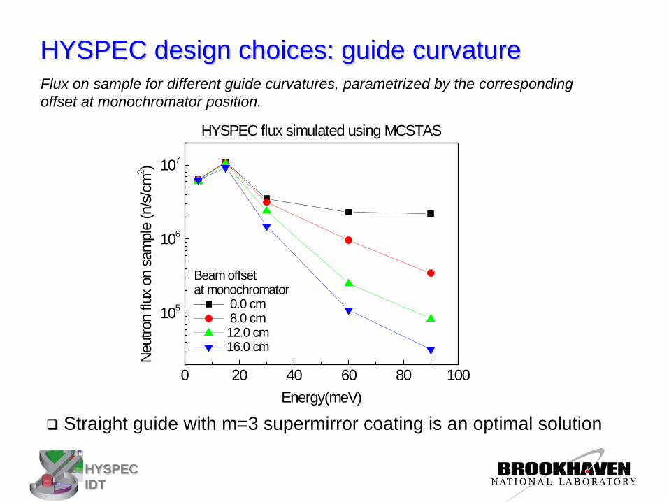
HYSPEC design choices: guide curvature Flux on sample for different guide curvatures, parametrized by the corresponding offset at monochromator position.
Straight guide with m=3 supermirror coating is an optimal solution
0 20 40 60 80 100
105
106
107
HYSPEC flux simulated using MCSTASNe
utro
n flu
x on
sam
ple
(n/s
/cm
2 )
Energy(meV)
Beam offset at monochromator
0.0 cm 8.0 cm 12.0 cm 16.0 cm
HYSPEC IDT
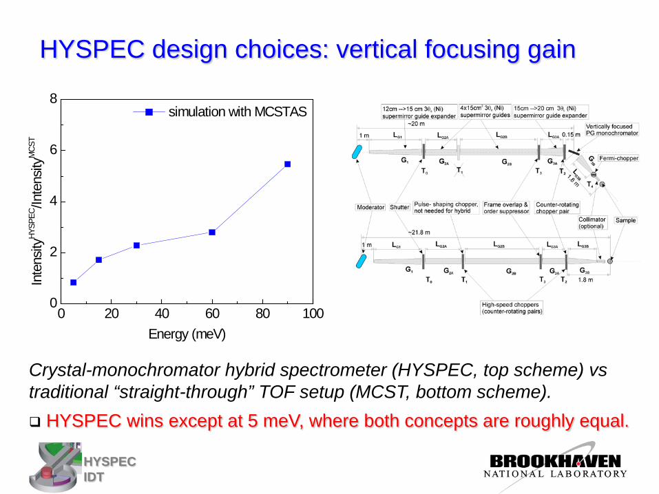
HYSPEC design choices: vertical focusing gain
Crystal-monochromator hybrid spectrometer (HYSPEC, top scheme) vs traditional “straight-through” TOF setup (MCST, bottom scheme). HYSPEC wins except at 5 meV, where both concepts are roughly equal.
0 20 40 60 80 1000
2
4
6
8
Inte
nsity
HYSP
EC/In
tens
ityM
CST
Energy (meV)
simulation with MCSTAS
HYSPEC IDT
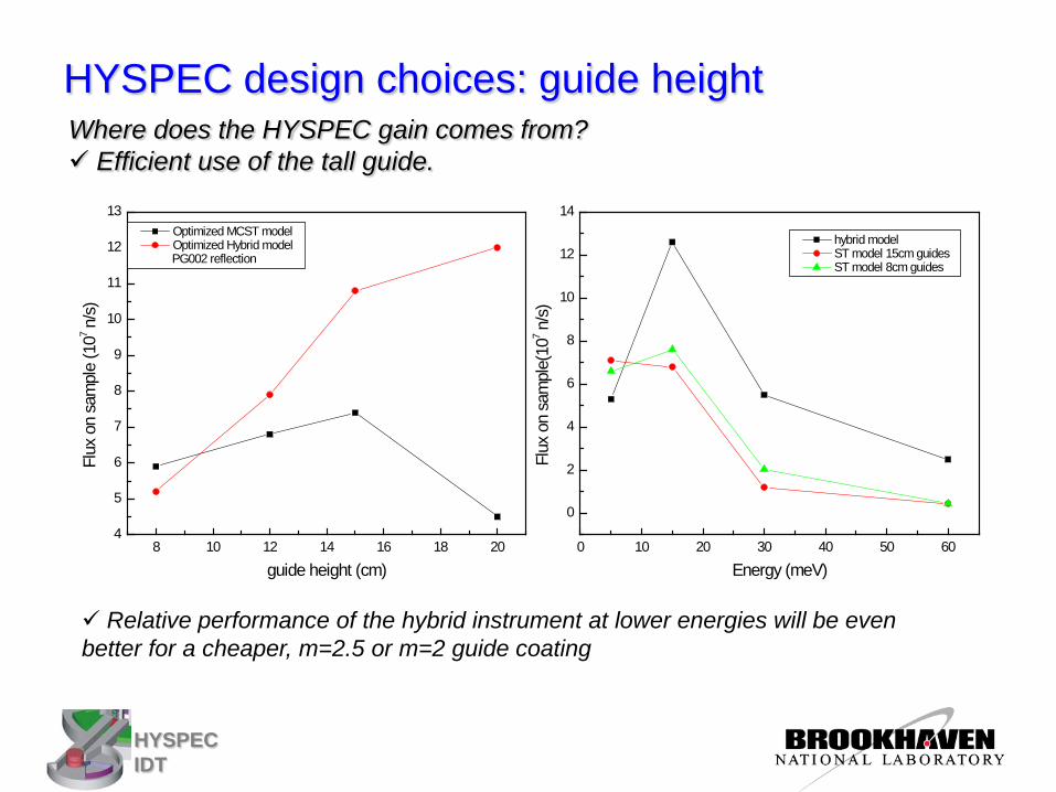
Where does the HYSPEC gain comes from? Efficient use of the tall guide.
Relative performance of the hybrid instrument at lower energies will be even better for a cheaper, m=2.5 or m=2 guide coating
8 10 12 14 16 18 204
5
6
7
8
9
10
11
12
13
Flux
on
sam
ple
(107 n
/s)
guide height (cm)
Optimized MCST model Optimized Hybrid model
PG002 reflection
HYSPEC design choices: guide height
0 10 20 30 40 50 60
0
2
4
6
8
10
12
14
Flux
on
sam
ple(
107 n
/s)
Energy (meV)
hybrid model ST model 15cm guides ST model 8cm guides
HYSPEC IDT
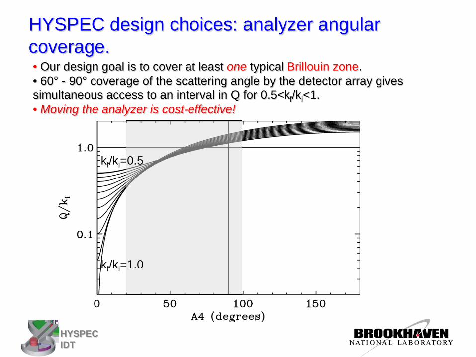
kf/ki=0.5
kf/ki=1.0
• Our design goal is to cover at least one typical Brillouin zone. • 60° - 90° coverage of the scattering angle by the detector array gives simultaneous access to an interval in Q for 0.5<kf/ki<1. • Moving the analyzer is cost-effective!
HYSPEC design choices: analyzer angular coverage.
HYSPEC IDT
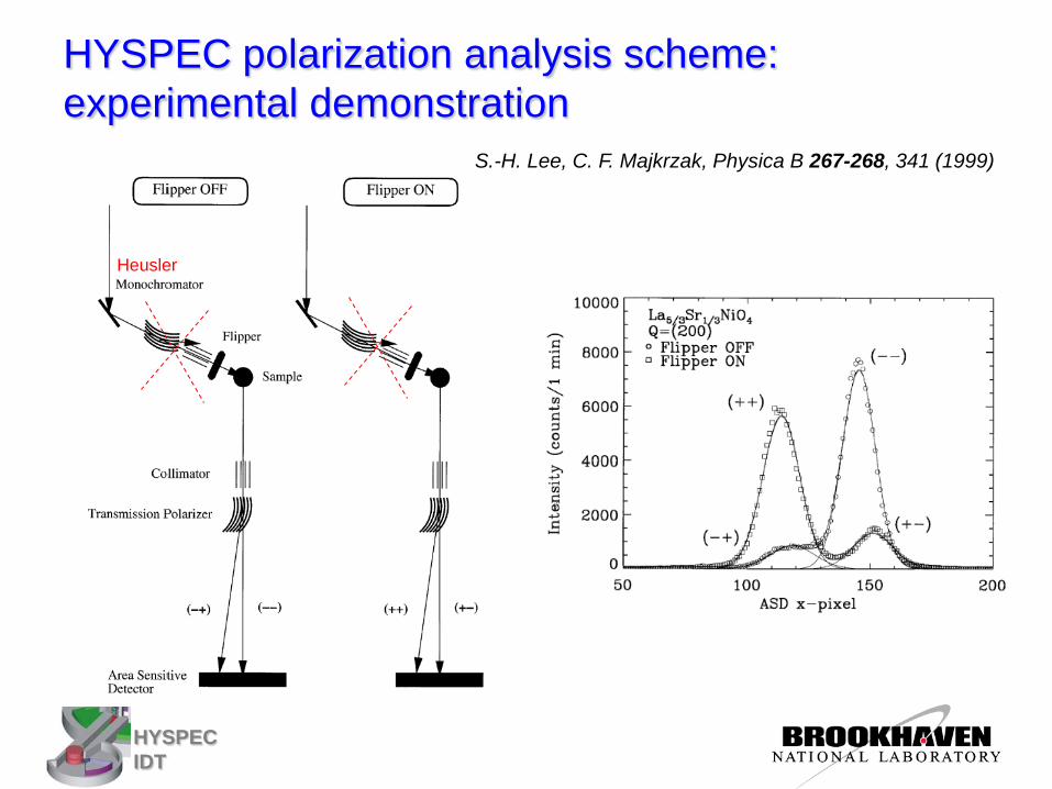
HYSPEC polarization analysis scheme: experimental demonstration
S.-H. Lee, C. F. Majkrzak, Physica B 267-268, 341 (1999)
Heusler
HYSPEC IDT
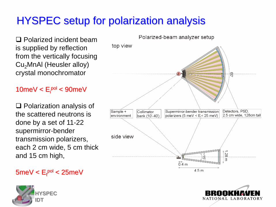
HYSPEC setup for polarization analysis Polarized incident beam is supplied by reflection from the vertically focusing Cu2MnAl (Heusler alloy) crystal monochromator
10meV < Ei
pol < 90meV
Polarization analysis of the scattered neutrons is done by a set of 11-22 supermirror-bender transmission polarizers, each 2 cm wide, 5 cm thick and 15 cm high,
5meV < Ef
pol < 25meV
HYSPEC IDT
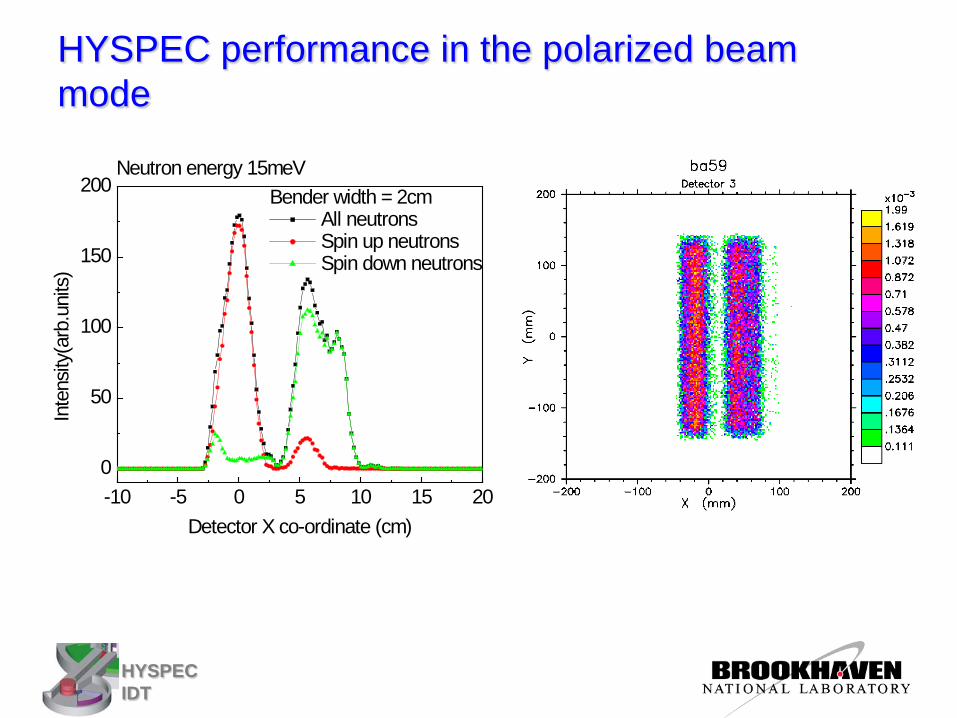
HYSPEC performance in the polarized beam mode
-10 -5 0 5 10 15 200
50
100
150
200Neutron energy 15meV
Inte
nsity
(arb
.uni
ts)
Detector X co-ordinate (cm)
Bender width = 2cm All neutrons Spin up neutrons Spin down neutrons
HYSPEC IDT
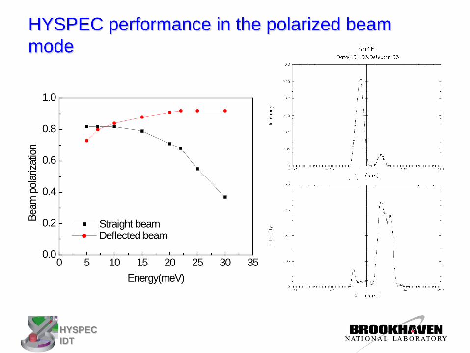
HYSPEC performance in the polarized beam mode
0 5 10 15 20 25 30 350.0
0.2
0.4
0.6
0.8
1.0
Beam
pol
ariza
tion
Energy(meV)
Straight beam Deflected beam
HYSPEC IDT
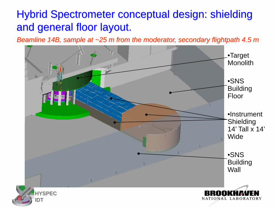
•Target Monolith
•SNS Building Floor
•Instrument Shielding 14’ Tall x 14’ Wide
•SNS Building Wall
Beamline 14B, sample at ~25 m from the moderator, secondary flightpath 4.5 m
Hybrid Spectrometer conceptual design: shielding and general floor layout.
HYSPEC IDT
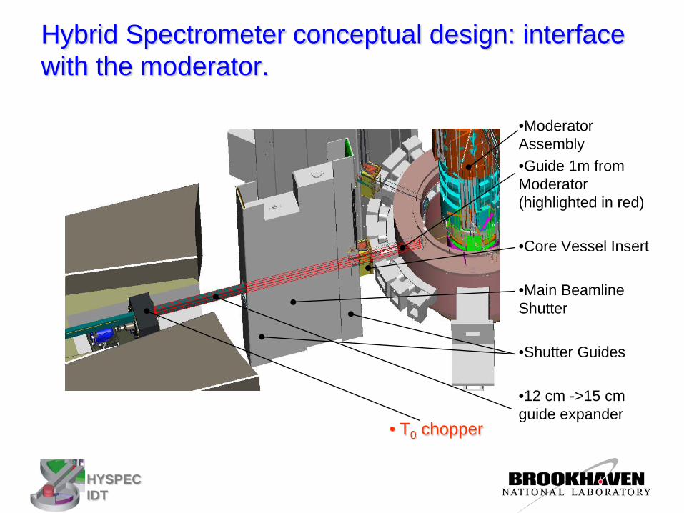
•Moderator Assembly •Guide 1m from Moderator (highlighted in red)
•Core Vessel Insert
•Main Beamline Shutter
•Shutter Guides
•12 cm ->15 cm guide expander
Hybrid Spectrometer conceptual design: interface with the moderator.
• T0 chopper
HYSPEC IDT
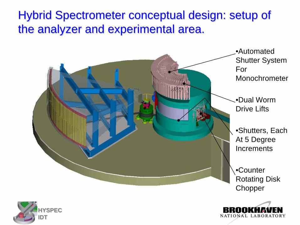
•Automated Shutter System For Monochrometer
•Dual Worm Drive Lifts
•Shutters, Each At 5 Degree Increments
•Counter Rotating Disk Chopper
Hybrid Spectrometer conceptual design: setup of the analyzer and experimental area.
HYSPEC IDT
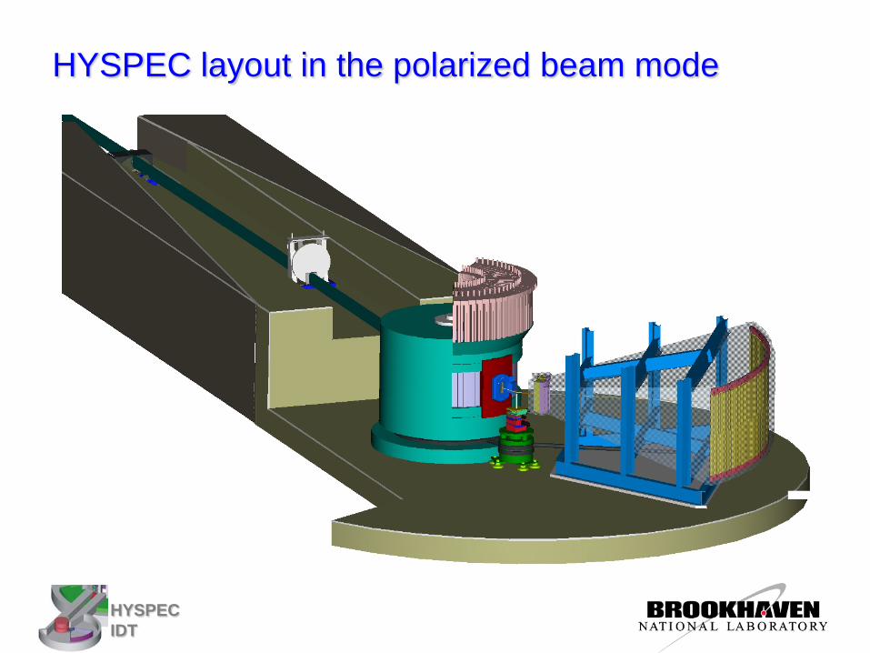
HYSPEC layout in the polarized beam mode
HYSPEC IDT
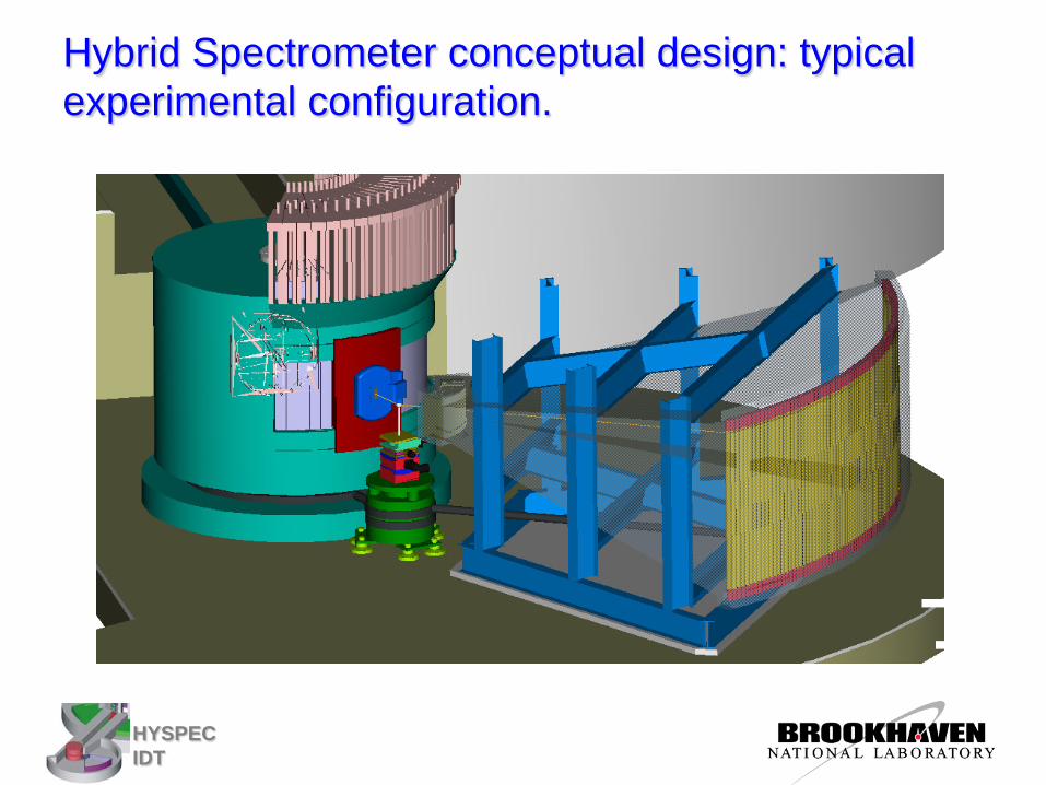
Hybrid Spectrometer conceptual design: typical experimental configuration.
HYSPEC IDT
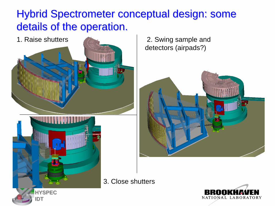
1. Raise shutters 2. Swing sample and detectors (airpads?)
3. Close shutters
Hybrid Spectrometer conceptual design: some details of the operation.
HYSPEC IDT
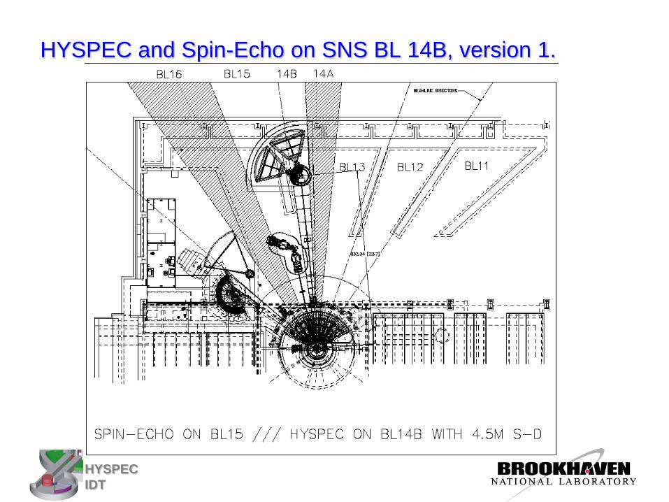
HYSPEC and Spin-Echo on SNS BL 14B, version 1.
HYSPEC IDT
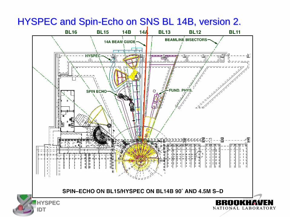
HYSPEC and Spin-Echo on SNS BL 14B, version 2.
HYSPEC IDT
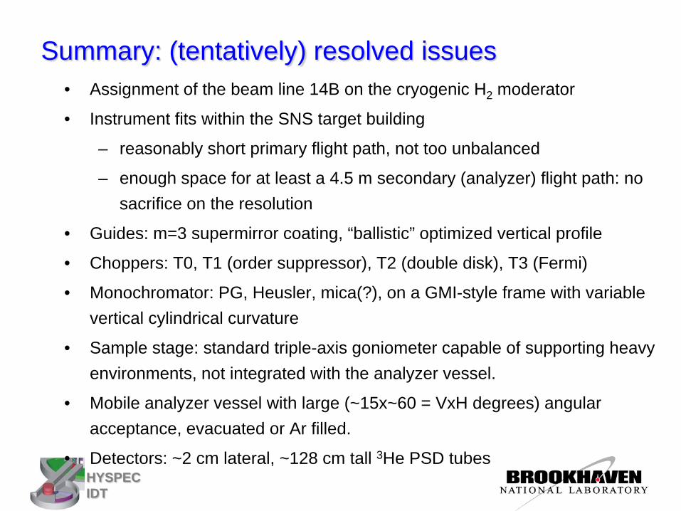
Summary: (tentatively) resolved issues • Assignment of the beam line 14B on the cryogenic H2 moderator
• Instrument fits within the SNS target building
– reasonably short primary flight path, not too unbalanced
– enough space for at least a 4.5 m secondary (analyzer) flight path: no sacrifice on the resolution
• Guides: m=3 supermirror coating, “ballistic” optimized vertical profile
• Choppers: T0, T1 (order suppressor), T2 (double disk), T3 (Fermi)
• Monochromator: PG, Heusler, mica(?), on a GMI-style frame with variable vertical cylindrical curvature
• Sample stage: standard triple-axis goniometer capable of supporting heavy environments, not integrated with the analyzer vessel.
• Mobile analyzer vessel with large (~15x~60 = VxH degrees) angular acceptance, evacuated or Ar filled.
• Detectors: ~2 cm lateral, ~128 cm tall 3He PSD tubes
HYSPEC IDT
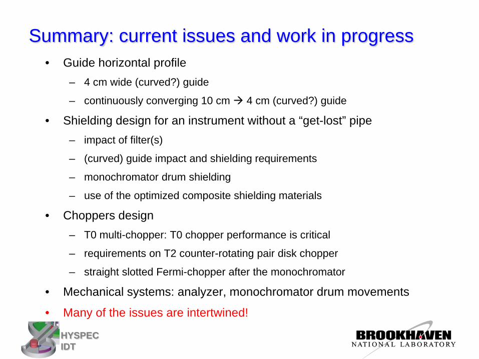
Summary: current issues and work in progress • Guide horizontal profile
– 4 cm wide (curved?) guide
– continuously converging 10 cm 4 cm (curved?) guide
• Shielding design for an instrument without a “get-lost” pipe – impact of filter(s)
– (curved) guide impact and shielding requirements
– monochromator drum shielding
– use of the optimized composite shielding materials
• Choppers design – T0 multi-chopper: T0 chopper performance is critical
– requirements on T2 counter-rotating pair disk chopper
– straight slotted Fermi-chopper after the monochromator
• Mechanical systems: analyzer, monochromator drum movements
• Many of the issues are intertwined!
HYSPEC IDT
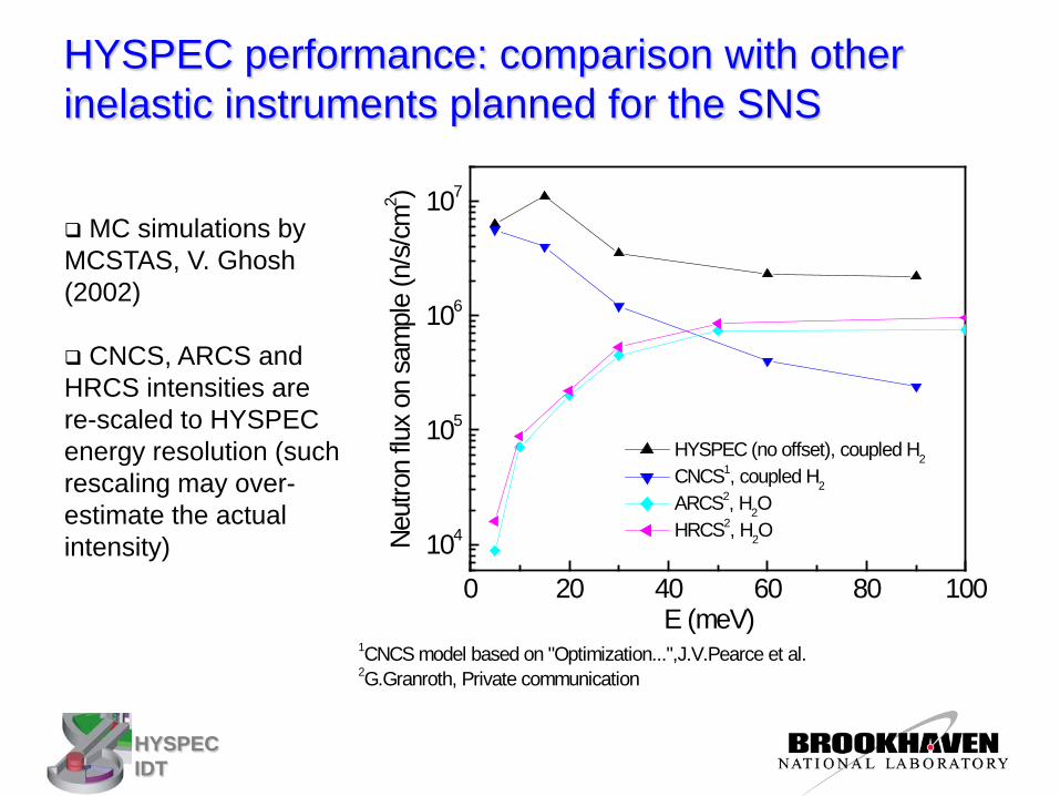
HYSPEC performance: comparison with other inelastic instruments planned for the SNS
MC simulations by MCSTAS, V. Ghosh (2002)
CNCS, ARCS and HRCS intensities are re-scaled to HYSPEC energy resolution (such rescaling may over-estimate the actual intensity)
0 20 40 60 80 100104
105
106
107
1CNCS model based on "Optimization...",J.V.Pearce et al. 2G.Granroth, Private communication
Neut
ron
flux
on s
ampl
e (n
/s/c
m2 )
E (meV)
HYSPEC (no offset), coupled H2
CNCS1, coupled H2 ARCS2, H2O HRCS2, H2O
HYSPEC IDT
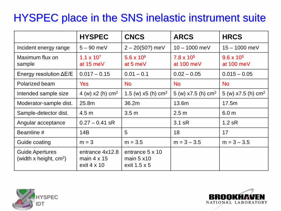
HYSPEC place in the SNS inelastic instrument suite HYSPEC CNCS ARCS HRCS
Incident energy range 5 – 90 meV 2 – 20(50?) meV 10 – 1000 meV 15 – 1000 meV
Maximum flux on sample
1.1 x 10⁷ at 15 meV
5.6 x 10⁶ at 5 meV
7.8 x 10⁵ at 100 meV
9.6 x 10⁵ at 100 meV
Energy resolution ΔE/E 0.017 – 0.15 0.01 – 0.1 0.02 – 0.05 0.015 – 0.05
Polarized beam Yes No No No
Intended sample size 4 (w) x2 (h) cm2 1.5 (w) x5 (h) cm2 5 (w) x7.5 (h) cm2 5 (w) x7.5 (h) cm2
Moderator-sample dist. 25.8m 36.2m 13.6m 17.5m
Sample-detector dist. 4.5 m 3.5 m 2.5 m 6.0 m
Angular acceptance 0.27 – 0.41 sR 3.1 sR 1.2 sR
Beamline # 14B 5 18 17
Guide coating m = 3 m = 3.5 m = 3 – 3.5 m = 3 – 3.5
Guide Apertures (width x height, cm2)
entrance 4x12.8 main 4 x 15 exit 4 x 10
entrance 5 x 10 main 5 x10 exit 1.5 x 5
HYSPEC IDT
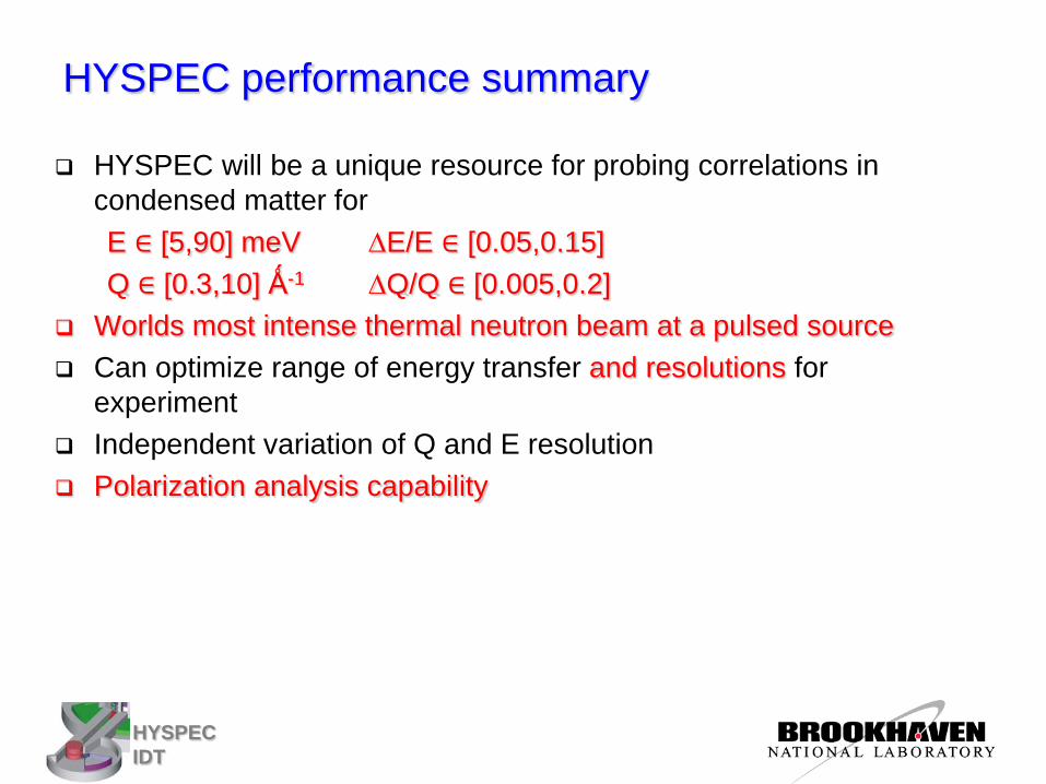
HYSPEC performance summary
HYSPEC will be a unique resource for probing correlations in condensed matter for E ∈ [5,90] meV ∆E/E ∈ [0.05,0.15] Q ∈ [0.3,10] Ǻ-1 ∆Q/Q ∈ [0.005,0.2]
Worlds most intense thermal neutron beam at a pulsed source Can optimize range of energy transfer and resolutions for
experiment Independent variation of Q and E resolution Polarization analysis capability
HYSPEC IDT
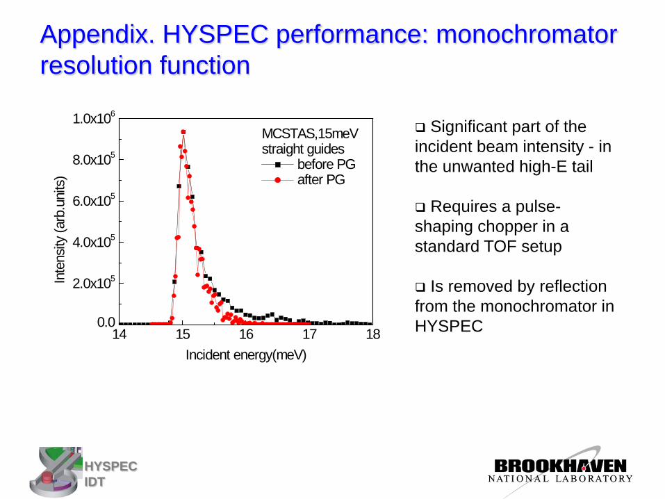
Appendix. HYSPEC performance: monochromator resolution function
14 15 16 17 180.0
2.0x10⁵
4.0x10⁵
6.0x10⁵
8.0x10⁵
1.0x10⁶
Inte
nsity
(arb
.uni
ts)
Incident energy(meV)
MCSTAS,15meVstraight guides
before PG after PG
Significant part of the incident beam intensity - in the unwanted high-E tail
Requires a pulse-shaping chopper in a standard TOF setup
Is removed by reflection from the monochromator in HYSPEC
HYSPEC IDT
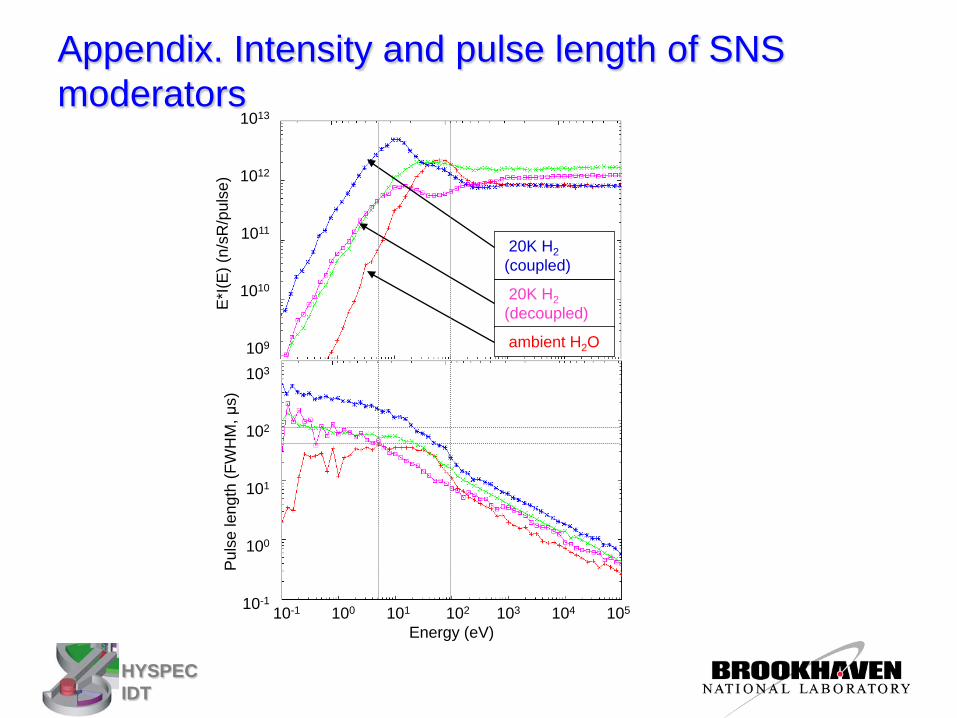
Appendix. Intensity and pulse length of SNS moderators
1013
1012
1011
1010
109
103
102
101
100
10-1 10-1 100 101 102 103 104 105
Energy (eV)
E*I(E
) (n/
sR/p
ulse
) Pu
lse
leng
th (F
WH
M, μ
s)
20K H2 (decoupled)
20K H2 (coupled)
ambient H2O