Embed Size (px)
Citation preview

Introduction to Geotextiles in Pavement & Drainage Applications Course No: C02-019
Credit: 2 PDH
J. Paul Guyer, P.E., R.A., Fellow ASCE, Fellow AEI
Continuing Education and Development, Inc. 9 Greyridge Farm Court Stony Point, NY 10980 P: (877) 322-5800 F: (877) 322-4774 [email protected]
J. Paul Guyer, P.E., R.A. Paul Guyer is a registered civil engineer, mechanical engineer, fire protection engineer, and architect with over 35 years experience in the design of buildings and related infrastructure. For an additional 9 years he was a senior advisor to the California Legislature on infrastructure and capital outlay issues. He is a graduate of Stanford University and has held numerous national, state and local positions with the American Society of Civil Engineers and National Society of Professional Engineers.
An Introduction to Geotextiles in Pavement and Drainage Applications
G u y e r P a r t n e r s4 4 2 4 0 C l u b h o u s e D r i v e
E l M a c e r o , C A 9 5 6 1 8( 5 3 0 ) 7 7 5 8 - 6 6 3 7
j p g u y e r @ p a c b e l l . n e t
© J. Paul Guyer 2009 1

This course is adapted from the Unified Facilities Criteria of the United States government, which is in the public domain, has unlimited distribution and is not copyrighted.
© J. Paul Guyer 2009 2

CONTENTS
1. GEOTEXTILES IN GENERAL 1.1 Scope 1.2 Geotextile Types and Construction 1.3 Geotextile Durability 1.4 Geotextile Functions and Applications 2. PAVEMENT APPLICATIONS 2.1 Applications 2.2 Paved Surface Rehabilitation 2.3 Reflective Crack Treatment for Pavements 2.4 Separation and Reinforcement 2.5 Design for Separation 2.6 Geotextile Survivability 2.7 Design for Reinforcement 3. DRAINAGE APPLICATIONS 3.1 Water Control 3.2 Granular Drain Performance 3.3 Geotextile Characteristics Influencing Filter Functions 3.4 Piping Resistance 3.5 Permeability 3.6 Other Filter Considerations 3.7 Strength Requirements 3.8 Design and Construction Considerations
© J. Paul Guyer 2009 3
1. GEOTEXTILES IN GENERAL 1.1 Scope This course covers physical properties, functions, design methods, design details and
construction procedures for geotextiles as used in pavements and drainage
applications. Geotextile functions described include pavements, filtration and drainage.
This course does not cover the use of other geosynthetics such as geogrids, geonets,
geomembranes, plastic strip drains, composite products and products made from
natural cellulose fibers.
1.2 Geotextile Types and Construction 1.2.1 Materials. Geotextiles are made from polypropylene, polyester, polyethylene,
polyamide (nylon), polyvinylidene chloride, and fiberglass. Polypropylene and polyester
are the most used. Sewing thread for geotextiles is made from Kevlar or any of the
above polymers. The physical properties of these materials can be varied by the use of
additives in the composition and by changing the processing methods used to form the
molten material into filaments. Yarns are formed from fibers which have been bundled
and twisted together, a process also referred to as spinning. (This reference is different
from the term spinning as used to denote the process of extruding filaments from a
molten material.) Yarns may be composed of very long fibers (filaments) or relatively
short pieces cut from filaments (staple fibers).
1.2.2 Geotextile Manufacture.
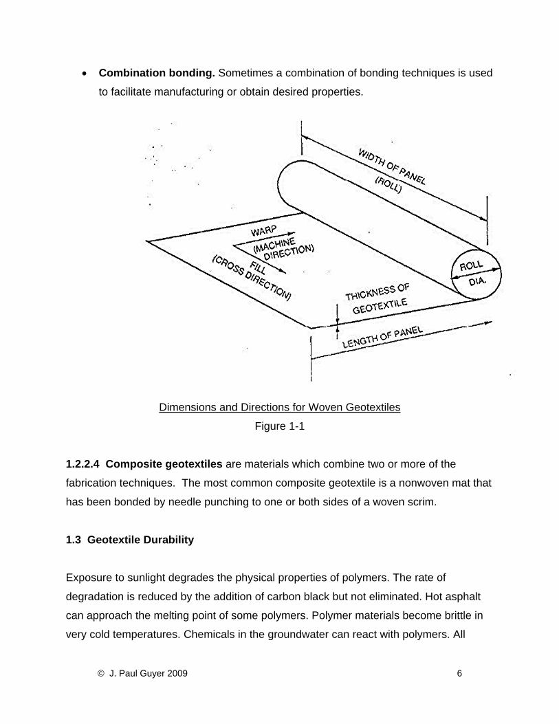
1.2.2.1 In woven construction, the warp yarns, which run parallel with the length of
the panel (machine direction), are interlaced with yarns called fill or filling yarns, which
run perpendicular to the length of the panel (cross direction as shown in Figure 1-1).
Woven construction produces geotextiles with high strengths and moduli in the warp
and fill directions and low elongations at rupture. The modulus varies depending on the
rate and the direction in which the geotextile is loaded. When woven geotextiles are
pulled on a bias, the modulus decreases, although the ultimate breaking strength may
© J. Paul Guyer 2009 4
increase. The construction can be varied so that the finished geotextile has equal or
different strengths in the warp and fill directions. Woven construction produces
geotextiles with a simple pore structure and narrow range of pore sizes or openings
between fibers. Woven geotextiles are commonly plain woven, but are sometimes made
by twill weave or leno weave (a very open type of weave). Woven geotextiles can be
composed of monofilaments or multifilament yarns. Multifilament woven construction
produces the highest strength and modulus of all the constructions but are also the
highest cost. A monofilament variant is the slit-film or ribbon filament woven geotextile.
The fibers are thin and flat and made by cutting sheets of plastic into narrow strips. This
type of woven geotextile is relatively inexpensive and is used for separation, i.e., the
prevention of intermixing of two materials such as aggregate and fine-grained
soil.
1.2.2.2 Manufacturers literature and textbooks should be consulted for greater
description of woven and knitted geotextile manufacturing processes which continue to
be expanded.
1.2.2.3 Nonwoven geotextiles are formed by a process other than weaving or knitting,
and they are generally thicker than woven products. These geotextiles may be made
either from continuous filaments or from staple fibers. The fibers are generally oriented
randomly within the plane of the geotextile but can be given preferential orientation.
In the spun-bonding process, filaments are extruded, and laid directly on a moving belt
to form the mat, which is then bonded by one of the processes described below.
• Needle punching. Bonding by needle punching involves pushing many barbed
needles through one or several layers of a fiber mat normal to the plane of the
geotextile. The process causes the fibers to be mechanically entangled. The
resulting geotextile has the appearance of a felt mat.
• Heat bonding. This is done by incorporating fibers of the same polymer type but
having different melting points in the mat, or by using heterofilaments, that is,
fibers composed of one type of polymer on the inside and covered or sheathed
with a polymer having a lower melting point.
• Resin bonding. Resin is introduced into the fiber mat, coating the fibers and
bonding the contacts between fibers.
© J. Paul Guyer 2009 5
• Combination bonding. Sometimes a combination of bonding techniques is used
to facilitate manufacturing or obtain desired properties.
Dimensions and Directions for Woven Geotextiles
Figure 1-1
1.2.2.4 Composite geotextiles are materials which combine two or more of the
fabrication techniques. The most common composite geotextile is a nonwoven mat that
has been bonded by needle punching to one or both sides of a woven scrim.
1.3 Geotextile Durability Exposure to sunlight degrades the physical properties of polymers. The rate of
degradation is reduced by the addition of carbon black but not eliminated. Hot asphalt
can approach the melting point of some polymers. Polymer materials become brittle in
very cold temperatures. Chemicals in the groundwater can react with polymers. All
© J. Paul Guyer 2009 6
polymers gain water with time if water is present. High pH water can be harsh on
polyesters while low pH water can be harsh on polyamides. Where a chemically
unusual environment exists, laboratory test data on effects of exposure of the geotextile
to this environment should be sought. Experience with geotextiles in place spans only
about 30 years. All of these factors should be considered in selecting or specifying
acceptable geotextile materials. Where long duration integrity of the material is critical to
life safety and where the in-place material cannot easily be periodically inspected or
easily replaced if it should become degraded (for example filtration and/or drainage
functions within an earth dam), current practice is to use only geologic materials (which
are orders of magnitude more resistant to these weathering effects than polyesters).
1.4 Geotextile Functions and Applications. 1.4.1 Functions. Geotextiles perform one or more basic functions: filtration, drainage,
separation, erosion control, sediment control, reinforcement, and (when impregnated
with asphalt) moisture barrier. In any one application, a geotextile may be performing
several of these functions.
1.4.2 Filtration. The use of geotextiles in filter applications is probably the oldest, the
most widely known, and the most used function of geotextiles. In this application, the
geotextile is placed in contact with and down gradient of soil to be drained. The plane of
to the expected direction of water flow. The capacity for flow of water normal to the
plane of the geotextile is referred to as permittivity. Water and any particles suspended
in the water which are smaller than a given size flow through the geotextile.
Those soil particles larger than that size are stopped and prevented from being carried
away. The geotextile openings should be sized to prevent soil particle movement. The
geotextiles substitute for and serve the same function as the traditional granular filter.
Both the granular filter and the geotextile filter must allow water (or gas) to pass without
significant buildup of hydrostatic pressure. A geotextile-lined drainage trench along the
edge of a road pavement is an example using a geotextile as a filter. Most geotextiles
are capable of performing this function. Slit film geotextiles are not preferred because
© J. Paul Guyer 2009 7
opening sizes are unpredictable. Long term clogging is a concern when geotextiles are
used for filtration.
1.4.3 Drainage. When functioning as a drain, a geotextile acts as a conduit for the
movement of liquids or gases in the plane of the geotextile. Examples are geotextiles
used as wick drains and blanket drains. The relatively thick nonwoven geotextiles are
the products most commonly used. Selection should be based on transmissivity, which
is the capacity for in-plane flow. Questions exist as to long term clogging potential of
geotextile drains. They are known to be effective in short duration applications.
1.4.4 Erosion Control. In erosion control the geotextile protects soil surfaces from the
tractive forces of moving water or wind and rainfall erosion. Geotextiles can be used in
ditch linings to protect erodible fine sands or cohesionless silts. The geotextile is placed
in the ditch and is secured in place by stakes or is covered with rock or gravel to secure
the geotextile, shield it from ultraviolet light, and dissipate the energy of the flowing
water. Geotextiles are also used for temporary protection against erosion on newly
seeded slopes. After the slope has been seeded, the geotextile is anchored to the
slope holding the soil and seed in-place until the seeds germinate and vegetative cover
is established. The erosion control function can be thought of as a special case of the
combination of the filtration and separation functions.
1.4.5 Sediment Control. A geotextile serves to control sediment when it stops particles
suspended in surface fluid flow while allowing the fluid to pass through. After some
period of time, particles accumulate against the geotextile, reducing the flow of fluid and
increasing the pressure against the geotextile. Examples of this application are silt
fences placed to reduce the amount of sediment carried off construction sites and into
nearby water courses. The sediment control function is actually a filtration function.
1.4.6 Reinforcement. In the most common reinforcement application, the geotextile
interacts with soil through frictional or adhesion forces to resist tensile or shear forces.
To provide reinforcement, a geotextile must have sufficient strength and embedment
© J. Paul Guyer 2009 8
length to resist the tensile forces generated, and the strength must be developed at
sufficiently small strains (i.e. high modulus) to prevent excessive movement of the
reinforced structure. To reinforce embankments and retaining structures, a woven
geotextile is recommended because it can provide high strength at small strains.
1.4.7 Separation. Separation is the process of preventing two dissimilar materials from
mixing. In this function, a geotextile is most often required to prevent the undesirable
mixing of fill and natural soils or two different types of fills. A geotextile can be placed
between a railroad subgrade and track ballast to prevent contamination and resulting
strength loss of the ballast by intrusion of the subgrade soil. In construction of roads
over soft soil, a geotextile can be placed over the soft subgrade, and then gravel or
crushed stone placed on the geotextile. The geotextile prevents mixing of the two
materials.
1.4.8 Moisture Barrier. Both woven and nonwoven geotextiles can serve as moisture
barriers when impregnated with bituminous, rubber-bitumen, or polymeric mixtures.
Such impregnation reduces both the cross-plane and in-plane flow capacity of the
geotextiles to a minimum. This function plays an important role in the use of geotextiles
in paving overlay systems. In such systems, the impregnated material seals the existing
pavement and reduces the amount of surface water entering the base and subgrade.
This prevents a reduction in strength of these components and improves the
performance of the pavement system.
© J. Paul Guyer 2009 9
2. PAVEMENT APPLICATIONS 2.1 Applications
This discussion covers the use of geotextiles for asphalt concrete (AC) overlays on
roads and airfields and the separation and reinforcement of materials in new
construction. The functions performed by the geotextile and the design considerations
are different for these two applications. In an AC pavement system, the geotextile
provides a stress-relieving interlayer between the existing pavement and the overlay
that reduces and retards reflective cracks under certain conditions and acts as a
moisture barrier to prevent surface water from entering the pavement structure. When a
geotextile is used as a separator, it is placed between the soft subgrade and the
granular material. It acts as a filter to allow water but not fine material to pass through it,
preventing any mixing of the soft soil and granular material under the action of the
construction equipment or subsequent traffic.
2.2 Paved Surface Rehabilitation
2.2.1 General. Old and weathered pavements contain transverse and longitudinal
cracks that are both temperature and load related. The method most often used to
rehabilitate these pavements is to overlay the pavement with AC. This temporarily
covers the cracks. After the overlay has been placed, any lateral or vertical movement
of the pavement at the cracks due to load or thermal effects causes the cracks from the
existing pavement to propagate up through the new AC overlay (called reflective
cracking). This movement causes raveling and spalling along the reflective cracks and
provides a path for surface water to reach the base and subgrade which decreases the
ride quality and accelerates pavement deterioration.
2.2.2 Concept. Under an AC overlay, a geotextile may provide sufficient tensile
strength to relieve stresses exerted by movement of the existing pavement. The
geotextile acts as a stress-relieving interlayer as the cracks move horizontally or
© J. Paul Guyer 2009 10
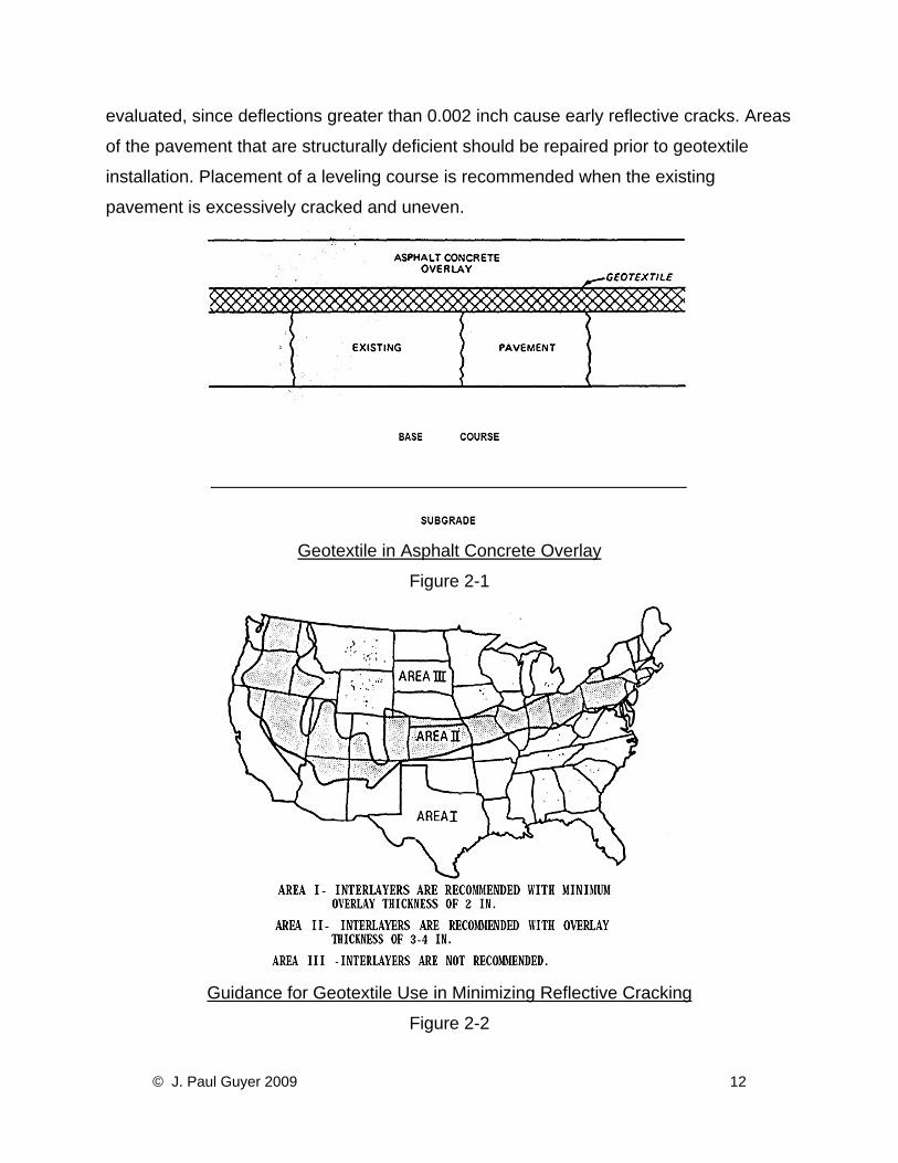
vertically. A typical pavement structure with a geotextile interlayer is shown in Figure 2-
1. Impregnation of the geotextile with a bitumen provides a degree of moisture
protection for the underlying layers whether or not reflective cracking occurs.
2.3 Reflective Crack Treatment for Pavements
2.3.1 General. Geotextiles can be used successfully in pavement rehabilitation
projects. Conditions that are compatible for the pavement applications of geotextiles are
AC pavements that may have transverse and longitudinal cracks but are relatively
smooth and structurally sound, and PCC pavements that have minimum slab
movement. The geographic location and climate of the project site have an important
part in determining whether or not geotextiles can be successfully used in pavement
rehabilitation. Geotextiles have been successful in reducing and retarding reflective
cracking in mild and dry climates when temperature and moisture changes are less
likely to contribute to movement of the underlying pavement; whereas, geotextiles in
cold climates have not been as successful. Figure 2-2 gives guidance in using
geotextiles to minimize reflective cracking on AC pavements. Geotextiles interlayers are
recommended for use in Areas I and II, but are not recommended for use in Area III.
Since geotextiles do not seem to increase the performance of thin overlays, minimum
overlay thicknesses for Areas I and II are given in Figure 2-2. Even when the climate
and thickness requirements are met, there has been no consistent increase in the time
it takes for reflective cracking to develop in the overlay indicating that other factors are
influencing performance. Other factors affecting performance of geotextile interlayers
are construction techniques involving pavement preparation, asphalt sealant
application, geotextile installation, and AC overlay as well as the condition of the
underlying pavement.
2.3.2 Surface Preparation. Prior to using geotextiles to minimize reflective cracks, the
existing pavement should be evaluated to determine pavement distress. The size of the
cracks and joints in the existing pavement should be determined. All cracks and joints
larger than ¼ inch in width should be sealed. Differential slab movement should be
© J. Paul Guyer 2009 11
evaluated, since deflections greater than 0.002 inch cause early reflective cracks. Areas
of the pavement that are structurally deficient should be repaired prior to geotextile
installation. Placement of a leveling course is recommended when the existing
pavement is excessively cracked and uneven.
Geotextile in Asphalt Concrete Overlay
Figure 2-1
Guidance for Geotextile Use in Minimizing Reflective Cracking
Figure 2-2
© J. Paul Guyer 2009 12
2.3.3 Geotextile Selection. 2.3.3.1 Geotextile interlayers are used in two different capacities-the full-width and
strip methods. The full-width method involves sealing cracks and joints and placing a
nonwoven material across the entire width of the existing pavement. The material
should have the properties shown in Table 2-1. Nonwoven materials provide more
flexibility and are recommended for reflective crack treatment of AC pavements.
2.3.3.2 The strip method is primarily used on Portland cement concrete (PCC)
pavements and involves preparing the existing cracks and joints, and placing a 12 to 24
inch wide geotextile and sufficient asphalt directly on the cracks and joints. The required
physical properties are shown in Table 2-1, however nonwoven geotextiles are not
normally used in the strip method. Membrane systems have been developed for strip
repairs.
2.3.4 Asphalt Sealant. The asphalt sealant is used to impregnate and seal the
geotextile and bond it to both the base pavement and overlay. The grade of asphalt
cement specified for hot-mix AC pavements in each geographic location is generally the
most acceptable material. Either anionic or cationic emulsion can also be used. Cutback
asphalts and emulsions which contain solvents should not be used.
2.3.5 AC Overlay. The thickness of the AC overlay should be determined from the
pavement structural requirements. For AC pavements, Area I shown in Figure 2-2
should have a minimum overlay thickness of 2 inches; whereas, Area II should have a
minimum overlay thickness of 3 inches. The minimum thickness of an AC overlay for
geotextile application on PCC pavements is 4 inches.
2.3.6 Spot Repairs. Rehabilitation of localized distressed areas and utility cuts can be
improved with the application of geotextiles. Isolated distressed areas that are
excessively cracked can be repaired with geotextiles prior to an AC overlay. Either a
full-width membrane strip application can be used depending on the size of the
distressed area. Localized distressed areas of existing AC pavement that are caused by
© J. Paul Guyer 2009 13
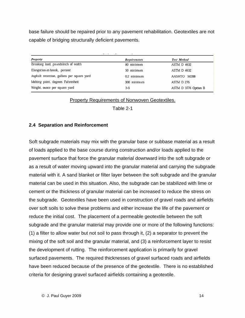
base failure should be repaired prior to any pavement rehabilitation. Geotextiles are not
capable of bridging structurally deficient pavements.
Property Requirements of Nonwoven Geotextiles.
Table 2-1
2.4 Separation and Reinforcement Soft subgrade materials may mix with the granular base or subbase material as a result
of loads applied to the base course during construction and/or loads applied to the
pavement surface that force the granular material downward into the soft subgrade or
as a result of water moving upward into the granular material and carrying the subgrade
material with it. A sand blanket or filter layer between the soft subgrade and the granular
material can be used in this situation. Also, the subgrade can be stabilized with lime or
cement or the thickness of granular material can be increased to reduce the stress on
the subgrade. Geotextiles have been used in construction of gravel roads and airfields
over soft soils to solve these problems and either increase the life of the pavement or
reduce the initial cost. The placement of a permeable geotextile between the soft
subgrade and the granular material may provide one or more of the following functions:
(1) a filter to allow water but not soil to pass through it, (2) a separator to prevent the
mixing of the soft soil and the granular material, and (3) a reinforcement layer to resist
the development of rutting. The reinforcement application is primarily for gravel
surfaced pavements. The required thicknesses of gravel surfaced roads and airfields
have been reduced because of the presence of the geotextile. There is no established
criteria for designing gravel surfaced airfields containing a geotextile.
© J. Paul Guyer 2009 14
2.5 Design for Separation When serving as a separator, the geotextile prevents fines from migrating into the base
course and/or prevents base course aggregate from penetrating into, the subgrade. The
soil retention properties of the geotextile are basically the same as those required for
drainage or filtration. Therefore, the retention and permeability criteria required for
drainage should be met. In addition, the geotextile should withstand the stresses
resulting from the load applied to the pavement. The nature of these stresses depend
on the condition of the subgrade, type of construction equipment, and the cover over the
subgrade. Since the geotextile serves to prevent aggregate from penetrating the
subgrade, it must meet puncture, burst, grab and tear strengths specified in the
following paragraphs.
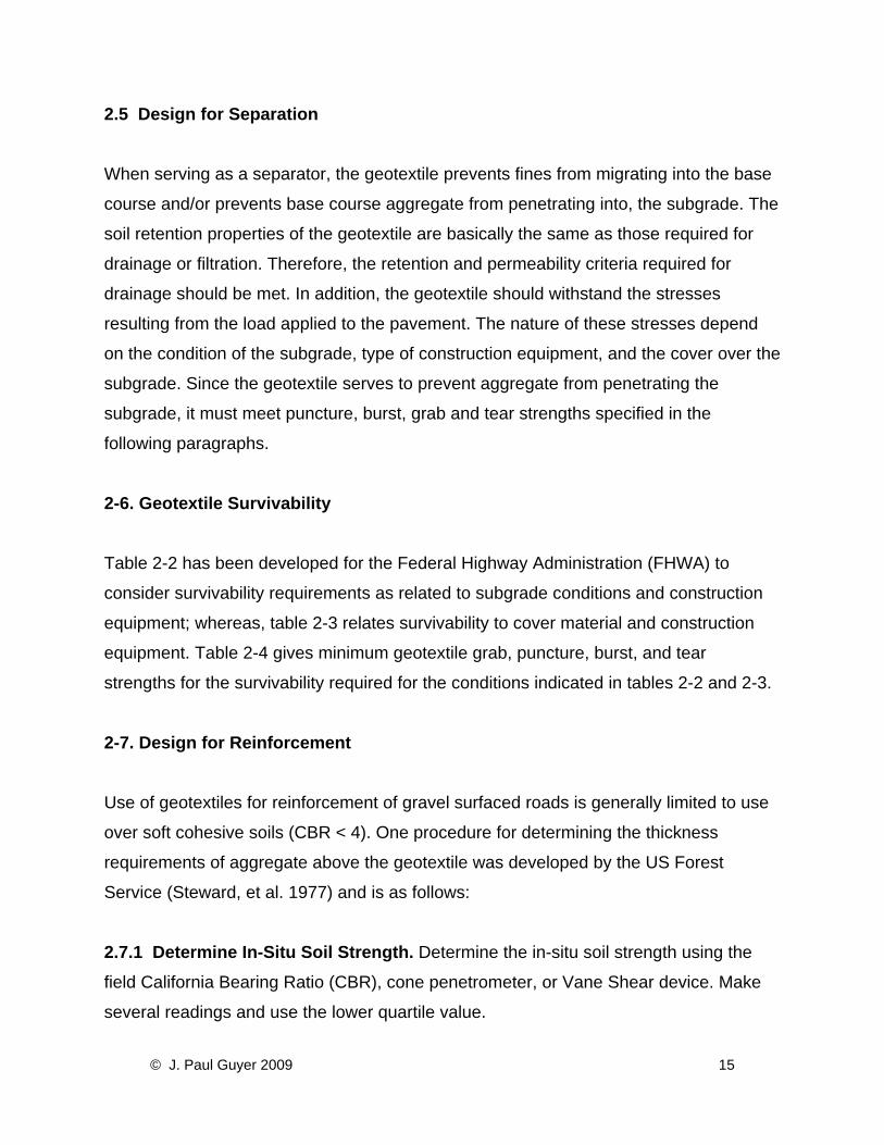
2-6. Geotextile Survivability Table 2-2 has been developed for the Federal Highway Administration (FHWA) to
consider survivability requirements as related to subgrade conditions and construction
equipment; whereas, table 2-3 relates survivability to cover material and construction
equipment. Table 2-4 gives minimum geotextile grab, puncture, burst, and tear
strengths for the survivability required for the conditions indicated in tables 2-2 and 2-3.
2-7. Design for Reinforcement
Use of geotextiles for reinforcement of gravel surfaced roads is generally limited to use
over soft cohesive soils (CBR < 4). One procedure for determining the thickness
requirements of aggregate above the geotextile was developed by the US Forest
Service (Steward, et al. 1977) and is as follows:
2.7.1 Determine In-Situ Soil Strength. Determine the in-situ soil strength using the
field California Bearing Ratio (CBR), cone penetrometer, or Vane Shear device. Make
several readings and use the lower quartile value.
© J. Paul Guyer 2009 15
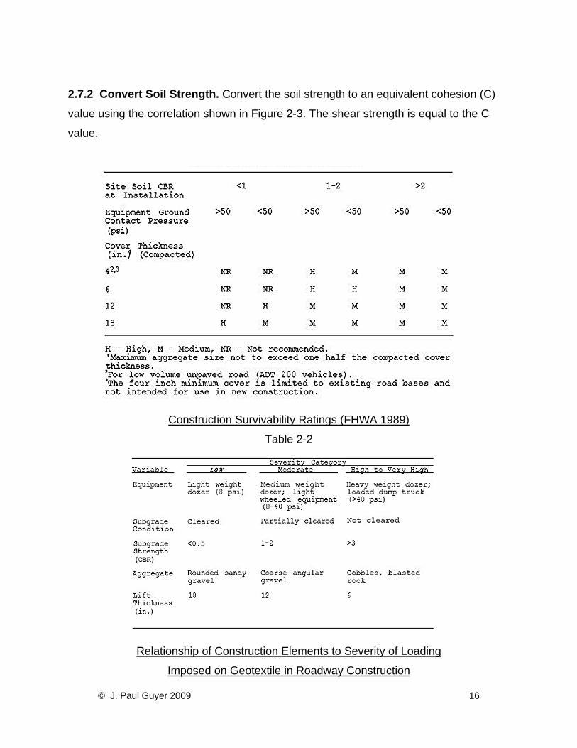
2.7.2 Convert Soil Strength. Convert the soil strength to an equivalent cohesion (C)
value using the correlation shown in Figure 2-3. The shear strength is equal to the C
value.
Construction Survivability Ratings (FHWA 1989)
Table 2-2
Relationship of Construction Elements to Severity of Loading
Imposed on Geotextile in Roadway Construction
© J. Paul Guyer 2009 16
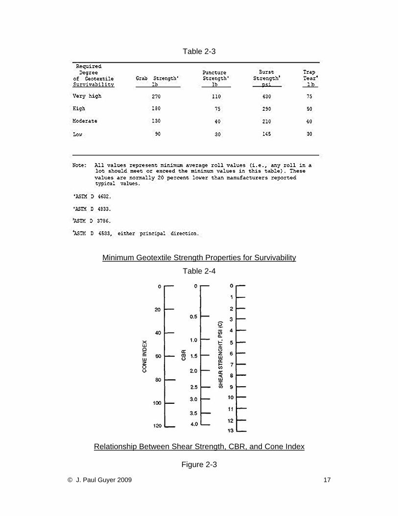
Table 2-3
Minimum Geotextile Strength Properties for Survivability
Table 2-4
Relationship Between Shear Strength, CBR, and Cone Index
Figure 2-3
© J. Paul Guyer 2009 17
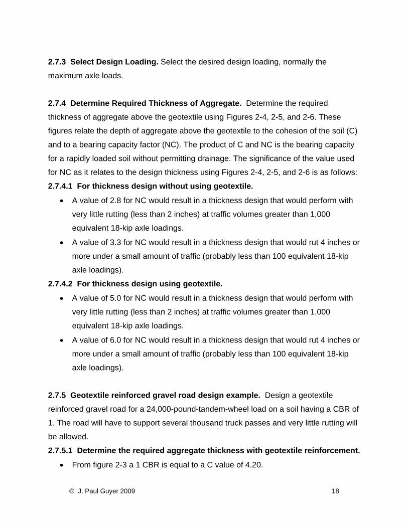
2.7.3 Select Design Loading. Select the desired design loading, normally the
maximum axle loads.
2.7.4 Determine Required Thickness of Aggregate. Determine the required
thickness of aggregate above the geotextile using Figures 2-4, 2-5, and 2-6. These
figures relate the depth of aggregate above the geotextile to the cohesion of the soil (C)
and to a bearing capacity factor (NC). The product of C and NC is the bearing capacity
for a rapidly loaded soil without permitting drainage. The significance of the value used
for NC as it relates to the design thickness using Figures 2-4, 2-5, and 2-6 is as follows:
2.7.4.1 For thickness design without using geotextile.
• A value of 2.8 for NC would result in a thickness design that would perform with
very little rutting (less than 2 inches) at traffic volumes greater than 1,000
equivalent 18-kip axle loadings.
• A value of 3.3 for NC would result in a thickness design that would rut 4 inches or
more under a small amount of traffic (probably less than 100 equivalent 18-kip
axle loadings).
2.7.4.2 For thickness design using geotextile.
• A value of 5.0 for NC would result in a thickness design that would perform with
very little rutting (less than 2 inches) at traffic volumes greater than 1,000
equivalent 18-kip axle loadings.
• A value of 6.0 for NC would result in a thickness design that would rut 4 inches or
more under a small amount of traffic (probably less than 100 equivalent 18-kip
axle loadings).
2.7.5 Geotextile reinforced gravel road design example. Design a geotextile
reinforced gravel road for a 24,000-pound-tandem-wheel load on a soil having a CBR of
1. The road will have to support several thousand truck passes and very little rutting will be allowed. 2.7.5.1 Determine the required aggregate thickness with geotextile reinforcement.
• From figure 2-3 a 1 CBR is equal to a C value of 4.20.
© J. Paul Guyer 2009 18
• Choose a value of 5 for NC since very little rutting will be allowed.
• Calculate CNC as: CNC = 4.20(5) = 21.
• Enter figure 2-6 with CNC of 21 to obtain a value of 14 inches as the required
aggregate thickness above the geotextile.
• Select geotextile requirements based on
• survivability requirements in tables 2-2 and 2-3.
2.7.5.2 Determine the required aggregate thickness when a geotextile is not used.
• Use a value of 2.8 for NC since a geotextile is not used and only a small amount
of rutting will be allowed.
• Calculate CNC as: CNC = 4.20(2.8) = 11.8.
• Enter figure 2-6 with CNC of 11.8 to obtain a value of 22 inches as the required
aggregate thickness above the subgrade without the geotextile.
2.7.5.3 Compare cost and benefits of the alternatives. Even with nearby economical
gravel sources, the use of a geotextile usually is the more economical alternative for
constructing low volume roads and airfields over soft cohesive soils. Additionally, it results in a faster time to completion once the geotextiles are delivered on site.
© J. Paul Guyer 2009 19
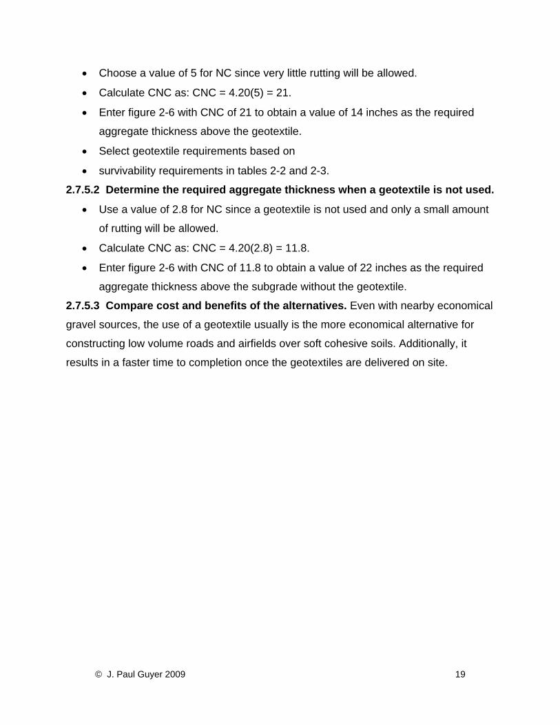
Thickness Design Curve for Single- Wheel Load on Gravel-Surfaced Roads
Figure 2-4
© J. Paul Guyer 2009 20
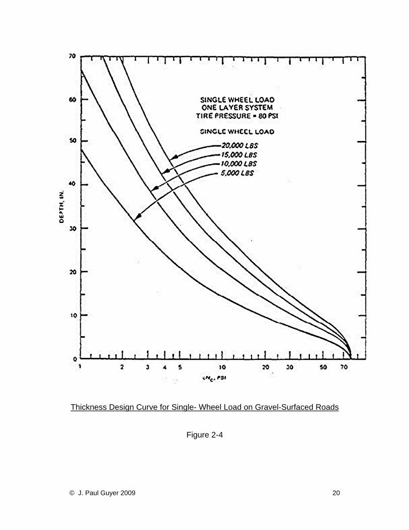
Thickness Design Curve for Dual- Wheel Load on Gravel-Surfaced Roads
Table 2-5
© J. Paul Guyer 2009 21
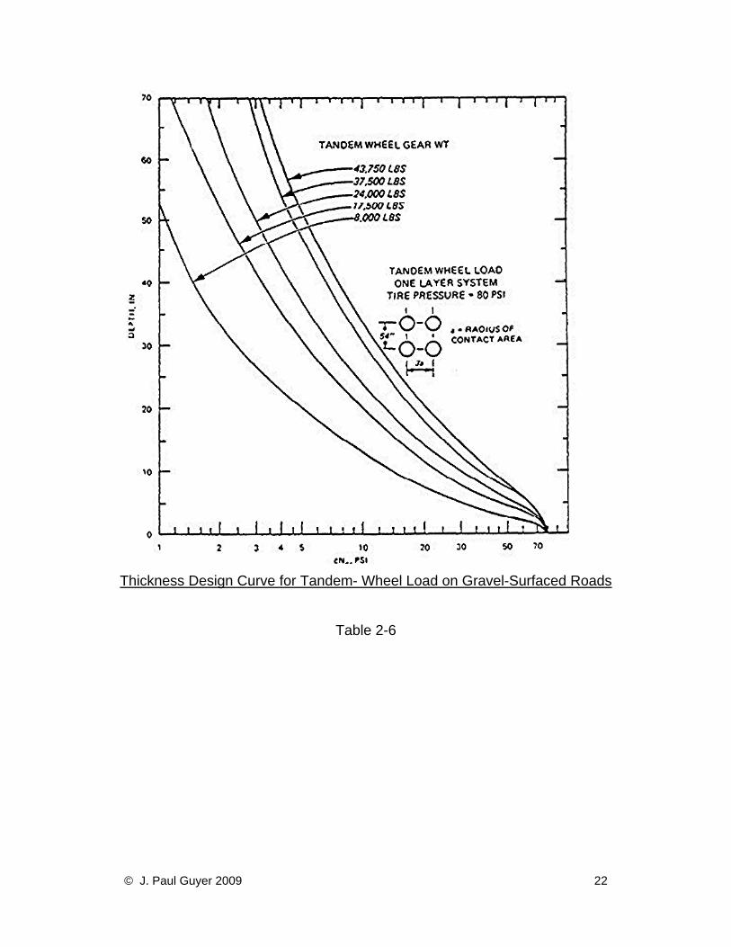
Thickness Design Curve for Tandem- Wheel Load on Gravel-Surfaced Roads
Table 2-6
© J. Paul Guyer 2009 22
3. DRAINAGE APPLICATIONS 3.1 Water Control Control of water is critical to the performance of buildings, pavements, embankments,
retaining walls, and other structures. Drains are used to relieve hydrostatic pressure
against underground and retaining walls, slabs, and underground tanks and to prevent
loss of soil strength and stability in slopes, embankments, and beneath pavements. A
properly functioning drain must retain the surrounding soil while readily accepting water
from the soil and removing it from the area. These general requirements apply to
granular and geotextile filters. While granular drains have a long performance history,
geotextile use in drains is relatively recent and performance data are limited to
approximately 25 years. Where not exposed to sunlight or abrasive contact with rocks
moving in response to moving surface loads or wave action, long-term performance of
properly selected geotextiles has been good. Since long-term experience is limited,
geotextiles should not be used as a substitute for granular filters within or on the
upstream face of earth dams or within any inaccessible portion of the dam
embankment. Geotextiles have been used in toe drains of embankments where they
are easily accessible if maintenance is required and where malfunction can be detected.
Caution is advised in using geotextiles to wrap permanent piezometers and relief wells
where they form part of the safety system of a water retaining structure. Geotextiles
have been used to prevent infiltration of fine-grained materials into piezometer screens
but long-term performance has not been measured.
3.2 Granular Drain Performance To assure proper performance in granular drains, the designer requires drain materials
to meet grain-size requirements based on grain size of the surrounding soil. The two
principal granular filter criteria, piping and permeability have been developed empirically
through project experience and laboratory testing.
© J. Paul Guyer 2009 23
3.3 Geotextile Characteristics Influencing Filter Functions
The primary geotextile characteristics influencing filter functions are opening size (as
related to soil retention), flow capacity, and clogging potential. These properties are
indirectly measured by the apparent opening size (AOS) (ASTM D 4751), permittivity
(ASTM D 4491), and gradient ratio test (ASTM D 5101). The geotextile must also have
the strength and durability to survive construction and long-term conditions for the
design life of the drain. Additionally, construction methods have a critical influence on
geotextile drain performance.
3.4 Piping Resistance
3.4.1 Basic Criteria. Piping resistance is the ability of a geotextile to retain solid
particles and is related to the sizes and complexity of the openings or pores in the
geotextile. For both woven and nonwoven geotextiles, the critical parameter is the AOS.
Table 3-1 gives the relation of AOS to the gradation of the soil passing the number 200
sieve for use in selecting geotextiles.
3.4.2 Percent Open Area Determination Procedure for Woven Geotextiles.
3.4.2.1 Installation of geotextile. A small section of the geotextile to be tested should
be installed in a standard 2 by 2 inch slide cover, so that it can be put into a slide
projector and projected onto a screen. Any method to hold the geotextile section and
maintain it perpendicular to the projected light can be used.
3.4.2.2 Slide projector. The slide projector should be placed level to eliminate any
distortion of the geotextile openings. After placing the slide in the projector and focusing
on a sheet of paper approximately 8 to 10 feet away, the opening outlines can
be traced.
© J. Paul Guyer 2009 24
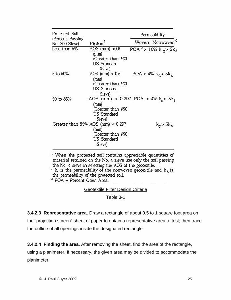
Geotextile Filter Design Criteria
Table 3-1
3.4.2.3 Representative area. Draw a rectangle of about 0.5 to 1 square foot area on
the “projection screen” sheet of paper to obtain a representative area to test; then trace
the outline of all openings inside the designated rectangle.
3.4.2.4 Finding the area. After removing the sheet, find the area of the rectangle,
using a planimeter. If necessary, the given area may be divided to accommodate the
planimeter.
© J. Paul Guyer 2009 25
3.4.2.5 Total area of openings. Find the total area of openings inside rectangle,
measuring the area of each with a planimeter.
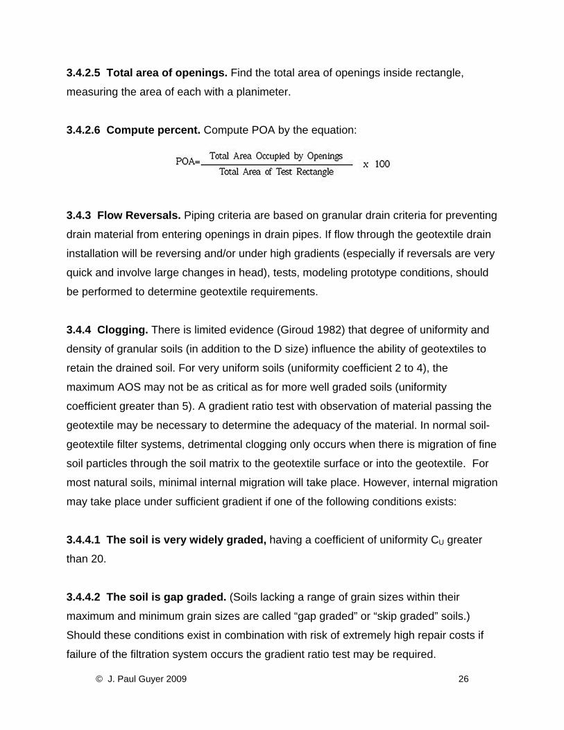
3.4.2.6 Compute percent. Compute POA by the equation:
3.4.3 Flow Reversals. Piping criteria are based on granular drain criteria for preventing
drain material from entering openings in drain pipes. If flow through the geotextile drain
installation will be reversing and/or under high gradients (especially if reversals are very
quick and involve large changes in head), tests, modeling prototype conditions, should
be performed to determine geotextile requirements.
3.4.4 Clogging. There is limited evidence (Giroud 1982) that degree of uniformity and
density of granular soils (in addition to the D size) influence the ability of geotextiles to
retain the drained soil. For very uniform soils (uniformity coefficient 2 to 4), the
maximum AOS may not be as critical as for more well graded soils (uniformity
coefficient greater than 5). A gradient ratio test with observation of material passing the
geotextile may be necessary to determine the adequacy of the material. In normal soil-
geotextile filter systems, detrimental clogging only occurs when there is migration of fine
soil particles through the soil matrix to the geotextile surface or into the geotextile. For
most natural soils, minimal internal migration will take place. However, internal migration
may take place under sufficient gradient if one of the following conditions exists:
3.4.4.1 The soil is very widely graded, having a coefficient of uniformity CU greater
than 20.
3.4.4.2 The soil is gap graded. (Soils lacking a range of grain sizes within their
maximum and minimum grain sizes are called “gap graded” or “skip graded” soils.)
Should these conditions exist in combination with risk of extremely high repair costs if
failure of the filtration system occurs the gradient ratio test may be required.
© J. Paul Guyer 2009 26
3.4.5 Clogging Resistance. Clogging is the reduction in permeability or permittivity of
a geotextile due to blocking of the pores by either soil particles or biological or chemical
deposits. Some clogging takes place with all geotextiles in contact with soil. Therefore,
permeability test results can only be used as a guide for geotextile suitability. For woven
geotextiles, if the POA is sufficiently large, the geotextiles will be resistant to clogging.
The POA has proved to be a useful measure of clogging resistance for woven textiles
but is limited to woven geotextiles having distinct, easily measured openings. For
geotextiles which cannot be evaluated by POA, soil- geotextile permeameters have
been developed for measuring soil-geotextile permeability and clogging. As a measure
of the degree to which the presence of geotextile affects the permeability of the soil-
geotextile system, the gradient ratio test can be used (ASTM D 5101).
The gradient ratio is defined as the ratio of the hydraulic gradient across the geotextile
and the 1 inch of soil immediately above the geotextile to the hydraulic gradient
between 1 and 3 inches above the geotextile.
3.5 Permeability
3.5.1 Transverse Permeability. After installation, geotextiles used in filtration and
drainage applications must have a flow capacity adequate to prevent significant the soil
being drained. This flow capacity must be maintained for the range of flow conditions for
that particular installation. For soils, the indicator of flow capacity is the coefficient of
permeability as expressed in Darcy's Law. The proper application of Darcy’s Law
requires that geotextile thickness be considered. Since the ease of flow through a
geotextile regardless of its thickness is the property of primary interest, Darcy’s Law can
be modified to define the term permittivity, Y, with units of sec., as follows:
© J. Paul Guyer 2009 27
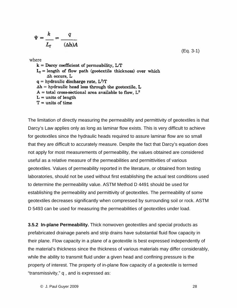
(Eq. 3-1)
The limitation of directly measuring the permeability and permittivity of geotextiles is that
Darcy’s Law applies only as long as laminar flow exists. This is very difficult to achieve
for geotextiles since the hydraulic heads required to assure laminar flow are so small
that they are difficult to accurately measure. Despite the fact that Darcy’s equation does
not apply for most measurements of permeability, the values obtained are considered
useful as a relative measure of the permeabilities and permittivities of various
geotextiles. Values of permeability reported in the literature, or obtained from testing
laboratories, should not be used without first establishing the actual test conditions used
to determine the permeability value. ASTM Method D 4491 should be used for
establishing the permeability and permittivity of geotextiles. The permeability of some
geotextiles decreases significantly when compressed by surrounding soil or rock. ASTM
D 5493 can be used for measuring the permeabilities of geotextiles under load.
3.5.2 In-plane Permeability. Thick nonwoven geotextiles and special products as
prefabricated drainage panels and strip drains have substantial fluid flow capacity in
their plane. Flow capacity in a plane of a geotextile is best expressed independently of
the material’s thickness since the thickness of various materials may differ considerably,
while the ability to transmit fluid under a given head and confining pressure is the
property of interest. The property of in-plane flow capacity of a geotextile is termed
“transmissivity,” q , and is expressed as:
© J. Paul Guyer 2009 28
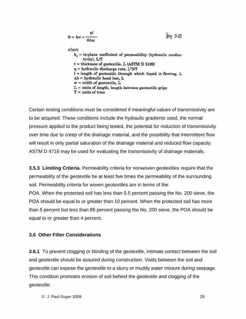
Certain testing conditions must be considered if meaningful values of transmissivity are
to be acquired. These conditions include the hydraulic gradients used, the normal
pressure applied to the product being tested, the potential for reduction of transmissivity
over time due to creep of the drainage material, and the possibility that intermittent flow
will result in only partial saturation of the drainage material and reduced flow capacity.
ASTM D 4716 may be used for evaluating the transmissivity of drainage materials.
3.5.3 Limiting Criteria. Permeability criteria for nonwoven geotextiles require that the
permeability of the geotextile be at least five times the permeability of the surrounding
soil. Permeability criteria for woven geotextiles are in terms of the
POA. When the protected soil has less than 0.5 percent passing the No. 200 sieve, the
POA should be equal to or greater than 10 percent. When the protected soil has more
than 5 percent but less than 85 percent passing the No. 200 sieve, the POA should be
equal to or greater than 4 percent.
3.6 Other Filter Considerations 3.6.1 To prevent clogging or blinding of the geotextile, intimate contact between the soil
and geotextile should be assured during construction. Voids between the soil and
geotextile can expose the geotextile to a slurry or muddy water mixture during seepage.
This condition promotes erosion of soil behind the geotextile and clogging of the
geotextile.
© J. Paul Guyer 2009 29
3.6.2 Very fine-grained non-cohesive soils, such as rock flour, present a special
problem, and design of drain installations in this type of soil should be based on tests
with expected hydraulic conditions using the soil and candidate geotextiles.
3.6.3 As a general rule slit-film geotextiles are unacceptable for drainage applications.
They may meet AOS criteria but generally have a very low POA or permeability. The
wide filament in many slit films is prone to move relative to the cross filaments during
handling and thus change AOS and POA.
3.6.4 The designer must consider that in certain areas an ochre formation may occur
on the geotextile. Ochre is an iron deposit usually a red or tan gelatinous mass
associated with bacterial slimes. It can, under certain conditions, form on and in
subsurface drains. The designer may be able to determine the potential for ochre
formation by reviewing local experience with highway, agricultural, embankment, or
other drains with local or state agencies. If there is reasonable expectation for ochre
formation, use of geotextiles is discouraged since geotextiles may be more prone to
clog. Once ochre clogging occurs, removal from geotextiles is generally very difficult to
impossible, since chemicals or acids used for ochre removal can damage geotextiles,
and high pressure jetting through the perforated pipe is relatively ineffective on clogged
geotextiles.
3.7 Strength Requirements Unless geotextiles used in drainage applications have secondary functions (separation,
reinforcement, etc.) requiring high strength, the requirements shown in Table 3-2 will
provide adequate strength.
© J. Paul Guyer 2009 30
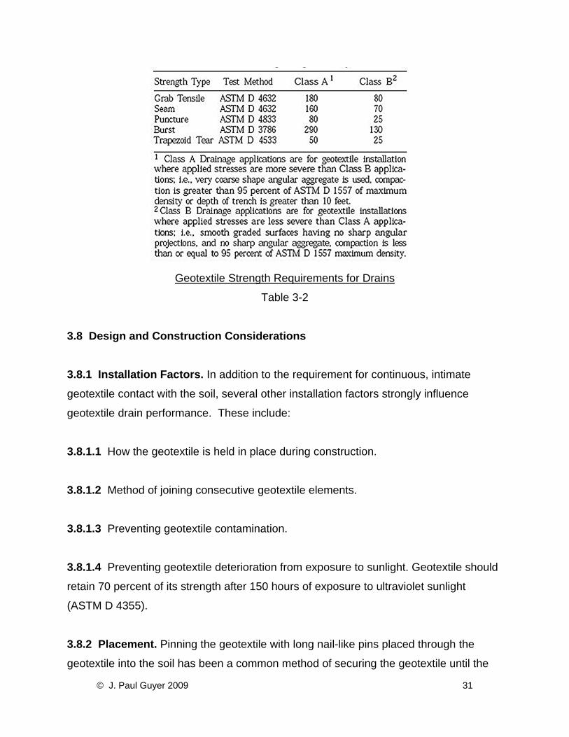
Geotextile Strength Requirements for Drains
Table 3-2
3.8 Design and Construction Considerations 3.8.1 Installation Factors. In addition to the requirement for continuous, intimate
geotextile contact with the soil, several other installation factors strongly influence
geotextile drain performance. These include:
3.8.1.1 How the geotextile is held in place during construction.
3.8.1.2 Method of joining consecutive geotextile elements.
3.8.1.3 Preventing geotextile contamination.
3.8.1.4 Preventing geotextile deterioration from exposure to sunlight. Geotextile should
retain 70 percent of its strength after 150 hours of exposure to ultraviolet sunlight
(ASTM D 4355).
3.8.2 Placement. Pinning the geotextile with long nail-like pins placed through the
geotextile into the soil has been a common method of securing the geotextile until the
© J. Paul Guyer 2009 31
other components of the drain have been placed; however, in some applications, this
method has created problems. Placement of aggregate on the pinned geotextile
normally puts the geotextile into tension which increases potential for puncture and
reduces contact of the geotextile with soil, particularly when placing the geotextile
against vertical and/or irregular soil surfaces. It is much better to keep the geotextile
loose but relatively unwrinkled during aggregate placement. This can be done by using
small amounts of aggregate to hold the geotextile in place or using loose pinning and
re-pinning as necessary to keep the geotextile loose. This method of placement will
typically require 10 to 15 percent more geotextile than predicted by measurement of the
drain’s planer surfaces.
3.8.3 Joints.
3.8.3.1 Secure lapping or joining of consecutive pieces of geotextile prevents
movement of soil into the drain. A variety of methods such as sewing, heat bonding, and
overlapping are acceptable joints. Normally, where the geotextile joint will not be
stressed after installation, a minimum 12-inch overlap is required with the overlapping
inspected to ensure complete geotextile-to-geotextile contact. When movement of the
geotextile sections is possible after placement, appropriate overlap distances or more
secure joining methods should be specified. Field joints are much more difficult to
control than those made at the factory or fabrication site and every effort should be
made to minimize field joining.
3.8.3.2 Strength requirements for seams may vary from just enough to hold the
geotextile sections together for installation to that required for the geotextile. Additional
guidance for seams is contained in AASHTO M 288. Seam strength is determined using
ASTM 4632.
3.8.4 Trench Drains.
© J. Paul Guyer 2009 32
3.8.4.1 Variations of the basic trench drain are the most common geotextile drain
application. Typically, the geotextile lines the trench allowing use of a very permeable
backfill which quickly removes water entering the drain. Trench drains intercept surface
infiltration in pavements and seepage in slopes and embankments as well as lowering
ground-water levels beneath pavements and other structures. The normal construction
sequence is shown in Figure 3-l. In addition to techniques shown in Figure 3-1, if high
compactive efforts are required (e.g., 95 percent of ASTM D 1557 maximum density),
the puncture strength requirements should be doubled. Granular backfill does not have
to meet piping criteria but should be highly permeable, large enough to prevent
movement into the pipe, and meet durability and structural requirements of the project.
This allows the designer to be much less stringent on backfill requirements than would
be necessary for a totally granular trench drain. Some compaction of the backfill should
always be applied.
3.8.4.2 Wrapping of the perforated drain pipe with a geotextile when finer grained filter
backfill is used is a less common practice. Normally not used in engineering
applications, this method is less efficient than lining the trench with a geotextile because
the reduced area of high permeability material concentrates flow and lowersa drain
efficiency. Wrapping of the pipe may be useful when finer grained filter materials are
best suited because of availability and/or grain size requirements. In this case, the
geotextile functions as a cover for the pipe perforations preventing backfill infiltration. If
the geotextile can be separated a small distance from the pipe surface, the flow through
the geotextile into the pipe openings will be much more efficient. Use of plastic
corrugated, perforated pipe with openings in the depressed portion of the corrugation is
an easy way of doing this.
© J. Paul Guyer 2009 33
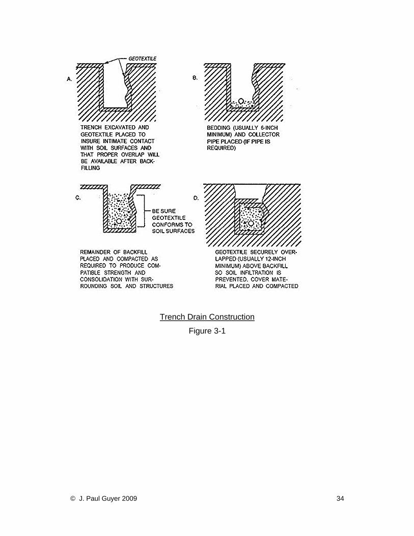
Trench Drain Construction
Figure 3-1
© J. Paul Guyer 2009 34