Embed Size (px)
DESCRIPTION
Introduction to FPGA Development. Justin Thiel Two Sigma Investments. Mapping Operations to HW. always @( posedge clk ) begin r_x
Citation preview
Introduction to FPGA Development
Justin ThielTwo Sigma Investments
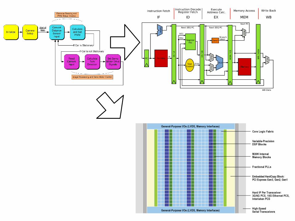
always @(posedge clk) begin r_x <= x;
if (x) r_y <= r_x;end
x r_x r_y
clk
FlipFlop
FlipFlop
Mapping Operations to HW
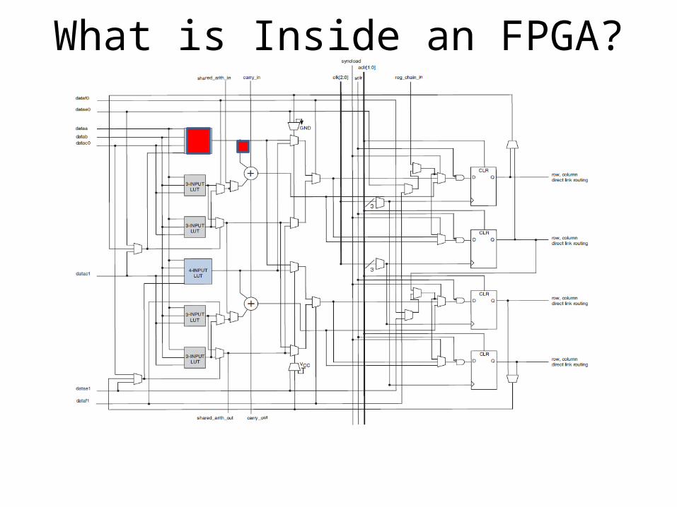
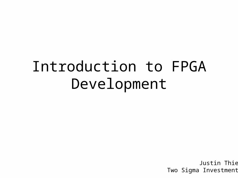
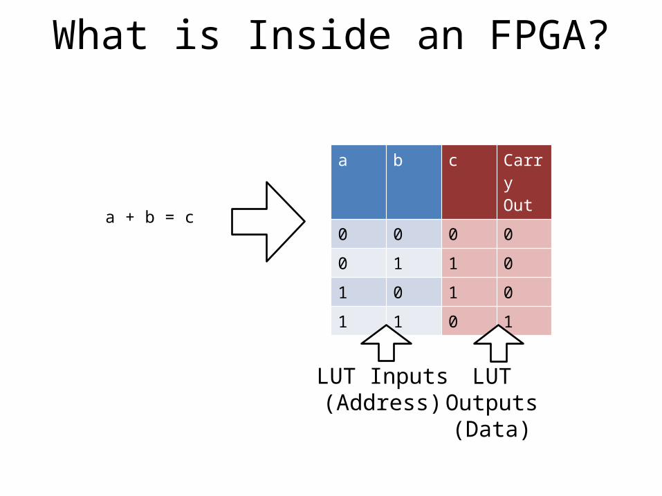
What is Inside an FPGA?
What is Inside an FPGA?
a b c CarryOut
0 0 0 0
0 1 1 0
1 0 1 0
1 1 0 1
a + b = c
LUT Inputs (Address)
LUT Outputs (Data)
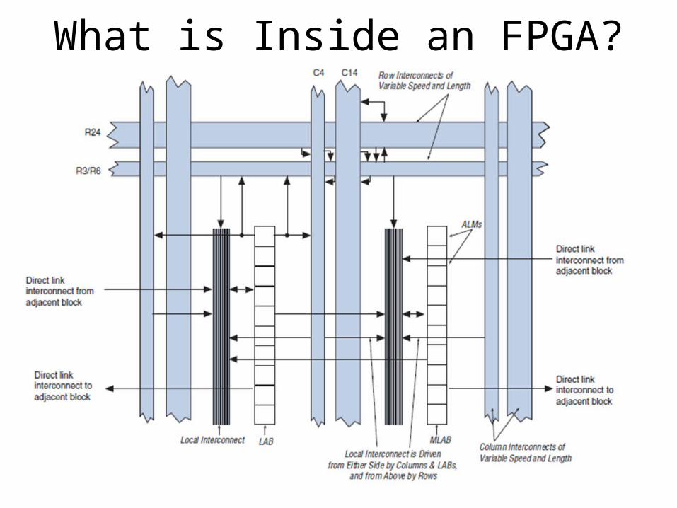
What is Inside an FPGA?
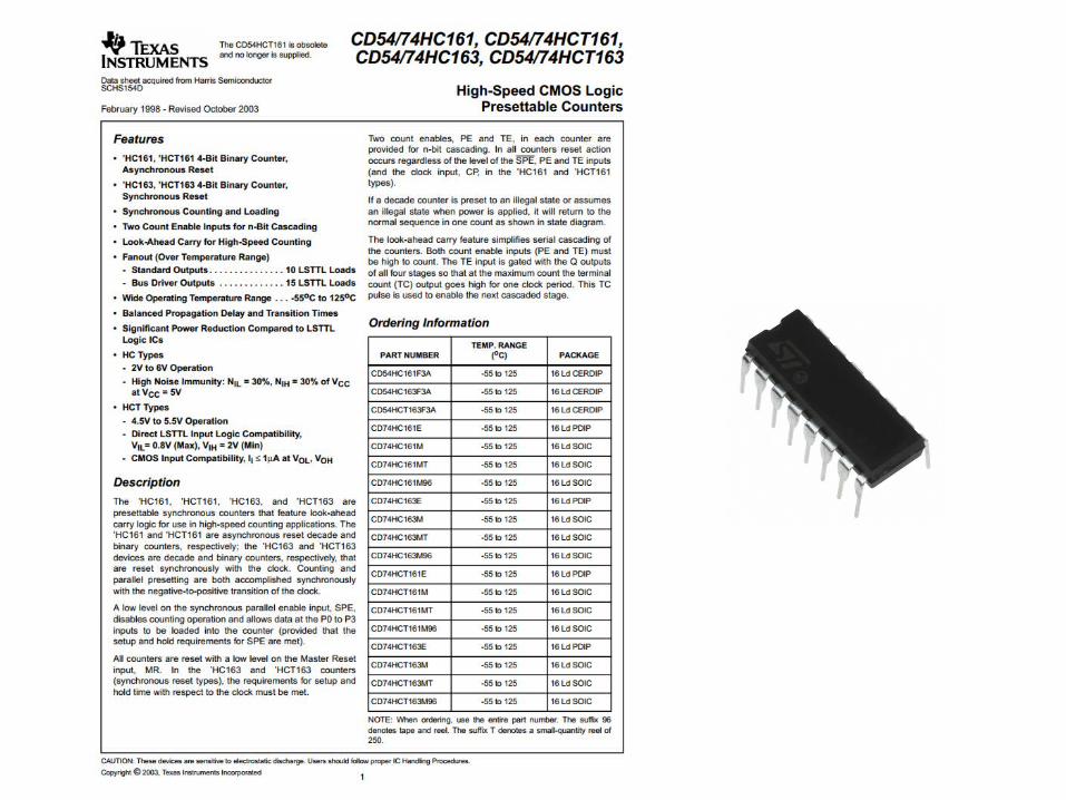
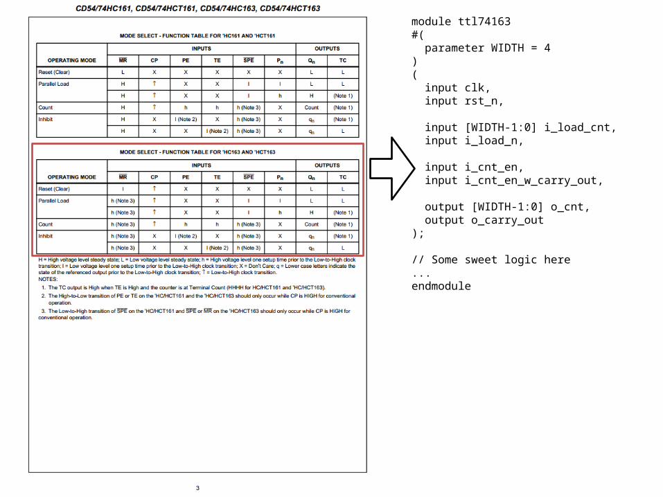
module ttl74163#( parameter WIDTH = 4)( input clk, input rst_n,
input [WIDTH-1:0] i_load_cnt, input i_load_n,
input i_cnt_en, input i_cnt_en_w_carry_out,
output [WIDTH-1:0] o_cnt, output o_carry_out);
// Some sweet logic here...endmodule
Exercise 174163 Binary Counter Simulation

Verilog Primer
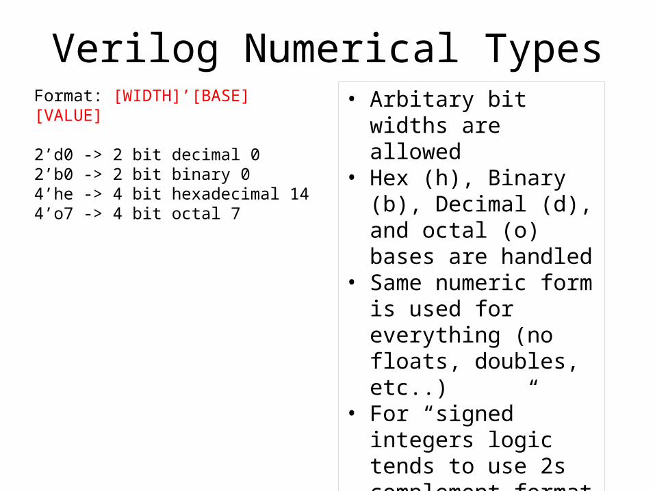
Verilog Numerical TypesFormat: [WIDTH]’[BASE][VALUE]
2’d0 -> 2 bit decimal 02’b0 -> 2 bit binary 04’he -> 4 bit hexadecimal 144’o7 -> 4 bit octal 7
• Arbitary bit widths are allowed
• Hex (h), Binary (b), Decimal (d), and octal (o) bases are handled
• Same numeric form is used for everything (no floats, doubles, etc..)
• For “signed” integers logic tends to use 2s complement format
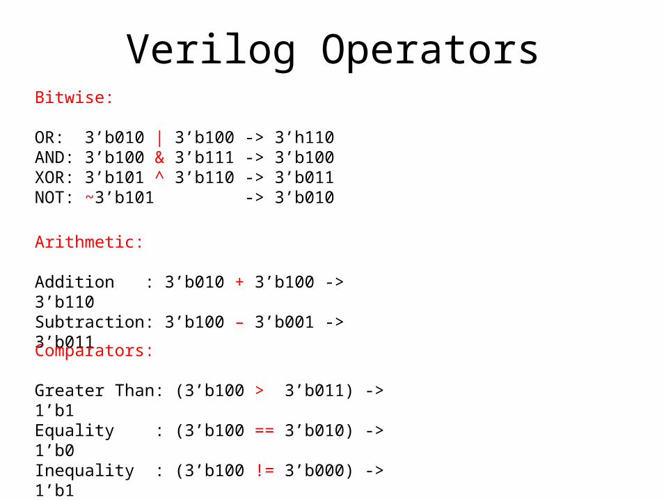
Verilog OperatorsBitwise:
OR: 3’b010 | 3’b100 -> 3’h110AND: 3’b100 & 3’b111 -> 3’b100XOR: 3’b101 ^ 3’b110 -> 3’b011NOT: ~3’b101 -> 3’b010
Arithmetic:
Addition : 3’b010 + 3’b100 -> 3’b110Subtraction: 3’b100 – 3’b001 -> 3’b011Comparators:
Greater Than: (3’b100 > 3’b011) -> 1’b1Equality : (3’b100 == 3’b010) -> 1’b0Inequality : (3’b100 != 3’b000) -> 1’b1
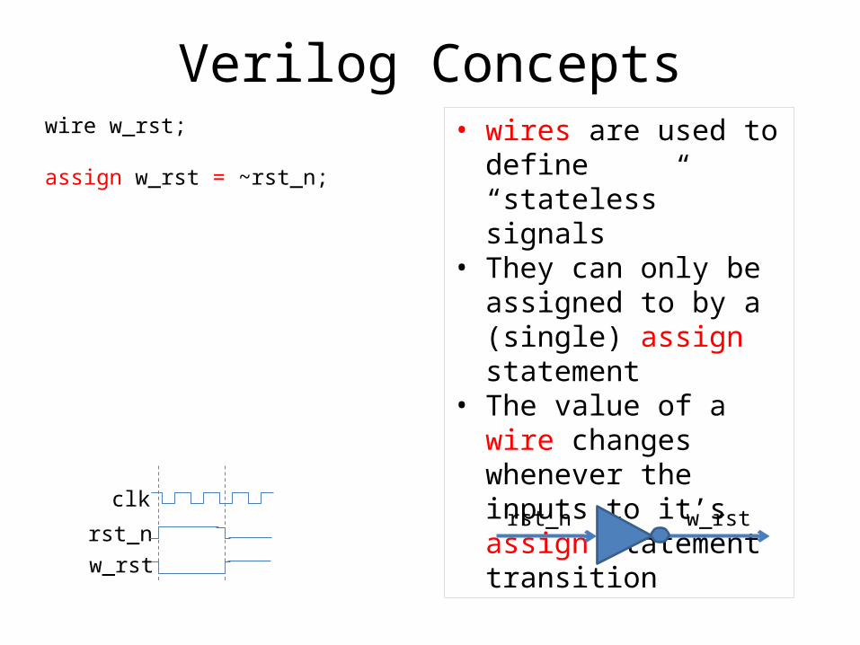
Verilog Conceptswire w_rst;
assign w_rst = ~rst_n;
• wires are used to define “stateless” signals
• They can only be assigned to by a (single) assign statement
• The value of a wire changes whenever the inputs to it’s assign statement transition
clk
rst_nw_rst
w_rstrst_n
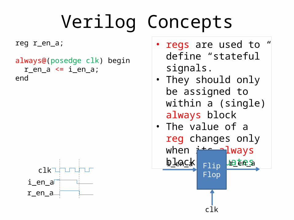
Verilog Conceptsreg r_en_a;
always@(posedge clk) begin r_en_a <= i_en_a;end
• regs are used to define “stateful” signals.
• They should only be assigned to within a (single) always block
• The value of a reg changes only when its always block evaluates
FlipFlop
r_en_ai_en_a
clk
clk
i_en_ar_en_a
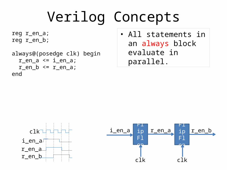
Verilog Conceptsreg r_en_a;reg r_en_b;
always@(posedge clk) begin r_en_a <= i_en_a; r_en_b <= r_en_a;end
• All statements in an always block evaluate in parallel.
FlipFlop
r_en_ai_en_a
clk
clk
i_en_ar_en_ar_en_b
FlipFlop
r_en_b
clk
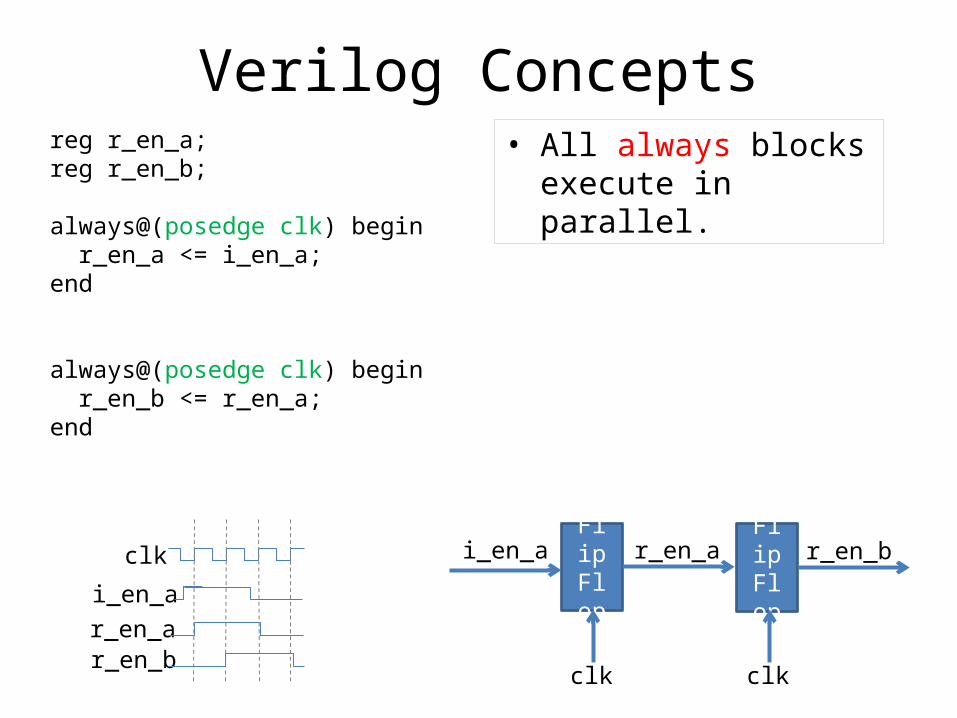
Verilog Conceptsreg r_en_a;reg r_en_b;
always@(posedge clk) begin r_en_a <= i_en_a;end
always@(posedge clk) begin r_en_b <= r_en_a;end
• All always blocks execute in parallel.
FlipFlop
r_en_ai_en_a
clk
clk
i_en_ar_en_ar_en_b
FlipFlop
r_en_b
clk
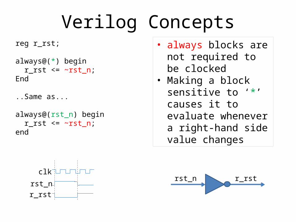
Verilog Conceptsreg r_rst;
always@(*) begin r_rst <= ~rst_n;End
..Same as...
always@(rst_n) begin r_rst <= ~rst_n;end
• always blocks are not required to be clocked
• Making a block sensitive to ‘*’ causes it to evaluate whenever a right-hand side value changes
clk
rst_nr_rst
r_rstrst_n
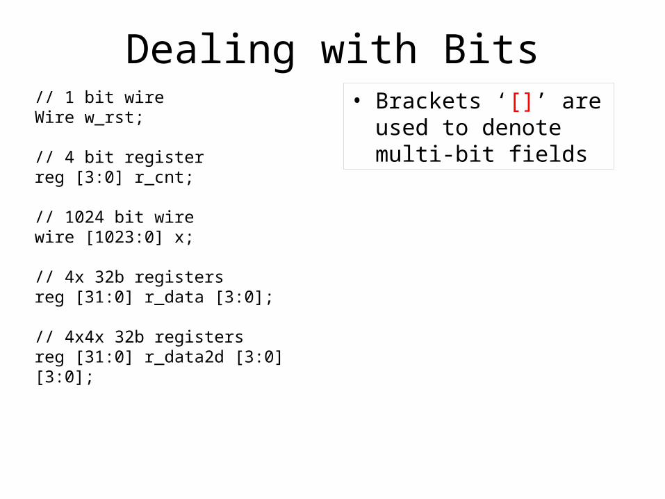
Dealing with Bits// 1 bit wireWire w_rst;
// 4 bit registerreg [3:0] r_cnt;
// 1024 bit wirewire [1023:0] x;
// 4x 32b registers reg [31:0] r_data [3:0];
// 4x4x 32b registersreg [31:0] r_data2d [3:0][3:0];
• Brackets ‘[]’ are used to denote multi-bit fields
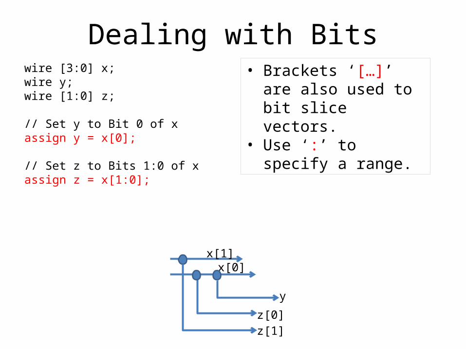
Dealing with Bitswire [3:0] x;wire y;wire [1:0] z;
// Set y to Bit 0 of xassign y = x[0];
// Set z to Bits 1:0 of xassign z = x[1:0];
• Brackets ‘[…]’ are also used to bit slice vectors.
• Use ‘:’ to specify a range.
x[1]x[0]
y
z[1]z[0]
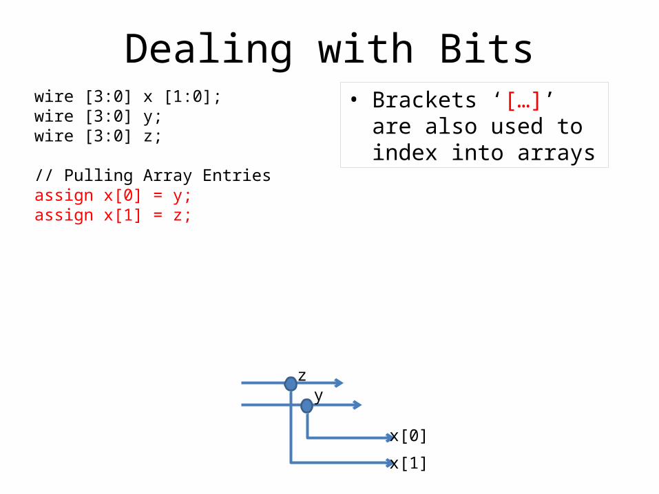
Dealing with Bitswire [3:0] x [1:0];wire [3:0] y;wire [3:0] z;
// Pulling Array Entriesassign x[0] = y;assign x[1] = z;
• Brackets ‘[…]’ are also used to index into arrays
zy
x[0]
x[1]
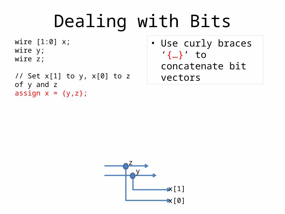
Dealing with Bitswire [1:0] x;wire y;wire z;
// Set x[1] to y, x[0] to z of y and zassign x = {y,z};
• Use curly braces ‘{…}’ to concatenate bit vectors
zy
x[1]
x[0]
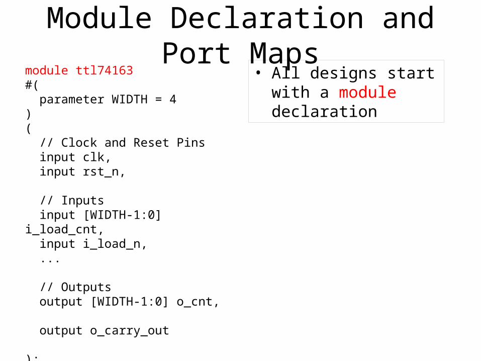
Module Declaration and Port Mapsmodule ttl74163#( parameter WIDTH = 4)( // Clock and Reset Pins input clk, input rst_n,
// Inputs input [WIDTH-1:0] i_load_cnt, input i_load_n, ... // Outputs output [WIDTH-1:0] o_cnt, output o_carry_out );
• All designs start with a module declaration
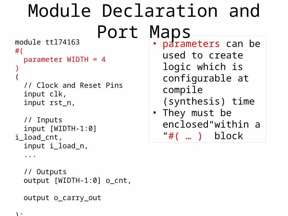
Module Declaration and Port Mapsmodule ttl74163#( parameter WIDTH = 4)( // Clock and Reset Pins input clk, input rst_n,
// Inputs input [WIDTH-1:0] i_load_cnt, input i_load_n, ... // Outputs output [WIDTH-1:0] o_cnt, output o_carry_out );
• parameters can be used to create logic which is configurable at compile (synthesis) time
• They must be enclosed within a “#( … )” block
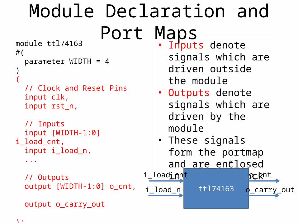
Module Declaration and Port Mapsmodule ttl74163#( parameter WIDTH = 4)( // Clock and Reset Pins input clk, input rst_n,
// Inputs input [WIDTH-1:0] i_load_cnt, input i_load_n, ...
// Outputs output [WIDTH-1:0] o_cnt, output o_carry_out );
• Inputs denote signals which are driven outside the module
• Outputs denote signals which are driven by the module
• These signals form the portmap and are enclosed in a “(…)” block
ttl74163
i_load_cnt
i_load_n
o_cnt
o_carry_out
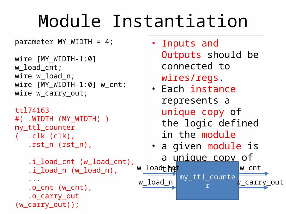
Module Instantiationparameter MY_WIDTH = 4;
wire [MY_WIDTH-1:0] w_load_cnt;wire w_load_n;wire [MY_WIDTH-1:0] w_cnt;wire w_carry_out;
ttl74163#( .WIDTH (MY_WIDTH) )my_ttl_counter( .clk (clk), .rst_n (rst_n),
.i_load_cnt (w_load_cnt), .i_load_n (w_load_n), ... .o_cnt (w_cnt), .o_carry_out (w_carry_out));
• Inputs and Outputs should be connected to wires/regs.
• Each instance represents a unique copy of the logic defined in the module
• a given module is a unique copy of the logic
my_ttl_counter
w_load_cnt
w_load_n
w_cnt
w_carry_out
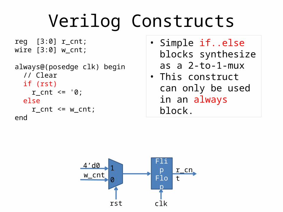
Verilog Constructsreg [3:0] r_cnt;wire [3:0] w_cnt;
always@(posedge clk) begin // Clear if (rst) r_cnt <= '0; else r_cnt <= w_cnt;end
• Simple if..else blocks synthesize as a 2-to-1-mux
• This construct can only be used in an always block.
4’d0w_cnt
rst
FlipFlop
r_cnt
clk
1
0
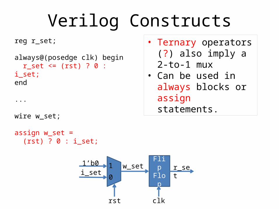
Verilog Constructsreg r_set; always@(posedge clk) begin r_set <= (rst) ? 0 : i_set;end
...
wire w_set;
assign w_set = (rst) ? 0 : i_set;
• Ternary operators (?) also imply a 2-to-1 mux
• Can be used in always blocks or assign statements.
1’b0i_set
rst
w_set FlipFlop
r_set
clk
1
0
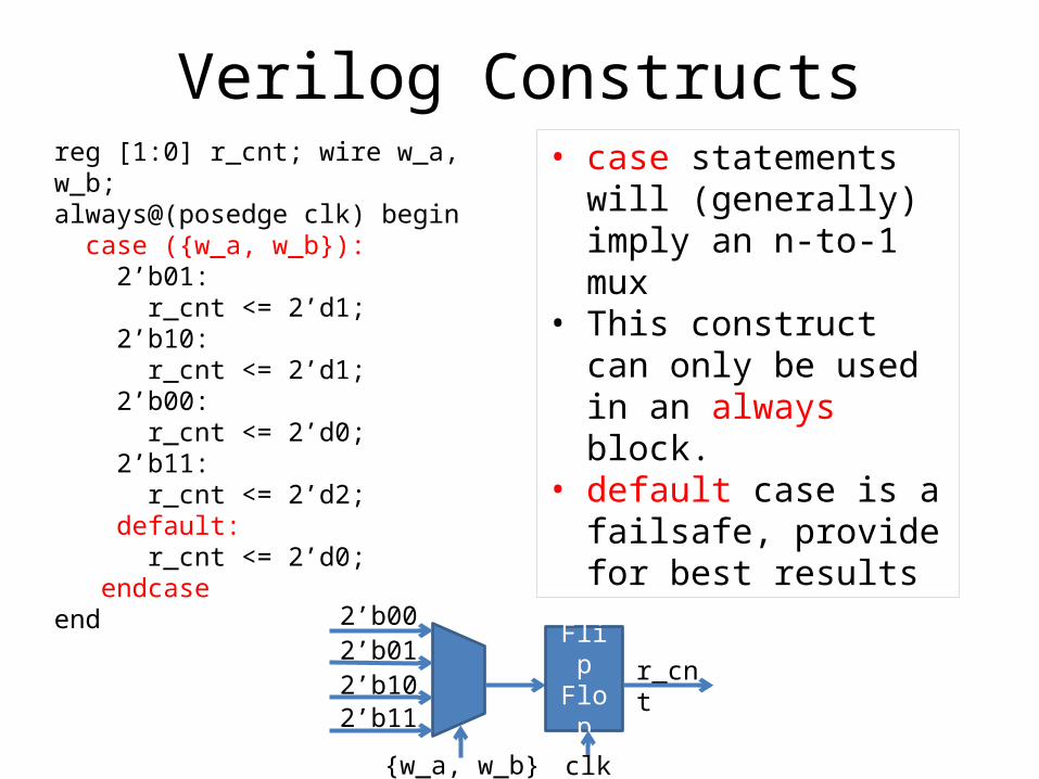
Verilog Constructsreg [1:0] r_cnt; wire w_a, w_b;always@(posedge clk) begin case ({w_a, w_b}): 2’b01: r_cnt <= 2’d1; 2’b10: r_cnt <= 2’d1; 2’b00: r_cnt <= 2’d0; 2’b11: r_cnt <= 2’d2; default: r_cnt <= 2’d0; endcaseend
• case statements will (generally) imply an n-to-1 mux
• This construct can only be used in an always block.
• default case is a failsafe, provide for best results
2’b002’b01
{w_a, w_b}
2’b102’b11
FlipFlop
r_cnt
clk
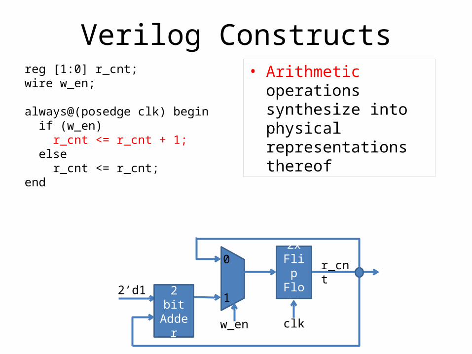
Verilog Constructsreg [1:0] r_cnt;wire w_en;
always@(posedge clk) begin if (w_en) r_cnt <= r_cnt + 1; else r_cnt <= r_cnt;end
• Arithmetic operations synthesize into physical representations thereof
2’d1
2x Flip
Flops
r_cnt
w_en
2 bitAdder
1
0
clk
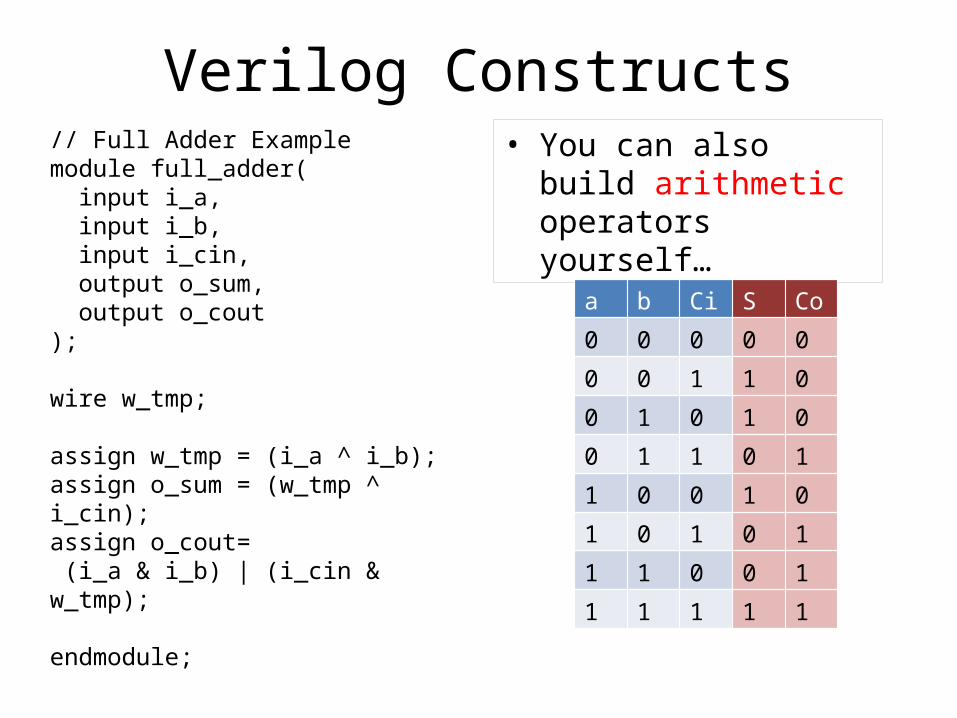
Verilog Constructs// Full Adder Examplemodule full_adder( input i_a, input i_b, input i_cin, output o_sum, output o_cout);
wire w_tmp;
assign w_tmp = (i_a ^ i_b);assign o_sum = (w_tmp ^ i_cin);assign o_cout= (i_a & i_b) | (i_cin & w_tmp); endmodule;
• You can also build arithmetic operators yourself…
a b Ci S Co
0 0 0 0 0
0 0 1 1 0
0 1 0 1 0
0 1 1 0 1
1 0 0 1 0
1 0 1 0 1
1 1 0 0 1
1 1 1 1 1
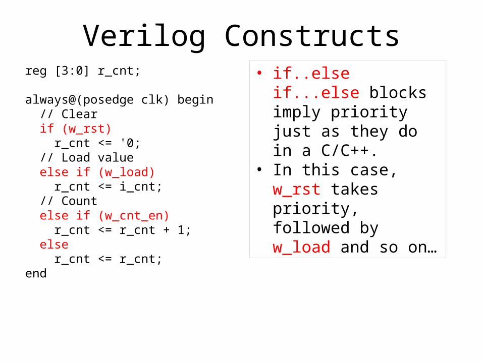
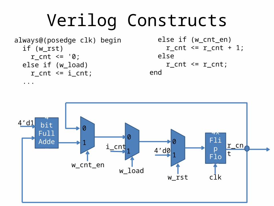
Verilog Constructsreg [3:0] r_cnt; always@(posedge clk) begin // Clear if (w_rst) r_cnt <= '0; // Load value else if (w_load) r_cnt <= i_cnt; // Count else if (w_cnt_en) r_cnt <= r_cnt + 1; else r_cnt <= r_cnt;end
• if..else if...else blocks imply priority just as they do in a C/C++.
• In this case, w_rst takes priority, followed by w_load and so on…
Verilog Constructs
4x Flip
Flops
w_rst
4’d0
w_load
i_cnt
w_cnt_en
4 bitFull
Adder
4’d1
r_cnt
always@(posedge clk) begin if (w_rst) r_cnt <= '0; else if (w_load) r_cnt <= i_cnt; ...
else if (w_cnt_en) r_cnt <= r_cnt + 1; else r_cnt <= r_cnt;end
00
011 1
clk
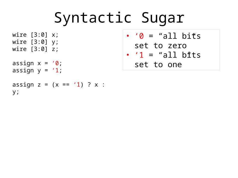
Syntactic Sugarwire [3:0] x;wire [3:0] y;wire [3:0] z;
assign x = ‘0;assign y = ‘1;
assign z = (x == ‘1) ? x : y;
• ‘0 = “all bits set to zero”• ‘1 = “all bits set to one”
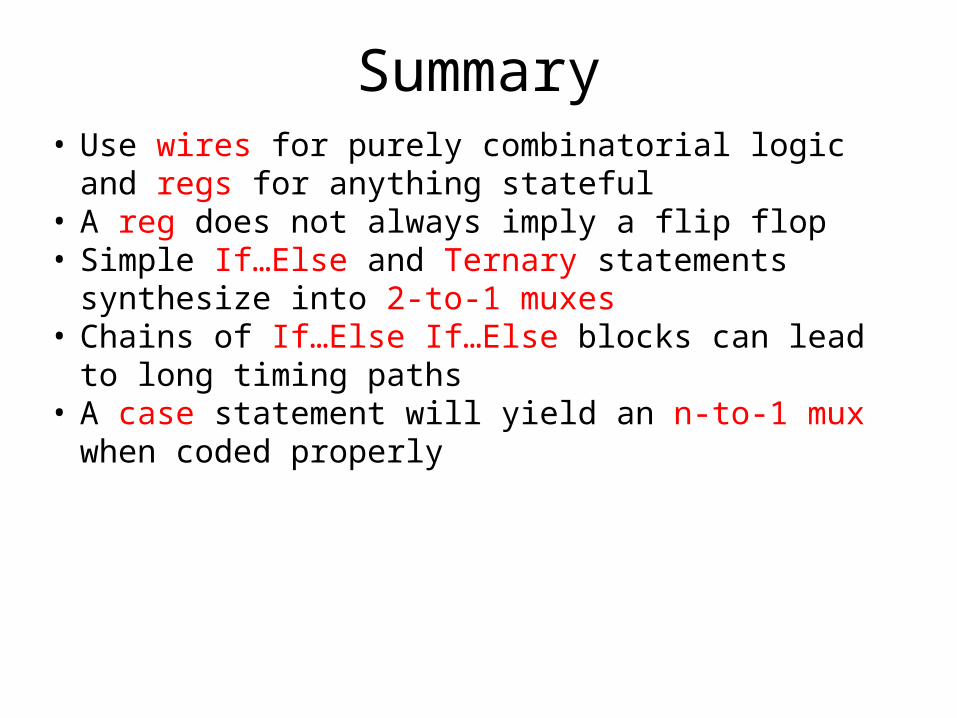
Summary• Use wires for purely combinatorial logic and regs for
anything stateful• A reg does not always imply a flip flop• Simple If…Else and Ternary statements synthesize into
2-to-1 muxes• Chains of If…Else If…Else blocks can lead to long
timing paths• A case statement will yield an n-to-1 mux when coded
properly

Questions
Exercise 2Binary Counter Modification
clki_en
o_cnt 1 2 … 14 15 14 13 01 1… …
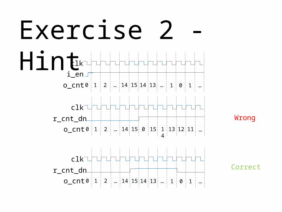
Exercise 2 - Hint
clk
r_cnt_dno_cnt 1 2 … 14 15 0 15 1213 1114 …
clk
r_cnt_dno_cnt 1 2 … 14 15 14 13 01 1… …
0
0
0
Wrong
Correct
Exercise 3FPGA build flow