Embed Size (px)
Citation preview
Introduction to Electrical drives
Electromechanical Converter System
• Electrical energy input from the source = Mechanical Energy Output + Increased in stored energy in coupling field + Energy losses
• % Overall Efficiency = ( Pmech / Pelect ) ? 100
• Losses (a) Loss in the winding resistance of the energy converter (b) Core loss (c ) Friction and Windage loss
mywbut.com
1
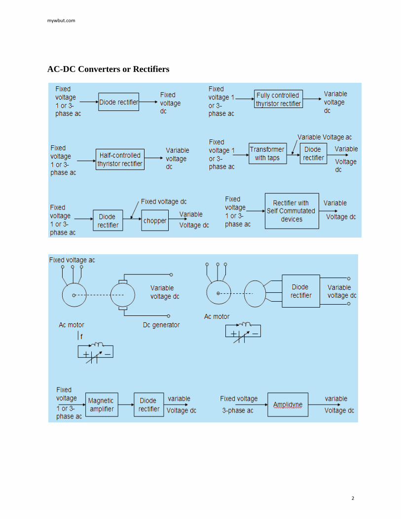
AC-DC Converters or Rectifiers
mywbut.com
2
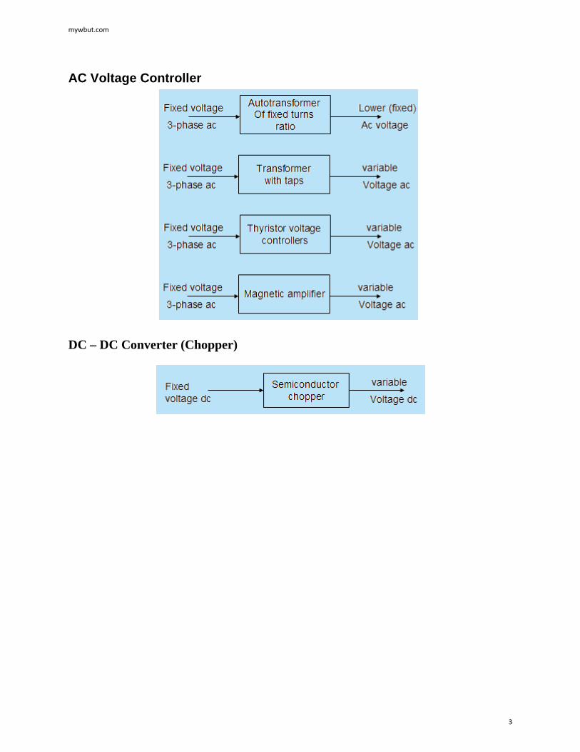
AC Voltage Controller
DC – DC Converter (Chopper)
mywbut.com
3
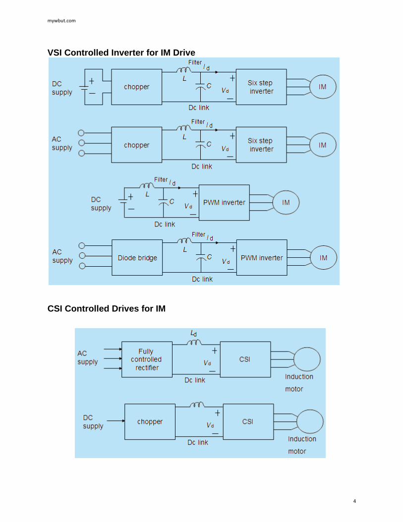
VSI Controlled Inverter for IM Drive
CSI Controlled Drives for IM
mywbut.com
4
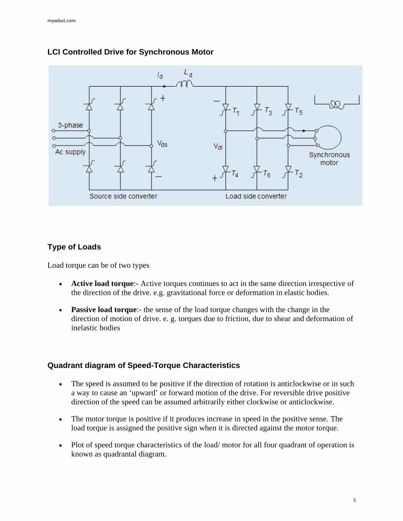
LCI Controlled Drive for Synchronous Motor
Type of Loads
Load torque can be of two types
• Active load torque:- Active torques continues to act in the same direction irrespective of the direction of the drive. e.g. gravitational force or deformation in elastic bodies.
• Passive load torque:- the sense of the load torque changes with the change in the direction of motion of drive. e. g. torques due to friction, due to shear and deformation of inelastic bodies
Quadrant diagram of Speed-Torque Characteristics
• The speed is assumed to be positive if the direction of rotation is anticlockwise or in such a way to cause an ‘upward’ or forward motion of the drive. For reversible drive positive direction of the speed can be assumed arbitrarily either clockwise or anticlockwise.
• The motor torque is positive if it produces increase in speed in the positive sense. The load torque is assigned the positive sign when it is directed against the motor torque.
• Plot of speed torque characteristics of the load/ motor for all four quadrant of operation is known as quadrantal diagram.
mywbut.com
5
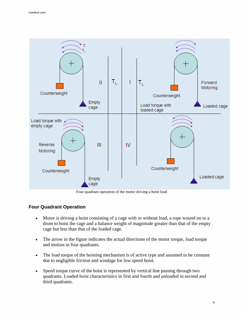
Four quadrant operation of the motor driving a hoist load
Four Quadrant Operation
• Motor is driving a hoist consisting of a cage with or without load, a rope wound on to a drum to hoist the cage and a balance weight of magnitude greater than that of the empty cage but less than that of the loaded cage.
• The arrow in the figure indicates the actual directions of the motor torque, load torque and motion in four quadrants.
• The load torque of the hoisting mechanism is of active type and assumed to be constant due to negligible friction and windage for low speed hoist.
• Speed torque curve of the hoist is represented by vertical line passing through two quadrants. Loaded hoist characteristics in first and fourth and unloaded in second and third quadrants.
mywbut.com
6
• In the first quadrant the load torque acts in the opposite direction to that of rotation. Hence to drive the loaded hoist up, the motor developed torque must be in the direction of the rotation or must be positive. The power will also be positive so, this quadrant is known as ‘forward motoring quadrant’.
• Speed torque curve of the hoist is represented by vertical line passing through two quadrants. Loaded hoist characteristics in first and fourth and unloaded in second and third quadrants.
• In the first quadrant the load torque acts in the opposite direction to that of rotation. Hence to drive the loaded hoist up, the motor developed torque must be in the direction of the rotation or must be positive. The power will also be positive so, this quadrant is known as ‘forward motoring quadrant’.
• The hoisting up of the unloaded cage is represented in the second quadrant. As the counterweight is heavier than the empty cage, the speed at which hoist moves upwards may reach a very high value. To avoid this, the motor torque must act in the opposite direction of rotation or motor torque must be negative. The power will be negative though the speed is positive, so this quadrant is known as ‘forward braking quadrant’.
• The third quadrant represents the downward motion of the empty cage. Downward journey will be opposed by torque due to counterweight and friction at the transmitting parts, move cage downwards the motor torque should must be in the direction of the rotation. Electric machine acts as a motor but in the reverse direction compared to first quadrant. The torque is negative as speed is increased I the negative direction, but the power is positive, this quadrant is known as ‘Reverse motoring quadrant’.
• Fourth quadrant has the downward motion of the loaded cage. As loaded cage has more weight than the balanced weight to limit the speed of the motion, motor torque must have opposite polarity with respect to rotation and acts as a brake. The motor torque sign is positive, but as speed has negative direction; the power will be negative, this quadrant is designated as ‘Reverse braking quadrant’.
mywbut.com
7
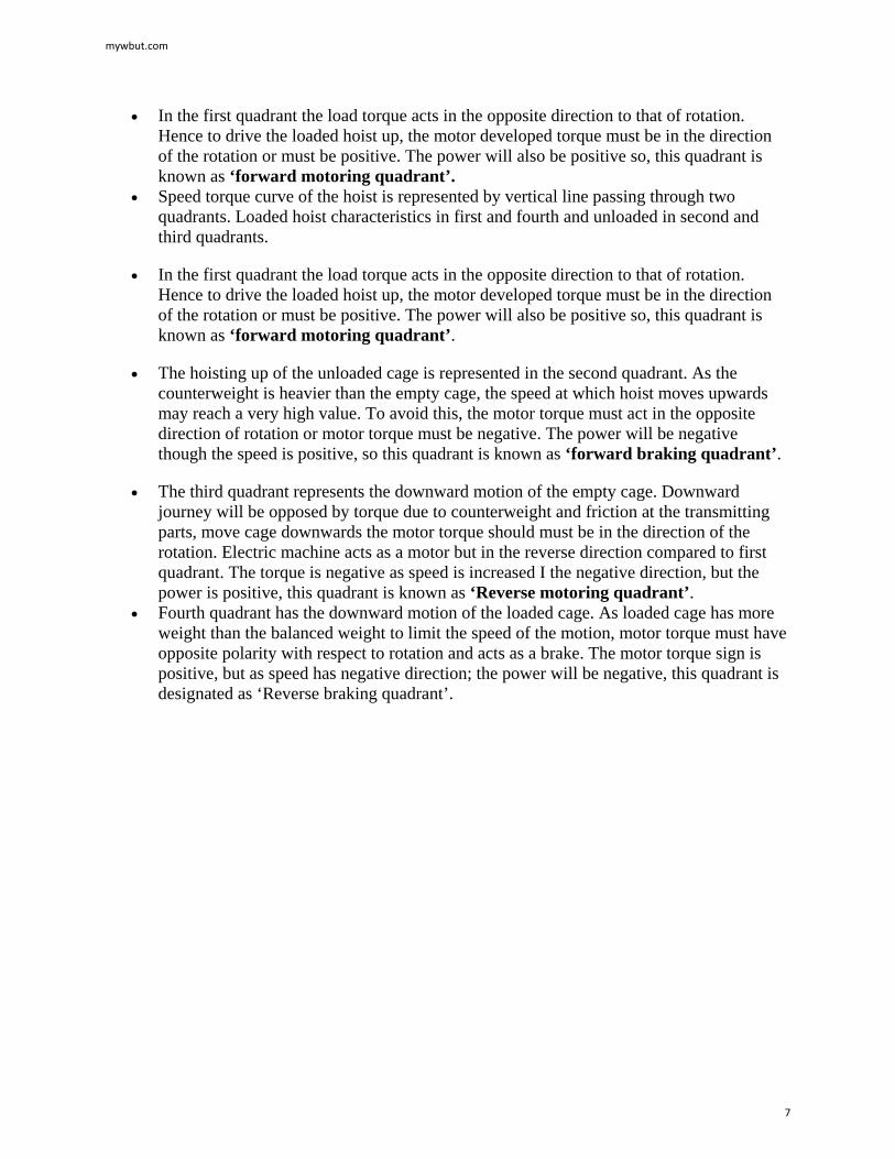
Dry Friction Load OR Coulomb Friction
• It is a passive load to the motor.
• Load torque is independent of the speed of the motor.
• Characterized by the requirement of an extra torque at very near zero speed.
• It is also known as break away torque or friction.
Viscous Friction Load
• Torque is directly proportional to the speed.
• Calendaring machines, eddy current brakes and separately excited dc generators feeding fixed resistance loads have such characteristics.
mywbut.com
8
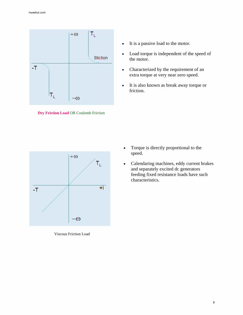
Fan type Load
• Load torque magnitude is proportional to some power of speed.
• Centrifugal pumps, propeller in ships or aeroplanes, fan or blower type of load has such characteristics.
• For fan,
mywbut.com
9
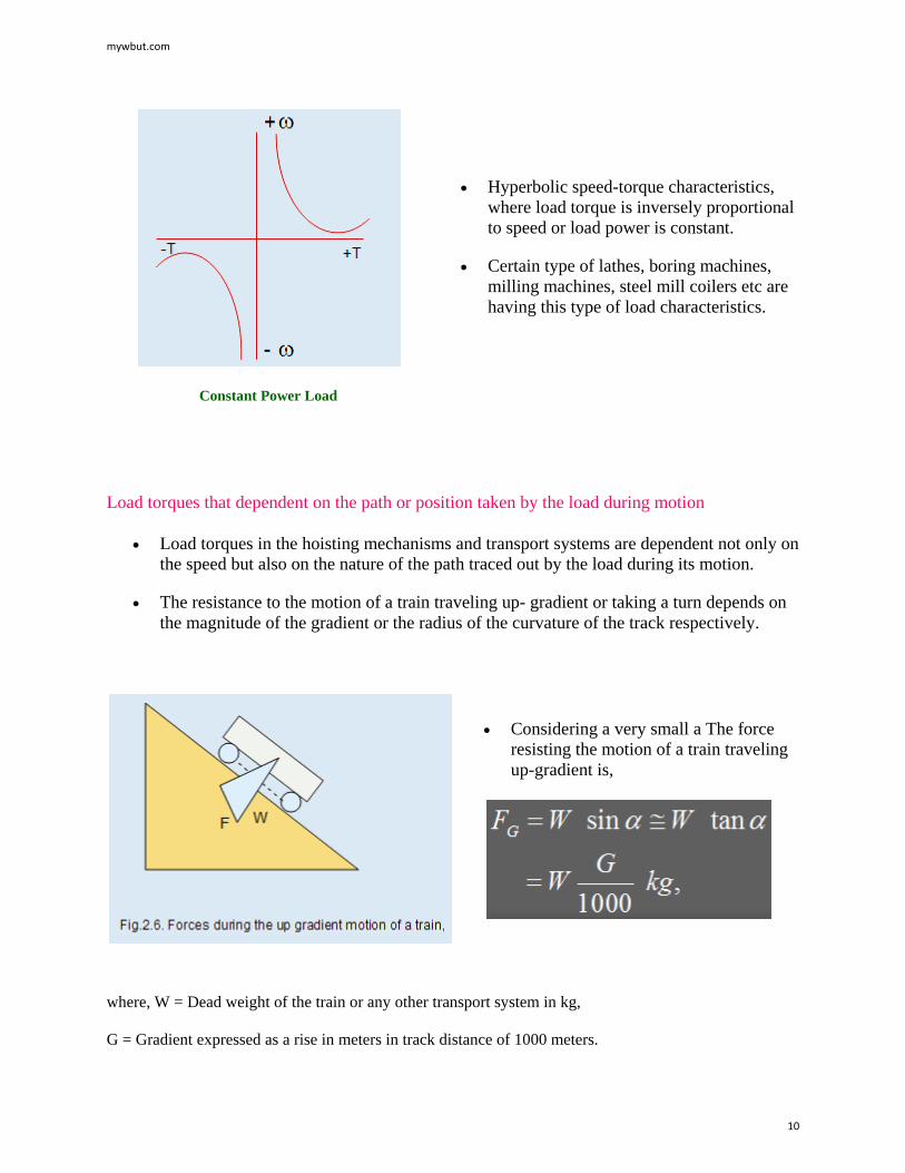
Constant Power Load
• Hyperbolic speed-torque characteristics, where load torque is inversely proportional to speed or load power is constant.
• Certain type of lathes, boring machines, milling machines, steel mill coilers etc are having this type of load characteristics.
Load torques that dependent on the path or position taken by the load during motion
• Load torques in the hoisting mechanisms and transport systems are dependent not only on the speed but also on the nature of the path traced out by the load during its motion.
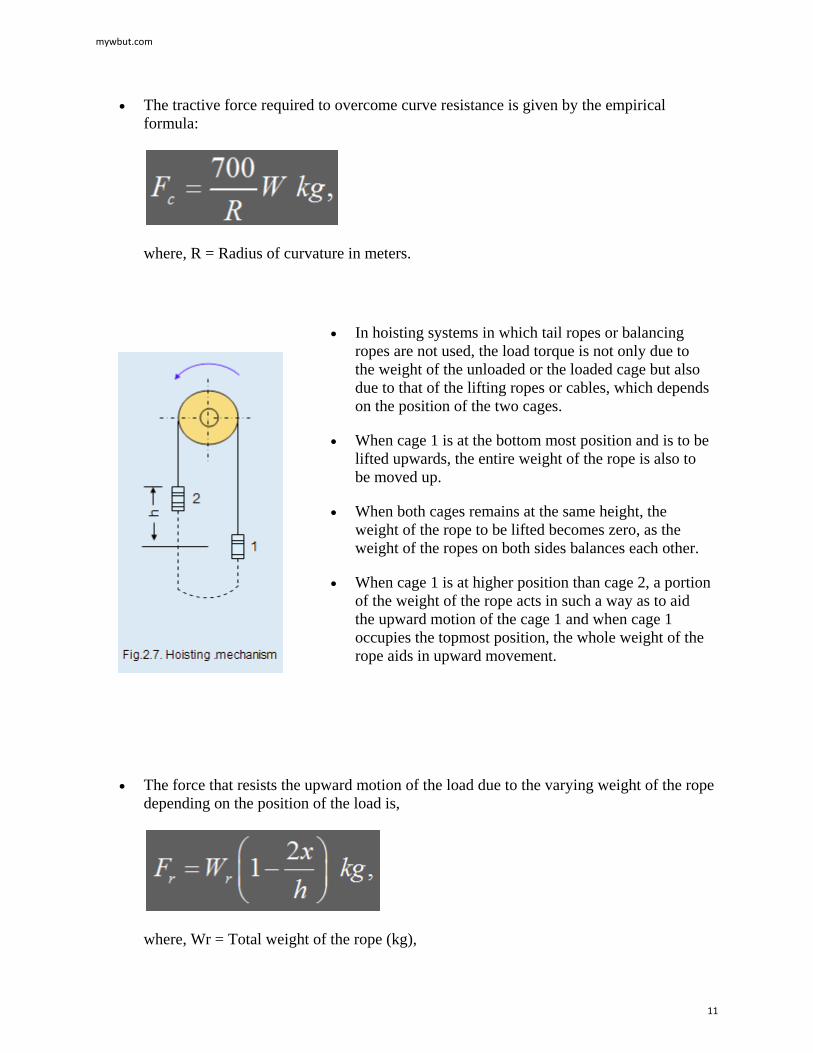
• The resistance to the motion of a train traveling up- gradient or taking a turn depends on the magnitude of the gradient or the radius of the curvature of the track respectively.
• Considering a very small a The force resisting the motion of a train traveling up-gradient is,
where, W = Dead weight of the train or any other transport system in kg, G = Gradient expressed as a rise in meters in track distance of 1000 meters.
mywbut.com
10
• The tractive force required to overcome curve resistance is given by the empirical formula:
where, R = Radius of curvature in meters.
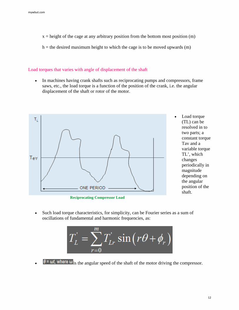
• In hoisting systems in which tail ropes or balancing ropes are not used, the load torque is not only due to the weight of the unloaded or the loaded cage but also due to that of the lifting ropes or cables, which depends on the position of the two cages.
• When cage 1 is at the bottom most position and is to be lifted upwards, the entire weight of the rope is also to be moved up.
• When both cages remains at the same height, the weight of the rope to be lifted becomes zero, as the weight of the ropes on both sides balances each other.
• When cage 1 is at higher position than cage 2, a portion of the weight of the rope acts in such a way as to aid the upward motion of the cage 1 and when cage 1 occupies the topmost position, the whole weight of the rope aids in upward movement.
• The force that resists the upward motion of the load due to the varying weight of the rope depending on the position of the load is,
where, Wr = Total weight of the rope (kg),
mywbut.com
11
x = height of the cage at any arbitrary position from the bottom most position (m) h = the desired maximum height to which the cage is to be moved upwards (m)
Load torques that varies with angle of displacement of the shaft
• In machines having crank shafts such as reciprocating pumps and compressors, frame saws, etc., the load torque is a function of the position of the crank, i.e. the angular displacement of the shaft or rotor of the motor.
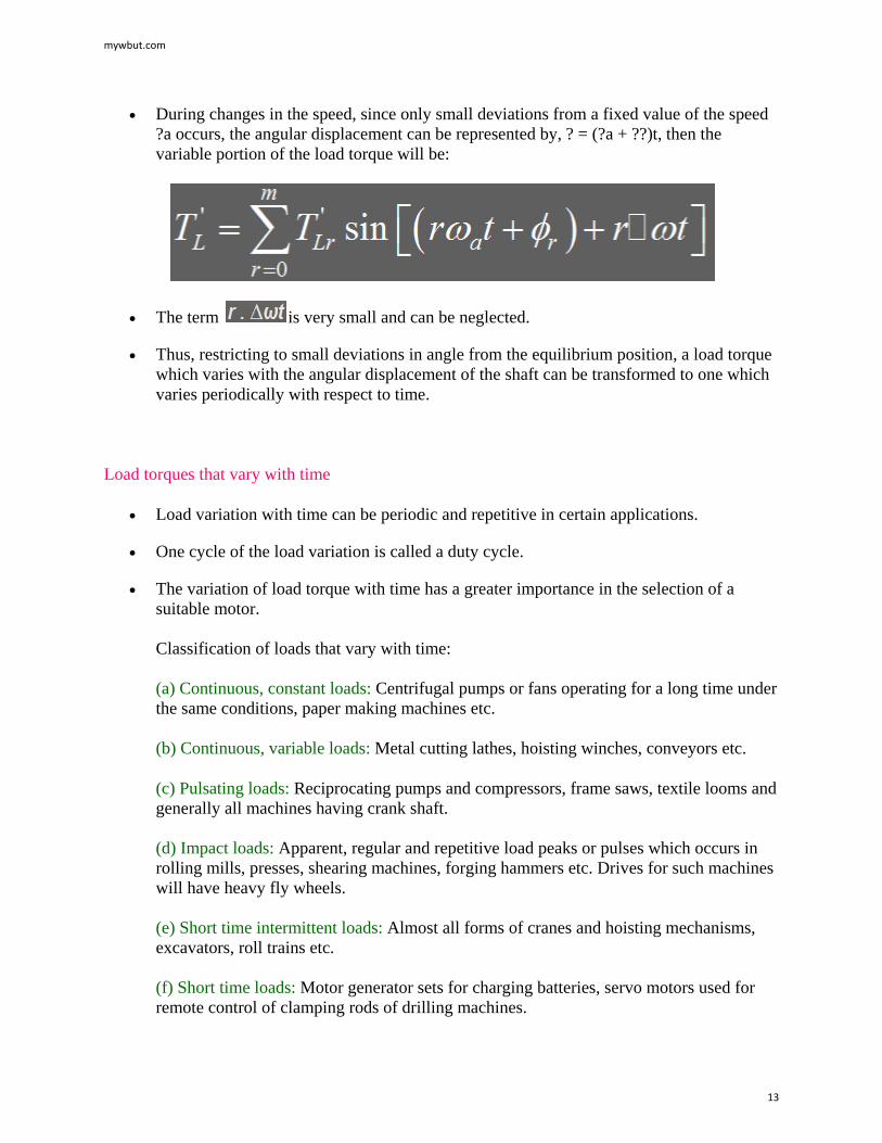
Reciprocating Compressor Load
• Load torque (TL) can be resolved in to two parts; a constant torque Tav and a variable torque TL’, which changes periodically in magnitude depending on the angular position of the shaft.
• Such load torque characteristics, for simplicity, can be Fourier series as a sum of oscillations of fundamental and harmonic frequencies, as:
• is the angular speed of the shaft of the motor driving the compressor.
mywbut.com
12
• During changes in the speed, since only small deviations from a fixed value of the speed ?a occurs, the angular displacement can be represented by, ? = (?a + ??)t, then the variable portion of the load torque will be:
• The term is very small and can be neglected.
• Thus, restricting to small deviations in angle from the equilibrium position, a load torque which varies with the angular displacement of the shaft can be transformed to one which varies periodically with respect to time.
Load torques that vary with time
• Load variation with time can be periodic and repetitive in certain applications.
• One cycle of the load variation is called a duty cycle.
• The variation of load torque with time has a greater importance in the selection of a suitable motor. Classification of loads that vary with time: (a) Continuous, constant loads: Centrifugal pumps or fans operating for a long time under the same conditions, paper making machines etc. (b) Continuous, variable loads: Metal cutting lathes, hoisting winches, conveyors etc.
(c) Pulsating loads: Reciprocating pumps and compressors, frame saws, textile looms and generally all machines having crank shaft. (d) Impact loads: Apparent, regular and repetitive load peaks or pulses which occurs in rolling mills, presses, shearing machines, forging hammers etc. Drives for such machines will have heavy fly wheels. (e) Short time intermittent loads: Almost all forms of cranes and hoisting mechanisms, excavators, roll trains etc. (f) Short time loads: Motor generator sets for charging batteries, servo motors used for remote control of clamping rods of drilling machines.
mywbut.com
13
• Loads of the machines like stone crushers and ball mills are characterized by frequent impact of small peaks so they are classified as continuous variable loads rather than the impact loads
• One and the same machine can be represented by a load torque which either varies with the speed or with the time.
• For example, a fan load whose load torque is proportional to the square of the speed, is also a continuous, constant load.
• Load torque of a crane is independent of the speed and also short time intermittent nature.
• Rocking pumps for petroleum have a load which vary with angular position of the shaft, but also be classified as a pulsating load.
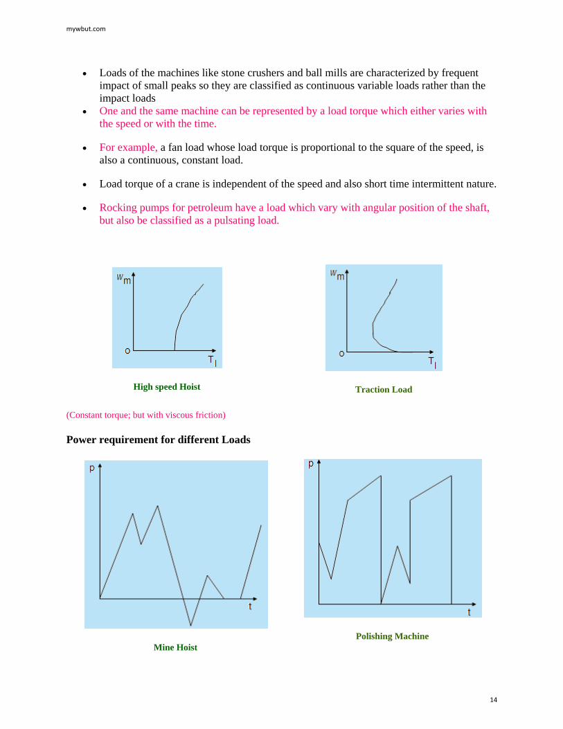
High speed Hoist
Traction Load
(Constant torque; but with viscous friction)
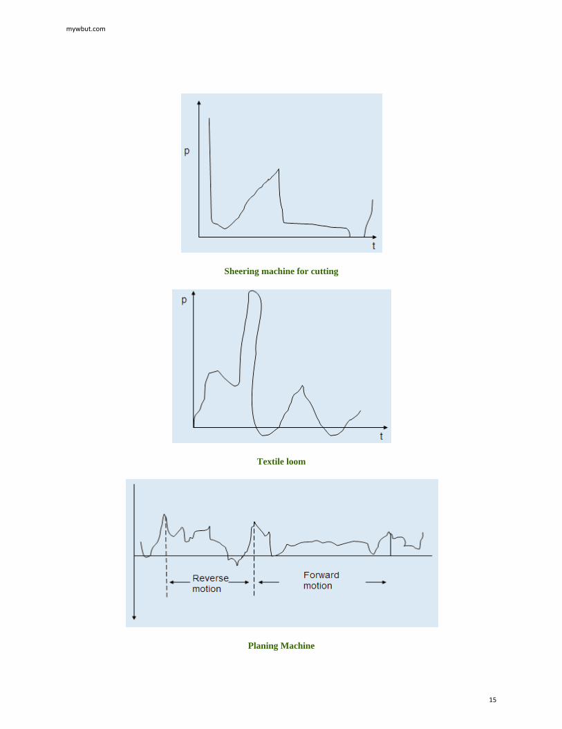
Power requirement for different Loads
Mine Hoist
Polishing Machine
mywbut.com
14
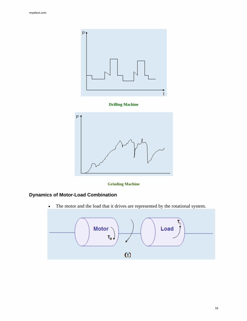
Sheering machine for cutting
Textile loom
Planing Machine
mywbut.com
15
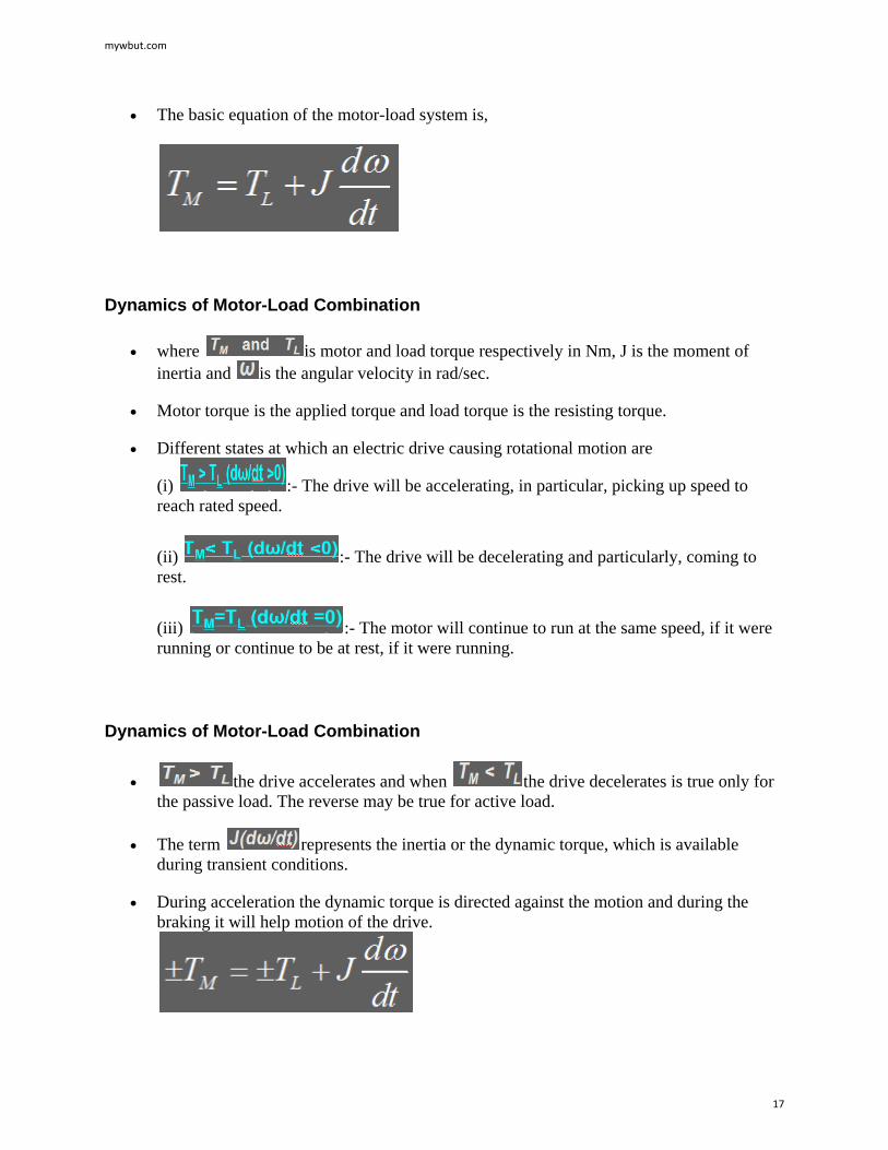
Drilling Machine
Grinding Machine
Dynamics of Motor-Load Combination
• The motor and the load that it drives are represented by the rotational system.
mywbut.com
16
• The basic equation of the motor-load system is,
Dynamics of Motor-Load Combination
• where is motor and load torque respectively in Nm, J is the moment of inertia and is the angular velocity in rad/sec.
• Motor torque is the applied torque and load torque is the resisting torque.
• Different states at which an electric drive causing rotational motion are
(i) :- The drive will be accelerating, in particular, picking up speed to reach rated speed.
(ii) :- The drive will be decelerating and particularly, coming to rest.
(iii) :- The motor will continue to run at the same speed, if it were running or continue to be at rest, if it were running.
Dynamics of Motor-Load Combination
• the drive accelerates and when the drive decelerates is true only for the passive load. The reverse may be true for active load.
• The term represents the inertia or the dynamic torque, which is available during transient conditions.
• During acceleration the dynamic torque is directed against the motion and during the braking it will help motion of the drive.
mywbut.com
17
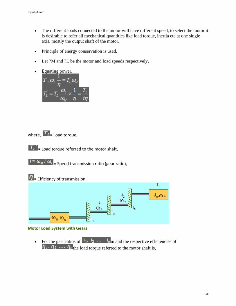
• The different loads connected to the motor will have different speed, to select the motor it is desirable to refer all mechanical quantities like load torque, inertia etc at one single axis, mostly the output shaft of the motor.
• Principle of energy conservation is used.
• Let ?M and ?L be the motor and load speeds respectively,
• Equating power,
where, = Load torque,
= Load torque referred to the motor shaft,
= Speed transmission ratio (gear ratio),
= Efficiency of transmission.
Motor Load System with Gears
• For the gear ratios of in and the respective efficiencies of the load torque referred to the motor shaft is,
mywbut.com
18
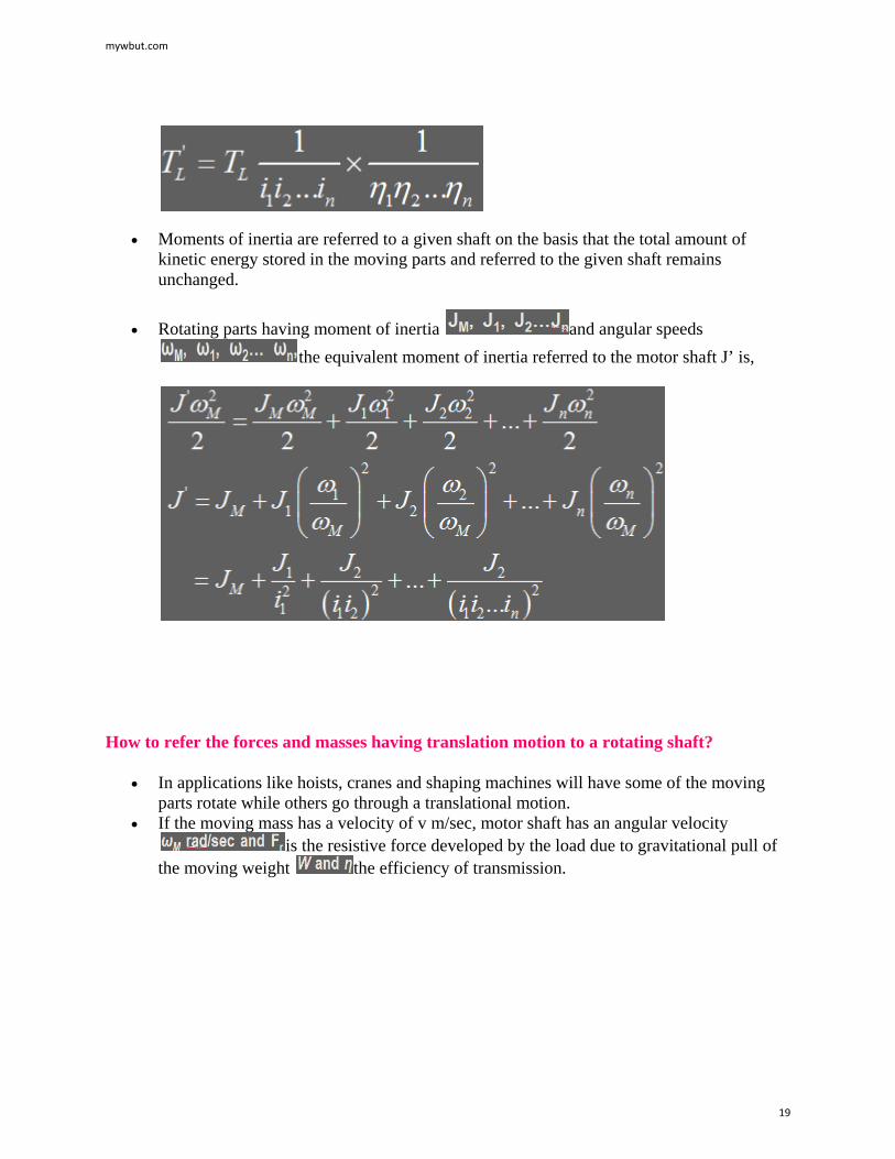
• Moments of inertia are referred to a given shaft on the basis that the total amount of kinetic energy stored in the moving parts and referred to the given shaft remains unchanged.
• Rotating parts having moment of inertia and angular speeds the equivalent moment of inertia referred to the motor shaft J’ is,
How to refer the forces and masses having translation motion to a rotating shaft?
• In applications like hoists, cranes and shaping machines will have some of the moving parts rotate while others go through a translational motion.
• If the moving mass has a velocity of v m/sec, motor shaft has an angular velocity is the resistive force developed by the load due to gravitational pull of
the moving weight the efficiency of transmission.
mywbut.com
19
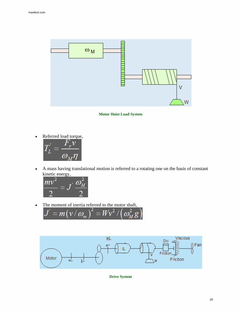
Motor Hoist Load System
• Referred load torque,
• A mass having translational motion is referred to a rotating one on the basis of constant kinetic energy,
• The moment of inertia referred to the motor shaft,
Drive System
mywbut.com
20
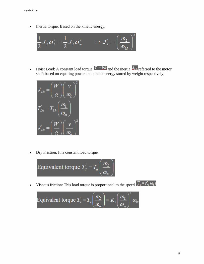
• Inertia torque: Based on the kinetic energy,
• Hoist Load: A constant load torque and the inertia referred to the motor shaft based on equating power and kinetic energy stored by weight respectively,
• Dry Friction: It is constant load torque,
• Viscous friction: This load torque is proportional to the speed
mywbut.com
21
• Fan: Load torque of the fan is proportional to square of speed
• Fan: Load torque of the fan is proportional to square of speed
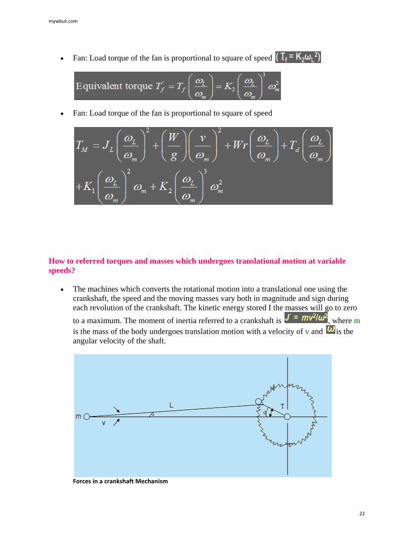
How to referred torques and masses which undergoes translational motion at variable speeds?
• The machines which converts the rotational motion into a translational one using the crankshaft, the speed and the moving masses vary both in magnitude and sign during each revolution of the crankshaft. The kinetic energy stored I the masses will go to zero to a maximum. The moment of inertia referred to a crankshaft is , where m is the mass of the body undergoes translation motion with a velocity of v and is the angular velocity of the shaft.
Forces in a crankshaft Mechanism
mywbut.com
22

• The relationship between the linear velocity of the piston v and the angular speed of the crankshaft is,
• The moment of inertia refereed to crankshaft,
• The load torque referred to the motor shaft is,
where, F is the resisting force applied by the part which undergoes translational motion, i is the gear ratio and is the efficiency of transmission.
• For the mechanism having crankshaft, the equation of motion will be,
• Kinetic energy stored in the crankshaft
• The dynamic power and the inertia torque is
• Initial kinetic energy stored in the system will be used to supply the rotational losses and gradually speed reduces to zero.
mywbut.com
23
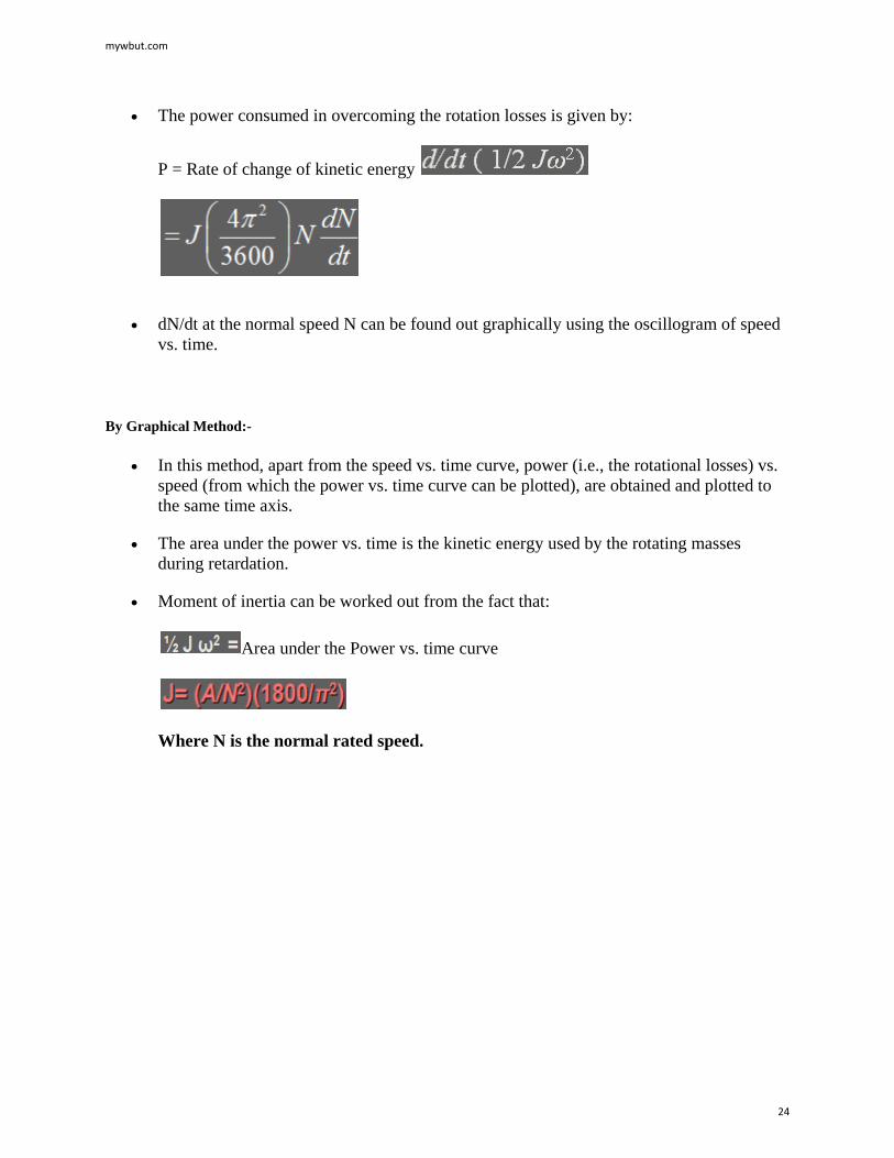
• The power consumed in overcoming the rotation losses is given by:
P = Rate of change of kinetic energy
• dN/dt at the normal speed N can be found out graphically using the oscillogram of speed vs. time.
By Graphical Method:-
• In this method, apart from the speed vs. time curve, power (i.e., the rotational losses) vs. speed (from which the power vs. time curve can be plotted), are obtained and plotted to the same time axis.
• The area under the power vs. time is the kinetic energy used by the rotating masses during retardation.
• Moment of inertia can be worked out from the fact that:
Area under the Power vs. time curve
Where N is the normal rated speed.
mywbut.com
24
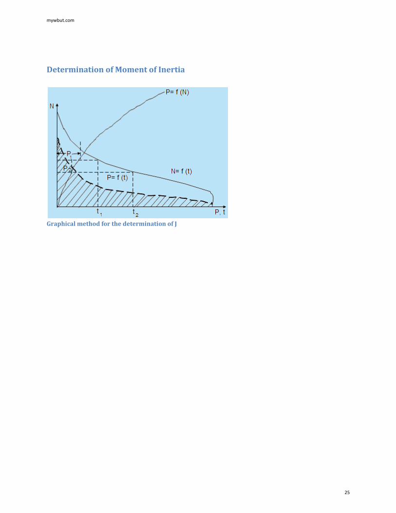
Determination of Moment of Inertia
Graphical method for the determination of J
mywbut.com
25


![Advantages of profiled rail guide Loads and load torques€¦ · Loads and load torques Designation B 40-ZSS Max. travel speed [m/s] 3 ... SCHUNK can supply you with the right motor](https://img.pdfslide.us/doc/110x75/5eb5cd7e4435c960002ef8c4/advantages-of-profiled-rail-guide-loads-and-load-torques-loads-and-load-torques.jpg)