Embed Size (px)
Citation preview

1
Introduction to Digital Subscriber Lines
Wen-Rong WuDept. of Communication Engineering
National Chiao Tung University
2
Contents
1. Introduction2. Subscriber Loop Environment3. Transmission and Signal Processing4. Standards

3
1. Introduction
! Telephone service was first provided by A. G. Bell in 1877.Now, about 740 million subscriber lines exist in the world(according to ITU) and 73% of them are for residential use.In U.S., there are 160 million lines.
! Originally, the public switched telephone network (PSTN)is developed for analog speech signals. Thus, only low-speed digital transmission is allowed.
! However, due to the advance of silicon and digital signalprocessing technology, high-speed transmission now ispossible.
4
! Growth of the transmission rate:

5
! Motivation for higher bit rates:– Growth of PC
6
– Internet access
7
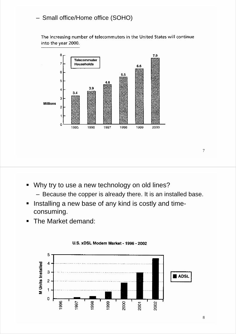
– Small office/Home office (SOHO)
8
! Why try to use a new technology on old lines?– Because the copper is already there. It is an installed base.
! Installing a new base of any kind is costly and time-consuming.
! The Market demand:

9
! There are three ways to provide digital access through thetelephone subscriber line.
! Analog (modem):
10
! Digital (ISDN):

11
! Both (DSL):
12
2. Subscribe Loop Environment
! Telephone network:
13
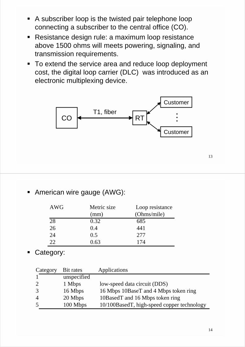
! A subscriber loop is the twisted pair telephone loopconnecting a subscriber to the central office (CO).
! Resistance design rule: a maximum loop resistanceabove 1500 ohms will meets powering, signaling, andtransmission requirements.
! To extend the service area and reduce loop deploymentcost, the digital loop carrier (DLC) was introduced as anelectronic multiplexing device.
CO RT
Customer
Customer
MT1, fiber
14
! American wire gauge (AWG):
! Category:
AWG Metric size Loop resistance(mm) (Ohms/mile)
28 0.32 68526 0.4 44124 0.5 27722 0.63 174
Category Bit rates Applications1 unspecified2 1 Mbps low-speed data circuit (DDS)3 16 Mbps 16 Mbps 10BaseT and 4 Mbps token ring4 20 Mbps 10BasedT and 16 Mbps token ring5 100 Mbps 10/100BasedT, high-speed copper technology
15
! The carrier serving area (CSA) design rule (for DLCloops) :– The maximum CSA loop length is 12 Kft for 24 AWG.– The maximum CSA loop length is 9 Kft for 26 AWG.
! Speech signal is digitized at the CO with a rate of 64 Kb/s(8 bits x 8 K).
! Due to the quantization noise, the analog modem speedcannot exceed 56 Kb/s.
! Digital data between COs are usually communicatedusing optic fibers.
16
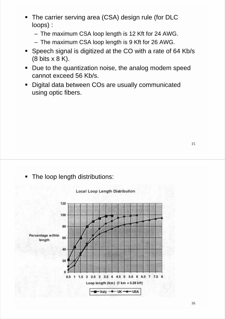
! The loop length distributions:

17
! The feeder and distribution cables are bundled into bindergroups 25, 50, and 100 pairs.
! It is common practice to connect a twist-pair from a feedercable with more than one cables (bridged tap).
18
! For loops beyond 5.5 Km, the signal loss at frequenciesabove 1 KHz is unacceptable. Series inductors placed at1.8 Km result in a flatter spectrum at the voice band(loading coil)
0 3kHzfrequency
receivedsignalpower
loadedloop
non-loadedloop
Frequency characteristics of a loop over 18 kft long

19
! There are many impairments in the subscriber loops
– Channel distortion– Channel attenuation– Crosstalk noise– Impulsive noise– Background/thermal noise– Radio frequency interference– Echoes
20
! The channel distortion (ISI):
TelephoneChannel
Inter-symbol interference:

21
! Channel impulse responses:
22
! Channel attenuation:
DSL type Transmission Maximum Minimum receivedpeak (Volts) power loss (dB) peak (Volts)
ISDN (144kb/s) 2.5 42 0.02HDSL (1.5Mb/s) 2.5 35 0.045ADSL (1.5Mb/s) 15 45 0.085VDSL (26 Mb/s) 3-4 30 0.09-0.12
23
! Since telephone subscriber loops are organized in bindergroup, there is crosstalk between each twisted pair.
! Near end crosstalk (NEXT):
! The crosstalk effect is frequency dependent. It is moreapparent for the high frequency signal components.
! It is generally accepted that NEXT is increased with f 1.5.
24
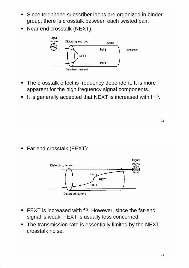
! Far end crosstalk (FEXT):
! FEXT is increased with f 2. However, since the far-endsignal is weak, FEXT is usually less concerned.
! The transmission rate is essentially limited by the NEXTcrosstalk noise.
25
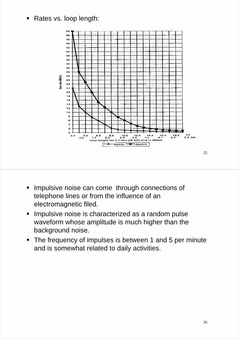
! Rates vs. loop length:
26
! Impulsive noise can come through connections oftelephone lines or from the influence of anelectromagnetic filed.
! Impulsive noise is characterized as a random pulsewaveform whose amplitude is much higher than thebackground noise.
! The frequency of impulses is between 1 and 5 per minuteand is somewhat related to daily activities.

27
! Impulse noise #1 used in test:
28
! Impulse noise #2 used in test:

29
! If the receiver is properly designed and implemented, thethermal noise level can be smaller than the backgroundnoise.
! The background noise level for the twist-pair telephoneloop plant is around -140 dBm/Hz (dBm=10 x log10(wattsx 1000)).
! The radio frequency interference comes from AM MV, AMSM, and HAM. This problem is more serious for very highspeed DSL.
30
! Echoes arises in a full-duplex transmission in a telephoneloop.
! Due to the impedance mismatch problem, echoes thusarise.
! Note that the echo power is usually much stronger thanthat of the receiver signal.
31
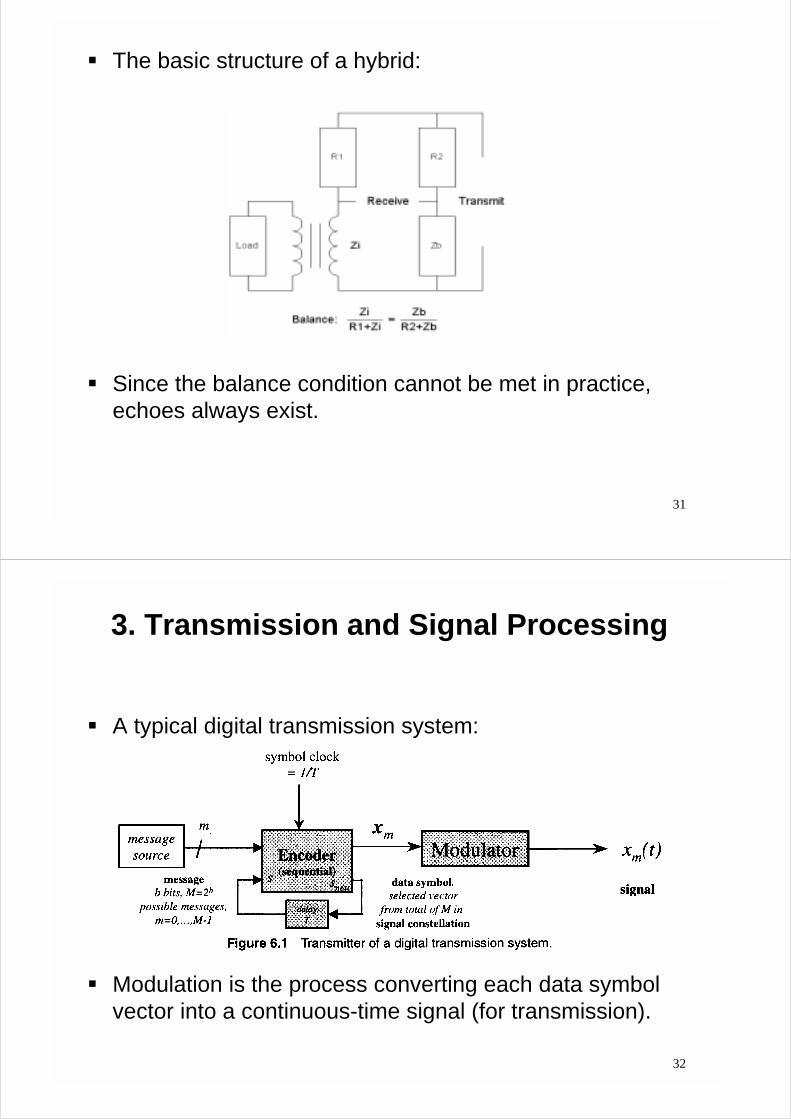
! The basic structure of a hybrid:
! Since the balance condition cannot be met in practice,echoes always exist.
32
3. Transmission and Signal Processing
! A typical digital transmission system:
! Modulation is the process converting each data symbolvector into a continuous-time signal (for transmission).

33
! The 2B1Q line code (ISDN and HDSL):– “2 bits per one quartenary” symbol
f(t) channel f(t)
11
10
01
00
11
10
01
00
four level signals(2 bits)
modulator demodulator
detectionand
decoding
encoder
﹜﹜﹜﹜
filter(SRRC)consineraisedroot-squarethecalledisThis
factoroff-rollthe:
/])/4(1[/)]1(cos[4]/)1(sin[
)(2
ααπ
απααπTTtt
TttTttf
−++−=
34
! Quadrature amplitude modulation (QAM):
where is a baseband function such as the square-root raised cosine one.
! A successive QAM signal:
! Note that the sinusoidal signals are not shifted by kT onthe k-th symbol. The basis functions are not periodic.
)2sin()(2)(
)2cos()(2)(
2
1
tωtψTtφ
tωtψTtφ
c
c
=
=
)(tψ
∑ −−−=k
ckck tωkTtψxtωkTtψxT
tx )sin()()cos()(2
)( ,2,1

35
! In the complex plane:
! Carrierless amplitude/phase modulation (CAP):– Using the complex representation, we can have QAM as
−=
−=
∑
∑
−
k
kTtωjkTωjk
k
tωjk
cc
c
ekTtψex
ekTtψxtx
)()(Re
)(Re)(
Decision region
36
! Original QAM:
! An alternative QAM
channel
x k,2
tcos cω
tsin cω
tcos cω
tsin cω
( )tψ
( )tψ ( )tψ
( )tψx k,1
channel
kTj ce ω kTj ce ω−
kxkx( )tγ ( )kTt −γ
( ) ( ) ( )kTtj cekTtψt −−= ωγ

37
! The CAP system is the result of removing the phaserotator and the phase de-rotator in a QAM system.
! Thus, there is no carrier and is simply a parameterthat indicates the center of the transmission passband.
! CAP and QAM are fundamentally equivalent inperformance - only implementation is different.
! The probability of bit error for QAM/CAP
∑ −−−−−=k
ckck kTtωkTtωxkTtωkTtψxT
tx ))(sin()())(cos()(2
)( ,2,1
cω
( )
D)-(1levelamplitudeofnumberthe:
1log2
log12
22
2
1
L
SNRL
LQ
LL
Pb
−−≅
−
38
! The CAP basis functions:

39
! The basic multichannel (muticarrier) transmission:
! Note that if occupies different frequency bands, theorthogonal conditions can be satisfied.
1X)(1 tΦ
2X)(2 tΦ
NX)(tNΦ
+ channel
)(1 tT −Φ
)(2 tT −Φ
)( tTN −Φ
1Y
2Y
NY
sti )'(Φ
40
! The simplest function is the sinusoid having a singlefrequency. Consider the sampled .
! Property:
)(Φ ti)(Φ ti
≠=
=
−===
∑−
=
−
mk
mke
N
NkNπ
en
N
n
nmkj
njkk
,0
,11
1,,1,0,2Ω,)(Φ
1
0
Ω)(
0Ω
0
0 L
nje 0Ωl
nje 0Ω− l
DFT
DFT
π2
π2
ω
ω
41
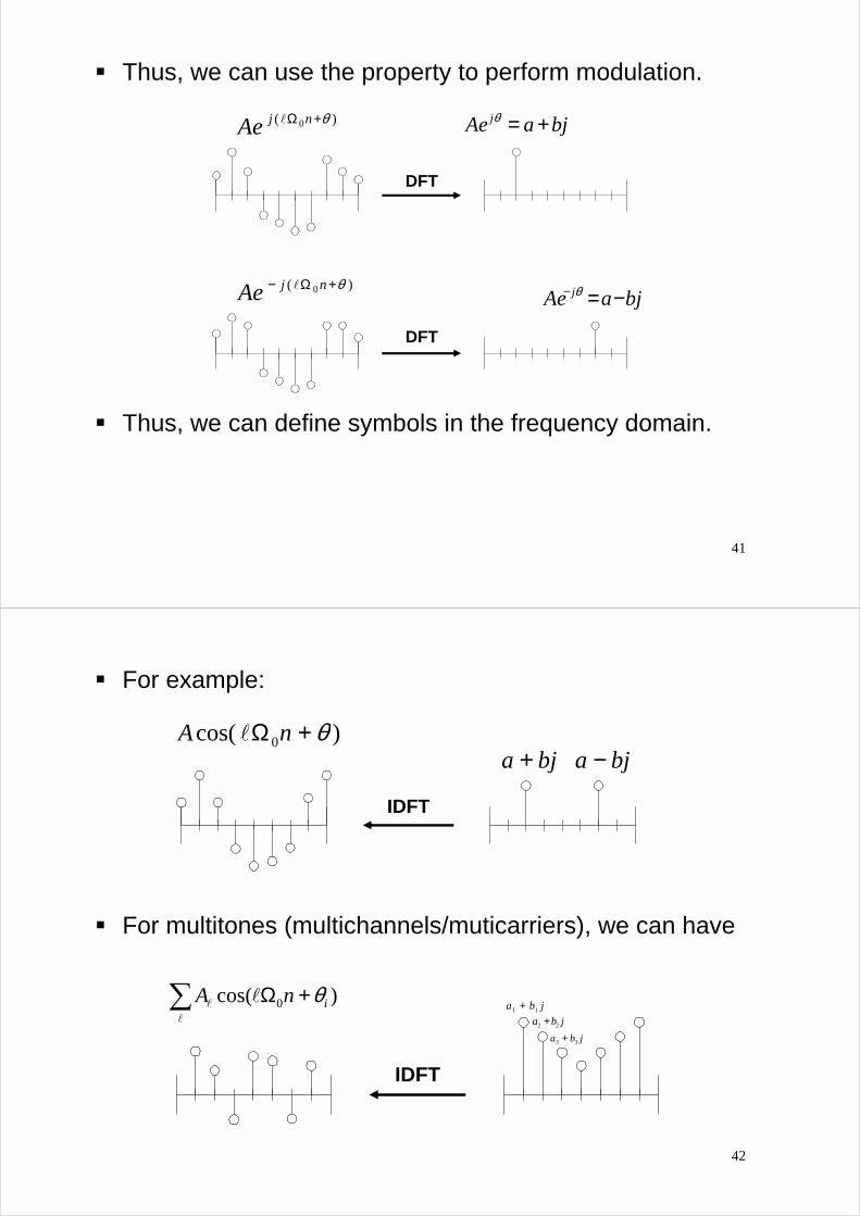
! Thus, we can use the property to perform modulation.
! Thus, we can define symbols in the frequency domain.
)( 0 θ+Ω njAe l
DFT
DFT
bjaAe j +=θ
)( 0 θ+Ω− njAe lbjaAe j −=− θ
42
! For example:
! For multitones (multichannels/muticarriers), we can have
)cos( 0 θ+Ω nA l
IDFT
bja + bja −
∑ +Ωl
l l )cos( 0 inA θ
IDFT
jba 11 +jba 22 +
jba 33 +

43
! In the receiver, we then have
! ISI:
∑ +Ωl
l l )cos( 0 inA θ
DFT
jba 11 +
channel
channel
guardinterval
ISI
no ISI
44
! To compensate the channel effect in frequency domain(circular convolution), the guard interval is
! If the channel response is known (shorter than CP), thencyclic prefix
)(
)()(
)()()(
k
k
k
ωj
ωjmωjm
mm
eH
eYeX
nhnxny
=⇒
⊗=

45
! The discrete multitone (DMT) system (ITU g.dmt, ANSIT1.413):
46
! The DMT downstream parameters:
Symbol rate 4 kHz
FFT size 512 samplesCyclic prefix 32 samplesSampling rate 2.208 MHzFrequency spacing 4.3125 KHz
! The DMT upstream parameters:
Symbol rate 4 kHzFFT size 64 samplesCyclic prefix 4 samplesSampling rate 276 KHzFrequency spacing 4.3125 KHz

47
! An equalizer is a commonly used device to compensatefor the channel effect.
! Adaptive equalizer :
Channel Equalizera(n)
w(n)
+
+)(ˆ)( ∆−= nany
x(n)
))(
1)(noise,noIf( ∆−= z
zHzE(H(z))
Channela(n)
w(n)
+
+
)( ∆−na
x(n) +_Equalizer
y(n)
48
! Adaptive echo canceller :
! Timing recovery:– The purpose of timing recovery is to recover a symbol rate
clock, which is used in the far-end transmitter D/A device,from the received waveform.
HybirdAdaptive
Filter
+
_
Transmit
Echoe(n)
u(n)
y(n)d(n)

49
! A general HDSL transceiver:
50
4. Standards
! ISDN: integrated services digital network. This can beseen as the first DSL service (since 1986).
! The low data rate ultimately become a major drawback ofthis DSL technology.
! Nevertheless, many ISDN lines still deployed (1.7 millionin 1994 and 6 million in 1996)
Kb/s160Total
(16K)controllineandFraming
packetdatauserandsignalingfor:K)(16channelD
ontransmissidatafor:K)1282(64channelB =×

51
! HDSL (high-bit rate digital subscriber loop)! HSDL was essentially up-scaled the ISDN designs. The
first HDSL service was placed in 1992.! It is now used to replace the T1 and E1 services for cost
reduction. This benefit is mainly due to the elimination ofmid-space repeaters.
CO HTU-RNetwork Users
duplex
784 kb/s
784 kb/s
Mb/s2.048:wirespairs3
Mb/s1.544:wirespairs2
52
! 2B1Q and CAP are the de-facto standards in NorthAmerica.
! 2B1Q and CAP have the same performance.! 2B1Q is the selected line code for ETSI standard.! ADSL (Asymmetric DSL)! The ADSL concept evolves during the early 1990. At first,
ADSL was considered at a fixed rate 1.5 Mb/sdownstream and 16 Kb/s upstream for MPEG-1.
! Recently, ADSL finds wide applications with the internetaccess.
wiresofpairOne
servicePOTSprovidesuslySimultaneo
Mb/s1toup:Upstream
Mb/s9toup:Downstream
53
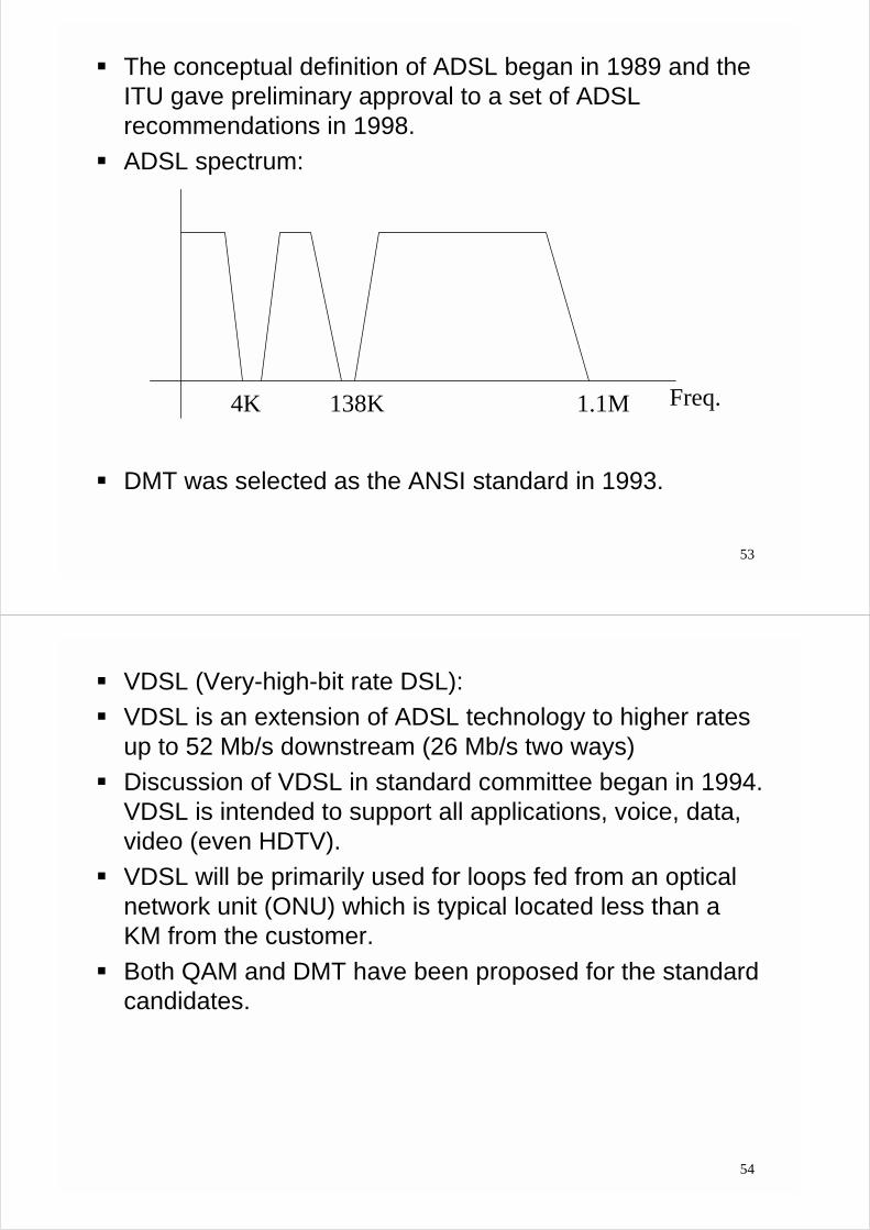
! The conceptual definition of ADSL began in 1989 and theITU gave preliminary approval to a set of ADSLrecommendations in 1998.
! ADSL spectrum:
! DMT was selected as the ANSI standard in 1993.
1.1M4K 138K Freq.
54
! VDSL (Very-high-bit rate DSL):! VDSL is an extension of ADSL technology to higher rates
up to 52 Mb/s downstream (26 Mb/s two ways)! Discussion of VDSL in standard committee began in 1994.
VDSL is intended to support all applications, voice, data,video (even HDTV).
! VDSL will be primarily used for loops fed from an opticalnetwork unit (ONU) which is typical located less than aKM from the customer.
! Both QAM and DMT have been proposed for the standardcandidates.

55
! VDSL service area:
56
! VDSL service range: