Embed Size (px)
Citation preview
Hardware structures –
external memory (mass storage),
input-output system.
Introduction to Computer Systems (5)
Piotr Mielecki Ph. D.
http://www.wssk.wroc.pl/~mielecki
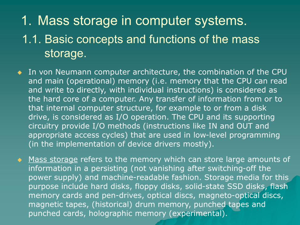
1. Mass storage in computer systems.
In von Neumann computer architecture, the combination of the CPU and main (operational) memory (i.e. memory that the CPU can read and write to directly, with individual instructions) is considered as the hard core of a computer. Any transfer of information from or to that internal computer structure, for example to or from a disk drive, is considered as I/O operation. The CPU and its supporting circuitry provide I/O methods (instructions like IN and OUT and appropriate access cycles) that are used in low-level programming (in the implementation of device drivers mostly).
Mass storage refers to the memory which can store large amounts of information in a persisting (not vanishing after switching-off the power supply) and machine-readable fashion. Storage media for this purpose include hard disks, floppy disks, solid-state SSD disks, flash memory cards and pen-drives, optical discs, magneto-optical discs, magnetic tapes, (historical) drum memory, punched tapes and punched cards, holographic memory (experimental).
1.1. Basic concepts and functions of the mass
storage.
The basic function of the mass storage was previously only the backup for the RAM operational (main) memory. The term ”second-level storage” was used for this functionality, while the operational memory was called ”first-level storage”. The example (not too ”historical”) of this approach was the tape-recorder used as mass storage for 8-bit home computers like Sinclair ZX-Spectrum or Commodore C-64. The user was loading the entire image of program (including data) from the tape using the ”LOAD” command, he could also store the program with data to tape using ”SAVE” command. In most of cases there were no readings or writings of any data from or to the tape during the program execution.
In today’s operating systems the mass storage supports at last two more sophisticated and very important functionalities:
On-line filesystem, organized usually as tree-like logical structure of directories (folders), providing access to different files for one or more running programs (processes).
Swap area, implemented as special file or separate filesystem (partition), supporting virtual memory mechanism.
The functions mentioned above are supported by magnetic, SSD and optical disk drives and flash pendrives / cards. The backup functionality of the mass storage is implemented by tape (cassette) drives, the optical disks and (sometimes) by dedicated, redundant arrays of cheap hard disks. The ”backup” means today not the saved image of main memory, but the copy (or set of copies) of the data stored normally in the on-line mass storage system.
To implement the functionalities mentioned above we should consider several different levels of specification (technical parameters of devices, requests for software modules etc.):
Physical structure of the storage device – the class of the device (disk, tape drive etc.), the access method (sequential, random or semi-random access – see chapter 1.2.), organization of the particular device (geometry of the disk, for example).
Physical interface between the device and CPU + main memory structure (standard bus like ATAPI/EIDE, SATA, SCSI, SAS etc.).
Possible aggregation of the storage devices – in case of RAID arrays, the aggregation can be supported by appropriate hardware (array disk controllers) or by system software using non-array disk controllers (”soft” RAID), finally we should consider the entire array as a single physical device.
Next levels of specification:
Low-level format – the interface to the physical organization of the device (disk plates, heads, tracks, sectors). In older disks (the 1980-ties and early 1990-ties) it was done by writing the appropriate control impulses to distinguish the beginning and the end of each sector and the user was often performing this operation by himself (using a special software or BIOS routine). Most modern hard disks are embedded systems, which are low-level formatted at the factory with the physical geometry dimensions and thus not subject to user intervention.
Logical segmentation of the device – usually means the division of the physical storage area into a set of logical areas (partitions and volumes). The low-level format and partitioning must fit the requests of the high-level format (see below).
High-level format – interface between partitions and sectors and the file-level access methods, appropriate for the chosen filesystem (like FAT32, NTFS, HPFS, ext3, ext4, Raiser FS etc.). It uses logical allocation blocks (the minimum sets of data which can be accessed by a single read or write access cycle), mapped to particular files. The smallest logical allocation block on the disk (cluster) is in most of cases a set of aggregated physical sectors, 4096 bytes typically.
Sector Track
Head positioning
Head Cylinder
Plate
Head 0
Head 1 Plate 0
Plate 1
Plate 2
Plate 3
Head 0
Head 1
Head 0
Head 1
Head 0
Head 1
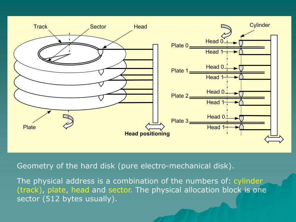
Geometry of the hard disk (pure electro-mechanical disk).
The physical address is a combination of the numbers of: cylinder (track), plate, head and sector. The physical allocation block is one sector (512 bytes usually).
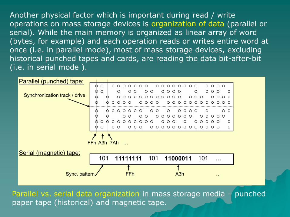
Another physical factor which is important during read / write operations on mass storage devices is organization of data (parallel or serial). While the main memory is organized as linear array of word (bytes, for example) and each operation reads or writes entire word at once (i.e. in parallel mode), most of mass storage devices, excluding historical punched tapes and cards, are reading the data bit-after-bit (i.e. in serial mode ).
Parallel vs. serial data organization in mass storage media – punched paper tape (historical) and magnetic tape.
Synchronization track / drive
A3h FFh 7Ah …
11111111 101 11000011 101 101
Sync. pattern FFh A3h
…
…
Parallel (punched) tape:
Serial (magnetic) tape:
Storage devices (hard disk, tape drives etc.) have hardware serial-to-parallel and parallel-to-serial interfaces (UARTs – Universal Asynchronous Receiver and Transmitter), which convert streams of data to appropriate formats.
Theoretically the parallel organization of data should help to speed-up access and transfer, so interfaces between computer and external devices (including mass storage drives) were parallel mostly for a long time (first standards for IDE or SCSI bus, for example).
The problem which occurred with fast disk drives (133 Mbytes/s for example) was the quality of ”parallel” cables – many wires so close to each-other. Today’s electronic circuits are much faster than 10 years ago, so serial communication channels (like Serial ATA or Serial Attached SCSI) with narrow cables are now much more popular than (obsolete) parallel.
In enterprise-class hardware solutions optical cables with serial transmission and protocols like SCSI (SCSI over IP, for example) are used widely instead of copper cables, even for single disk drives.
1.2. Access modes.
The physical structure of a device determines the access modes which are possible to make read and write operations in the mass storage:
Sequential access – typical for magnetic (or paper) tapes, only the sequential reading or writing data and rewind operations are possible. Due to lack of unique addressing, the random access to the chosen set of data (the file, for example) is nearly impossible. Usually the tape volume includes the header (directory) and the contents. Multiple volumes are possible on one tape (the Start-of-Volume and End-of-Volume markers can be used for tape drive to find the beginning of the next / previous volume). Although efforts are still in progress, the random access is very hard to provide especially for writing operations – the file modified can be longer or shorter than before the modification
Random access – in the floppy or hard disks we have the ”semi-random” access rather, but from the user’s point of view it doesn’t matter so much. On the physical level it’s possible to address randomly one sector on the selected track of the chosen side of one of the plates in the disk device (floppy disks have one plate and two sides usually). The read / write operation is prepared by positioning the head(s) over the appropriate track and waiting for chosen sector. The high-level format aggregates the sectors in larger blocks (4096 bytes = 8 sectors, 512 bytes each). So typically we can access randomly one physical block (512 bytes) or logical block (4096 bytes) rather. To address a particular byte inside the accessed block (or set of blocks allocated to the file) the upper-level programmer’s interface has to provide such operations like seek() (C-language), which can set the cursor inside the read
/ write buffer to the desired position.
1.3. Standard mass storage interfaces.
The interface for the mass storage devices consists of:
The controller – set of hardware circuits which can provide electric signals for the devices of particular type (driving the positioning mechanism, performing writing and reading of the data etc.). In today’s drives the controller itself is usually integrated (embedded) into the device. Circuits mounted on the mainboard are the ”adapters” rather, which support the interface between the System Bus and connectors defined for different interface standards (ATA, SATA, SCSI, SAS etc.).
The connectors – set of electrical or optical contacts and cables used for connecting the storage devices to the adapters.
The protocol used for managing the storage devices. The entire protocol should consist of description of the logical signals in the connectors (timing diagrams for each operation) and the set of commands used to perform different operations on devices. The commands are the codes which should be send to controller’s Command Register to force the desired operation.
1.3.1. The concept of the standard interface.
The oldest popular, standard disk interface used (rarely) in today’s PC computers is the floppy disk drive (FDD) controller. This interface is derived from older non-PC designs that go back to the early 1980-ties and even before. In today’s PC mainboards the interface for floppies is sometimes still preserved for servers and desktops, but not for laptops.
The only interesting thing to say about it is that it was intended to use it’s own Direct Memory Access channel (much slower than today’s Ultra DMA), which didn’t use the CPU during writing or reading operations. The DMA channel is usually implemented as a specialized, programmed processor, which can perform a sequence of Read / Write operations between two buffers in the main memory. To prepare the DMA operation we have to set (in the DMA’s circuit control registers) the following values:
the starting address of the memory block (buffer) to be read (source),
the starting address of the memory block (buffer) to be written (destination),
number of words (bytes) to be transferred (counter).
1.3.2. Floppy disk drive interface.
The DMA support for disk drives is organized in a bit different way: we are moving the data byte-after-byte from memory buffer to Data Buffer register in the drive (or in the opposite direction). Most of the today’s hard disks have their internal memory (cache) buffers (separated from the system’s main memory, of course), so the DMA operations are performed between ”two different memories”.
The transfer speeds for FDD are very slow, and the data storage capacity is also very low. Data transfer speeds for floppy disk drives are usually of 500 Kbytes/s for the 1,44 MB disk size, however 1,25 Mbytes/s may also be found on some drives. FDD spin (most important mechanical parameter which influences the speed of disk operations) at a nominal rate is of 300 RPM.
1.3.3. IDE/ATA and EIDE/ATAPI interface.
The still most popular disk interface used in PCs is an Integrated Drive Electronics or Intelligent Drive Electronics (IDE) standard also called ATA (AT Attachment). The ATAPI (ATA Packet Interface) acronym stands for enhanced ATA interface, which allows SCSI commands (commands used to control SCSI devices) to be sent to ATA devices. ATAPI is used specifically for CD-ROM and DVD-ROM drives, which, when they first started appearing for computers, were almost universally SCSI. Because SCSI controllers were expensive, the SCSI command set was adopted for IDE, and today typical CD and DVD drives use ATAPI. ATAPI basically uses packets (similar to the packet concept of computer networking as it applies to TCP/IP, for example) to send and receive data and commands. Properly speaking, ATAPI is part of the EIDE (Enhanced IDE) standard. The typical ATA (ATAPI) standard specifies actually 2 different old-style parallel cables:
old 40-pin parallel cable suitable for devices with transfer rates up to 33 Mbytes/s (below Ultra ATA 66),
new 80-wire parallel cable used for faster devices (should be certified for Ultra ATA 133, Ultra ATA 166 etc.).
The newer, serial ATA (SATA) devices use quite new kind of cable.
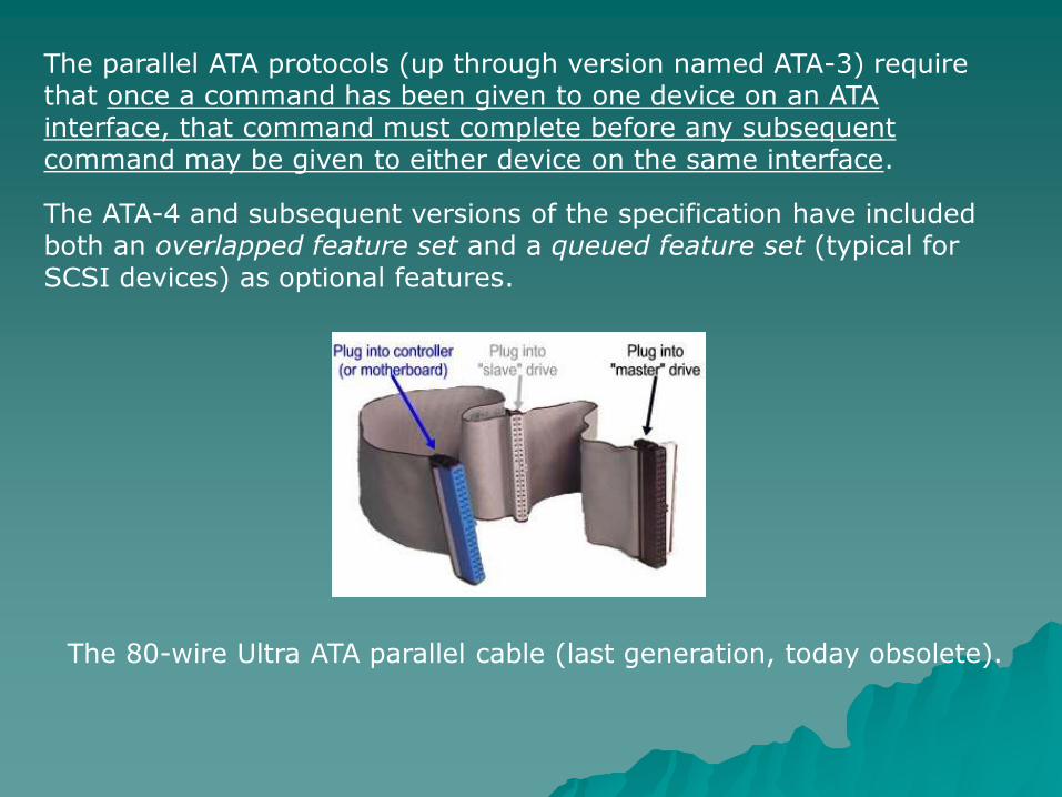
The parallel ATA protocols (up through version named ATA-3) require that once a command has been given to one device on an ATA interface, that command must complete before any subsequent command may be given to either device on the same interface.
The ATA-4 and subsequent versions of the specification have included both an overlapped feature set and a queued feature set (typical for SCSI devices) as optional features.
The 80-wire Ultra ATA parallel cable (last generation, today obsolete).
Pin 1 RESET Pin 11 DATA3 Pin 21 DDRQ Pin 31 IRQ
Pin 2 GND Pin 12 DATA12 Pin 22 GND Pin 32 N.C.
Pin 3 DATA7 Pin 13 DATA2 Pin 23 I/O Write Pin 33 ADDR1
Pin 4 DATA8 Pin 14 DATA13 Pin 24 GND Pin 34 DMA 66 Detect
Pin 5 DATA6 Pin 15 DATA1 Pin 25 I/O Read Pin 35 ADDR0
Pin 6 DATA9 Pin 16 DATA14 Pin 26 GND Pin 36 ADDR2
Pin 7 DATA5 Pin 17 DATA0 Pin 27 IOC HRDY Pin 37 CS 1P
Pin 8 DATA10 Pin 18 DATA15 Pin 28 Cable Select Pin 38 CS 3P
Pin 9 DATA4 Pin 19 GND Pin 29 DDACK Pin 39 Activity
Pin 10 DATA11 Pin 20 Key / Vcc (flash) Pin 30 GND Pin 40 GND
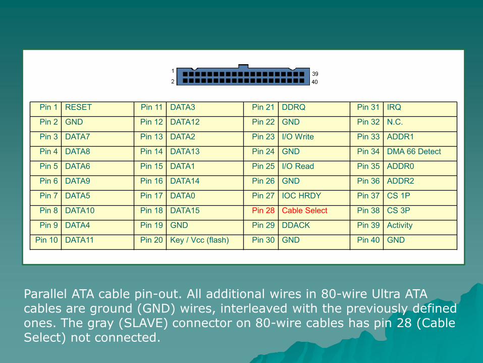
Parallel ATA cable pin-out. All additional wires in 80-wire Ultra ATA cables are ground (GND) wires, interleaved with the previously defined ones. The gray (SLAVE) connector on 80-wire cables has pin 28 (Cable Select) not connected.
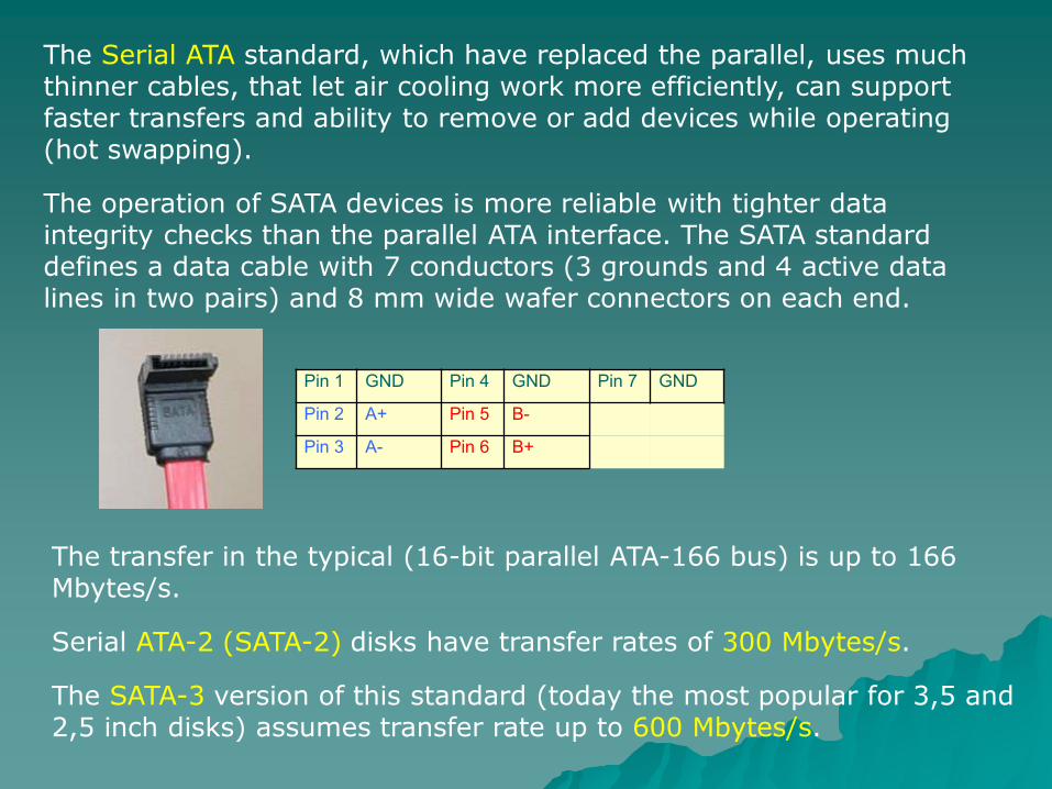
The Serial ATA standard, which have replaced the parallel, uses much thinner cables, that let air cooling work more efficiently, can support faster transfers and ability to remove or add devices while operating (hot swapping).
The operation of SATA devices is more reliable with tighter data integrity checks than the parallel ATA interface. The SATA standard defines a data cable with 7 conductors (3 grounds and 4 active data lines in two pairs) and 8 mm wide wafer connectors on each end.
Pin 1 GND Pin 4 GND Pin 7 GND
Pin 2 A+ Pin 5 B-
Pin 3 A- Pin 6 B+
The transfer in the typical (16-bit parallel ATA-166 bus) is up to 166 Mbytes/s.
Serial ATA-2 (SATA-2) disks have transfer rates of 300 Mbytes/s.
The SATA-3 version of this standard (today the most popular for 3,5 and 2,5 inch disks) assumes transfer rate up to 600 Mbytes/s.
1.3.4. SCSI interface.
The SCSI (Small Computer Systems Interface) is a standard, parallel bus (16 data lines) or serial bus (Serial Attached SCSI – SAS described by SCSI-3 standard) which can connect different devices for interchanging data between them independently.
Many devices can send and receive data simultaneously – the RAID array can send data to tape backup library without any actions performed by the computer, for example.
The SCSI host adapter, which organizes the traffic, can actually distinguish between 16 different devices using 4-bit hardware address set by jumpers (usually 7d = 0111b is the address of host adapter, so up to 15 other devices can be serviced by one adapter). Each device can be internally divided using different Logical Unit Names (LUNs). The cables can connect devices built inside the machine or mounted in external cases (there’s limit up to 12 m for external parallel SCSI cable length). It’s also possible to attach two computers to the one storage device (RAID array used by two different fileservers, for example).
The SCSI specification defines many different standards of cables and connectors, for external and internal use. Probably the last parallel cabling was Ultra 640 SCSI, newer solutions are based on serial electric and fibre-optic hardware interfaces.
The transfer in the typical (16-bit parallel Ultra 320 SCSI bus) was up to 320 Mbytes/s and 640 Mbytes/s for Ultra 640 parallel SCSI.
Serial Attached SCSI disks, using the same cables and connectors like SATA devices, had formely transfer rates of 300 Mbytes/s. The SAS-2 standard assumes the transfer rate 6 Gbit/s (about 750 Mbytes/s) and now is the most popular standard for 2,5 inch disk drives dedicated for disk arrays.
With the serial optical interfaces data rates 1, 2 and 4 Gbit/s were accessible in first implementations (about 500 Mbytes/s for 4 Gbit/s devices). The 8 Gbit/s and 10 Gbit/s optical buses are now typically in use.
1.4. Redundant disk arrays (RAID).
Redundant Array of Independent Drives (or Disks), also known as Redundant Array of Inexpensive Drives (or Disks), (RAID) is a general term for computer data storage schemes that divide and/or replicate data among multiple hard drives.
RAID can be designed to provide increased data reliability and/or increased I/O performance. A number of standard schemes have evolved which are referred to as levels. There were five RAID levels originally conceived, but many more variations have evolved, notably several nested levels and many non-standard levels.
RAID aggregates physical hard disks into a single logical unit either by using special hardware or software. Hardware solutions (RAID controllers) often are designed to present themselves to the attached system as a single hard drive, and the operating system is unaware of the technical workings. Software solutions are typically implemented in the operating system (like Linux, for example), and again would present the RAID drive or partition as a single drive or partition to applications.
Most commonly used RAID levels are:
RAID-0 – Striped set (aggregation of minimum 2 disks) without any parity checking. Provides improved performance and additional storage but no fault tolerance. Any disk failure destroys the entire array – due to lack of parity checking there’s no redundant information needed to restore lost data.
RAID-1 – Mirrored set (minimum 2 disks) without parity. Provides fault tolerance from disk errors and single disk failure. Increased read performance occurs when using a multi-threaded operating system that supports split seeks, very small performance reduction when writing. Array continues to operate so long as at least one drive is functioning. Replacement of the broken drive requires re-synchronization of the array.
RAID-3 (and RAID-4) – Configuration of minimum 3 disks where one disk is dedicated for recording parity checks to the rest of group. The single parity disk is a bottle-neck for writing since every write requires updating the parity data. One minor benefit is the dedicated parity disk allows the parity drive to fail and operation will continue without parity or performance penalty.
RAID-5 – Striped set (minimum 3 disks) with distributed parity checking information. Distributed parity requires all but one drive to be present to operate; drive failure requires replacement, but the array is not destroyed by a single drive failure. Upon drive failure, any subsequent reads can be calculated from the distributed parity such that the drive failure is masked from the end user. The array will have data loss in the event of a second drive failure and is vulnerable until the data that was on the failed drive is rebuilt onto a replacement drive.
RAID-6 – Striped set (minimum 4 disks) with dual distributed parity. Provides fault tolerance from two drive failures – array continues to operate with up to two failed drives. This makes larger RAID groups more practical, especially for high availability systems. As drives grow in size, they become more prone to error. This becomes increasingly important because large-capacity drives lengthen the time needed to recover (re-synchronization) from the failure of a single drive. Single parity RAID levels are not secured against data loss until the failed drive is rebuilt – the larger is the drive, the longer the rebuild will take. Dual parity gives time to rebuild the array by recreating a failed drive with the ability to sustain failure on another drive in the same array.
Many storage controllers allow RAID levels to be nested. That is, one RAID can use another RAID as its basic element, instead of using physical drives. It is instructive to think of these arrays as layered on top of each other, with physical drives at the bottom.
Nested RAIDs are usually signified by joining the numbers indicating the RAID levels into a single number, sometimes with a ”+” in between. For example, RAID 10 (or RAID 1+0) conceptually consists of multiple level 1 arrays stored on physical drives with a level 0 array on top, striped over the level 1 arrays. Given the large amount of custom configurations available with a RAID array, many companies, organizations, and groups have created their own non-standard configurations.
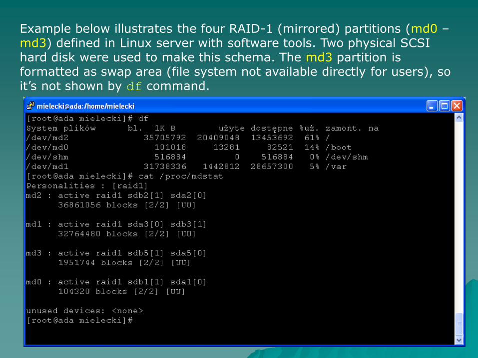
Example below illustrates the four RAID-1 (mirrored) partitions (md0 – md3) defined in Linux server with software tools. Two physical SCSI hard disk were used to make this schema. The md3 partition is formatted as swap area (file system not available directly for users), so it’s not shown by df command.
1.5. Advanced (enterprise-class) storage systems.
Mass storage attached directly to computer, like internal hard disk in laptop or internal RAID array in Small Office / Home Office (SoHo) class server, can be classified as Direct Attached Storage (DAS) type of mass memory. Of course it’s the simplest and cheapest way of implementing mass storage.
More advanced hardware platforms designed to gain much higher performance and flexibility (more than one computer using the same storage devices, for example) often use external storage systems, connected to servers with standard or dedicated network interfaces (more or less like network printers). We can distinguish between two kinds of ”networked” mass storage solutions:
Network Attached Storage (NAS) – the storage system is attached directly to local area network (LAN), using standard interface (Ethernet, for example) and standard network protocols (TCP/IP and some kind of upper-level protocol, like Server Message Block – SMB for example). The storage space should be available from each point in the network, regardless of operating system or network client software installed on particular computer.
Storage Area Network (SAN) – the storage system is implemented as dedicated network (separated from local network), with it’s own media (optical cables and switches in most of cases and hardware-level layer (optical network adapters). Term ”fabric” is in use for this kind of network infrastructure. The solutions widely in use today are based on optical cabling (10 Gbit/s for example) and SCSI logical organization (set of commands understandable for devices). Very popular solution is embedding SCSI protocol in the TCP/IP network protocol (SCSI over IP).
Most of today’s enterprise-class server installations utilize the SAN mass storage architecture. The hardware manufacturers are supplying families of devices (disk arrays, tape libraries optical network adapters and switches, even single hard disks with optical interfaces) to make building this kind of hardware platforms more and more flexible, scalable and economic.
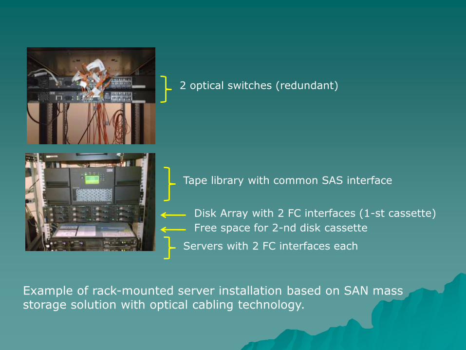
2 optical switches (redundant)
Tape library with common SAS interface
Servers with 2 FC interfaces each
Disk Array with 2 FC interfaces (1-st cassette)
Free space for 2-nd disk cassette
Example of rack-mounted server installation based on SAN mass storage solution with optical cabling technology.
2. General considerations about Input / Output devices.
The basic (primitive) I/O device used to implement more sophisticated interfaces (like ATAPI or SCSI, for example) is the single, parallel (8-bit, for example) register, which can be accessed both from the internal computer structure (i.e. by CPU) and from the outside world. This kind of register is called a parallel port. We can distinguish between ports of 2 types:
Input port, which can be read by the CPU using standard assembly-language instruction like IN <register>, <port_address>. The values of the bits in the input port are set by external device by appropriate electric circuits.
Output port, which can be written by the CPU using standard assembly-language instruction like OUT <port_address>, <register>. The external device (connected to the port by appropriate wires or other circuitry) can read the values set by CPU.
In many cases the same port (at the same address) can be used as an Input or Output both, or programmed as Input or Output before using (Intel 8255 chip, for example). The parallel standard interfaces uses mostly 2 or more 8-bit parallel ports to implement more or less sophisticated external bus with 8 or 16 data lines and set of control signals (inputs and outputs). One of the most well-known interfaces of this type is/was old-type parallel printer interface (Centronics). Also the interfaces designed for storage devices (described above) were previously implemented this way.
The main disadvantage of the parallel connections between the computer and external devices is the problem of crosstalk between the wires inside the connecting cable. High-frequency (50 MHz or more) electric signal in one wire can induct the interferences in the surrounding wires. This problem can be solved by shielding (separating the wires, inserting the grounded wire between each two signal wires), like it’s done in Ultra ATA parallel cables, for example. But the frequencies much higher than 100 MHz require even better separation (twisting the pairs of wires, like in Ultra 320 parallel SCSI cables. The cost of such a cable is much higher (about 50 $) than ”normal”, flat cable.
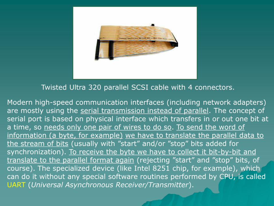
Twisted Ultra 320 parallel SCSI cable with 4 connectors.
Modern high-speed communication interfaces (including network adapters) are mostly using the serial transmission instead of parallel. The concept of serial port is based on physical interface which transfers in or out one bit at a time, so needs only one pair of wires to do so. To send the word of information (a byte, for example) we have to translate the parallel data to the stream of bits (usually with ”start” and/or ”stop” bits added for synchronization). To receive the byte we have to collect it bit-by-bit and translate to the parallel format again (rejecting ”start” and ”stop” bits, of course). The specialized device (like Intel 8251 chip, for example), which can do it without any special software routines performed by CPU, is called UART (Universal Asynchronous Receiver/Transmitter).
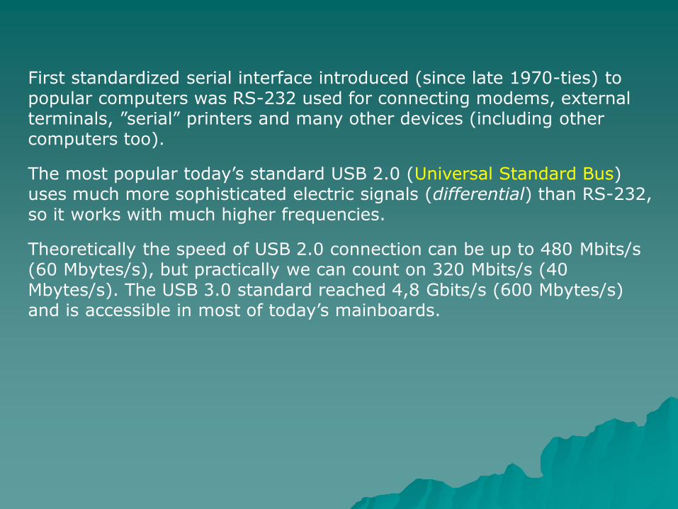
First standardized serial interface introduced (since late 1970-ties) to popular computers was RS-232 used for connecting modems, external terminals, ”serial” printers and many other devices (including other computers too).
The most popular today’s standard USB 2.0 (Universal Standard Bus) uses much more sophisticated electric signals (differential) than RS-232, so it works with much higher frequencies.
Theoretically the speed of USB 2.0 connection can be up to 480 Mbits/s (60 Mbytes/s), but practically we can count on 320 Mbits/s (40 Mbytes/s). The USB 3.0 standard reached 4,8 Gbits/s (600 Mbytes/s) and is accessible in most of today’s mainboards.
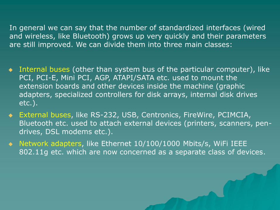
In general we can say that the number of standardized interfaces (wired and wireless, like Bluetooth) grows up very quickly and their parameters are still improved. We can divide them into three main classes:
Internal buses (other than system bus of the particular computer), like PCI, PCI-E, Mini PCI, AGP, ATAPI/SATA etc. used to mount the extension boards and other devices inside the machine (graphic adapters, specialized controllers for disk arrays, internal disk drives etc.).
External buses, like RS-232, USB, Centronics, FireWire, PCIMCIA, Bluetooth etc. used to attach external devices (printers, scanners, pen-drives, DSL modems etc.).
Network adapters, like Ethernet 10/100/1000 Mbits/s, WiFi IEEE 802.11g etc. which are now concerned as a separate class of devices.
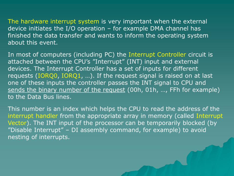
The hardware interrupt system is very important when the external device initiates the I/O operation – for example DMA channel has finished the data transfer and wants to inform the operating system about this event.
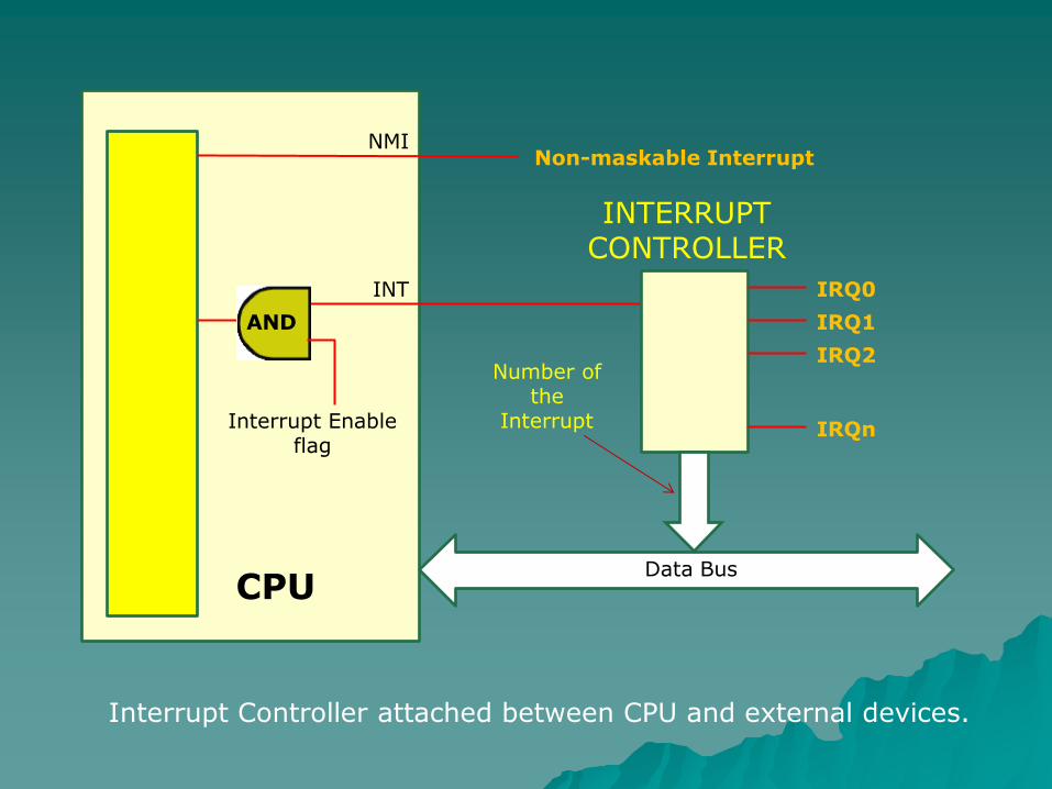
In most of computers (including PC) the Interrupt Controller circuit is attached between the CPU’s ”Interrupt” (INT) input and external devices. The Interrupt Controller has a set of inputs for different requests (IORQ0, IORQ1, …). If the request signal is raised on at last one of these inputs the controller passes the INT signal to CPU and sends the binary number of the request (00h, 01h, …, FFh for example) to the Data Bus lines.
This number is an index which helps the CPU to read the address of the interrupt handler from the appropriate array in memory (called Interrupt Vector). The INT input of the processor can be temporarily blocked (by ”Disable Interrupt” – DI assembly command, for example) to avoid nesting of interrupts.
Interrupt Enable flag
Non-maskable Interrupt
Data Bus
IRQ0
IRQ1
IRQ2
IRQn
CPU
NMI
INT
Number of the
Interrupt
INTERRUPT CONTROLLER
Interrupt Controller attached between CPU and external devices.
AND