Embed Size (px)
Citation preview

Introduction to Computer Engineering
ECE 203
Northwestern University
Department of Electrical Engineering and Computer Science
Teacher: Robert DickOffice: L477 TechEmail: [email protected]: 467–2298Webpage: http://www.ece.northwestern.edu/˜dickrp/ece203Teaching Assistants Zhenyu Gu (L470)
Debasish Das (M314)
1

Homework index
1 Assigned reading . . . . . . . . . . . . . . . . 54
2

Today’s topics
• Administrative
• Review: Build a multiplier
• Finite state machines
• Back to latches
• Debouncing
3

Multiplication
• Already went through this on the blackboard
• Wanted the class to do it together, also want you to have clear
lecture notes on it
• To understand why these trade-offs exist, we need to understand
the fundamentals of arithmetic circuits
• We have already discussed the selection of number systems and
the design of adders/subtracters
• Similar alternatives exist for multipliers
4
Multiplication
• Multiplication is the repeated application addition of ANDed bits
and shifting (multiplying by two)
• Multiplication is the sum of the products of each bit of one
operand with the other operand
• Consequence: A product has double the width of its operands
5

Multiplication
Recall that multiplying a number by two shifts it to the left one bit
6 ·3 = 6 · (22 ·0+21 ·1+20 ·1)
= 6 ·22 ·0+6 ·21 ·1+6 ·20 ·1
110 ·011 = 11000 ·0+1100 ·1+110 ·1
= 110+1100
= 10010
= 18
6
Multiplication
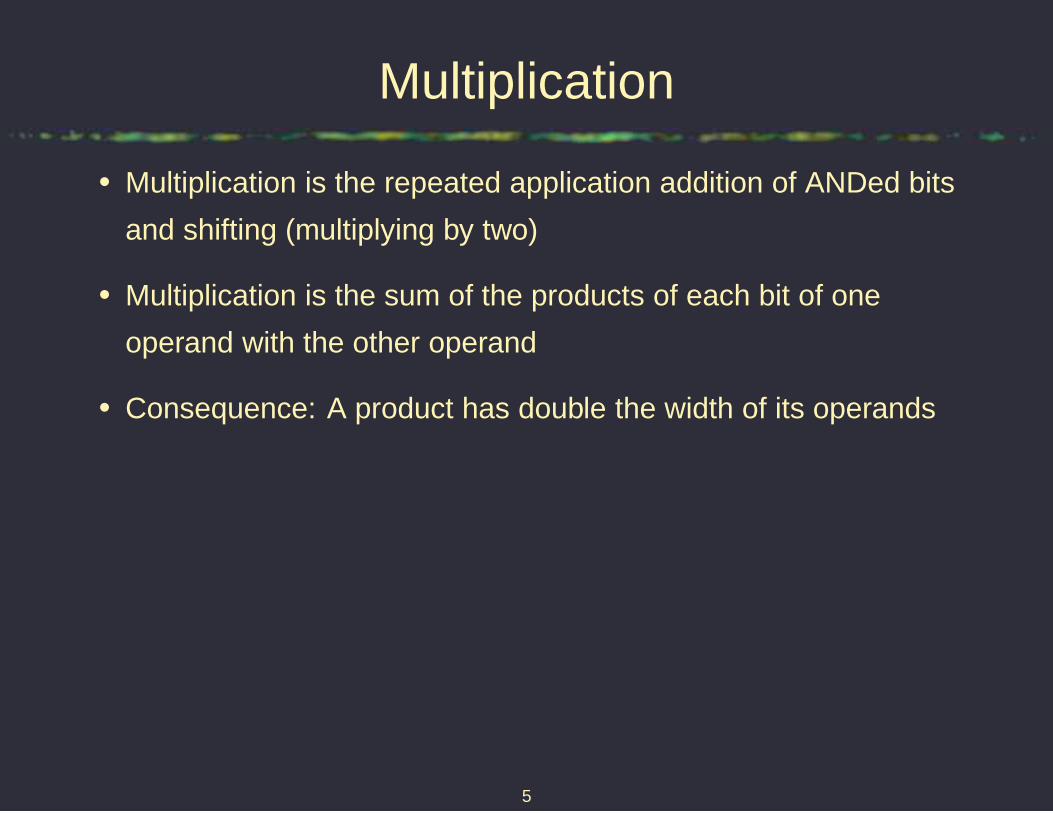
A2 A1 A0
× B2 B1 B0
A2B0 A1B0 A0B0
A2B1 A1B1 A0B1
+ A2B2 A1B2 A0B2
sum5 sum4 sum3 sum2 sum1 sum0
7

Multiplication
Consider multiplying 6 (110) by 3 (011)
1 1 0
× 0 1 1
1 1 0
1 1 0
+ 0 0 0
0 1 0 0 1 0
8

Multiplier implementation
• Direct implementation of this scheme possible
• Partial products formed with ANDs
• For four bits, 12 adders and 16 gates to form the partial products
– 88 gates
• Note that the maximum height (number of added bits) is equal to
the operand width
9

Combinational multiplier
A 0 B 0 A 1 B 0 A 0 B 1 A 0 B 2 A 1 B 1 A 2 B 0 A 0 B 3 A 1 B 2 A 2 B 1 A 3 B 0 A 1 B 3 A 2 B 2 A 3 B 1 A 2 B 3 A 3 B 2 A 3 B 3
HA
S 0 S 1
HA
F A
F A
S 3
F A
F A
S 4
HA
F A
S 2
F A
F A
S 5
F A
S 6
HA
S 7
10
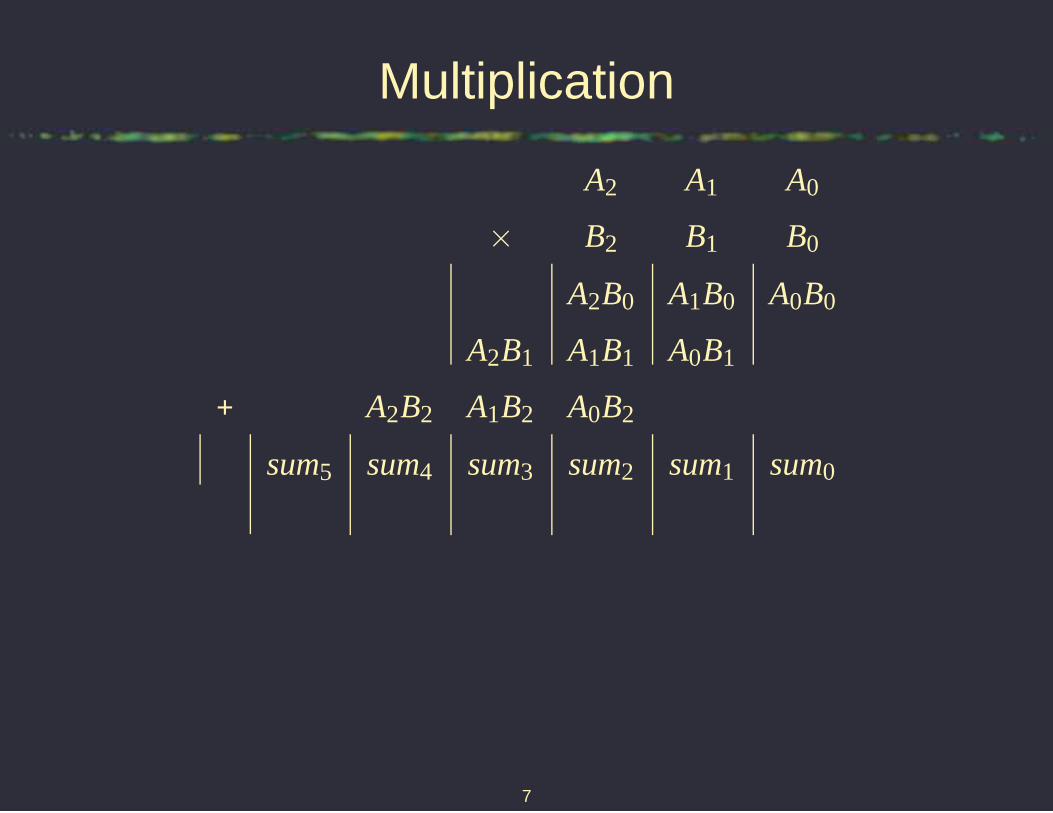
Multiplier building block
F A
X
Y
A B
S CI CO
Cin Sum In
Sum Out Cout
11

Combinational multiplier
C
C
C
P0
P1
P2P3P4P5
S
S
SSS
A2 B0 A1 B0 A0 B0
A0 B1A1 B1A2 B1
A1 B2 A0 B2A2 B2
12

Sequential multiplier
• Can iteratively one row of adders to carry out multiplications
• Advantage: Area reduced to approximately its square root
• Disadvantage: Takes n clock cycles, where n is the operand bit
width
13

2X2 sequential multiplier
co co coco ci ci cicisum sum sumsum
b b bb a a aa
Q QD D
QQQQ
Q Q Q
DDDD
D D D
clkclk
clk
clkclk
clk
clkclkclk
0
0
0
0
Operands already in registersAdder flip-flops cleared
14

2X2 sequential multiplier
co co coco ci ci cicisum sum sumsum
b b bb a a aa
Q QD DOperands
QQQQ
Q Q Q
DDDD
D D D
clkclk
clk
clkclk
clk
clkclkclk
0
0
0
0
Operands already in registersAdder flip-flops cleared
15

2X2 sequential multiplier
co co coco ci ci cicisum sum sumsum
b b bb a a aa
Q QD DOperands
Could be HA
Could be HA
QQQQ
Q Q Q
DDDD
D D D
clkclk
clk
clkclk
clk
clkclkclk
0
0
0
0
Operands already in registersAdder flip-flops cleared
16

Arithmetic/logic units
• Possible to implement functional units that can carry out many
arithmetic and logic operations with little additional area or delay
overhead
• Already saw example: Combined adder/subtracter
• Other operations possible
• Could you generalize the approach used for two’s complement
addition and subtraction to another pair of operations?
17
Arithmetic/logic operations
• Increment
• Addition
• Negation
• Subtraction
• Multiplication
– Slow or large
• Division
– Slow or large
18

Arithmetic/logic operations
• Shift left
– Fast, multiplication by two
• Shift right
– Fast, division by two
• Bit-wise operations
– AND, OR, NOT, NAND, NOR, XOR, and XNOR
19

Word description to state diagram
• Design a vending machine controller that will release (output
signal r) an apple as soon as 30¢ have been inserted
• The machine’s sensors will clock your controller when an event
occurs. The machine accepts only dimes (input signal d) and
quarters (input signal q) and does not give change
• When an apple is removed from the open machine, it indicates
this by clocking the controller with an input of d
• The sensors use only a single bit to communicate with the
controller
20

Word description to state diagram
• We can enumerate the inputs on which an apple should be
released
ddd +ddq+dq+qd +qq
d(dd +dq+q)+q(d +q)
d(d(d +q)+q)+q(d +q)
For d, i = 0, for q, i = 1
0(0(0+1)+1)+1(0+1)
21

Word description to state diagram
10
0
1
0
1
0
0
1
0(0(0 + 1) + 1) + 1(0 + 1)
1
A/0
B/0
C/0
D/1
E/0
22

Word description to state diagram
0
0
1
X
0(0(0 + 1) + 1) + 1(0 + 1)
X
1
X
A/0
B/0
C/0
D/1
E/0
23

State diagram to state table
nextcurrent state output (r)state i=0 i=1
A B E 0
B C D 0
C D D 0
D A A 1
E D D 0
24

Moore block diagram
combinational logic
sequential elements
combinational logic
feedback
inputs
outputs
25

Mealy block diagram
combinational logic
sequential elements
outputs
inputs
feedback
26

Moore FSMs
0
0
1
1
1
00 1
D/1
A/0 B/0
C/0
27

Mealy FSMs
1/X
1/0
0/00/0
0/1
1/0
1/10/1
CD
BA
28

Mealy tabular form
s+/q
s 0 1
A D/0 B/X
B C/1 B/0
C A/0 B/1
D C/1 C/0
29

FSM design summary
• Specify requirements in natural form
• Manually derive state diagram
– Automatic way to go from English to FSM, however more
theory required
– Can minimize state count, however, more theory also required
– See me if you want more information on this, or take a
compilers course and a graduate-level switching theory
course, or take my ECE 303
• Assign values to states to minimize logic complexity
• Optimize implementation of state and output functions
30
Back to latches
• Latches: Level sensitive
• Flip-flops: Edge-triggered
31

Review: Clocking conventions
Active-high transparent Active-low transparent
Positive (rising) edge Negative (falling) edge
DD
D D
Q Q
CLK CLK
CLK CLK
32

Latch and flip-flop equations
RS
Q+ = S+ R Q
D
Q+ = D
33

Latch and flip-flop equations
JK
Q+ = J Q + K Q
T
Q+ = T ⊕Q
34

JK latch
R−S latch
replacements
K
J S
RQ
Q
Use output feedback to ensure that RS 6= 11
Q+ = Q K + Q J
35

JK latch
J K Q Q+
0 0 0 0
0 0 1 1 hold
0 1 0 0
0 1 1 0 reset
1 0 0 1
1 0 1 1 set
1 1 0 1
1 1 1 0 toggle
36

JK race
100 Set Reset Toggle
Race Cond i t ion
J
K
Q
Q
37

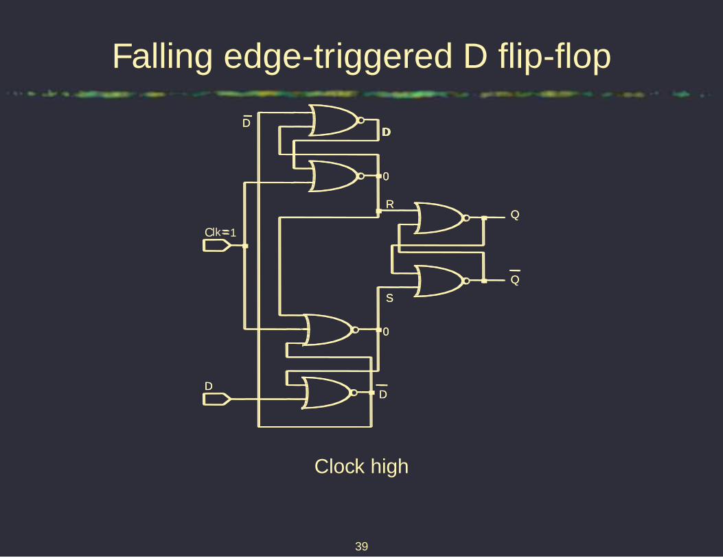
Falling edge-triggered D flip-flop
• Use two stages of latches
• When clock is high
– First stage samples input w.o. changing second stage
– Second stage holds value
• When clock goes low
– First stage holds value and sets or resets second stage
– Second stage transmits first stage
• Q+ = D
• One of the most commonly used flip-flops
38
Falling edge-triggered D flip-flop
DD
lk=
RR
SS
00
00
DD
DDDD
=1
DD
C
Clock high
39

Falling edge-triggered D flip-flop
Holds D whenclock goes low
Holds D whenclock goes low
Q
Q
DD
Clk=1
RR
SS
00
00
DD
DDDD
=
DD
Clock switching
Inputs sampled on falling edge, outputs change after falling edge
40

Falling edge-triggered D flip-flop
?
Clk=
RR
SS
D
0
DDDD
=
RR
SS
DD
0
D
Clock low
41

Another view of an edge-triggered DFF
Q
D
clkR
R
R
Q
Q
Q
Q
Q
Q
S
S
S
42

Edge triggered timing
Positive edge− t riggered FF
Negative edge− t riggered FF
100
D
CLK
Qpos
Qpos
Qneg
Qneg
43

RS clocked latch
• Storage element in narrow width clocked systems
• Dangerous
• Fundamental building block of many flip-flop types
44

JK flip-flop
• Versatile building block
• Building block for D and T flip-flops
• Has two inputs resulting in increased wiring complexity
• Edge-triggered varieties exist
45

D flip-flop
• Minimizes input wiring
• Simple to use
• Common choice for basic memory elements in sequential circuits
46

Debouncing
• Mechanical switches bounce!
• What happens if multiple pulses?
– Mutliple state transitions
• Need to clean up signal
47

Schmitt triggers
A B
A
Low
High
48

Schmitt triggers
A B
AVT L
VT H
Low
High
49
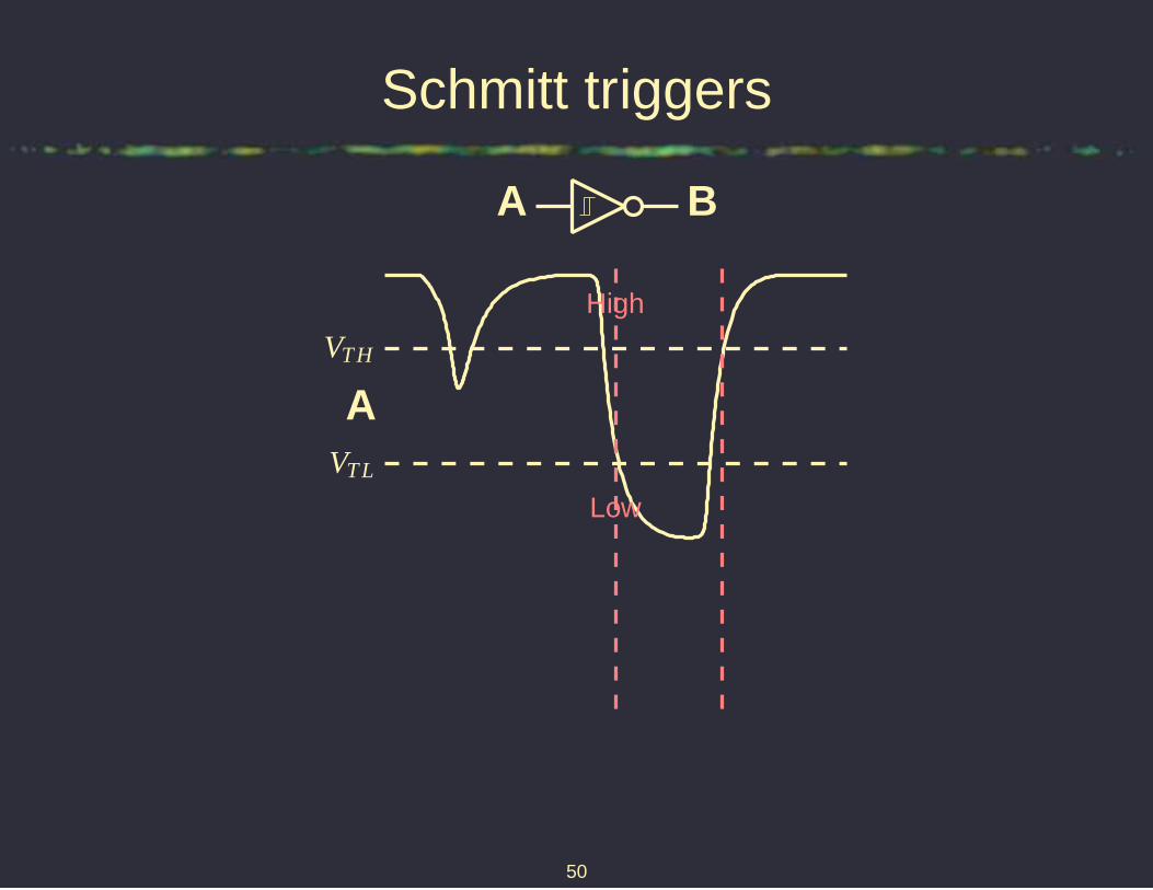
Schmitt triggers
A B
AVT L
VT H
Low
High
50

Schmitt triggers
transition
A B
AVT L
VT H
Low
High
51

Schmitt triggers
transitionB
A B
AVT L
VT H
Low
High
52

Debouncing
0
1
2
3
4
5
-1.0e-03 -5.0e-04 0.0e+00 5.0e-04 1.0e-03 1.5e-03
V
T (s)
Schmidt trig.RC
0.751.65
53
Assigned reading
• M. M. Mano and C. R. Kime, Logic and Computer Design
Fundamentals. Prentice-Hall, Englewood Cliffs, NJ, third ed.,
2004
• Review Sections 6.4 and 6.5
– If FSMs don’t make sense now, please ask questions, or see
me
– FSMs are tricky at first – Almost everybody has this moment
of epiphany at which they suddenly make sense
• Section 6.6
54

Computer geek culture references
• Parsers and lexical analyzers
• Writing problem-specific languages
• A. Aho, R. Sethi, and J. Ullman, Compilers principles, techniques,
and tools. Addison-Wesley, Reading, MA, 1986
• Lex and yacc
• Flex and bison
55