Embed Size (px)
Citation preview

•10/30/2015
•1
1
Introduction to CIM
Acknowledgment: These slides were downloaded from CIM user group web site at http://cimug.ucaiug.org/. They are authored by Xtensible Solutions, with modifications for being used in class.
2
Presentation Contents
• Background
• What is the CIM
• How the CIM is used in the Utility Enterprise– As a semantic model for information exchange
• Three Layer Architecture for Using the CIM Standards
• CIM UML model
• Profiles for business context
• Implementation syntax– XML Schema – for messaging
– RDF Schema - for model exchange
• Where to get CIM information

•10/30/2015
•2
3
CIM History
• 1992 – Unified Information turned over a data model based on the EPRI OTS to the CCAPI Task Force with the understanding it would be turned into an industry standard model
• 1993 to 1996 - The CCAPI task force expanded the data model with a primary goal of enabling use of plug compatible applications to help protect utility investment in applications
– Entity Relationship Visio Diagram with MS Access database
• 1996 – The CIM was turned over to IEC Technical Committee 57, Working Group 13&14, where it is advancing through the standards process. It covers both electric utility transmission and distribution business operations
– Converted to UML and initially maintained in Rational Rose • 2000 – NERC mandates CIM and first IOP test• 2003 – ISO/RTO Council and EPRI sponsored an initiative to expand CIM
into Market Operations, a.k.a. CME, followed by extensions for Planning and Dynamics
• 2005 – First edition of IEC 61970-301 CIM Base• 2005 – CIM Users Group established under UCA Users Group• 2008 – CIM adopted by UCTE• 2009 – NIST identifies CIM as key standard for Smart Grid interoperability• 2010 – ENTSO-E migrates to CIM and holds first IOP test
4
The IEC Common Information Model (CIM) - What Is It?• A set of standards in enable system integration and information exchange
based on a common information model– Provides a general information model and message/file schemas for
messages/files exchanged between systems
• A key differentiator: The CIM standards are based on a Unified Modeling Language (UML) based information model representing real-world objects and information entities exchanged within the value chain of the electric power industry
– Provides common semantics for all information exchanges• Referred to as Model-Driven Integration (MDI)
– Not tied to a particular application’s view of the world• But permits same model to be used by all applications to facilitate information sharing
between applications
– Maintained by IEC in Sparx Enterprise Architect modeling tools
– Many tools available generating design artifacts and documentation
– Enable data access to enterprise data warehouse in a standard way

•10/30/2015
•3
5
GridWise Interoperability Framework
Role of CIM
6
Sample Power System Model
Generator AC Line Substation
Company
Load
Operates
Operates
Belongs To
Member Of
Owns
Load Area
Connects To
Connects To
Connects To
•10/30/2015
•4
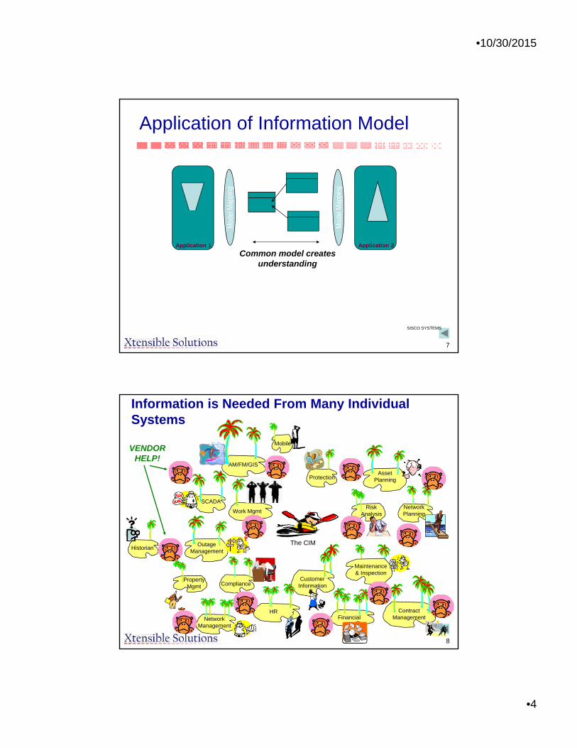
7
Application of Information Model
SISCO SYSTEMS
Common model creates understanding
Application 1 Application 2
8
Information is Needed From Many Individual Systems
AM/FM/GIS
Mobile
SCADA
Work Mgmt
CustomerInformation
NetworkManagement
Maintenance& Inspection
HRFinancial
ContractManagement
ProtectionAsset
Planning
RiskAnalysis
NetworkPlanning
HistorianOutage
Management
PropertyMgmt Compliance
The CIM
VENDORHELP!

•10/30/2015
•5
9
The Common Language Should Provide Relevant Information To A User Regardless of Source
EngineeringConcerns
MaterialsManagement
ConcernsConstruction
Concerns
OperationsConcerns
ProtectionConcerns
MaintenanceConcerns
10
The Needs of Various Users –Some Same, Some Different
Engineering Concerns The logical view of how the type of equipment fits (will fit) in the electrical network. Nominal configuration of “as-built” and “future” states. Field Name Spatial Location Version Physical Connectivity Load Projections Capacity Requirements Compatible Unit Equipment Ratings
Construction Concerns Lifecycle information regarding when and how to install equipment: Field Name Location Equipment Manufacturer/Model Compatible Unit Equipment Ratings Work Order Work Design Installation Schedule &Budget Permits Manufacturer Specifications Safety Requirements
Materials Management Concerns Planning and tracking material requirements for construction and maintenance. Information about physical pieces of equipment. Asset Identifier Compatible Unit Equipment Component Type Equipment Manufacturer/Model Serial Number Location Equipment Location History Manufacturer Specifications

•10/30/2015
•6
11
The Needs of Various Users –Some Same, Some Different (continued)
Operations Concerns Real-time condition of equipment and electrical network necessary to maintain reliable network operation: Field Name Schematics & Spatial Location Electrical Connectivity Operational Limits (dynamic) Equipment Status Clearances Network Measurements (voltage,
current, frequency) Equipment Faults Weather Measurements Operational Restrictions
Maintenance Concerns Lifecycle information regarding when and how equipment is maintained: Field Name Location Equipment Manufacturer/Model Equipment Ratings Routine Maintenance Testing & Diagnostics
Procedures Equipment Condition Inspection Schedule Equipment Repair Records Site Service Records Maintenance Budget Safety Requirements
Protection Concerns Setting and configuring relays based on equipment and network protection requirements: Field Name Schematics Electrical Connectivity Maximum Capacity Zones Of Protection Equipment Status Clearances Network Measurements
(voltage, current, frequency, transients)
Equipment Faults
12
Exchanging Common Language Messages Among Systems Should Provide Relevant Information To Each System That Is Harmonious With All Other Systems’ Information
WorkBlah, Blah, Blah,
Organization,Blah, Blah, Blah
MaintenanceBlah, Blah, Blah,
Organization,Blah, Blah, Blah Switching Schedule
Blah, Blah, Blah, Organization,
Blah, Blah, Blah
Load Data SetBlah, Blah, Blah,
Organization,Blah, Blah, Blah
Meter ReadingBlah, Blah, Blah,
Organization,Blah, Blah, Blah
Load ControlBlah, Blah, Blah,
Organization,Blah, Blah, Blah
Asset CatalogBlah, Blah, Blah,
Organization,Blah, Blah, Blah
CrewBlah, Blah, Blah,
Organization,Blah, Blah, Blah
Service ConnectionRequest
Blah, Blah, Blah, Organization,
Blah, Blah, Blah
Planned OutageBlah, Blah, Blah,
Organization,Blah, Blah, Blah
For example, in each of the message exchanges depicted above, the same Organization is referenced for different reasons. There should be NO inconsistencies about this Organization in them!

•10/30/2015
•7
13
For example, a common language-based logical infrastructure facilitates collaboration among the many applications involved in Asset Management
Asset Strategy
Asset Portfolios
Risk Management
RegulatoryReporting
Financial Management
ResourceScheduling &
Planning
Equip./FleetManagement
Supply Chain Management
ContractManagement
Mobile Workforce
Mgmt.
Work Collaboration & Reporting
Work Design
Asset Owner Asset Manager Service Provider
Asset Investment Planning Asset Program Management
Customer Management Asset Operations
CIS
CRM
IVR eBusiness EMS DMS
SCADA
OMS
Asset Planning Tool
Budget Load Forecast
ReliabilityAnalysis
NetworkAnalysis
Asset Repository
ExecutiveDashboard
Program Mgmt.
Work Mgmt.
Mobile & Dispatching
Contract Mgmt.
GISRevenue
Facility I&M
Portal
SA/DA
Metering
SRCM
[source: DistribuTECH 2003 paper by Zhou & Robinson]
14
Application To Common Language Mapping –The Typical Field to Field Process Is Cumbersome
• Individual fields of data models from data sources are mapped to each other
• Approach does not scale well as the number of maps grows exponentially with each new data source
• Mapping is a challenge as ‘mappers’ must have an in depth understanding of all relevant data sources – a tall order!

•10/30/2015
•8
15
Using A Semantic Model ToSimplify & Scale Up The Mapping Process
• What is a Semantic Model?– The key ingredients that make up a semantic model are a vocabulary of
basic terms, a precise specification of what those terms mean and how they relate to each other.
• How is it used?– Before making mappings, a model (or an ontology) of a given business
domain is defined. – The model is expressed in a knowledge representation language and it
contains business concepts, relationships between them and a set of rules.
– By organizing knowledge in a discrete layer for use by information systems, semantic models enable communication between computer systems in a way that is independent of the individual system technologies, information architectures and applications.
– Compared to one-to-one mappings, mapping data sources to a common semantic model offer a much more scaleable and maintainable way to manage and integrate enterprise data.
[source: TopQuadrant Technology Briefing, July 2003]
16
ETLIntegration BusWeb Services
Apps.
GenericServices
Composite Applications
DW
Business Intelligence
CommonLanguage
SemanticModel
Metadata
The CIM Provides a Semantic Layer in an Enterprise Architecture
•10/30/2015
•9
17
App CIMY.1 X.1Y.2 X.2Y.3 X.3Y.4 X.4Y.5 X.5
Publisher
Publishers:One Application Connector:•Obtains Data From Application And/Or Database•Transforms Data (if necessary) to the “CommonLanguage” (a Canonical Data Model)
•Puts Data Into Message Template•Publishes The Message (Fires & Forgets)
DataWarehouse
SubstationAutomation
OMS
DistWiresModel
GridWiresModel
DAC
CIS
VRU
AM/FM/GIS
DistributionAutomation
HumanResources
OutageReporting
Event History WorkManagement
EMS
...
CIMX.1 X.2 X.3 X.4 X.5
Subscriber
CIM AppX.1 B.1X.2 B.2X.3 X.4 X.5
Subscriber
CIM AppX.1 A.1X.2 X.3 X.4 A.4X.5 A.5
Subscriber
CIM AppX.1 C.1X.2 X.3 C.3X.4 C.4X.5
Subscriber
Subscribers:Several Application Adapters Receive The Same MessageEach Adapter:•Parses Message, Pulling Out Data Needed By Application•Transforms Data (if necessary) to Local Application Format•Passes Data To Local Application And/Or Database Through Most Appropriate Means
Message Type Instance: ChangedNetworkDataSet (Expressed In Common Language)
Decoupled InformationExchange
2003-2004 Xtensible Solutions, Inc. 17
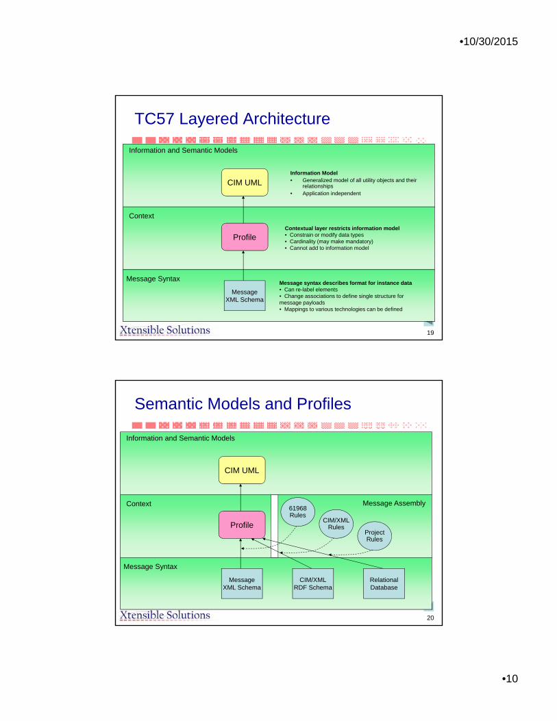
18
The CIM and Related Standards
• But the CIM standards are more than just an abstract information model expressed in UML
• Profiles for specifying a subset of the CIM classes and attributes for a specific business context at a specific system interface or system interaction
• Implementation models– Use of XML to create serialized files and messages
• RDF Schema-based standards for power system model exchange
• XML Schema-based standards for information message payloads
– ETL based on CIM for data base access• DDLs for data tables
•10/30/2015
•10
19
TC57 Layered Architecture
CIM UML
Information and Semantic Models
Context
Message Syntax
Profile
MessageXML Schema
Contextual layer restricts information model• Constrain or modify data types• Cardinality (may make mandatory)• Cannot add to information model
Message syntax describes format for instance data• Can re-label elements• Change associations to define single structure for message payloads• Mappings to various technologies can be defined
Information Model• Generalized model of all utility objects and their
relationships• Application independent
20
Semantic Models and Profiles
CIM UML
Information and Semantic Models
Context
Message Syntax
Profile
MessageXML Schema
CIM/XMLRDF Schema
RelationalDatabase
61968Rules
CIM/XMLRules
ProjectRules
Message Assembly

•10/30/2015
•11
21
To Summarize
• The CIM is an abstract information modelstandard expressed in UML.
• Profiles specifying a subset of the CIM classes and attributes for specific business context
• Implementation technologies, such as use of XML to create serialized files and messages– Standards for power system models– Standards for information message payloads
• Also, the CIM UML can be extended– Standard extensions for new functional areas– Private extensions for specific utility requirements
22
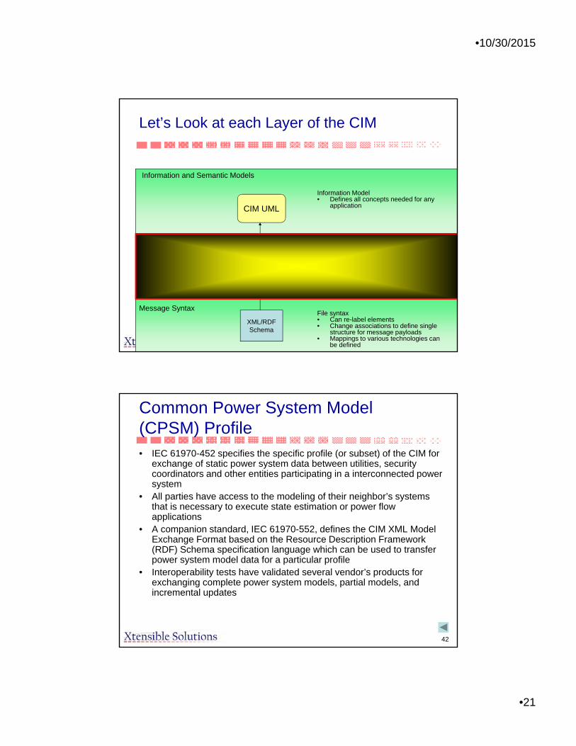
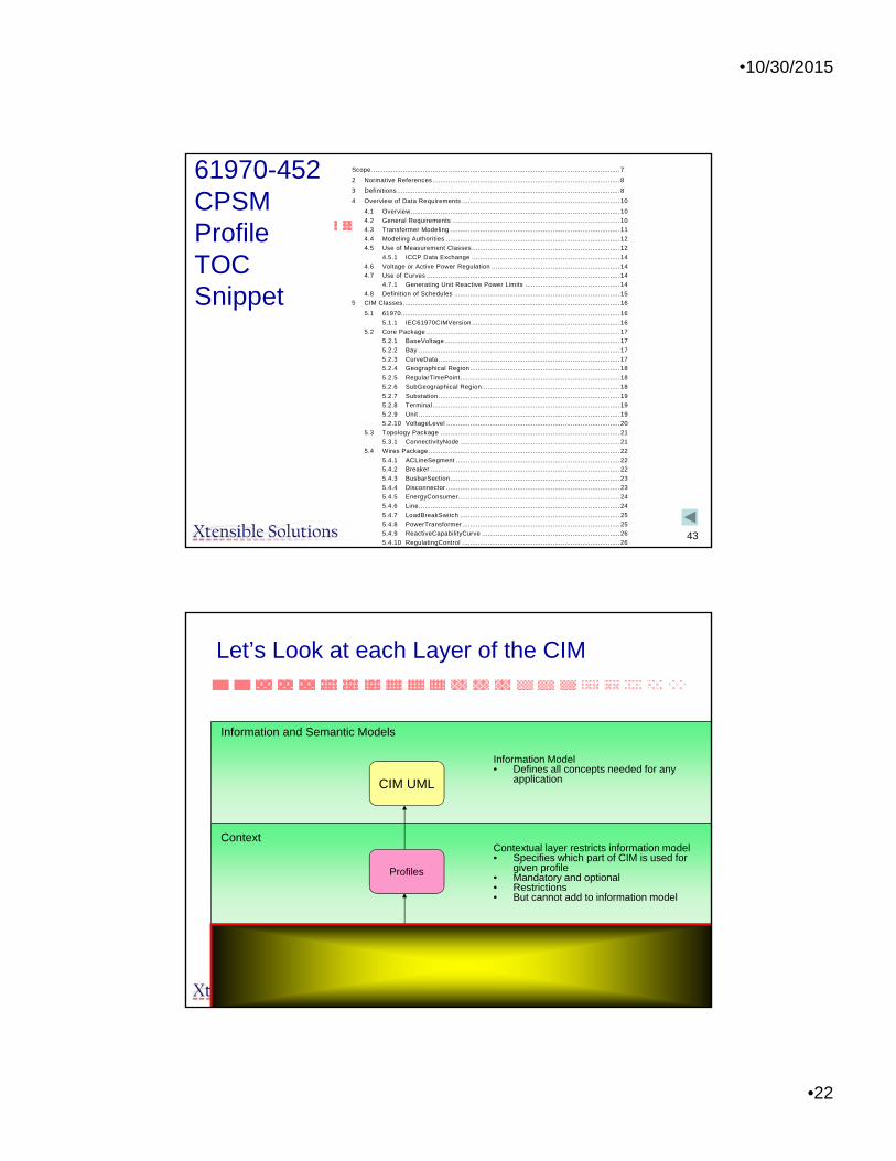
Let’s Look at each Layer of the CIM
CIM UML
Information and Semantic Models
Context
Message Syntax
Profiles
XML/RDFSchema
Information Model• Defines all concepts needed for any
application
Contextual layer restricts information model• Specifies which part of CIM is used for
given profile• Mandatory and optional• Restrictions• But cannot add to information model
File syntax• Can re-label elements• Change associations to define single
structure for message payloads• Mappings to various technologies can
be defined
•10/30/2015
•12
23
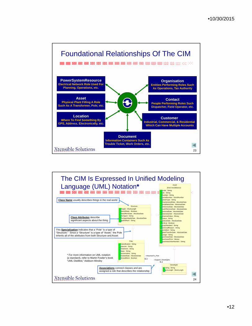
Foundational Relationships Of The CIM
PowerSystemResourceElectrical Network Role Used For
Planning, Operations, etc.
AssetPhysical Plant Filling A Role
Such As A Transformer, Pole, etc.
LocationWhere To Find Something By
GPS, Address, Electronically, etc.
OrganisationEntities Performing Roles Such
As Operations, Tax Authority
ContactPeople Performing Roles SuchDispatcher, Field Operator, etc.
DocumentInformation Containers Such AsTrouble Ticket, Work Orders, etc.
CustomerIndustrial, Commercial, & Residential
Which Can Have Multiple Accounts
24
Structure
height : ShortLength
weedAbate : Boolean
weedRemDate : AbsoluteDate
fumigant : String
fumigantApplyDate : AbsoluteDate
jpaRefNum : String
Asset
code : String
utc : String
number : String
serialNumber : SerialNumber
assetType : String
maufacturedDate : AbsoluteDate
installationDate : AbsoluteDate
inServiceDate : AbsoluteDate
outOfServiceDate : AbsoluteDate
removalDate : AbsoluteDate
warrantyDate : AbsoluteDate
financialValue : Money
status : String
statusDate : AbsoluteDate
critical : Boolean
corpStandard : String
removalReason : Stringcondition : String
plantTransferDate : AbsoluteDate
usage : StringpurchaseDate : AbsoluteDate
purchasePrice : Money
purchaseOrderNumber : String
(from AssetBasics)
Pole
classification : String
species : String
treatment : String
base : String
preservative : String
treatedDate : AbsoluteDate
breastBlock : Boolean
Streetlight
rating : String
armLength : ShortLength
0..1
0..n
+AttachedTo_Pole
0..1+Support_Streetlights
0..n
The CIM Is Expressed In Unified Modeling Language (UML) Notation*
Class Name usually describes things in the real world
Associations connect classes and areassigned a role that describes the relationship
Class Attributes describesignificant aspects about the thing
This Specialization indicates that a “Pole” is a type of“Structure.” Since a “Structure” is a type of “Asset,” the Poleinherits all of the attributes from both Structure and Asset
* For more information on UML notation (a standard), refer to Martin Fowler’s book“UML Distilled,” Addison-Wesley
•10/30/2015
•13
25
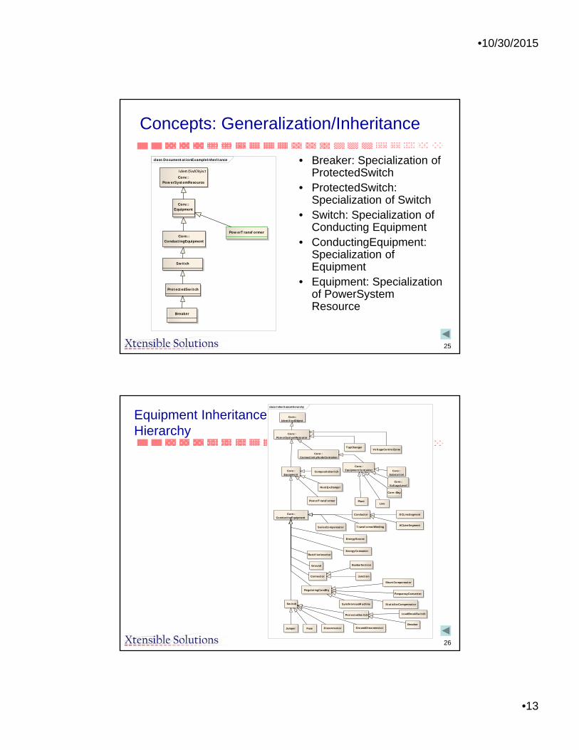
Concepts: Generalization/Inheritance
• Breaker: Specialization of ProtectedSwitch
• ProtectedSwitch: Specialization of Switch
• Switch: Specialization of Conducting Equipment
• ConductingEquipment: Specialization of Equipment
• Equipment: Specialization of PowerSystem Resource
class DocumentationExampleInheritance
IdentifiedObject
Core: :PowerSystemResource
Core: :Equipment
Core: :ConductingEquipment
Breaker
ProtectedSwitch
PowerTransf ormer
Switch
26
Equipment InheritanceHierarchy
class InheritanceHierarchy
Transf ormerWinding
Core: :PowerSystemResource
HeatExchanger
BusbarSection
VoltageControlZone
ShuntCompensator
ACLineSegment
DCLineSegment
LoadBreakSwitch
Core: :VoltageLevel
TapChanger
PowerTransf ormer
Fuse
StaticVarCompensator
RegulatingCondEq
Rectif ierInverter
Junction
Jumper
Ground
Conductor
Disconnector
EnergySource
SeriesCompensator
ProtectedSwitch
Core: :Identif iedObject
PlantLine
FrequencyConverter
Connector
Core: :Bay
Switch
Core: :ConnectivityNodeContainer
Core: :Substation
EnergyConsumer
GroundDisconnector
Core: :ConductingEquipment
Breaker
SynchronousM achine
Core: :Equipment
Core: :EquipmentContainer
CompositeSwitch

•10/30/2015
•14
27
NamingHierarchy 1
class NamingHierarchyPart1
Core: :Substation
Core: :Bay
Core: :VoltageLevel
Core: :SubGeographicalRegion
Line
Core: :GeographicalRegion
Core: : Identif iedObject
+ aliasName: String [0..1]+ description: String [0..1]+ localName: String [0..1]+ mRID: String [0..1]+ name: String [0..1]+ pathName: String [0..1]
Core: :Equipment
Core: :EquipmentContainer
Core: :PowerSystemResource
Plant
Core: :ConnectivityNodeContainer
+EquipmentContainer0..1
+Equipments0..*
+Region 0..1
+Regions 0..*
+Region 0..1
+Substations 0..*
+Region
0..1
+Lines 0..*
+VoltageLev el0..1
+Bay s0..*
+Bay s 0..*
+Substation
0..1
+Substation 1
+VoltageLev els 0..*
28
NamingHierarchy 2
class NamingHierarchyPart2
Fuse
EnergyConsumer
ShuntCompensator
Connector
BusbarSection
Breaker
ACLineSegment
Disconnector
Jumper
FrequencyConverter
EnergySource
StaticVarCompensator
Rectif ierInverter
Conductor
Core: :ConductingEquipment
Core: :Equipment
DCLineSegment
SynchronousM achine
CompositeSwitch
Switch
M eas: :M easurement
Core: :PowerSystemResource
Transf ormerWinding
TapChanger
PowerTransf ormer
Ground
RegulatingCondEq
GroundDisconnector
Production: : GeneratingUnit
Core: : Identif iedObject
+ aliasName: String [0..1]+ description: String [0..1]+ localName: String [0..1]+ mRID: String [0..1]+ name: String [0..1]+ pathName: String [0..1]
SeriesCompensator
ProtectedSwitch
LoadBreakSwitch
Junction
HeatExchanger
+PowerSy stemResource
0..1
+Measurements
0..*
+TransformerWindings 1..*
+PowerTransformer 1
+GeneratingUnit 0..1+Sy nchronousMachines 1..*
+HeatExchanger 0..1
+PowerTransformer 1
+CompositeSwitch 0..1
+Switches 0..*

•10/30/2015
•15
29
ConnectivityandTopology Model
class M ain
Core: :EquipmentContainer
Switch/Node static Model
ConnectivityNode
Core: :ConnectivityNodeContainer
Core: :Terminal
Bus/Branch calculated Model
TopologicalNode
M eas: :M easurement
Core: :ConductingEquipment
TopologicalIsland
Core: :PowerSystemResource
Core: :Identif iedObject
BusNameM arker
Core: :Equipment
Bus/Branch bus naming specificaitonstatic model.
ControlArea: :ControlArea
+ netInterchange: Activ ePower+ pTolerance: Activ ePower+ ty pe: ControlAreaTy peKind
+Terminals
0..*+ConductingEquipment
1
+TopologicalNode
0..*
+ControlArea0..1
+AngleRef_TopologicalIsland0..1
+AngleRef_TopologicalNode0..1
+Terminal 0..*
+TopologicalNode 0..1
+Connectiv ity Nodes
0..*
+TopologicalNode 0..1
+Measurements 0..*
+Terminal 0..1
+Connectiv ity Nodes0..*
+MemberOf_EquipmentContainer
1
+TopologicalNode
0..*
+Connectiv ity NodeContainer
0..1
+BusNameMarker 0..1
+Connectiv ity Node
0..*
+Terminals
0..*
+Connectiv ity Node
0..1
+BusNameMarker 0..*
+ControlArea
0..1
+TopologicalNodes 1..*
+TopologicalIsland 1
30
Converting a Circuit to CIM Objects
• Example to show how voltage levels, current transformers, power transformers and generators are modelled
• Circuit contains a single generating source, load, line and busbar. The circuit also contains two power transformers resulting in three voltage levels of 17kV, 33kV and 132kV
Taken from McMorran, “An Introduction to IEC 61970-301 & 61968-11: The Common Information Model”, University of Strathclyde, Glasgow, UK

•10/30/2015
•16
31
Example Circuit as a Single Line Diagram
EnergyConsumer
Breaker
SynchronousMachine
GeneratingUnit
Breaker
BusbarSection
Breaker
ACLineSegment
Current measurement represented by
Measurement connected to Terminal
32
Representing a Power Transformer as CIM Objects
• A power transformer is not mapped to a single CIM class– Represented by a number of components with a single
PowerTransformer container class– Two-winding power transformer becomes two
TransformerWinding objects within a PowerTransformer container
• If a tap changer is present to control one of the windings– An instance of the TapChanger class is associated
with that particular winding– Also contained within the PowerTransformer instance

•10/30/2015
•17
33
Transformer Class Diagram
Inherits from Equipment, since does not conduct
electricity
Physically connected to network and conducts
electricity, so inherits from ConductingEquipment
Part of TransformerWinding, not
separate piece of equipment
Shell of transformer, containing windings,
insulation, magnetic core, etc.
34
CIM Mapping for Transformer 17-33
• Transformer 17-33 is represented as four CIM objects

•10/30/2015
•18
35
Transformer Model Diagram from 61970-301CIM Base
ConductingEquipment(from Core)
Equipment(from Core)
PowerSystemResource(from Core)
RegulationSchedule
TapChanger
0..1
0..n
+RegulationSchedule0..1
+TapChangers
0..n
WindingTest
HeatExchanger
TransformerWinding
0..n+TapChangers
0..n
+TransformerWinding
1
1
0..n
+From_TransformerWinding1
+From_WindingTests1
0..n
+To_WindingTest
+To_TransformeWindings0..n
PowerTransformer
0..1
1
+HeatExchanger0..1
+PowerTransformer 1
1..n
1
+Contains_TransformerWindings
+MemberOf_PowerTransformer
1
36
Transformer Winding Attributes
Transformer Windingb: Susceptance insulationKV: VoltageconnectionType: WindingConnectionemergencyMVA : ApparentPowerg: Conductancegrounded: Boolean r: Resistance r0: Resistance ratedKV: Voltage rated MVA: ApparentPower rground: ResistanceshortTermMVA: ApparentPowerwindingType: WindingTypex: Reactancex0: Reactancexground: Reactance

•10/30/2015
•19
37
Example Circuit with Full CIM Mappings
• Maps to– 17 CIM classes
– 45 CIM objects
• Could be extended further with addition of objects for
– control areas
– equipment owners
– measurement units
– generation and load curves
– asset data
38
How The CIM Handles Location For Logical Devices And/Or The Physical Asset Performing The Device’s Role
Asset(f rom AssetBasics)
0..n+Assets
1..n
0..n
+Location1..n
Location
coordinate : CoordinatePaircoordinateList : PointSequencepolygonFlag : Booleantype : Stringcode : String
0..n+Location
0..n
0..n+PowerSystemResources
0..n
PowerSystemResource(from Core)
0..1+PowerSystemResource1
0..1+Asset1

•10/30/2015
•20
39
Types Of Document Relationship Inherited By All Assets
AssetModel
number : Stringversion : String
0..n
0..n
Document(f rom DocumentationPa...)
Quali ficationRequirem ent
qualificationID : String
AssetProperty
propertyType : StringpropertyValue : Stringunits : String
AssetRating
ratingType : Stringproperty : StringratingValue : Floatunits : String
InspectionRoutine(f rom As setsIns pec tion)
MaintenanceProcedure
type : String
0..n
0..n
PowerSystemResource(from Core)
40
Activity Records
History
0..n
0..1
ErpContact(f rom ERP_Support)
0..n
0..n
ActivityRecord
createdOn : AbsoluteDateTimestatus : StringstatusReason : Stringremarks : String
Customer(f rom ConsumerPackage)
0..n
0..n
0..n
0..n
0..n
0..1
0..n
0..n
Asset(f rom AssetBasics)
1..n
1
0..n
0..n
PowerSystemResource(from Core)
Location(f rom LocationPackage)
Organisation(f rom TopLev elPackage)
0..n 0..n
Work(f rom WorkInitiationPack...)
WorkTask(f rom WorkDesignPackage)
•10/30/2015
•21
41
Let’s Look at each Layer of the CIM
CIM UML
Information and Semantic Models
Context
Message Syntax
Profiles
XML/RDFSchema
Information Model• Defines all concepts needed for any
application
Contextual layer restricts information model• Specifies which part of CIM is used for
given profile• Mandatory and optional• Restrictions• But cannot add to information model
File syntax• Can re-label elements• Change associations to define single
structure for message payloads• Mappings to various technologies can
be defined
42
Common Power System Model (CPSM) Profile• IEC 61970-452 specifies the specific profile (or subset) of the CIM for
exchange of static power system data between utilities, security coordinators and other entities participating in a interconnected power system
• All parties have access to the modeling of their neighbor’s systems that is necessary to execute state estimation or power flow applications
• A companion standard, IEC 61970-552, defines the CIM XML Model Exchange Format based on the Resource Description Framework (RDF) Schema specification language which can be used to transfer power system model data for a particular profile
• Interoperability tests have validated several vendor’s products for exchanging complete power system models, partial models, and incremental updates
•10/30/2015
•22
43
61970-452CPSMProfileTOC Snippet
Scope.............................................................................................................................. 7
2 Normative References............................................................................................... 8 3 Definitions ................................................................................................................. 8 4 Overview of Data Requirements ................................................................................ 10
4.1 Overview.......................................................................................................... 10 4.2 General Requirements ..................................................................................... 10 4.3 Transformer Modeling ...................................................................................... 11 4.4 Modeling Authorities ........................................................................................ 12 4.5 Use of Measurement Classes........................................................................... 12
4.5.1 ICCP Data Exchange ........................................................................... 14 4.6 Voltage or Active Power Regulation ................................................................. 14 4.7 Use of Curves .................................................................................................. 14
4.7.1 Generating Unit Reactive Power Limits ................................................ 14 4.8 Definition of Schedules .................................................................................... 15
5 CIM Classes.............................................................................................................. 16 5.1 61970............................................................................................................... 16
5.1.1 IEC61970CIMVersion ........................................................................... 16 5.2 Core Package .................................................................................................. 17
5.2.1 BaseVoltage......................................................................................... 17 5.2.2 Bay ...................................................................................................... 17 5.2.3 CurveData ............................................................................................ 17 5.2.4 Geographical Region............................................................................ 18 5.2.5 RegularTimePoint................................................................................. 18 5.2.6 SubGeographical Region...................................................................... 18 5.2.7 Substation ............................................................................................ 19 5.2.8 Terminal ............................................................................................... 19 5.2.9 Unit ...................................................................................................... 19 5.2.10 VoltageLevel ........................................................................................ 20
5.3 Topology Package ........................................................................................... 21 5.3.1 ConnectivityNode ................................................................................. 21
5.4 Wires Package ................................................................................................. 22 5.4.1 ACLineSegment ................................................................................... 22 5.4.2 Breaker ................................................................................................ 22 5.4.3 BusbarSection ...................................................................................... 23 5.4.4 Disconnector ........................................................................................ 23 5.4.5 EnergyConsumer.................................................................................. 24 5.4.6 Line...................................................................................................... 24 5.4.7 LoadBreakSwitch ................................................................................. 25 5.4.8 PowerTransformer................................................................................ 25 5.4.9 ReactiveCapabilityCurve ...................................................................... 26 5.4.10 RegulatingControl ................................................................................ 26
44
Let’s Look at each Layer of the CIM
CIM UML
Information and Semantic Models
Context
Message Syntax
Profiles
XML/RDFSchema
Information Model• Defines all concepts needed for any
application
Contextual layer restricts information model• Specifies which part of CIM is used for
given profile• Mandatory and optional• Restrictions• But cannot add to information model
File syntax• Can re-label elements• Change associations to define single
structure for message payloads• Mappings to various technologies can
be defined

•10/30/2015
•23
45
XML Implementation Technologies
• XML Schema– Used for generation of message payloads for system
interfaces in system integration use cases
• RDF Schema– Used for exchange of power system models
46
What is XML?
• eXtensible Markup Language– A text-based tag language, similar in style to HTML but
with user-definable tags• Similar in use of ASCII text and tags
– Based on Standard Generalized Markup Language (SGML), which is ISO 8879.
• Self-describing• Open industry standard - W3C Recommendation
(spec)– Broad usage across industries (many XML tools
available)• Cross-platform and vendor-neutral standard• Easy to use, easy to implement
•10/30/2015
•24
47
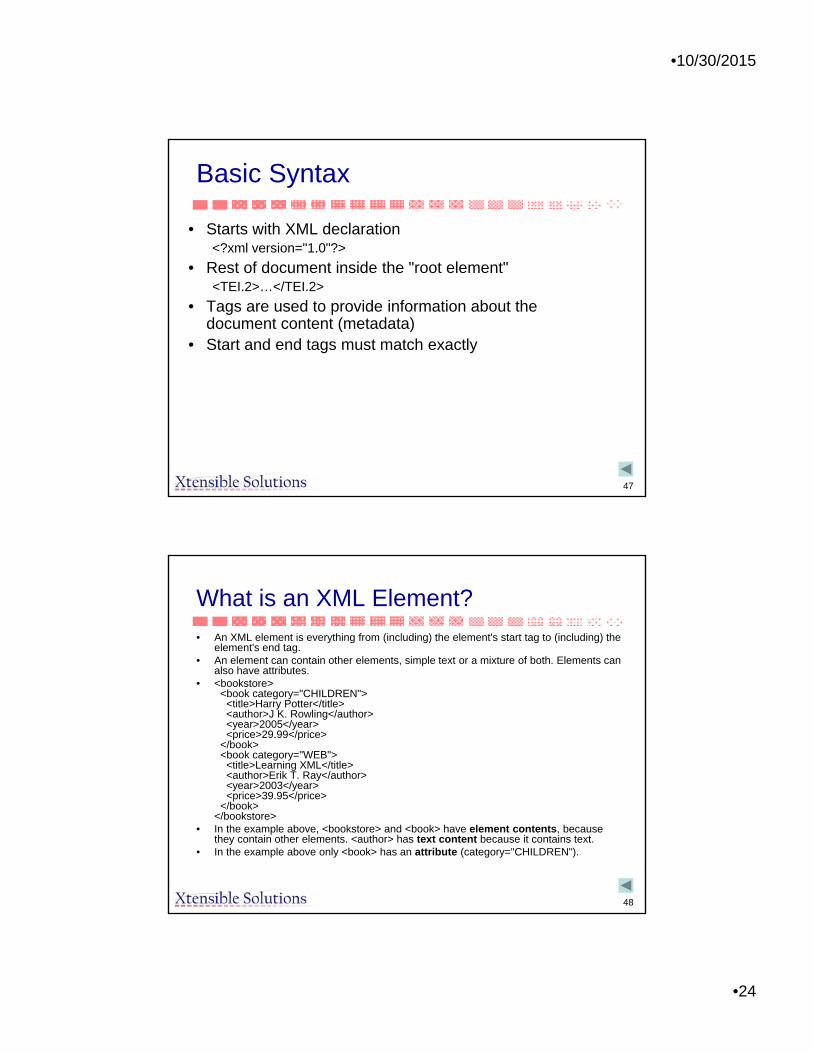
Basic Syntax
• Starts with XML declaration<?xml version="1.0"?>
• Rest of document inside the "root element"<TEI.2>…</TEI.2>
• Tags are used to provide information about the document content (metadata)
• Start and end tags must match exactly
48
What is an XML Element?
• An XML element is everything from (including) the element's start tag to (including) the element's end tag.
• An element can contain other elements, simple text or a mixture of both. Elements can also have attributes.
• <bookstore><book category="CHILDREN">
<title>Harry Potter</title><author>J K. Rowling</author><year>2005</year><price>29.99</price>
</book><book category="WEB">
<title>Learning XML</title><author>Erik T. Ray</author><year>2003</year><price>39.95</price>
</book></bookstore>
• In the example above, <bookstore> and <book> have element contents, because they contain other elements. <author> has text content because it contains text.
• In the example above only <book> has an attribute (category="CHILDREN").

•10/30/2015
•25
49
Implementation Syntax – XML Schema
• Example of use of XML Schema
• Mapping Proprietary EMS Interfaces to the CIM– Provide enterprise system access to transformer data
50
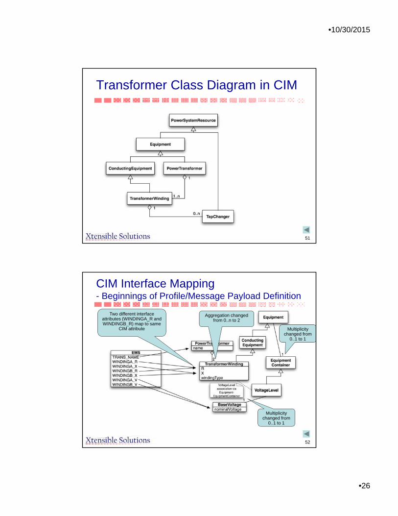
Mapping EMS Interfaces to the CIM –User access to transformer data
• EMS Native Interface attributes:– TRANS_NAME – The Transformer’s name
– WINDINGA_R – The Transformer’s primary winding resistance
– WINDINGA_X – The Transformer’s primary winding reactance
– WINDINGB_R – The Transformer’s secondary winding resistance
– WINDINGB_X – The Transformer’s secondary winding reactance
– WINDINGA_V – The Transformer’s primary winding voltage
– WINDINGB_V – The Transformer’s secondary winding voltage
•10/30/2015
•26
51
Transformer Class Diagram in CIM
52
CIM Interface Mapping- Beginnings of Profile/Message Payload Definition
Two different interface attributes (WINDINGA_R and WINDINGB_R) map to same
CIM attribute
Aggregation changed from 0..n to 2
Multiplicity changed from
0..1 to 1
Multiplicity changed from
0..1 to 1
•10/30/2015
•27
53
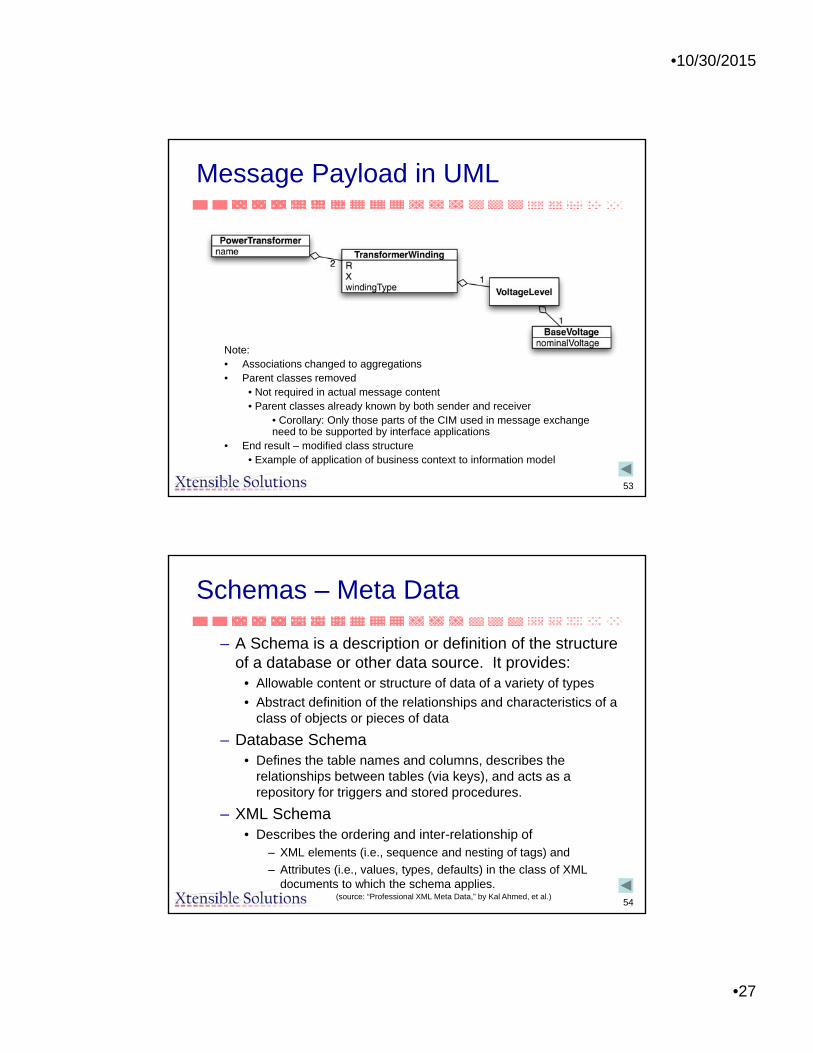
Message Payload in UML
Note:• Associations changed to aggregations• Parent classes removed
• Not required in actual message content• Parent classes already known by both sender and receiver
• Corollary: Only those parts of the CIM used in message exchange need to be supported by interface applications
• End result – modified class structure• Example of application of business context to information model
54
Schemas – Meta Data
– A Schema is a description or definition of the structure of a database or other data source. It provides:
• Allowable content or structure of data of a variety of types
• Abstract definition of the relationships and characteristics of a class of objects or pieces of data
– Database Schema• Defines the table names and columns, describes the
relationships between tables (via keys), and acts as a repository for triggers and stored procedures.
– XML Schema• Describes the ordering and inter-relationship of
– XML elements (i.e., sequence and nesting of tags) and
– Attributes (i.e., values, types, defaults) in the class of XML documents to which the schema applies.
(source: “Professional XML Meta Data,” by Kal Ahmed, et al.)

•10/30/2015
•28
55
XML Schema of CIM
• An XML Schema of the CIM can be generated with XML tools
• The CIM classes and attributes are used to define tags
• Then the CIM can be shown in XML as well as UML
• Example is PowerTransformer
56
Transformer Model Diagram from 61970-301CIM Base
ConductingEquipment(from Core)
Equipment(from Core)
PowerSystemResource(from Core)
RegulationSchedule
TapChanger
0..1
0..n
+RegulationSchedule0..1
+TapChangers
0..n
WindingTest
HeatExchanger
TransformerWinding
0..n+TapChangers
0..n
+TransformerWinding
1
1
0..n
+From_TransformerWinding1
+From_WindingTests1
0..n
+To_WindingTest
+To_TransformeWindings0..n
PowerTransformer
0..1
1
+HeatExchanger0..1
+PowerTransformer 1
1..n
1
+Contains_TransformerWindings
+MemberOf_PowerTransformer
1
•10/30/2015
•29
57
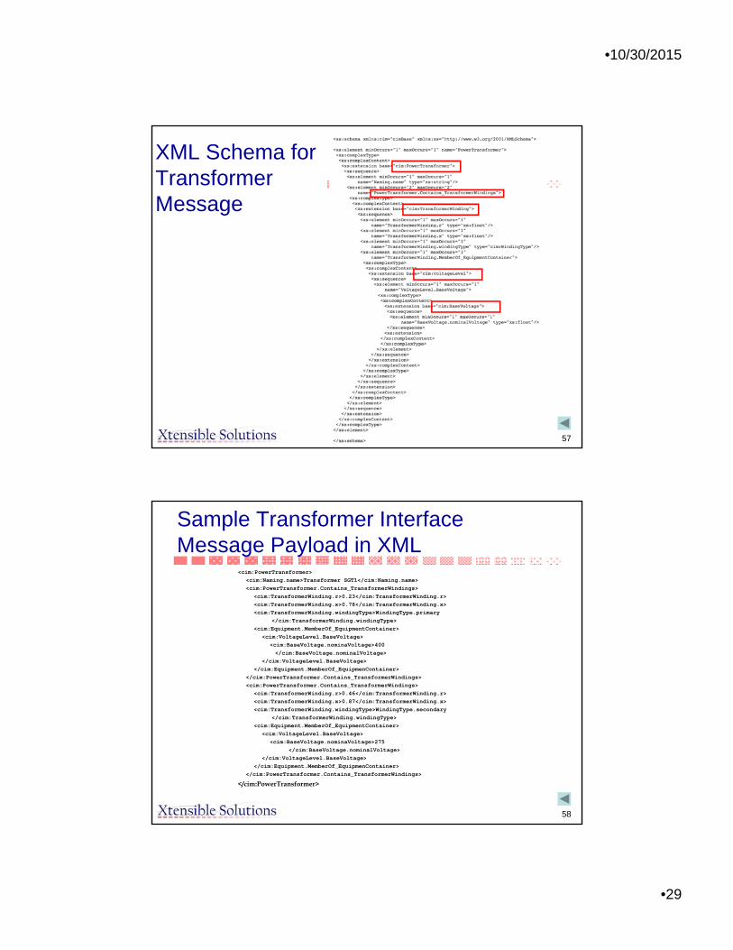
XML Schema for Transformer Message
58
Sample Transformer Interface Message Payload in XML
<cim:PowerTransformer>
<cim:Naming.name>Transformer SGT1</cim:Naming.name>
<cim:PowerTransformer.Contains_TransformerWindings>
<cim:TransformerWinding.r>0.23</cim:TransformerWinding.r>
<cim:TransformerWinding.x>0.78</cim:TransformerWinding.x>
<cim:TransformerWinding.windingType>WindingType.primary
</cim:TransformerWinding.windingType>
<cim:Equipment.MemberOf_EquipmentContainer>
<cim:VoltageLevel.BaseVoltage>
<cim:BaseVoltage.nominaVoltage>400
</cim:BaseVoltage.nominalVoltage>
</cim:VoltageLevel.BaseVoltage>
</cim:Equipment.MemberOf_EquipmenContainer>
</cim:PowerTransformer.Contains_TransformerWindings>
<cim:PowerTransformer.Contains_TransformerWindings>
<cim:TransformerWinding.r>0.46</cim:TransformerWinding.r>
<cim:TransformerWinding.x>0.87</cim:TransformerWinding.x>
<cim:TransformerWinding.windingType>WindingType.secondary
</cim:TransformerWinding.windingType>
<cim:Equipment.MemberOf_EquipmentContainer>
<cim:VoltageLevel.BaseVoltage>
<cim:BaseVoltage.nominaVoltage>275
</cim:BaseVoltage.nominalVoltage>
</cim:VoltageLevel.BaseVoltage>
</cim:Equipment.MemberOf_EquipmenContainer>
</cim:PowerTransformer.Contains_TransformerWindings>
</cim:PowerTransformer>

•10/30/2015
•30
59
XML Implementation Technologies
• XML Schema– Used for generation of message payloads for system
interfaces in system integration use cases
• RDF Schema– Used for exchange of power system models
60
Big Issue
• “Although we can swap our documents with each other through XML, we still haven’t a clue what they mean.”
» (“Professional XML Meta Data,” by Kal Ahmed, et al.)
• Resource Description Framework (RDF) Is W3C’s Means To Resolve This.

•10/30/2015
•31
61
RDF Schema
• RDF Schema mechanism is a set of RDF resources (including properties) and constraints on their relationships
• Defines application-specific RDF vocabularies, for example CIM vocabulary
• RDF Schema URI unambiguously identifies a single version of a schema
[Courtesy Of Leila Schneburger]
62
Technical Approach
• RDF (Resource Description Framework) - Defines mechanism for describing resources that makes no assumptions about a particular application domain, nor defines the semantics of any application domain. The definition of the mechanism is domain neutral, yet the mechanism is suitable for describing information about any domain:– For more information: http://www.w3.org/RDF– Status: W3C Recommendation 22 February 1999
• http://www.w3.org/TR/REC-rdf-syntax/
• RDF Schema - Defines a schema specification language. Provides a basic type system for use in RDF models. It defines resources and properties such as Class and subClassOf that are used in specifying application-specific schemas:– Status: W3C Proposed Recommendation 03 March 1999
• http://www.w3.org/TR/PR-rdf-schema/
•10/30/2015
•32
63
Technical Approach (Cont.)
• Namespaces
- provide a simple method for qualifying element and attribute names used in XML documents by associating them with namespaces identified by URI references:
– Status: WC3 Recommendation 14-January-1999• http://www.w3.org/TR/REC-xml-names/
• URI (Uniform Resource Identifiers)- provide a simple and extensible means for identifying a resource:
– Status: Internet RFC August 1998• ftp://ftp.isi.edu/in-notes/rfc2396.txt
64
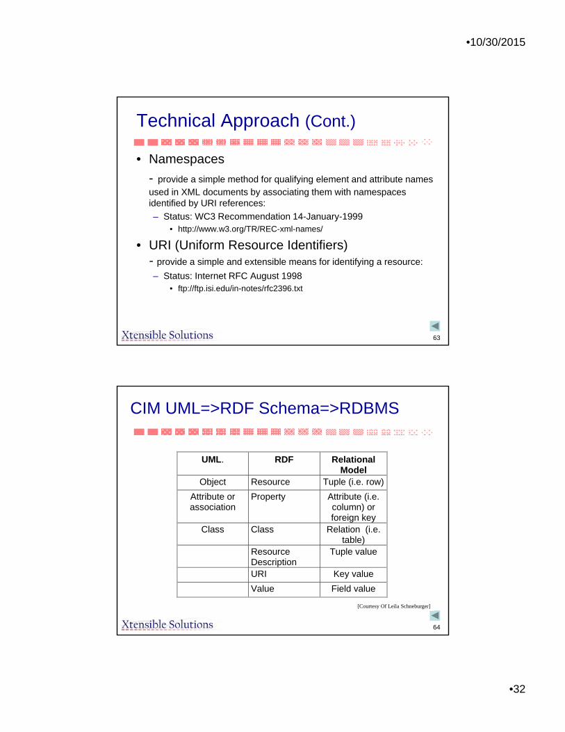
CIM UML=>RDF Schema=>RDBMS
UML. RDF Relational Model
Object Resource Tuple (i.e. row)
Attribute or association
Property Attribute (i.e. column) or foreign key
Class Class Relation (i.e. table)
Resource Description
Tuple value
URI Key value
Value Field value
[Courtesy Of Leila Schneburger]

•10/30/2015
•33
65
Siemens 100 Bus Network Model in RDF
<?xml version="1.0" encoding="UTF-8"?><rdf:RDF xml:base="siemens" xmlns:rdf="http://www.w3.org/1999/02/22-rdf-syntax-ns#" xmlns:cim="http://iec.ch/TC57/2001/CIM-schema-cim10#"><cim:ACLineSegment rdf:ID="_6B1DD5C2CB934E86AC53FFD886E2D1B3"><cim:Naming.name>BBD-RSK2</cim:Naming.name><cim:Conductor.bch>2.79</cim:Conductor.bch><cim:Conductor.x>4.3378</cim:Conductor.x><cim:Conductor.r>0.4761</cim:Conductor.r></cim:ACLineSegment><cim:Terminal rdf:ID="_EB6085D9DF364DA78A884D4D0A571371"><cim:Naming.name>T2</cim:Naming.name><cim:Terminal.ConnectivityNode rdf:resource="#_CC312D30C85C4236948A4129AEE3B5F7"/><cim:Terminal.ConductingEquipment rdf:resource="#_6B1DD5C2CB934E86AC53FFD886E2D1B3"/></cim:Terminal><cim:Terminal rdf:ID="_7C8354E0DA247DBB3611E2E8BF8A86D"><cim:Naming.name>T1</cim:Naming.name><cim:Terminal.ConnectivityNode rdf:resource="#_D16FD63501444AECBF8157D1E4764E38"/><cim:Terminal.ConductingEquipment rdf:resource="#_6B1DD5C2CB934E86AC53FFD886E2D1B3"/></cim:Terminal><cim:ACLineSegment rdf:ID="_E83B07FE54A945539A95FD2DB2CDD4FC"><cim:Naming.name>BKR-TUR</cim:Naming.name><cim:Conductor.bch>0.39</cim:Conductor.bch><cim:Conductor.x>4.1262</cim:Conductor.x><cim:Conductor.r>1.0051</cim:Conductor.r></cim:ACLineSegment><cim:Terminal rdf:ID="_E273D9258F9D42FCA018B274BE6F5FA6"><cim:Naming.name>T2</cim:Naming.name><cim:Terminal.ConnectivityNode rdf:resource="#_576B6D171B174B8BACB7AFF7289D0434"/><cim:Terminal.ConductingEquipment rdf:resource="#_E83B07FE54A945539A95FD2DB2CDD4FC"/></cim:Terminal><cim:Terminal rdf:ID="_B23175B9692441AFBD2C581E86300550"><cim:Naming.name>T1</cim:Naming.name><cim:Terminal.ConnectivityNode rdf:resource="#_A69ED82F4EB4B65A8840CDD1E064887"/><cim:Terminal.ConductingEquipment rdf:resource="#_E83B07FE54A945539A95FD2DB2CDD4FC"/></cim:Terminal><cim:Unit rdf:ID="_5EAAD38A446E429E9905FAC32070D6FC"><cim:Naming.name>Amperes</cim:Naming.name></cim:Unit><cim:ACLineSegment rdf:ID="_329884C01F6B4DC08492F711088538D6"><cim:Naming.name>CRS-ANY1</cim:Naming.name><cim:Conductor.bch>5.03</cim:Conductor.bch><cim:Conductor.x>12.90761</cim:Conductor.x><cim:Conductor.r>1.2696</cim:Conductor.r></
Top of RDF Schema version of Siemens 100 bus model
66
CIM Usage
• Many EMS vendors support power system model exchange using CIM/RDF/XML, some with CIM-based databases behind the scenes
• EPRI has sponsored 12 interoperability tests for transmission model exchange and service validation and more recently for planning and distribution
• Utilities have implemented CIM-based integration using EAI technologies– Utilities have used the CIM as the basis for developing common messages for integration
• Asset and work management vendors as well as GIS application vendors are supporting CIM/XSD standards
• AMI (Smart Meter) projects use IEC 61968 Part 9 for meter related information exchange
• CIM has been extended into the power market, planning, and dynamic model exchange
• CIM provides a foundation for Service-Oriented Architecture (SOA) and Web service implementations
• Vendors have developed tools to build CIM-based information exchange messaging, ESB and OPC interfaces, and repository applications that can process CIM-aware data
• MultiSpeak is converting to CIM-based UML models and XML• ENTSO_E is converting power model exchanges and day-ahead forecasts for
planning/operational applications to CIM based format– Second IOP conducted in July 2010 (first was UCTE IOP in March 2009)
• Many Smart Grid-related activities based on CIM– Separate presentations during week

•10/30/2015
•34
67
Concluding Remarks
• Bottom line: CIM standards are different and much more powerful– Can be applied in many ways
– Support many types of functions/applications through combination of reuse and extension
– Architecture supports future, unknown applications