Embed Size (px)
Citation preview
Introduction to Cased-Hole Data
Acquisition and Interpretation
Permanent Temperature Profiling
Overview
1- Well Integrity
• Cementing: Cementing is a critical part of any well competition and subsequently
well integrity. Poor cementing is responsible for casing outer wall corrosion, leaks
and subsequently casing collapse.
• Corrosion: Corrosion is initiated immediately after placing the casing. The rate of
corrosion depends on many factors such as casing metallurgy, poor cementing and
casing stresses- to quote a few.
• Leaks: Leaks in casings and tubing will materialize in the long run. This again is a
function of the metallurgy, cementing and borehole environment.
2- Production Logging:
• Water, oil and gas production from every zone.
• Productivity index and pressure for each zone
• Detection of leaks behind and inside casings
• Estimation of cross-flow between zones caused by uneven depletion.
• Three phase production in horizontal wells.
3- Reservoir Monitoring:
• Estimating fluid saturations of water, oil and gas behind conductive and non-
conductive casings
• Applications of Pulsed neutron logging: capture mode (Σ) and Carbon/Oxygen
mode.
• Resistivity (Rt) measurements behind conductive and non-conductive casings.
• Evaluating stand-alone PNL logs in old wells.
Annulus bleed-off
Leak response
Pe
rman
en
t Se
nso
rs
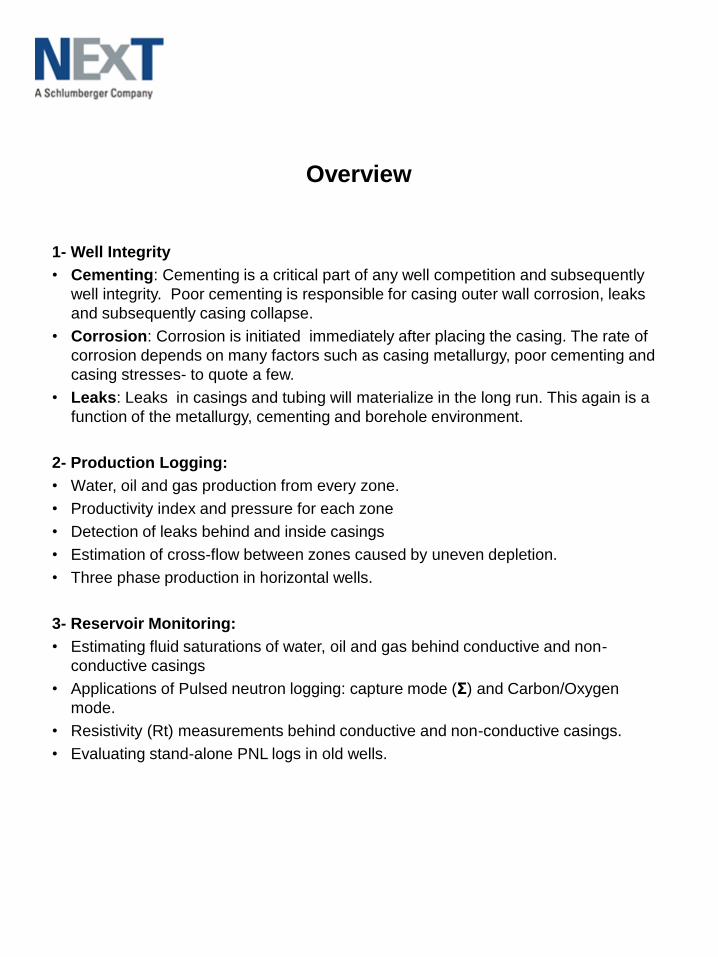
Leak Detections- Temperature profiling:
There are many forms of logging that are used to detect leaks (temperature, noise,
oxygen activation, Injectivity). The most effective form is temperature profiling. The
examples above show:
Permanent Temperature sensors using fibre optics: This will become almost
standard in the future where the temperature profiles continuously monitored.
Standard E-Line temperature logging: The example on the right shows the
geothermal logs for 20 wells. 3 of the wells show a deviation from the geothermal.
An increase above geothermal means leak up behind the casing, and a decrease
below the geothermal mean leak down ward.
Well Integrity: Leak Detection/Temperature Profiling
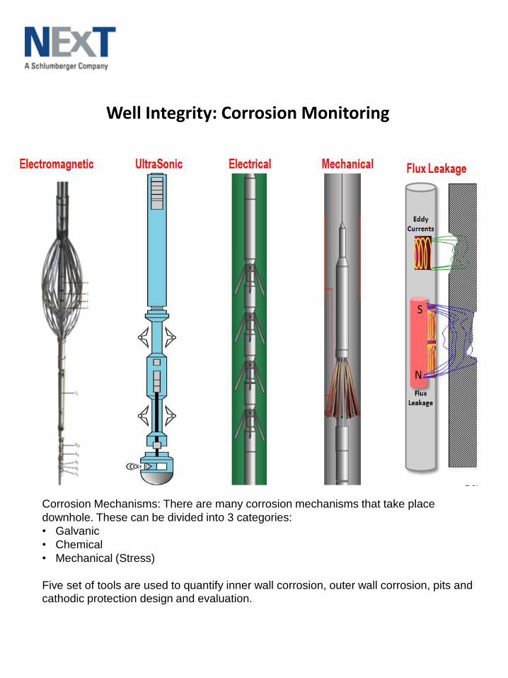
Well Integrity: Corrosion Monitoring
Corrosion Mechanisms: There are many corrosion mechanisms that take place
downhole. These can be divided into 3 categories:
• Galvanic
• Chemical
• Mechanical (Stress)
Five set of tools are used to quantify inner wall corrosion, outer wall corrosion, pits and cathodic protection design and evaluation.
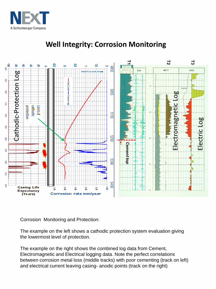
Well Integrity: Corrosion Monitoring
Corrosion Monitoring and Protection:
The example on the left shows a cathodic protection system evaluation giving
the lowermost level of protection.
The example on the right shows the combined log data from Cement,
Electromagnetic and Electrical logging data. Note the perfect correlations
between corrosion metal loss (middle tracks) with poor cementing (track on left)
and electrical current leaving casing- anodic points (track on the right)
Elec
tric
Lo
g
Elec
tro
mag
net
ic L
og
Cat
ho
dic
-Pro
tect
ion
Lo
g
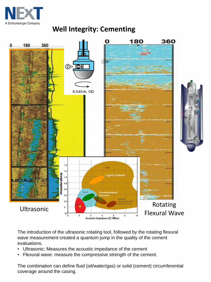
UltrasonicRotating
Flexural Wave
The introduction of the ultrasonic rotating tool, followed by the rotating flexural
wave measurement created a quantum jump in the quality of the cement
evaluations.
• Ultrasonic: Measures the acoustic impedance of the cement
• Flexural wave: measure the compressive strength of the cement.
The combination can define fluid (oil/water/gas) or solid (cement) circumferential coverage around the casing.
Well Integrity: Cementing
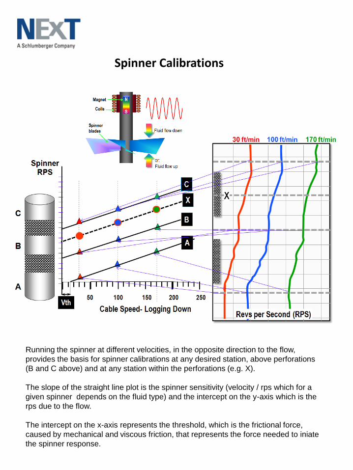
Spinner Calibrations
Running the spinner at different velocities, in the opposite direction to the flow,
provides the basis for spinner calibrations at any desired station, above perforations
(B and C above) and at any station within the perforations (e.g. X).
The slope of the straight line plot is the spinner sensitivity (velocity / rps which for a
given spinner depends on the fluid type) and the intercept on the y-axis which is the
rps due to the flow.
The intercept on the x-axis represents the threshold, which is the frictional force,
caused by mechanical and viscous friction, that represents the force needed to iniate
the spinner response.
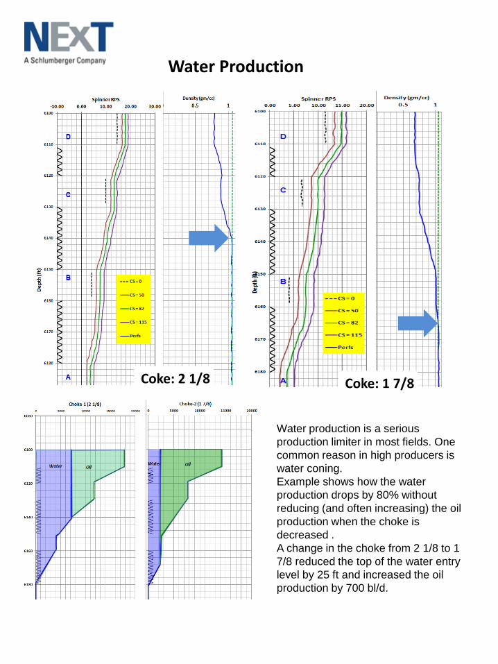
Water Production
Water production is a serious
production limiter in most fields. One
common reason in high producers is
water coning.
Example shows how the water
production drops by 80% without
reducing (and often increasing) the oil
production when the choke is
decreased .
A change in the choke from 2 1/8 to 1
7/8 reduced the top of the water entry
level by 25 ft and increased the oil
production by 700 bl/d.
Coke: 2 1/8 Coke: 1 7/8
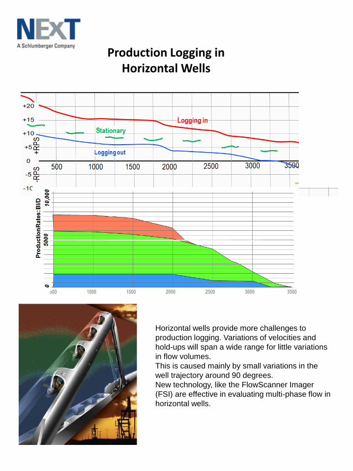
Production Logging in Horizontal Wells
Horizontal wells provide more challenges to
production logging. Variations of velocities and
hold-ups will span a wide range for little variations
in flow volumes.
This is caused mainly by small variations in the
well trajectory around 90 degrees.
New technology, like the FlowScanner Imager
(FSI) are effective in evaluating multi-phase flow in
horizontal wells.
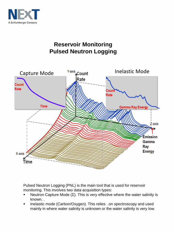
Reservoir Monitoring
Pulsed Neutron Logging
Pulsed Neutron Logging (PNL) is the main tool that is used for reservoir
monitoring. This involves two data acquisition types:
Neutron Capture Mode (Σ). This is very effective where the water salinity is
known. .
Inelastic mode (Carbon/Oxygen). This relies .on spectroscopy and used
mainly in where water salinity is unknown or the water salinity is very low.
Capture Mode Inelastic Mode
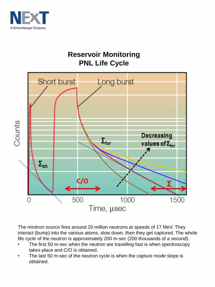
Reservoir Monitoring
PNL Life Cycle
The minitron source fires around 20 million neutrons at speeds of 17 MeV. They
interact (bump) into the various atoms, slow down, then they get captured. The whole
life cycle of the neutron is approximately 200 m-sec (200 thousands of a second).
• The first 50 m-sec when the neutron are travelling fast is when spectroscopy
takes place and C/O is obtained.
• The last 50 m-sec of the neutron cycle is when the capture mode slope is
obtained.
C/O Σ
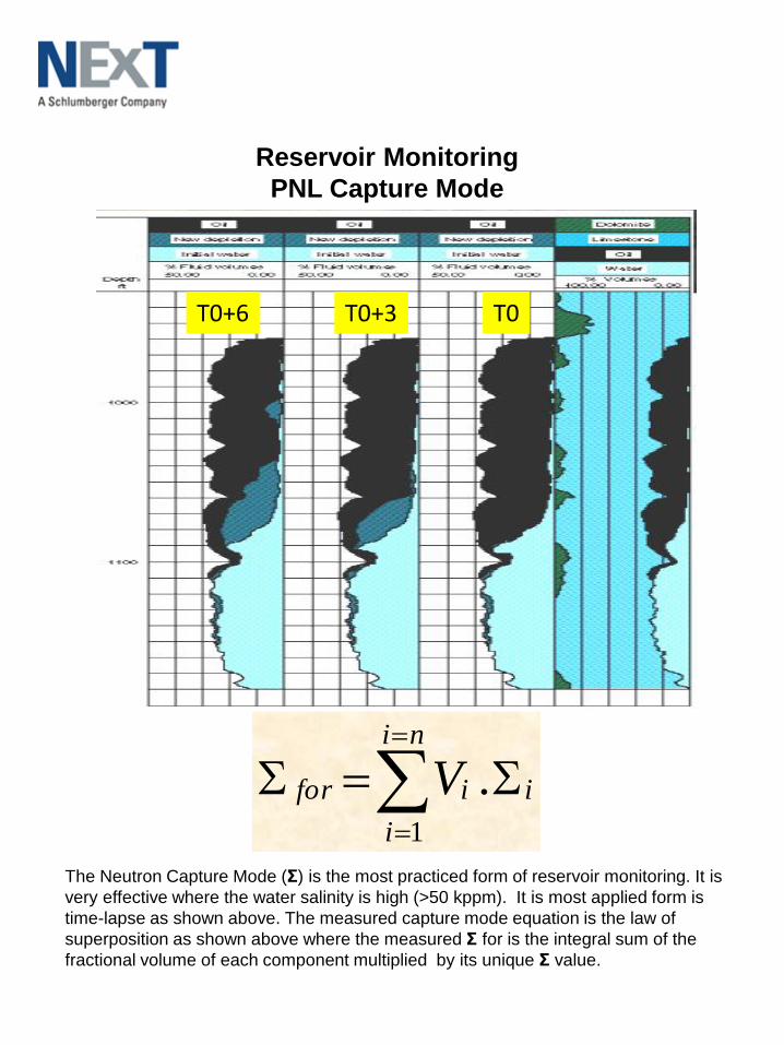
Reservoir Monitoring
PNL Capture Mode
i
ni
i
ifor V
1
.
T0T0+3T0+6
The Neutron Capture Mode (Σ) is the most practiced form of reservoir monitoring. It is
very effective where the water salinity is high (>50 kppm). It is most applied form is
time-lapse as shown above. The measured capture mode equation is the law of
superposition as shown above where the measured Σ for is the integral sum of the
fractional volume of each component multiplied by its unique Σ value.
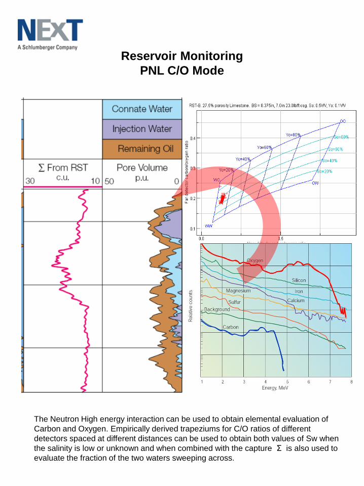
Reservoir Monitoring
PNL C/O Mode
The Neutron High energy interaction can be used to obtain elemental evaluation of
Carbon and Oxygen. Empirically derived trapeziums for C/O ratios of different
detectors spaced at different distances can be used to obtain both values of Sw when
the salinity is low or unknown and when combined with the capture Σ is also used to
evaluate the fraction of the two waters sweeping across.
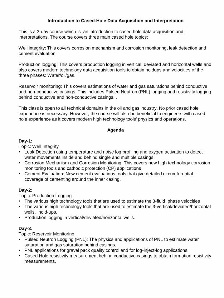
Introduction to Cased-Hole Data Acquisition and Interpretation
This is a 3-day course which is an introduction to cased hole data acquisition and
interpretations. The course covers three main cased hole topics:
Well integrity: This covers corrosion mechanism and corrosion monitoring, leak detection and
cement evaluation
Production logging: This covers production logging in vertical, deviated and horizontal wells and
also covers modern technology data acquisition tools to obtain holdups and velocities of the
three phases: Water/oil/gas.
Reservoir monitoring: This covers estimations of water and gas saturations behind conductive
and non-conductive casings. This includes Pulsed Neutron (PNL) logging and resistivity logging
behind conductive and non-conductive casings. .
This class is open to all technical domains in the oil and gas industry. No prior cased hole
experience is necessary. However, the course will also be beneficial to engineers with cased
hole experience as it covers modern high technology tools' physics and operations.
Agenda
Day-1:
Topic: Well Integrity
• Leak Detection using temperature and noise log profiling and oxygen activation to detect
water movements inside and behind single and multiple casings.
• Corrosion Mechanism and Corrosion Monitoring. This covers new high technology corrosion
monitoring tools and cathodic protection (CP) applications
• Cement Evaluation: New cement evaluations tools that give detailed circumferential
coverage of cementing around the inner casing.
Day-2:
Topic: Production Logging
• The various high technology tools that are used to estimate the 3-fluid phase velocities
• The various high technology tools that are used to estimate the 3-vertical/deviated/horizontal
wells. hold-ups.
• Production logging in vertical/deviated/horizontal wells.
Day-3:
Topic: Reservoir Monitoring
• Pulsed Neutron Logging (PNL): The physics and applications of PNL to estimate water
saturation and gas saturation behind casings.
• PNL applications for gravel pack quality control and for log-inject-log applications.
• Cased Hole resistivity measurement behind conductive casings to obtain formation resistivity
measurements.