Embed Size (px)
Citation preview

© 2008 Cisco Systems, Inc. All rights reserved. Cisco Public 1
Introduction to 802.11 Technology
Suebpong NitichaiEmail: [email protected]

2© 2008 Cisco Systems, Inc. All rights reserved. Cisco Public
IEEE 802.11 Standard define :
A Physical layerRadio Frequencies, Data Modulation, …(802.11, 802.11b, 802.11g, 802.11a, 802.11n, …)
A MAC layerHow to access the medium, how to manage the collisions, …
IEEE 802.11 FamilyTechnology Overview

3© 2008 Cisco Systems, Inc. All rights reserved. Cisco Public
IEEE 802.11b
Ratified as standard in Sept, 1999
Uses 2.4 GHz unlicensed spectrum
Different physical access defined (PHY)
Direct sequence at 1, 2, 5.5, and 11 Mbps, Can ―downshift‖ to lower data rates for longer range
Frequency hopping at 1 and 2 Mbps for 2.4 Ghz (legacy)
Infrared (obsolete)
11 US channels, 13 ETSI channels, 14 Japan channels
Generally approved for worldwide use in many countries

4© 2008 Cisco Systems, Inc. All rights reserved. Cisco Public
IEEE 802.11bDirect Sequence @ 2.4 GHz
Up to (14) 22 MHz wide channels
3 non-overlapping channels (1, 6, 11)
Up to 11 Mbps data rate
3 access points can occupy the same space for a total of 33 Mbps aggregate throughput, but not on same radio card
1 2 6 113 4 5 7 8 9 12 13 1410
2.402 GHz 2.483 GHz
Channels

5© 2008 Cisco Systems, Inc. All rights reserved. Cisco Public
IEEE 802.11g
Ratified as standard in June, 2003
Same frequencies as IEEE 802.11b (2.4 GHz)
Backward compatible with 802.11b
Orthogonal Frequency Division Multiplexing (OFDM)
Data rates supported: 54, 48, 36, 24, 12, and 6 Mbps
Direct sequence(802.11b backwards compatible)
Data rates: 1, 2, 5.5, and 11 Mbps
11 Mbps
802.11b 802.11g
802.11b
11 Mbps
802.11b
802.11g
54 Mbps
802.11g

6© 2008 Cisco Systems, Inc. All rights reserved. Cisco Public
IEEE 802.11a
Ratified as standard in Sept, 1999
Orthogonal Frequency Division Multiplexing (OFDM)
Data rates supported: 54, 48, 36, 24, 12, and 6 Mbps
Can ―downshift‖ to lower data rates for longer range
Compliant in some countries
5 GHz band has more channels than 2.4 GHz band
19 non-overlapping channels in ETSI Regulation Area
(vs. 3 channels for 2.4 GHz) for greater scalability
7© 2008 Cisco Systems, Inc. All rights reserved. Cisco Public
Current State of 5 GHz Bridging Spectrum
23 dBm
200mW
Hub Radios
Licensed
UNII-3, 30 dBm
Europe*
5.15 5.35 5.470 5.7255.825
5.25
UNII-117 dBm
UNII-224 dBm
US
(FCC)
4 Channels 4 Channels
5 Channels
11 Channels
30 dBm
1W
23 dBm
200mW
4.94 4.99
20 dBm
Japan DFS + TPC
Spectral Mask
Designators (20 MHz)
Dynamic Frequency Selection (DFS)Target Power Control (TPC)
5.8502 Channels
1500 AP
4 ChannelsConducted Power
Tx Output Power
Radiated Power
EIRP (with Antenna)
TBD
ISM 30 dBm
*Check regulation for your own country

8© 2008 Cisco Systems, Inc. All rights reserved. Cisco Public
IEEE 802.11 Radio SummaryProperties
802.11 802.11b 802.11g 802.11a
Ratified 1999 1999 2003 1999
Data Rates (Mbps)
1,2 1,2,5.5,111,2,5.5,11 and 6,9,12,18,24,
36,48,54
6,9,12,18,24,36,48,54
Number of Non-Overlapping Channels
Frequency Hopping
3 38 Indoors/
11 Outdoors
Frequency Range (GHz)
2.402–2.4835.15–5.35,
5.47–5.725*
Status Obsolete Worldwide AvailableLimited
Worldwide Availability

9© 2008 Cisco Systems, Inc. All rights reserved. Cisco Public
Introduction to the Cisco Unified Wireless Network
10© 2008 Cisco Systems, Inc. All rights reserved. Cisco Public
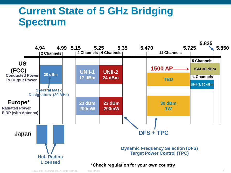
Understanding WLAN Controllers—1st/2nd
Generation vs. 3rd Generation Approach
1st/2nd generation—APs act as 802.1Q translational bridge, putting client traffic on local VLANs
3rd generation—Controller bridges client traffic centrally
1st/2nd Generation
3rd Generation

11© 2008 Cisco Systems, Inc. All rights reserved. Cisco Public
Centralized Wireless LAN ArchitectureOverview
Processing split between APs and controllers
802.11 functionality shared
Central management—AP is essentially a remote RF interface
Based on LWAPP protocol
APs hold no security credentials
APs unusable without a controller—Just expensive paperweights!
Data traffic can be bridged locally or at controller
Cisco WLAN Controller
LWAPP

12© 2008 Cisco Systems, Inc. All rights reserved. Cisco Public
Centralized Wireless LAN ArchitectureAP/Controller: Division of Labor
Controller
802.11 MAC Mgmt – (re)association requests & action frames
802.11 data – encapsulate and sent to AP
802.11e resource reservation – control protocol carried to AP in 802.11 mgmt frames – signaling done in the controller.
802.11i authentication & key exchange
AP
802.11 – beacons, probe response, auth (if open)
802.11 control – packet ack & retransmission (latency)
802.11e – frame queuing & packet prioritization (real-time access)
802.11i – Layer 2 encryptionLightweight
Access Points
Cisco WLAN Controller
LWAPP

13© 2008 Cisco Systems, Inc. All rights reserved. Cisco Public
LWAPP
Centralized Wireless LAN ArchitectureWhat Is LWAPP?
LWAPP—Light weight access point protocol is used between APs and WLAN controller
LWAPP carries control and data traffic between the two
Control plane is AES-CCM encrypted
Data plane is not encrypted
It facilitates centralized management and automated configuration
Open, standards-based protocol (submitted to IETF CAPWAP WG)
Access Point Controller
WiFi Client
Business Application
Control Plane
Data Plane

14© 2008 Cisco Systems, Inc. All rights reserved. Cisco Public
Difference between LWAPP and CAPWAP
Description LWAPP CAPWAP
Fragmentation/Re-assembly Relies on IpV4 CAPWAP itself does both
Path-MTU Discovery Not supported Has a robust P-MTU discovery mechanism, can also detect dynamic MTU
changes
Control Channel Encryption between AP and WLC
Yes (using AES) Yes (Using DTLS)
Data Channel Encryption between AP and WLC
No Yes (using DTLS)
UDP Ports 12222, 12223 5246 (ctrl) 5247 (data)

15© 2008 Cisco Systems, Inc. All rights reserved. Cisco Public
LWAPP-L2
LWAPP ModesLayer 2 and Layer 3 LWAPP
Layer 2 LWAPP is in an Ethernet frame
AP and WLC in same L2 domain
Layer 3 LWAPP is in a UDP/IP frame
AP need IP address
Support routing between AP and WLC
Lightweight
Access Points
Cisco WLAN Controller
LWAPP-L3
Lightweight
Access Points
Cisco WLAN Controller
LWAPP-L3
LWAPP-L3 Is Now the Preferred Solution
16© 2008 Cisco Systems, Inc. All rights reserved. Cisco Public
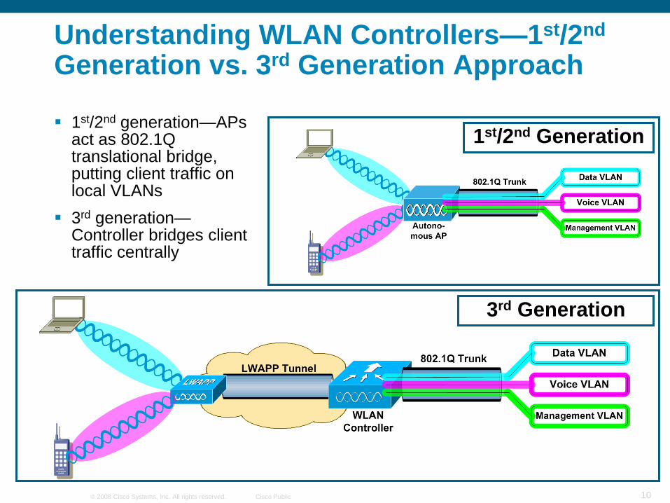
Architecture Deployment
Hunting phase: AP needs to find WLC
Join phase: AP associates securely with WLC
Authorization phase: WLC accept or not AP
Configuration phase: WLC upload firmware (if needed), WLC upload AP configuration
Where IsMy WLC?
Lightweight
Access Points Cisco WLAN Controller
Access Points Need to Be Associated with WLAN Controller

17© 2008 Cisco Systems, Inc. All rights reserved. Cisco Public
LWAPP State Machine (Simplified)
LWAPP defines a state
machine that governs the AP
and controller behavior
Major states:
Discovery—AP looks for a controller
Join—AP attempts to establish a
secured relationship with a controller
Image Data—AP downloads code
from controller
Config—AP receives configuration
from controller
Run—AP and controller operate
normally and service data
Reset—AP clears state and starts
over
Note: LWAPP/CAPWAP RFC
defines other states

18© 2008 Cisco Systems, Inc. All rights reserved. Cisco Public
Components of Centralized Architecture
WLC
Cisco Unified Wireless LAN controllers aggregrate WLAN client traffic and
control the Wireless network
APs
Lightweight access points are used in all unified wireless architectures and
provides client wireless access, and tunneling to the WLC.
WCS
Cisco Wireless Control System provides centralized management, RF planning
and visualization tools, and location services

19© 2008 Cisco Systems, Inc. All rights reserved. Cisco Public
Deploying with RRM in Mind

20© 2008 Cisco Systems, Inc. All rights reserved. Cisco Public
RRM—Radio Resource Management
What are RRM’s objectives?
–To dynamically balance the infrastructure and mitigate changes
–Monitor and maintain coverage for all clients
–Manage Spectrum Efficiency so as to provide the optimal throughput under changing conditions
What RRM does not do
–Substitute for a site survey
–Correct an incorrectly architected network
–Manufacture spectrum

21© 2008 Cisco Systems, Inc. All rights reserved. Cisco Public
How Does RRM Do This?
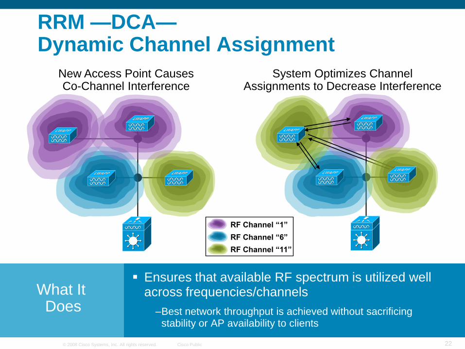
DCA—Dynamic Channel Assignment
–Each AP radio gets a transmit channel assigned to it
–Changes in ―air quality‖ are monitored, AP channel assignment changed when deemed appropriate (based on DCA cost function)
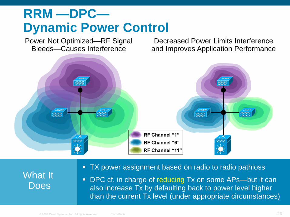
DPC—Dynamic Power Control
–Tx Power assignment based on radio to radio pathloss
–DPC is in charge of reducing Tx on some APs—but may also increase Tx by defaulting back to power level higher than the current Tx level
CHDM—Coverage Hole Detection and Mitigation
–Detecting clients in coverage holes
–Deciding on Tx adjustment (typically Tx increase) on certain APs based on (in)adequacy of estimated downlink client coverage
22© 2008 Cisco Systems, Inc. All rights reserved. Cisco Public
RF Channel ―6‖
RF Channel ―1‖
RF Channel ―11‖
New Access Point Causes Co-Channel Interference
System Optimizes Channel Assignments to Decrease Interference
What ItDoes
RRM —DCA—Dynamic Channel Assignment
Ensures that available RF spectrum is utilized well across frequencies/channels
–Best network throughput is achieved without sacrificing stability or AP availability to clients
23© 2008 Cisco Systems, Inc. All rights reserved. Cisco Public
Power Not Optimized—RF Signal Bleeds—Causes Interference
Decreased Power Limits Interference and Improves Application Performance
What ItDoes
RRM —DPC—Dynamic Power Control
TX power assignment based on radio to radio pathloss
DPC cf. in charge of reducing Tx on some APs—but it can also increase Tx by defaulting back to power level higher than the current Tx level (under appropriate circumstances)
RF Channel ―6‖
RF Channel ―1‖
RF Channel ―11‖

24© 2008 Cisco Systems, Inc. All rights reserved. Cisco Public
Radio Resource ManagementCoverage Hole Detection and Mitigation
Access Point FailureCoverage Hole Detected and Filled
What ItDoes
No single point of failure
Automated network failover decreases support and downtime costs
Wireless network reliability approaches wired
Normal Operation

25© 2008 Cisco Systems, Inc. All rights reserved. Cisco Public
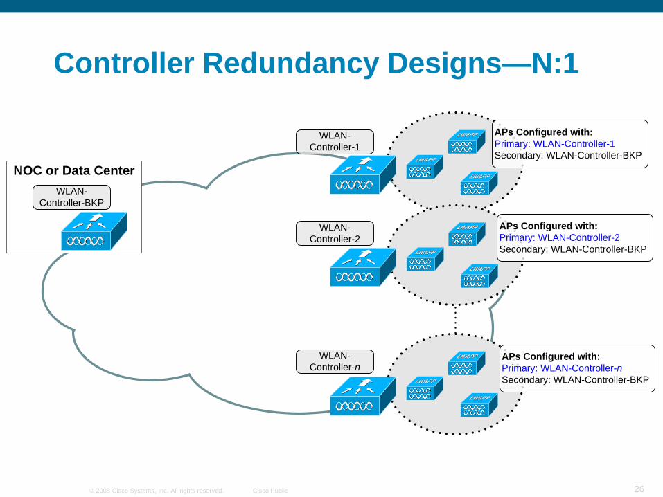
Deterministic Redundancy
Administrator statically assigns APs a primary, secondary, and/or tertiary controller
Assigned from controller interface (per AP) or WCS (template-based)
ProPredictability—Easier operational management
More network stability
More flexible and powerful redundancy design options
Faster failover times
―Fallback‖ option in the case of failover
ConMore upfront planning and configuration
This is Cisco’s recommended best practice!
26© 2008 Cisco Systems, Inc. All rights reserved. Cisco Public
Controller Redundancy Designs—N:1
WLAN-
Controller-BKP
NOC or Data Center
APs Configured with:
Primary: WLAN-Controller-1
Secondary: WLAN-Controller-BKP
WLAN-
Controller-1
WLAN-
Controller-2
WLAN-
Controller-n
APs Configured with:
Primary: WLAN-Controller-2
Secondary: WLAN-Controller-BKP
APs Configured with:
Primary: WLAN-Controller-n
Secondary: WLAN-Controller-BKP

27© 2008 Cisco Systems, Inc. All rights reserved. Cisco Public
Campus WLAN Controller Options
Standalone appliance
controller
Routed network exists on another
platform
Dot1Q trunk to switched/routed
network
Integrated controller
Routed network can exist on the
same platform
Layer 2 connection is internal
Layer 2 or 3 connection to network
routed network
440x
Cisco 3750G Integrated WLAN Controller
WiSM
Integrated
Appliance

28© 2008 Cisco Systems, Inc. All rights reserved. Cisco Public
Where to Place a WLAN Controller?Distributed Designs
WiSM(s) or 440x WLAN
controller(s) connected at
distribution layer
Controller redundancy
Key design considerations:
Spanning tree
HSRP/GLBP
Traffic flow
Load balancing
Resiliency
Access layer ―collapsed‖ into distribution
layer
Access layer IP addressing
Access layer features need to be
implemented in the distribution layer
Mobility!
Layer 2
VoiceDataVoiceAccess
Subnets
Clients
Data
AP AP
WLAN Client Subnets

29© 2008 Cisco Systems, Inc. All rights reserved. Cisco Public
DataDataVoiceAccess
Subnets
Clients
Core
Backbone
AP
Voice
AP
Where to Place a WLAN Controller?Centralized Design—WiSM
Economy of scale
Vertical/Horizontal scalability
―Big Box‖ with 5 WiSMs
Easy to add more capacity
Incremental improvement in cost-per-AP
(CAPEX)
Lower OPEX
Simplified management
Fewer end-points
Aggregation of traffic
HA routing/switching/power
Skilled operational staff
Efficient mobility
Simplified services integration
Key campus design concepts
< 10 msecs latency recommended
Stub network connection
Assumes plenty-of-bandwidth
Could be done with stacks of 440x
Less economy of scale
Not as integrated
Routing/switching design challenges
Service BlockWLAN Client
Subnets

30© 2008 Cisco Systems, Inc. All rights reserved. Cisco Public
Branch Office Deployment—Hybrid REAP
Supported on 1130 and 1240 AP platforms
Allows bridging/tagging of traffic locally (local switching) by WLAN
Allows simultaneous tunneling of traffic to WLC (central switching)
by WLAN
―Connected Mode‖—LWAPP control centralized
―Standalone Mode‖ (WAN outage)
Locally switched WLANs stay up
Some lost functionality
100 msecs latency between APs and WLC
H-REAP APs should be connected to trunk ports—allow only the relevant, locally
switched VLANs
No optimization for:
Fast, secure roaming (CCKM, PKC)
Voice (no CAC or TSPEC support in standalone mode)
Design Considerations:

31© 2008 Cisco Systems, Inc. All rights reserved. Cisco Public
Cisco Secure Services Client
Single Client for Uniform Security and Services
Features
Unified wired and wireless client
Support for industry standards
Endpoint integrity
Single sign-on capable
Enabling of group policies
Administrative control
Benefits
Reduces client software
Simple, secure device connectivity
Minimizes chances of network compromise from infected devices
Reduces complexity
Restricts unauthorized network access
Centralized provisioningSSC
Key Features:
802.1X authentication for wired and wireless devices
Windows XP/2000 support
EAP:
EAP-FAST, EAP-MD5, PEAP-MSCHAP, PEAP-GTC, EAP-TLS, EAP-TTLS, Cisco LEAP
Encryption:
WEP, Dynamic WEP, TKIP, AES
Standards:
WPA and WPA2

32© 2008 Cisco Systems, Inc. All rights reserved. Cisco Public
Wireless Integrated Services Module (WiSM)
Network Core
Delivering Network Unification
Wireless LAN Controller for
ISR Series Routers
2106 Wireless LAN Controller
Branch Office
Hybrid Remote Edge Access Points (H-REAP)
Remote Office
Catalyst 3750GIntegrated WLAN Controller
Intelligent Access
4400 Wireless LAN Controller
Distribution
Lower TCO
ScalabilityHigh
Availability
Ease of Deployment
Investment Protection
Cisco Unified
Wireless
Network
Flexibility

33© 2008 Cisco Systems, Inc. All rights reserved. Cisco Public
Cisco Wireless Control System (WCS)
World-Class Network Management
Features
Client troubleshooting (via CCX)
Planning, configuration, monitoring, location, IDS/IPS, and troubleshooting
Hierarchical maps
Intuitive GUI and templates
Policy based networking (QoS, security, RRM, etc.)
Benefits
Lower OPEX and CAPEX
Better visibility and control of the air
space
Consolidate functionality into a single
management system
Determines location and voice
readiness

34© 2008 Cisco Systems, Inc. All rights reserved. Cisco Public
Guest Access

35© 2008 Cisco Systems, Inc. All rights reserved. Cisco Public
Definition : Guest Access
A solution to offer Internet access to visitors/partners without putting at risk the enterprise Information System.
It’s characteristics are generally :
– It’s Free
– It uses existing enterprise network infrastructure
– Guest traffic must be isolated from intranet traffic
– It does not guaranty radio communication security to guest (no encryption)
– It does it best to protect against impersonation
– It must follow local legal rules (tracking, …)

36© 2008 Cisco Systems, Inc. All rights reserved. Cisco Public
Guest Access Overview
Wireless LAN ControllerGuest Portal
Authentication Gateway
AccessNetworkVisitor
@ Internet
Guest DMZRouting/NAT/FW
Intranet
ManagementLink
WCSLobby AmbassadorVisitor account creation
AP LWAPP
VLANL2 Adjacency
ACS/SyslogRADIUS Accounting
AP LWAPP
AccessNetwork

37© 2008 Cisco Systems, Inc. All rights reserved. Cisco Public
IT Admin Function
Guest User Function
Employee Function
IT Admin Functions
Components of a Guest Access Solution
NetworkSegmentation
GuestProvisioning
GuestLogin Portal
Reporting,Tracking
Guest PolicyManagement
Tunnels or VLANs
Differentiated access by guest
Guest
Guest provisioning web portal
Guest user intercept web auth portal
Audit trails
Legal tracking

38© 2008 Cisco Systems, Inc. All rights reserved. Cisco Public
Guest isolation with Guest DMZOverview
Guest service can use a Wireless Controller inside a Guest DMZ.
Guest traffic will always be encapsulated on the corporate network.
Guest Wireless traffic is transformed in ethernet traffic in Guest DMZ
Guest Traffic can be controled and policed by Cisco ASA Firewall
Wireless LAN
Controller
DMZ
Wireless LAN
Controller
Cisco ASA
Firewall
GuestGuest
LWAPP/CAPWAP
EoIP Tunnel
Internet
Corporate
Intranet

39© 2008 Cisco Systems, Inc. All rights reserved. Cisco Public
Wireless Mesh
40© 2008 Cisco Systems, Inc. All rights reserved. Cisco Public
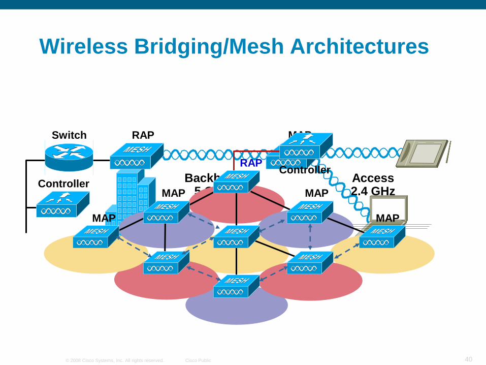
Controller
MAPRAPSwitch
Backhaul5 GHz
Access2.4 GHz
RAPController
MAP
MAP MAP
MAP
Wireless Bridging/Mesh Architectures

41© 2008 Cisco Systems, Inc. All rights reserved. Cisco Public
Installation—RAP Is All About Location
Mount Your Root AP on a Roof Top or Tower That Has a Good View of the Coverage Area
Ideally, You Should See Your RAP Site from the Streetlight or Coverage Area Looking Up

42© 2008 Cisco Systems, Inc. All rights reserved. Cisco Public
Mesh Roles—Root Access Point ―RAP‖

43© 2008 Cisco Systems, Inc. All rights reserved. Cisco Public
Mesh Roles—Mesh Access Point ―MAP‖

44© 2008 Cisco Systems, Inc. All rights reserved. Cisco Public
EquipmentInside
Antennas Installed on the Top of Pole

45© 2008 Cisco Systems, Inc. All rights reserved. Cisco Public
Indoor and Outdoor Deploymentwith Single Controller
Controllers:
WiSM, 44xx and 2106
Mesh Release 2 and later
MAP1
MAP3
MAP2
RAP1
RAP/MAP:
1505, 1510 or 1522
Single Controller Cisco WCS
Managing Indoor and Outdoor
Mesh Wireless Network
Outdoor Wireless Mesh NetworkIndoor Wireless Network
Network Connectivity
Indoor AP:
Mesh & Non Mesh AP’s
iMesh – AP1131 AG & AP1242
RAP
MAP

46© 2008 Cisco Systems, Inc. All rights reserved. Cisco Public
VoIP over WiFiCell Design

47© 2008 Cisco Systems, Inc. All rights reserved. Cisco Public
802.11
a/n
802.11
b/g/n
VoWLAN cell edge designs for 2.4GHz and 5GHz
Channel 1
Channel 11
Channel 6Channel 6
The separation of same channel cells should be: 19 dBm
-67 dBm -86 dBm
The RADIUS of the cell should be:–67 dBm
Channel 1
Channel 11
Channel 6Channel 6
The separation of same channel cells should be: 19 dBm
-67 dBm -86 dBm
The RADIUS of the cell should be:–67 dBm
Channel 36
Channel 40
Channel 44Channel 44
The separation of same channel cells should be: 19 dBm
-72dBm -91dBm
The RADIUS of the cell should be:–72 dBm
Channel 36
Channel 40
Channel 44Channel 44
The separation of same channel cells should be: 19 dBm
-72dBm -91dBm
The RADIUS of the cell should be:–72 dBm
Ideal cell size and channel separation

48© 2008 Cisco Systems, Inc. All rights reserved. Cisco Public
Q and A

49© 2008 Cisco Systems, Inc. All rights reserved. Cisco Public