Embed Size (px)
Citation preview
AUTOCAD 3D (REALEASE 2009)
1.0 Introduction to 3D
1.1 3D Coordinate
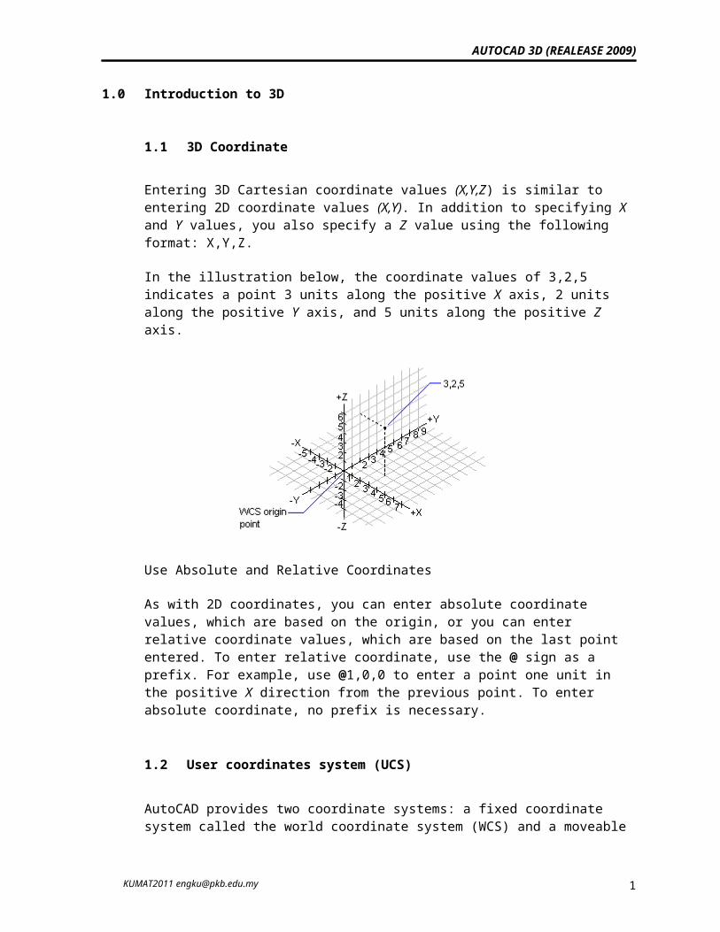
Entering 3D Cartesian coordinate values (X,Y,Z) is similar to entering 2D coordinate values (X,Y). In addition to specifying X and Y values, you also specify a Z value using the following format: X,Y,Z.
In the illustration below, the coordinate values of 3,2,5 indicates a point 3 units along the positive X axis, 2 units along the positive Y axis, and 5 units along the positive Z axis.
Use Absolute and Relative Coordinates
As with 2D coordinates, you can enter absolute coordinate values, which are based on the origin, or you can enter relative coordinate values, which are based on the last point entered. To enter relative coordinate, use the @ sign as a prefix. For example, use @1,0,0 to enter a point one unit in the positive X direction from the previous point. To enter absolute coordinate, no prefix is necessary.
1.2 User coordinates system (UCS)
AutoCAD provides two coordinate systems: a fixed coordinate system called the world coordinate system (WCS) and a moveable coordinate system called the user coordinate system (UCS). The UCS is useful for entering coordinates, defining drawing planes, and setting views. Changing the UCS does not change your viewpoint. It changes only the orientation and tilt of the coordinate system.
If you are creating 3D objects, you can relocate the UCS to simplify your work. For example, if you have created a 3D box, you can edit each of its six sides easily by aligning the UCS with each side as you edit it.
KUMAT2011 [email protected] 1
AUTOCAD 3D (REALEASE 2009)
You relocate a UCS by choosing the location of the origin point and the orientation of the XY plane and the Z axis. You can locate and orient a UCS anywhere in 3D space. Only one UCS is current at any given time, and all coordinate input and display is relative to it. If multiple viewports are displayed, they share the current UCS. With the UCSVP system variable turned on, you can lock a UCS to a viewport, automatically restoring the UCS each time that viewport is made current.
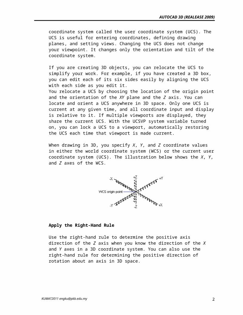
When drawing in 3D, you specify X, Y, and Z coordinate values in either the world coordinate system (WCS) or the current user coordinate system (UCS). The illustration below shows the X, Y, and Z axes of the WCS.
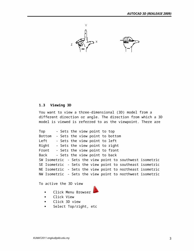
Apply the Right-Hand Rule
Use the right-hand rule to determine the positive axis direction of the Z axis when you know the direction of the X and Y axes in a 3D coordinate system. You can also use the right-hand rule for determining the positive direction of rotation about an axis in 3D space.
1.3 Viewing 3DYou want to view a three-dimensional (3D) model from a different direction or angle. The direction from which a 3D model is viewed is referred to as the viewpoint. There are
KUMAT2011 [email protected] 2
AUTOCAD 3D (REALEASE 2009)
Top - Sets the view point to top Bottom - Sets the view point to bottom Left - Sets the view point to left Right - Sets the view point to rightFront - Sets the view point to front Back - Sets the view point to back SW Isometric - Sets the view point to southwest isometric SE Isometric - Sets the view point to southeast isometric NE Isometric - Sets the view point to northeast isometric NW Isometric - Sets the view point to northwest isometric
To active the 3D view
Click Menu Browser Click View Click 3D view Select Top/right, etc
or
1.4 Visual Style
A visual style is a collection of settings that control the display of edges and shading in the viewport. Instead of using commands and setting system variables, you change the properties of the visual style. As soon as
KUMAT2011 [email protected] 3

AUTOCAD 3D (REALEASE 2009)
you apply a visual style or change its settings, you can see the effect in the viewport.
Five default visual styles are supplied with the product:
2D Wireframe - Displays the objects using lines and curves to represent the boundaries. Raster and OLE objects, linetypes, and lineweights are visible.
3D Wireframe - Displays the objects using lines and curves to represent the boundaries.
3D Hidden - Displays the objects using 3D wireframe representation and hides lines representing back faces.
Realistic - Shades the objects and smooths the edges between polygon faces. Materials that you have attached to the objects are displayed.
Conceptual - Shades the objects and smooths the edges between polygon faces. Shading uses the Gooch face style, a transition between cool and warm colors rather than dark to light. The effect is less realistic, but it can make the details of the model easier to see.
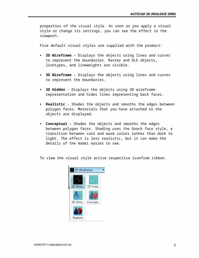
To view the visual style active respective iconfrom ribbon.
2.0 Creating surfaces
A mesh represents an object's surface using planar facets. The mesh density, or number of facets, is defined in terms of a matrix of M and N vertices, similar to a grid consisting of columns and rows. M and N specify the column and row
KUMAT2011 [email protected] 4
AUTOCAD 3D (REALEASE 2009)
position, respectively, of any given vertex. You can create meshes in both 2D and 3D, but they are used primarily for 3D.
Use meshes if you need hiding, shading, and rendering capabilities that wireframes don't provide but do not need the physical properties that solids provide (mass, weight, center of gravity, and so on). Meshes are also useful if you want to create geometry with unusual mesh patterns, such as a 3D topographical model of mountainous terrain.
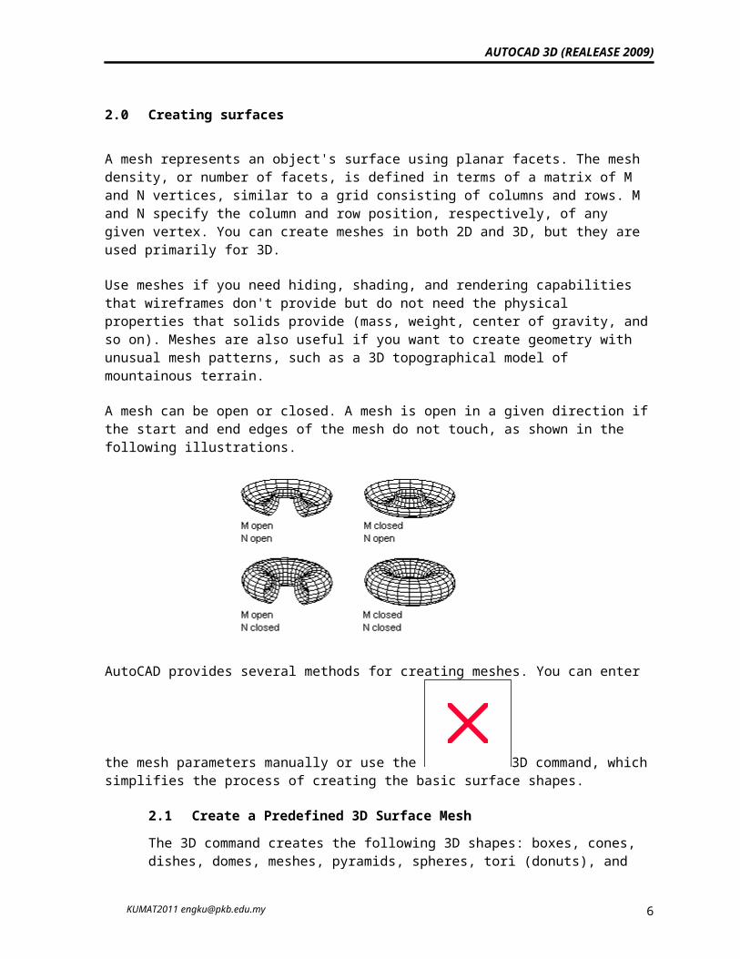
A mesh can be open or closed. A mesh is open in a given direction if the start and end edges of the mesh do not touch, as shown in the following illustrations.
AutoCAD provides several methods for creating meshes. You can enter the mesh
parameters manually or use the 3D command, which simplifies the process of creating the basic surface shapes.
2.1 Create a Predefined 3D Surface Mesh The 3D command creates the following 3D shapes: boxes, cones, dishes, domes, meshes, pyramids, spheres, tori (donuts), and wedges. These are
meshes that are displayed as wireframes until you use HIDE,
RENDER, or SHADEMODE.
KUMAT2011 [email protected] 5
AUTOCAD 3D (REALEASE 2009)
To view the objects you are creating with the 3D command more clearly,
set a viewing direction with 3DORBIT, DVIEW, or
VPOINT. The procedures for creating 3D shapes are similar to those for creating 3D solids.
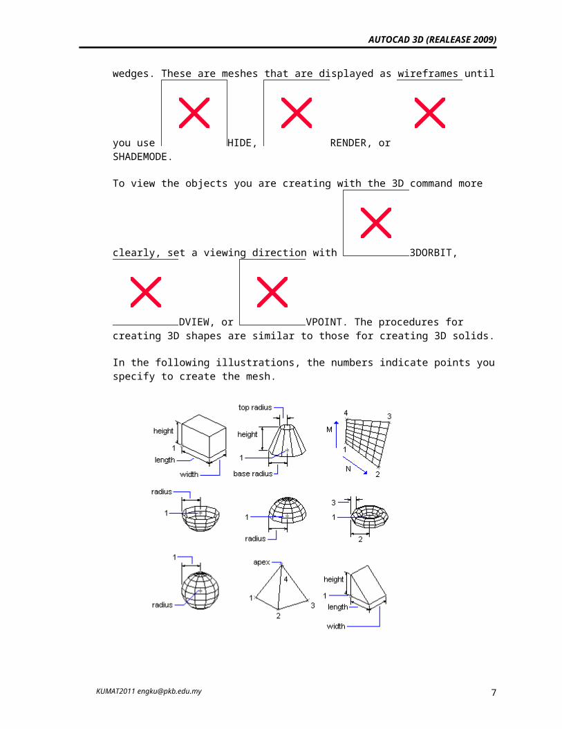
In the following illustrations, the numbers indicate points you specify to create the mesh.
2.2 Create a Rectangular Mesh
KUMAT2011 [email protected] 6
AUTOCAD 3D (REALEASE 2009)
With the 3DMESH command, you can create polygon meshes that are open in both the M and N directions (similar to the X and Y axes of
an XY plane). You can close the meshes with PEDIT. You can use 3DMESH to construct very irregular surfaces. In most cases, you can use 3DMESH in conjunction with scripts or AutoLISP routines when you know the mesh points.
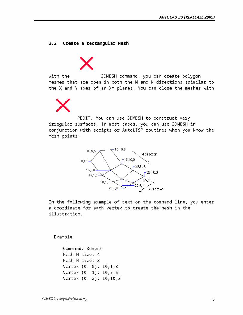
In the following example of text on the command line, you enter a coordinate for each vertex to create the mesh in the illustration.
Example
Command: 3dmesh Mesh M size: 4Mesh N size: 3 Vertex (0, 0): 10,1,3 Vertex (0, 1): 10,5,5 Vertex (0, 2): 10,10,3 Vertex (1, 0): 15,1,0 Vertex (1, 1): 15,5,0 Vertex (1, 2): 15,10,0 Vertex (2, 0): 20,1,0 Vertex (2, 1): 20,5,–1 Vertex (2, 2): 20,10,0 Vertex (3, 0): 25,1,0 Vertex (3, 1): 25,5,0 Vertex (3, 2): 25,10,0
KUMAT2011 [email protected] 7
AUTOCAD 3D (REALEASE 2009)
2.3 Create a Ruled Surface Mesh
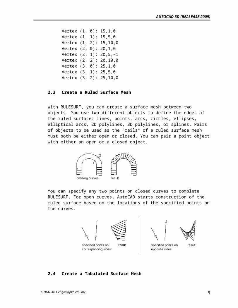
With RULESURF, you can create a surface mesh between two objects. You use two different objects to define the edges of the ruled surface: lines, points, arcs, circles, ellipses, elliptical arcs, 2D polylines, 3D polylines, or splines. Pairs of objects to be used as the "rails" of a ruled surface mesh must both be either open or closed. You can pair a point object with either an open or a closed object.
You can specify any two points on closed curves to complete RULESURF. For open curves, AutoCAD starts construction of the ruled surface based on the locations of the specified points on the curves.
2.4 Create a Tabulated Surface Mesh
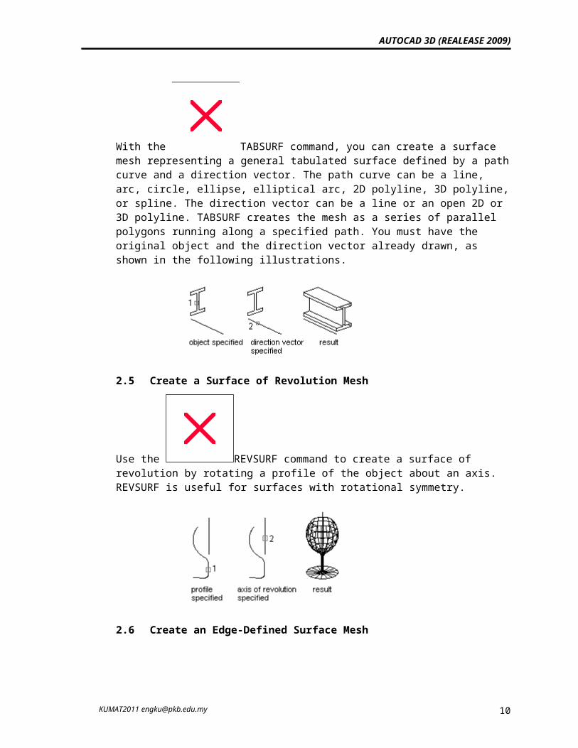
With the TABSURF command, you can create a surface mesh representing a general tabulated surface defined by a path curve and a direction vector. The path curve can be a line, arc, circle, ellipse, elliptical arc, 2D polyline, 3D polyline, or spline. The direction vector can be a line or an open 2D or 3D polyline. TABSURF creates the mesh as a series of parallel polygons running along a specified path. You must have the original object and the direction vector already drawn, as shown in the following illustrations.
KUMAT2011 [email protected] 8
AUTOCAD 3D (REALEASE 2009)
2.5 Create a Surface of Revolution Mesh
Use the REVSURF command to create a surface of revolution by rotating a profile of the object about an axis. REVSURF is useful for surfaces with rotational symmetry.
2.6 Create an Edge-Defined Surface Mesh
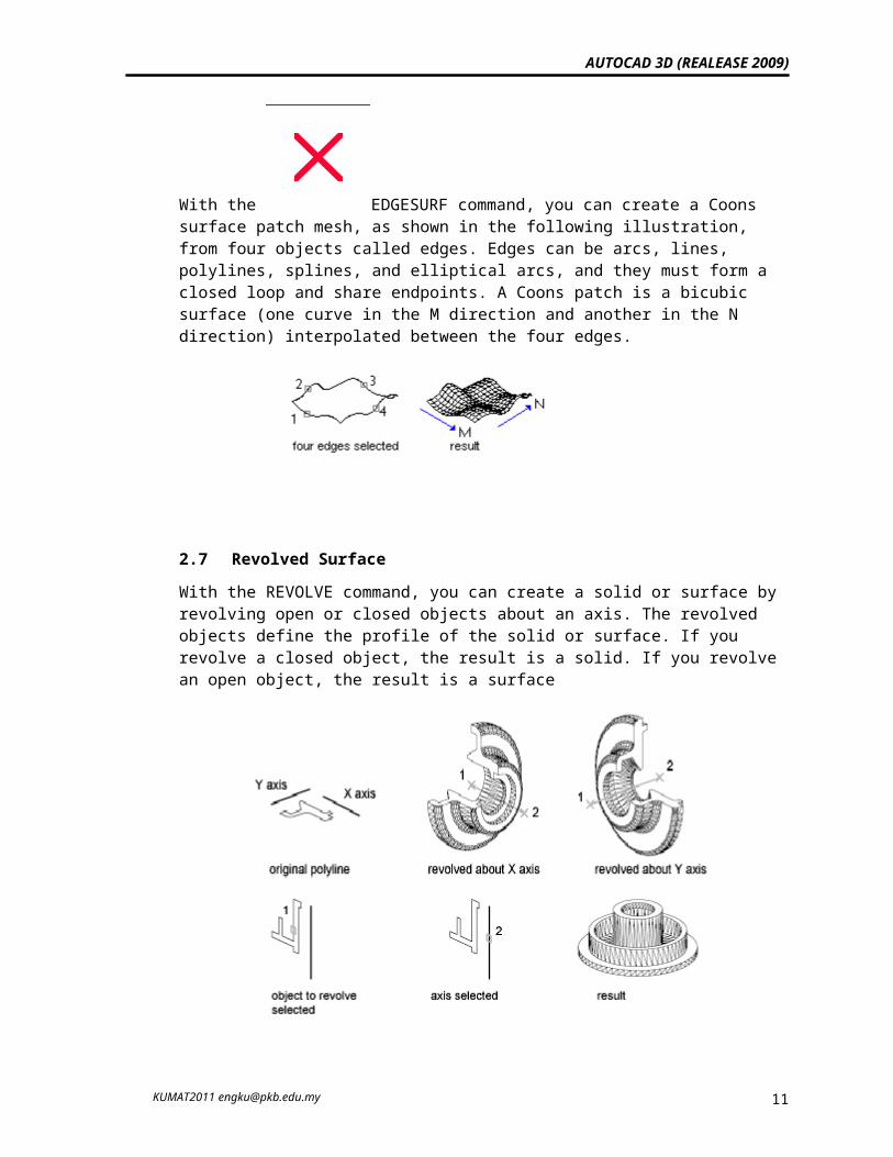
With the EDGESURF command, you can create a Coons surface patch mesh, as shown in the following illustration, from four objects called edges. Edges can be arcs, lines, polylines, splines, and elliptical arcs, and they must form a closed loop and share endpoints. A Coons patch is a bicubic surface (one curve in the M direction and another in the N direction) interpolated between the four edges.
KUMAT2011 [email protected] 9
AUTOCAD 3D (REALEASE 2009)
2.7 Revolved SurfaceWith the REVOLVE command, you can create a solid or surface by revolving open or closed objects about an axis. The revolved objects define the profile of the solid or surface. If you revolve a closed object, the result is a solid. If you revolve an open object, the result is a surface
To create solid using revolved command
Click Revolved Current wire frame density: SURFTAB1=0 SURFTAB2=0 Select object to revolve: select object Select object that defines the axis of revolution: select axis Specify start angle <0>: Specify included angle (+=ccw, -=cw) <360>:
Example 1
KUMAT2011 [email protected] 10
AUTOCAD 3D (REALEASE 2009)
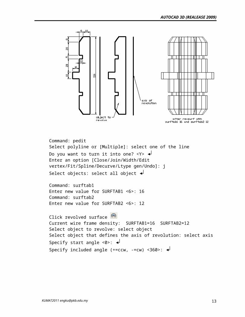
Draw object below and revolve with surftab1 = 16 and surftab2 = 12.
Command: peditSelect polyline or [Multiple]: select one of the lineDo you want to turn it into one? <Y> Enter an option [Close/Join/Width/Edit vertex/Fit/Spline/Decurve/Ltype gen/Undo]: jSelect objects: select all object
Command: surftab1Enter new value for SURFTAB1 <6>: 16Command: surftab2Enter new value for SURFTAB2 <6>: 12
Click revolved surface Current wire frame density: SURFTAB1=16 SURFTAB2=12Select object to revolve: select objectSelect object that defines the axis of revolution: select axis Specify start angle <0>: Specify included angle (+=ccw, -=cw) <360>:
Example 2
KUMAT2011 [email protected] 11
AUTOCAD 3D (REALEASE 2009)
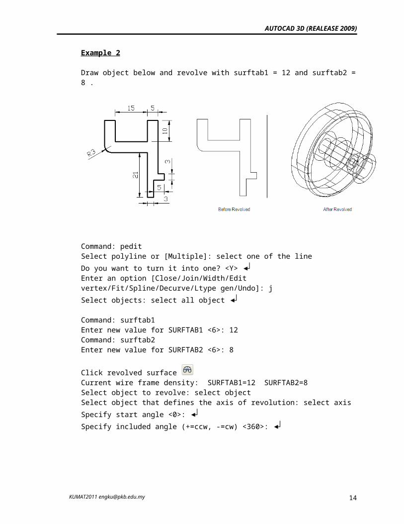
Draw object below and revolve with surftab1 = 12 and surftab2 = 8 .
Command: peditSelect polyline or [Multiple]: select one of the lineDo you want to turn it into one? <Y> Enter an option [Close/Join/Width/Edit vertex/Fit/Spline/Decurve/Ltype gen/Undo]: jSelect objects: select all object
Command: surftab1Enter new value for SURFTAB1 <6>: 12Command: surftab2Enter new value for SURFTAB2 <6>: 8
Click revolved surface Current wire frame density: SURFTAB1=12 SURFTAB2=8Select object to revolve: select objectSelect object that defines the axis of revolution: select axis Specify start angle <0>: Specify included angle (+=ccw, -=cw) <360>:
3.0 Creating 3D solid & wireframe
KUMAT2011 [email protected] 12
AUTOCAD 3D (REALEASE 2009)
A solid object represents the entire volume of an object. Solids are the most informationally complete and least ambiguous of the 3d modeling types. Complex solid shapes are also easier to construct and edit than wireframes and meshes. You create solids from one of the basic solid shapes of box, cone, cylinder, sphere, torus, and wedge or by extruding a 2d object along a path or revolving a 2d object about an axis. Once you have created a solid in this manner, you can create more complex shapes by combining solids. You can join solids, subtract solids from each other, or find the common volume (overlapping portion) of solids.
Solids can be further modified by filleting, chamfering, or changing the color of their edges. Faces on solids are easily manipulated because they don't require you to draw any new geometry or perform boolean operations on the solid. Autocad also provides commands for slicing a solid into two pieces or obtaining the 2d cross section of a solid
3.1 Create a Solid Box You can use BOX to create a solid box. The base of the box is always parallel to the XY plane of the current UCS. The RECTANG or PLINE command creates a rectangle or closed polyline from which you can create a box using EXTRUDE. The 3D command creates a box shape defined by surfaces only.
Example 3
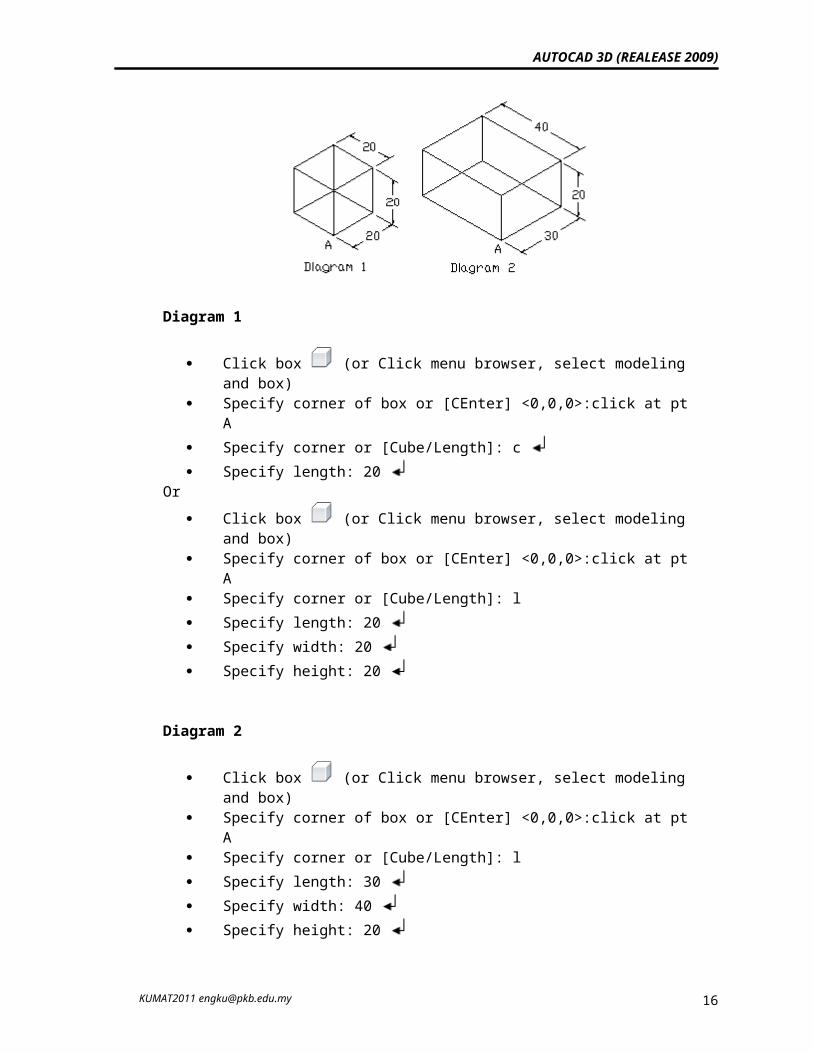
Active SW Isometric view and create a box below.
Diagram 1
Click box (or Click menu browser, select modeling and box) Specify corner of box or [CEnter] <0,0,0>:click at pt A Specify corner or [Cube/Length]: c Specify length: 20
KUMAT2011 [email protected] 13
AUTOCAD 3D (REALEASE 2009)
Or Click box (or Click menu browser, select modeling and box) Specify corner of box or [CEnter] <0,0,0>:click at pt A Specify corner or [Cube/Length]: l Specify length: 20 Specify width: 20 Specify height: 20
Diagram 2
Click box (or Click menu browser, select modeling and box) Specify corner of box or [CEnter] <0,0,0>:click at pt A Specify corner or [Cube/Length]: l Specify length: 30 Specify width: 40 Specify height: 20
(Note : length is x axis , width is y axis and height is z axis)
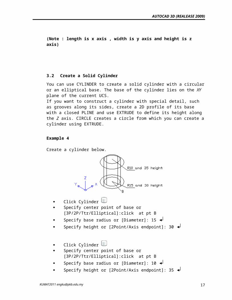
3.2 Create a Solid CylinderYou can use CYLINDER to create a solid cylinder with a circular or an elliptical base. The base of the cylinder lies on the XY plane of the current UCS. If you want to construct a cylinder with special detail, such as grooves along its sides, create a 2D profile of its base with a closed PLINE and use EXTRUDE to define its height along the Z axis. CIRCLE creates a circle from which you can create a cylinder using EXTRUDE.
Example 4
Create a cylinder below.
KUMAT2011 [email protected] 14
AUTOCAD 3D (REALEASE 2009)
Click Cylinder Specify center point of base or [3P/2P/Ttr/Elliptical]:click at pt B Specify base radius or [Diameter]: 15 Specify height or [2Point/Axis endpoint]: 30
Click Cylinder Specify center point of base or [3P/2P/Ttr/Elliptical]:click at pt B Specify base radius or [Diameter]: 10 Specify height or [2Point/Axis endpoint]: 35
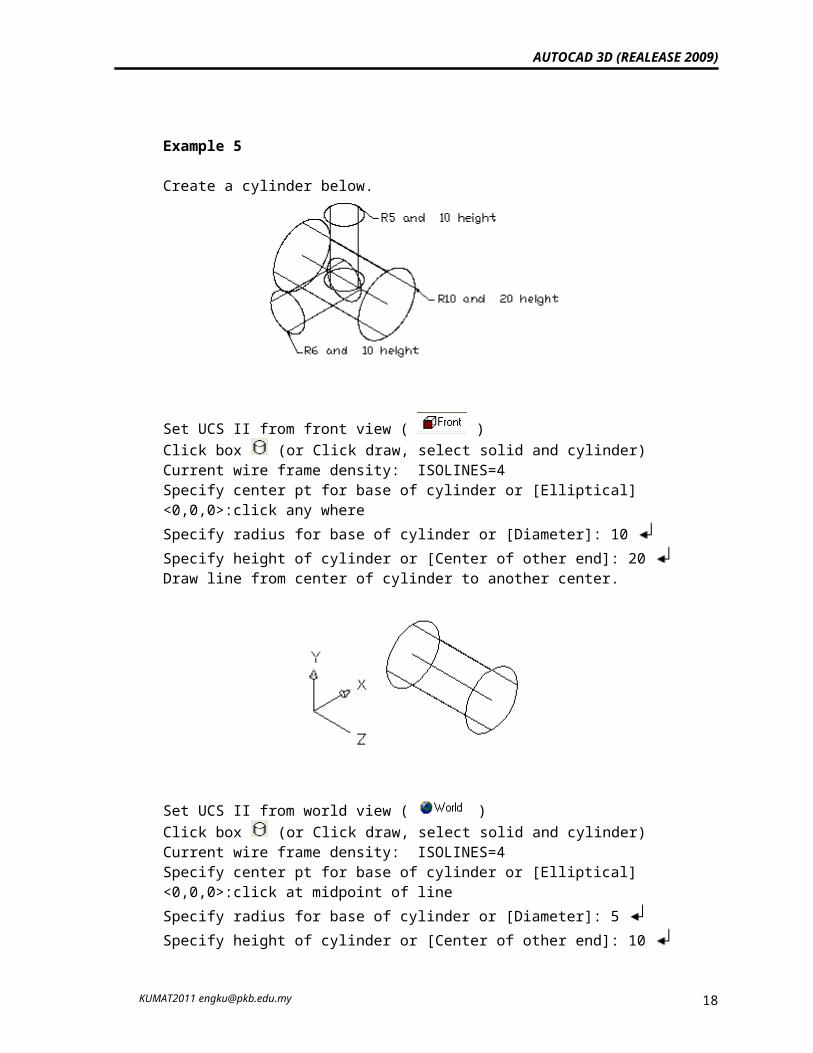
Example 5
Create a cylinder below.
Set UCS II from front view ( )Click box (or Click draw, select solid and cylinder)Current wire frame density: ISOLINES=4Specify center pt for base of cylinder or [Elliptical] <0,0,0>:click any whereSpecify radius for base of cylinder or [Diameter]: 10 Specify height of cylinder or [Center of other end]: 20 Draw line from center of cylinder to another center.
KUMAT2011 [email protected] 15
AUTOCAD 3D (REALEASE 2009)
Set UCS II from world view ( )Click box (or Click draw, select solid and cylinder)Current wire frame density: ISOLINES=4Specify center pt for base of cylinder or [Elliptical] <0,0,0>:click at midpoint of lineSpecify radius for base of cylinder or [Diameter]: 5 Specify height of cylinder or [Center of other end]: 10
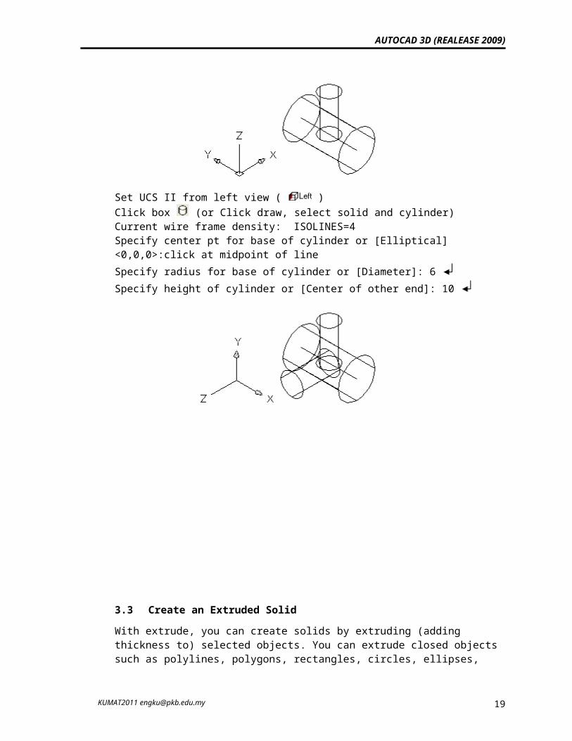
Set UCS II from left view ( )Click box (or Click draw, select solid and cylinder)Current wire frame density: ISOLINES=4Specify center pt for base of cylinder or [Elliptical] <0,0,0>:click at midpoint of lineSpecify radius for base of cylinder or [Diameter]: 6 Specify height of cylinder or [Center of other end]: 10
3.3 Create an Extruded Solid
KUMAT2011 [email protected] 16
AUTOCAD 3D (REALEASE 2009)
With extrude, you can create solids by extruding (adding thickness to) selected objects. You can extrude closed objects such as polylines, polygons, rectangles, circles, ellipses, closed splines, donuts, and regions. You cannot extrude 3D objects, objects contained within a block, polylines that have crossing or intersecting segments, or polylines that are not closed. You can extrude an object along a path, or you can specify a height value and a tapered angle.
If you create a profile using lines or arcs, use the Join option of PEDIT to convert them to a single polyline object or make them into a region before you use extrude.
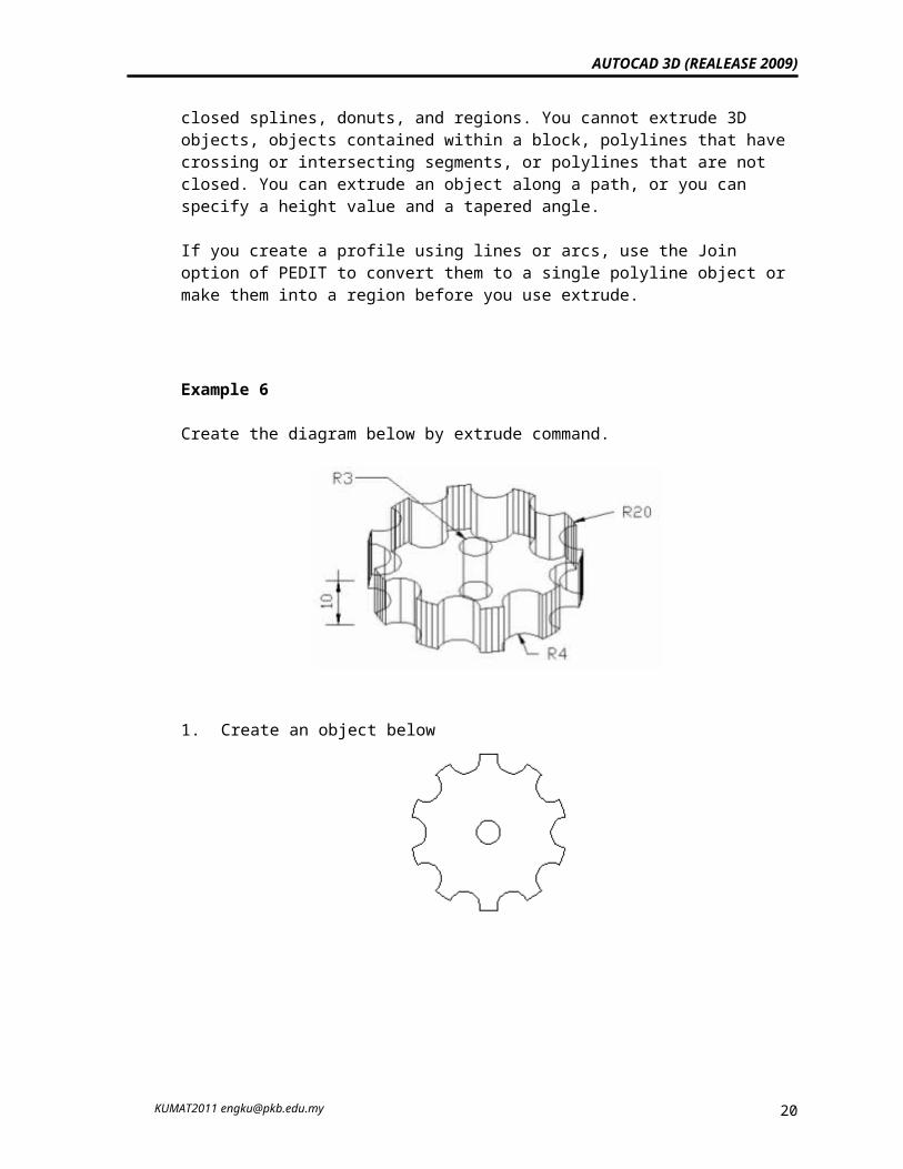
Example 6
Create the diagram below by extrude command.
1. Create an object below
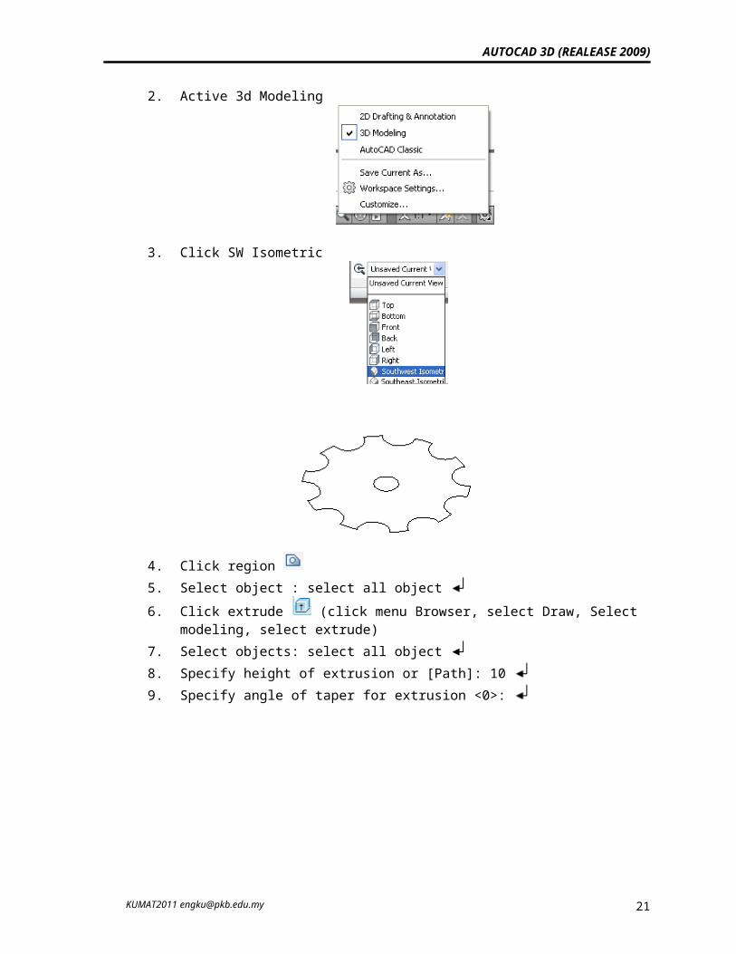
2. Active 3d Modeling
KUMAT2011 [email protected] 17
AUTOCAD 3D (REALEASE 2009)
3. Click SW Isometric
4. Click region 5. Select object : select all object 6. Click extrude (click menu Browser, select Draw, Select modeling,
select extrude)7. Select objects: select all object 8. Specify height of extrusion or [Path]: 10 9. Specify angle of taper for extrusion <0>:
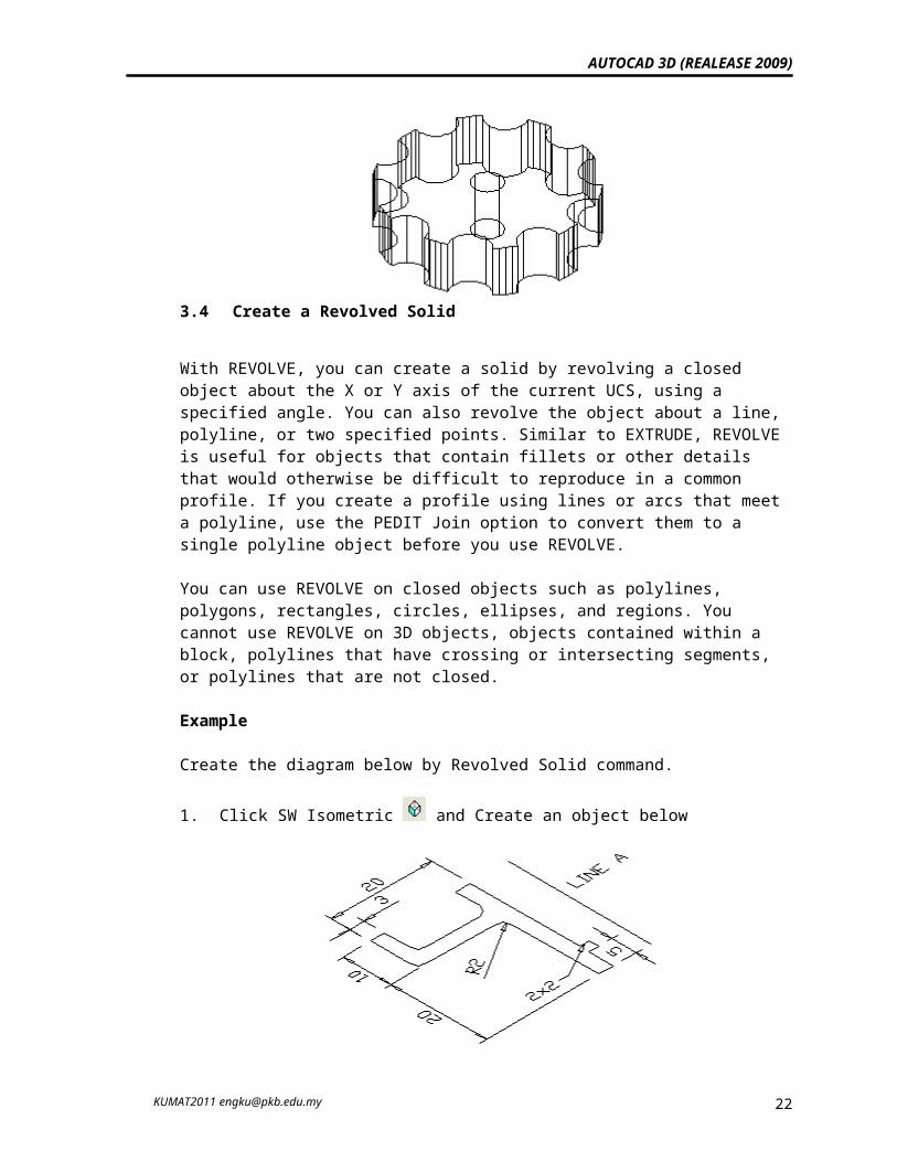
3.4 Create a Revolved Solid
KUMAT2011 [email protected] 18
AUTOCAD 3D (REALEASE 2009)
With REVOLVE, you can create a solid by revolving a closed object about the X or Y axis of the current UCS, using a specified angle. You can also revolve the object about a line, polyline, or two specified points. Similar to EXTRUDE, REVOLVE is useful for objects that contain fillets or other details that would otherwise be difficult to reproduce in a common profile. If you create a profile using lines or arcs that meet a polyline, use the PEDIT Join option to convert them to a single polyline object before you use REVOLVE.
You can use REVOLVE on closed objects such as polylines, polygons, rectangles, circles, ellipses, and regions. You cannot use REVOLVE on 3D objects, objects contained within a block, polylines that have crossing or intersecting segments, or polylines that are not closed.
Example
Create the diagram below by Revolved Solid command.
1. Click SW Isometric and Create an object below
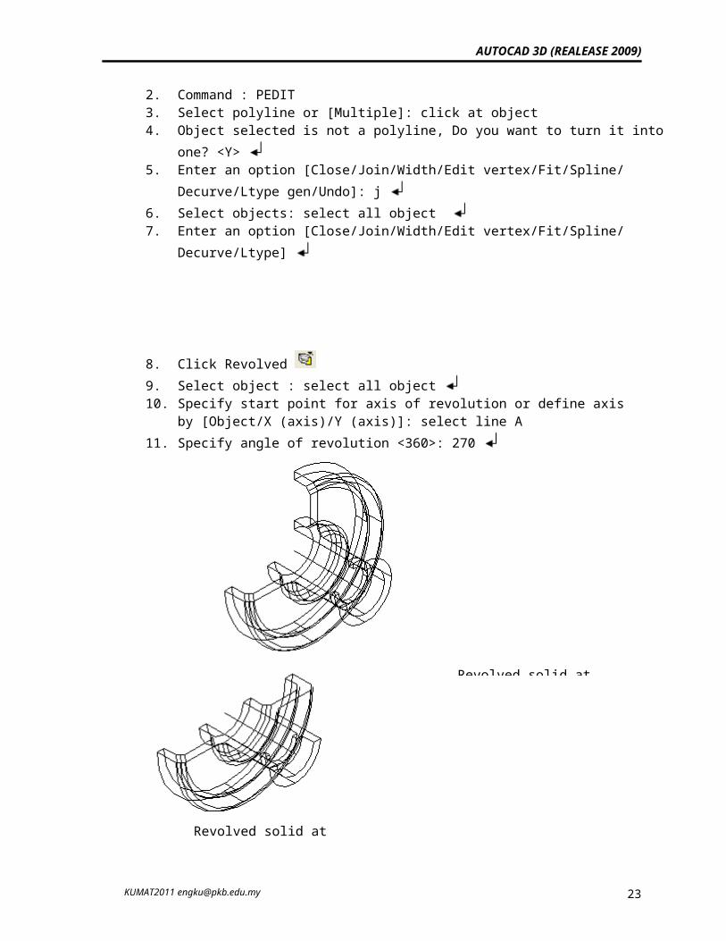
2. Command : PEDIT3. Select polyline or [Multiple]: click at object 4. Object selected is not a polyline, Do you want to turn it into one? <Y> 5. Enter an option [Close/Join/Width/Edit vertex/Fit/Spline/ Decurve/Ltype
gen/Undo]: j 6. Select objects: select all object 7. Enter an option [Close/Join/Width/Edit vertex/Fit/Spline/
Decurve/Ltype]
8. Click Revolved 9. Select object : select all object
KUMAT2011 [email protected] 19
AUTOCAD 3D (REALEASE 2009)
10. Specify start point for axis of revolution or define axis by [Object/X (axis)/Y (axis)]: select line A
11. Specify angle of revolution <360>: 270
4.0 Editing 3D solidYou can edit your solid object by extruding, moving, rotating, offsetting, tapering, deleting, copying it, or changing the color of the faces.
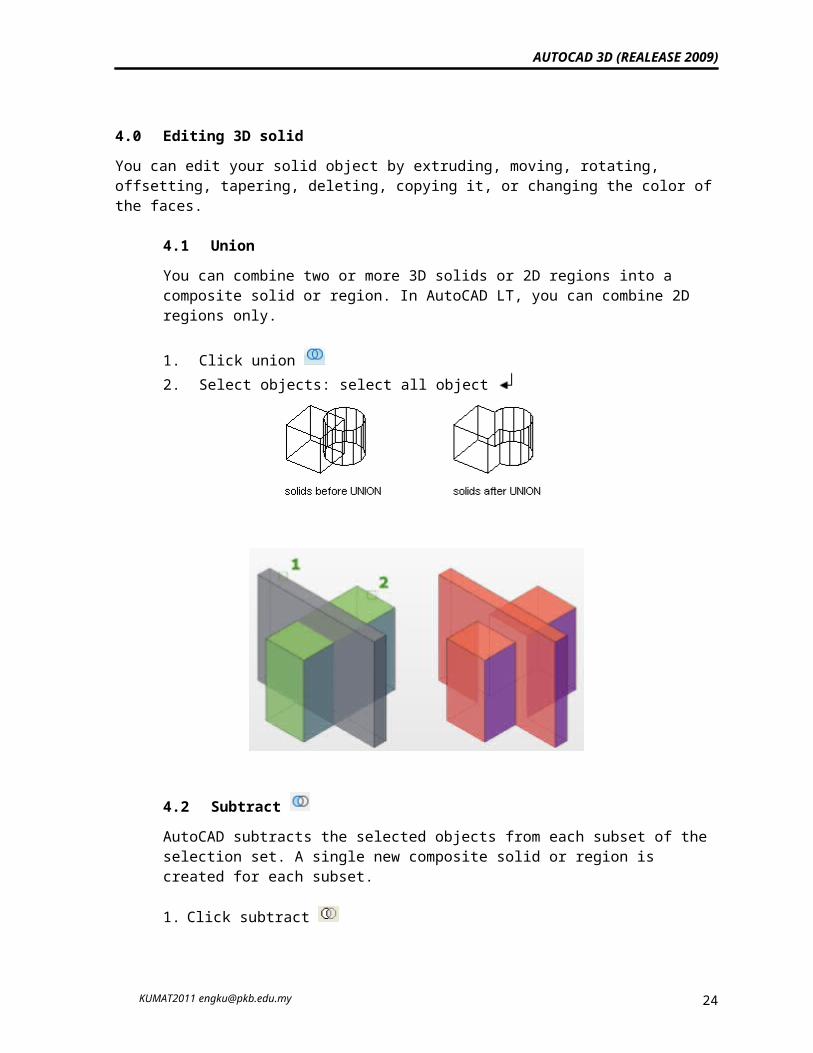
4.1 UnionYou can combine two or more 3D solids or 2D regions into a composite solid or region. In AutoCAD LT, you can combine 2D regions only.
1. Click union 2. Select objects: select all object
KUMAT2011 [email protected]
Revolved solid at 270o Revolved solid at
20
AUTOCAD 3D (REALEASE 2009)
4.2 Subtract AutoCAD subtracts the selected objects from each subset of the selection set. A single new composite solid or region is created for each subset.
1. Click subtract 2. Select solids and regions to subtract from ..: select rectangular 3. Select solids and regions to subtract .. : select cylinder
4.3 Extrude faces
You can extrude planar faces of a 3D solid along a path, or you can specify a height value and a tapered angle.
To extrude a face on a solid object 1. From the Ribbon, Solids Editing, choose Extrude Faces. 2. Select the face to extrude (1). 3. Select additional faces or press ENTER to extrude. 4. Specify the height of extrusion. 5. Specify a taper angle. 6. Press ENTER to complete the command.
KUMAT2011 [email protected] 21
AUTOCAD 3D (REALEASE 2009)
1. From the Ribbon, Solids Editing, Extrude Faces. 2. Select the face to extrude (1). 3. Select additional faces or press ENTER to extrude. 4. Enter p (Path). 5. Select the object to use as the path (2). 6. Press ENTER to complete the command.
4.4 Color faces 1. From the Ribbon, Solids Editing, Select Color Faces. 2. Select the face whose color you want to change. 3. Select additional faces or press ENTER. 4. In the Select Color dialog box, select a color and choose OK. 5. Press ENTER to complete the command.
Exercise
KUMAT2011 [email protected] 22