Embed Size (px)
Citation preview
ACECOMS & AIT Solutions 1
2016
Asian Center for Engineering Computations and Software
Introduction to
ACECOMS & AIT Solutions 2
2016
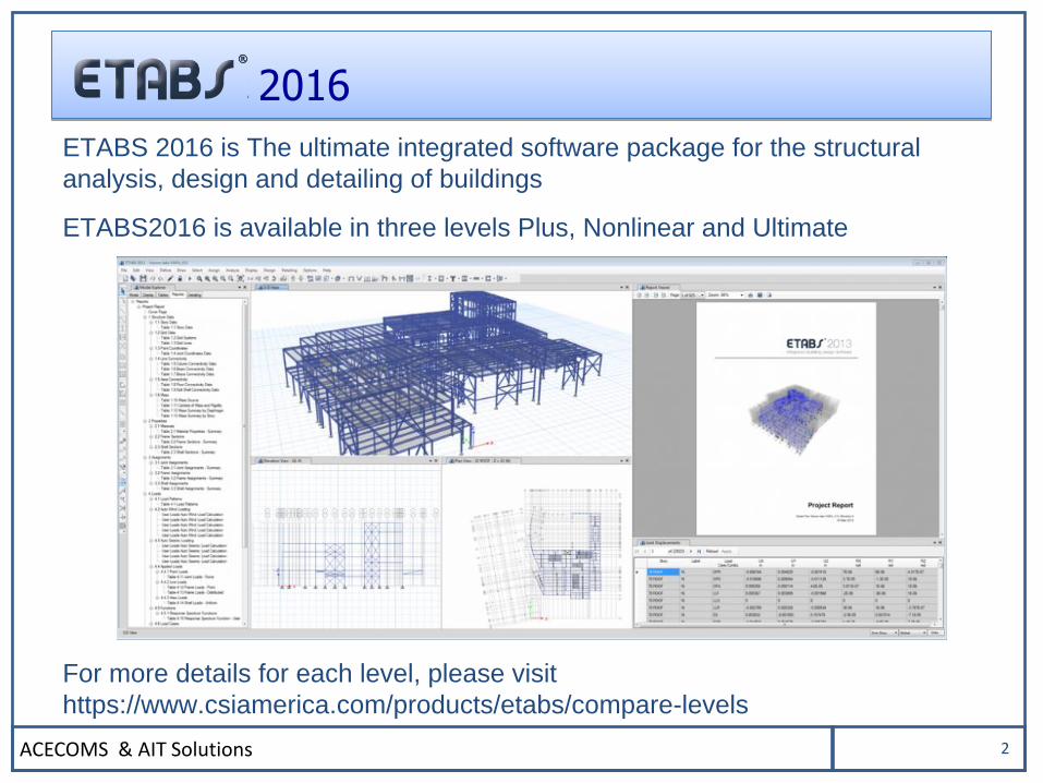
ETABS 2016 is The ultimate integrated software package for the structural
analysis, design and detailing of buildings
ETABS2016 is available in three levels Plus, Nonlinear and Ultimate
For more details for each level, please visit
https://www.csiamerica.com/products/etabs/compare-levels
ACECOMS & AIT Solutions 3
2016
BASIC CONCEPT
ACECOMS & AIT Solutions 4
2016
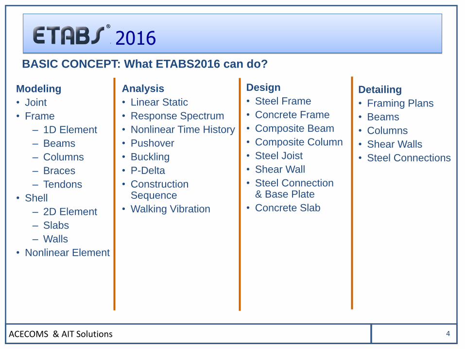
Analysis
• Linear Static
• Response Spectrum
• Nonlinear Time History
• Pushover
• Buckling
• P-Delta
• Construction Sequence
• Walking Vibration
Modeling
• Joint
• Frame
– 1D Element
– Beams
– Columns
– Braces
– Tendons
• Shell
– 2D Element
– Slabs
– Walls
• Nonlinear Element
Design
• Steel Frame
• Concrete Frame
• Composite Beam
• Composite Column
• Steel Joist
• Shear Wall
• Steel Connection& Base Plate
• Concrete Slab
BASIC CONCEPT: What ETABS2016 can do?
Detailing
• Framing Plans
• Beams
• Columns
• Shear Walls
• Steel Connections
ACECOMS & AIT Solutions 5
2016
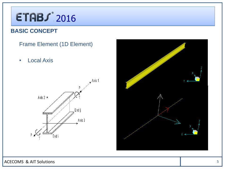
BASIC CONCEPT
Frame Element (1D Element)
• Local Axis
ACECOMS & AIT Solutions 6
2016
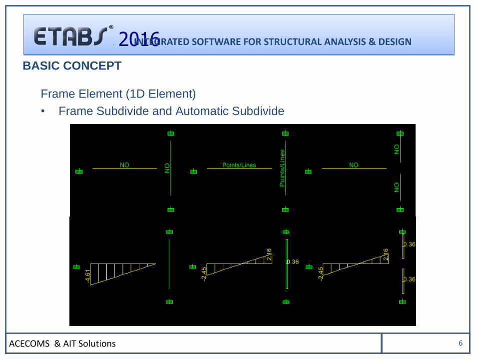
Frame Element (1D Element)
• Frame Subdivide and Automatic Subdivide
BASIC CONCEPT
INTEGRATED SOFTWARE FOR STRUCTURAL ANALYSIS & DESIGN
ACECOMS & AIT Solutions 7
2016
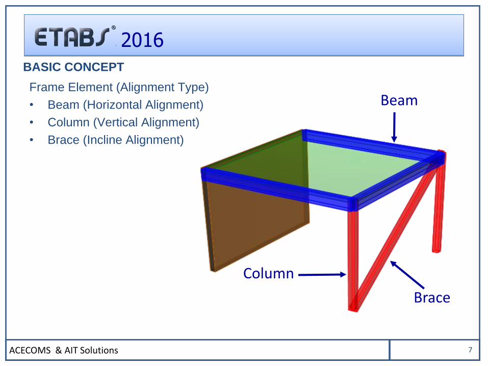
Frame Element (Alignment Type)
• Beam (Horizontal Alignment)
• Column (Vertical Alignment)
• Brace (Incline Alignment)
Column
Brace
Beam
BASIC CONCEPT
ACECOMS & AIT Solutions 8
2016
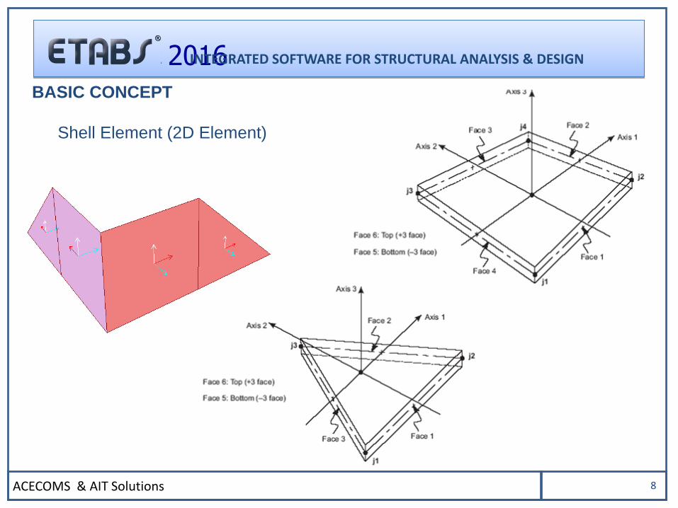
Shell Element (2D Element)
BASIC CONCEPT
INTEGRATED SOFTWARE FOR STRUCTURAL ANALYSIS & DESIGN
ACECOMS & AIT Solutions 9
2016
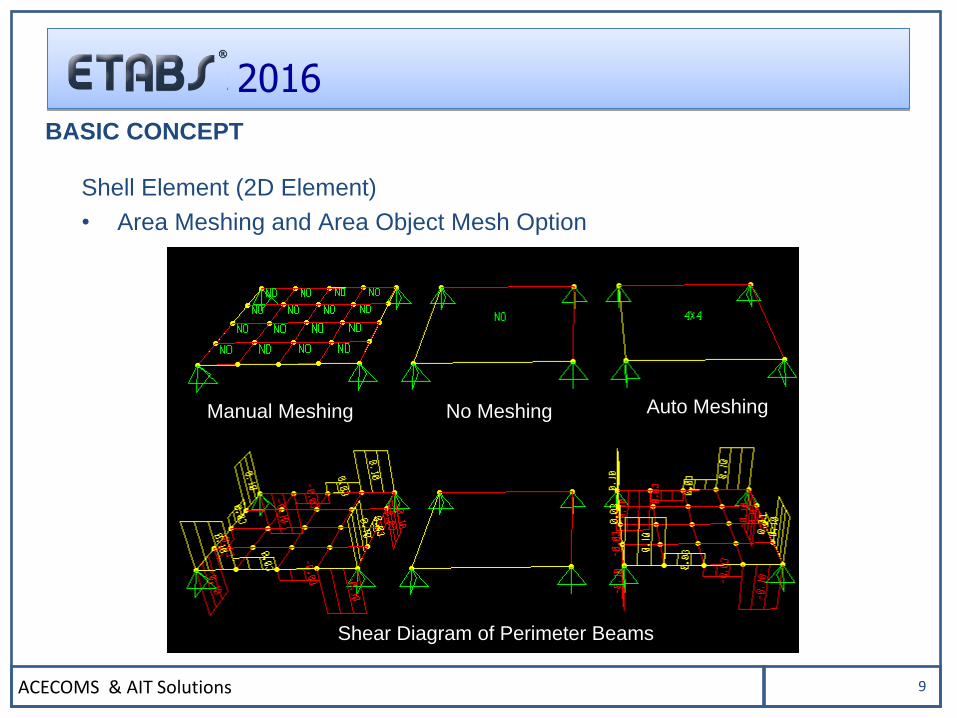
Shell Element (2D Element)
• Area Meshing and Area Object Mesh Option
BASIC CONCEPT
Manual Meshing No Meshing Auto Meshing
Shear Diagram of Perimeter Beams
ACECOMS & AIT Solutions 10
2016
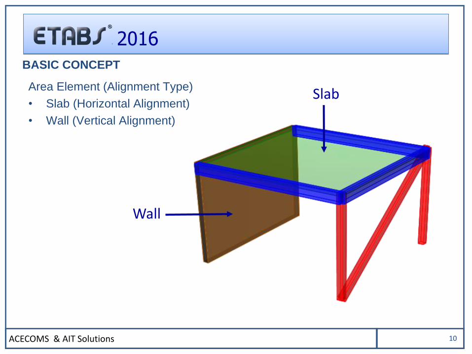
Area Element (Alignment Type)
• Slab (Horizontal Alignment)
• Wall (Vertical Alignment)
BASIC CONCEPT
Wall
Slab
ACECOMS & AIT Solutions 11
2016
USER INTERFACE
ACECOMS & AIT Solutions 12
2016
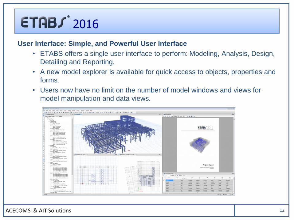
User Interface: Simple, and Powerful User Interface
• ETABS offers a single user interface to perform: Modeling, Analysis, Design,
Detailing and Reporting.
• A new model explorer is available for quick access to objects, properties and
forms.
• Users now have no limit on the number of model windows and views for
model manipulation and data views.
ACECOMS & AIT Solutions 13
2016
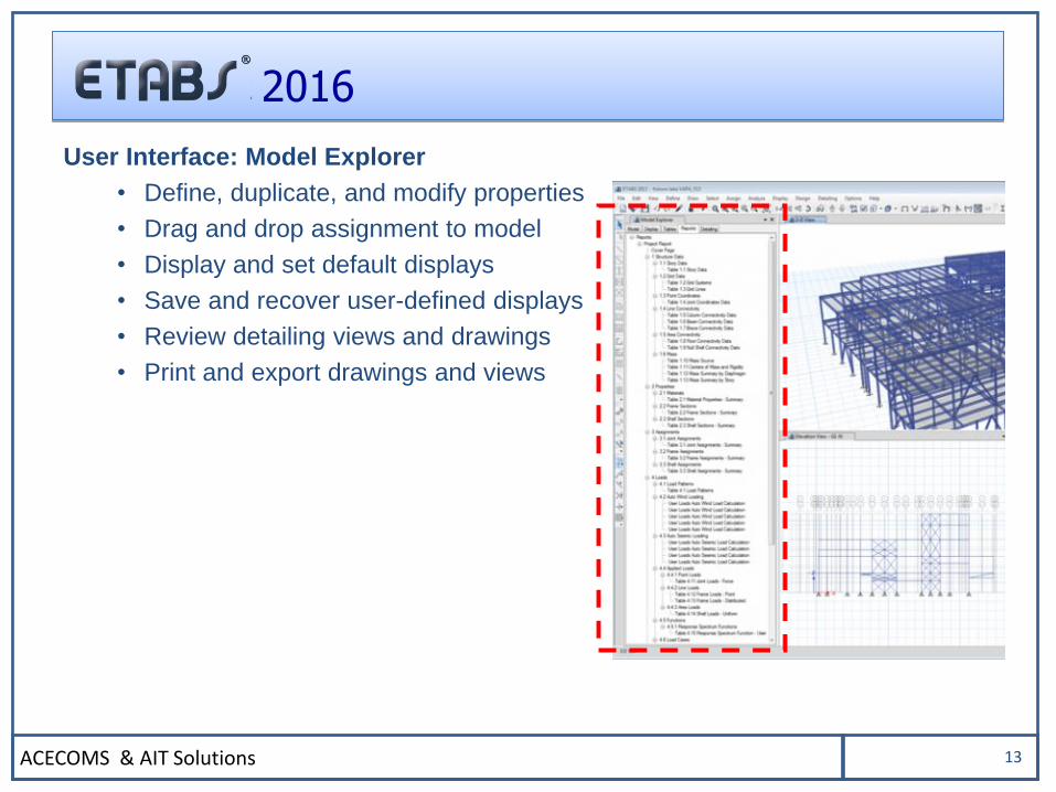
User Interface: Model Explorer
• Define, duplicate, and modify properties
• Drag and drop assignment to model
• Display and set default displays
• Save and recover user-defined displays
• Review detailing views and drawings
• Print and export drawings and views
ACECOMS & AIT Solutions 14
2016
MODELING
ACECOMS & AIT Solutions 15
2016
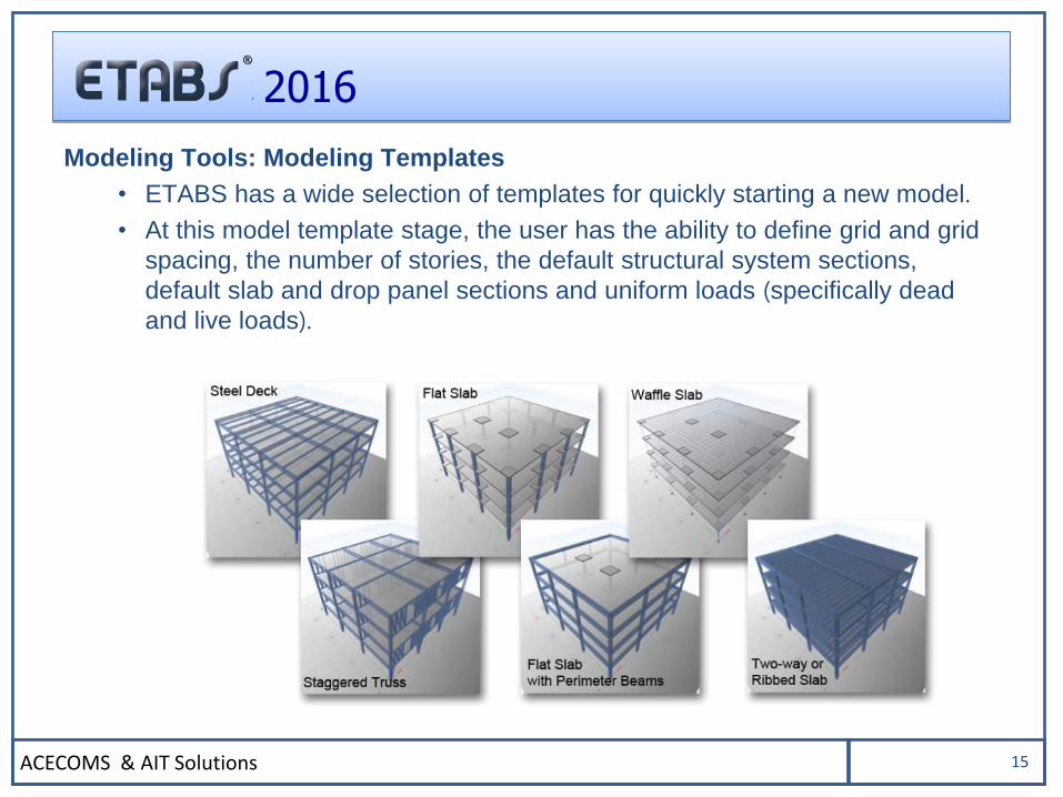
Modeling Tools: Modeling Templates
• ETABS has a wide selection of templates for quickly starting a new model.
• At this model template stage, the user has the ability to define grid and grid
spacing, the number of stories, the default structural system sections,
default slab and drop panel sections and uniform loads (specifically dead
and live loads).
ACECOMS & AIT Solutions 16
2016
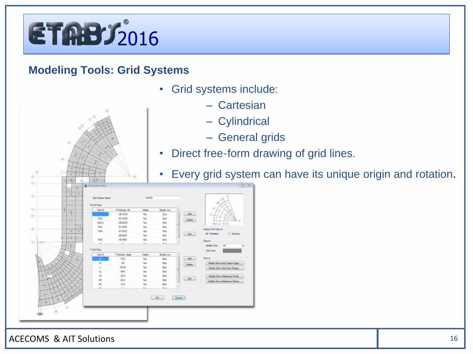
Modeling Tools: Grid Systems
• Grid systems include:
– Cartesian
– Cylindrical
– General grids
• Direct free-form drawing of grid lines.
• Every grid system can have its unique origin and rotation.
ACECOMS & AIT Solutions 17
2016
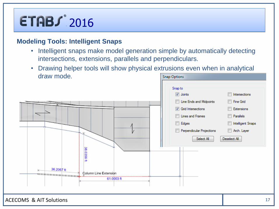
Modeling Tools: Intelligent Snaps
• Intelligent snaps make model generation simple by automatically detecting
intersections, extensions, parallels and perpendiculars.
• Drawing helper tools will show physical extrusions even when in analytical
draw mode.
ACECOMS & AIT Solutions 18
2016
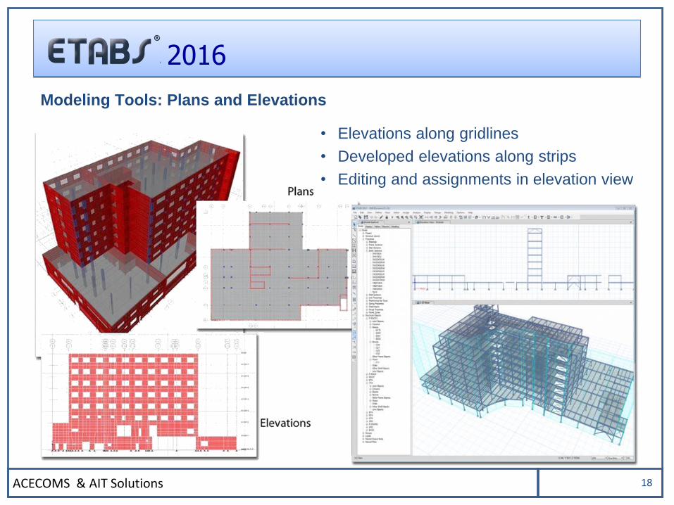
• Elevations along gridlines
• Developed elevations along strips
• Editing and assignments in elevation view
Modeling Tools: Plans and Elevations
ACECOMS & AIT Solutions 19
2016
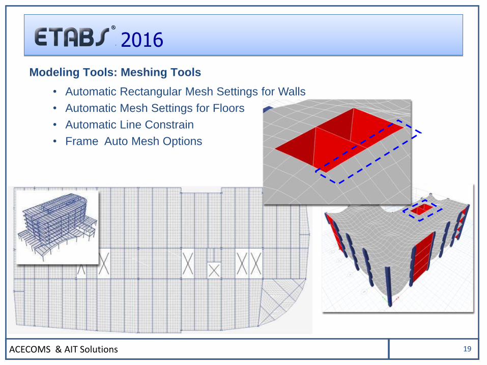
Modeling Tools: Meshing Tools
• Automatic Rectangular Mesh Settings for Walls
• Automatic Mesh Settings for Floors
• Automatic Line Constrain
• Frame Auto Mesh Options
ACECOMS & AIT Solutions 20
2016
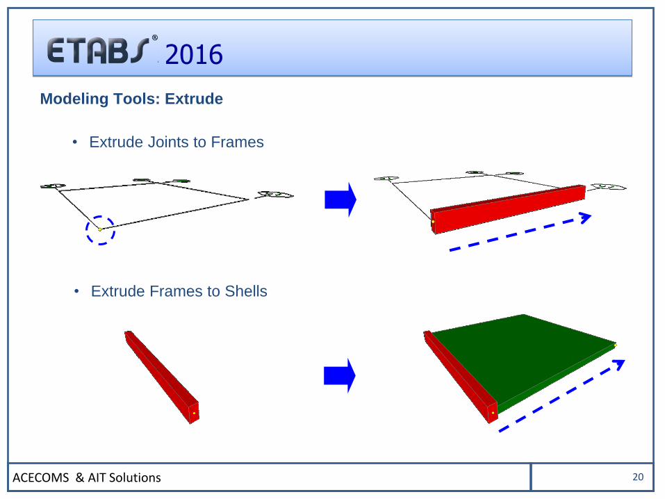
Modeling Tools: Extrude
• Extrude Joints to Frames
• Extrude Frames to Shells
ACECOMS & AIT Solutions 21
2016
BUILDING COMPONENTS
ACECOMS & AIT Solutions 22
2016
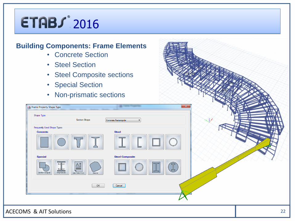
Building Components: Frame Elements
• Concrete Section
• Steel Section
• Steel Composite sections
• Special Section
• Non-prismatic sections
ACECOMS & AIT Solutions 23
2016
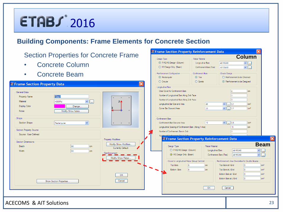
Section Properties for Concrete Frame
• Concrete Column
• Concrete Beam
Building Components: Frame Elements for Concrete Section
Column
Beam
ACECOMS & AIT Solutions 24
2016
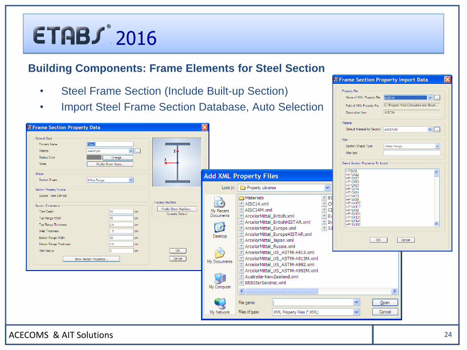
• Steel Frame Section (Include Built-up Section)
• Import Steel Frame Section Database, Auto Selection
Building Components: Frame Elements for Steel Section
ACECOMS & AIT Solutions 25
2016
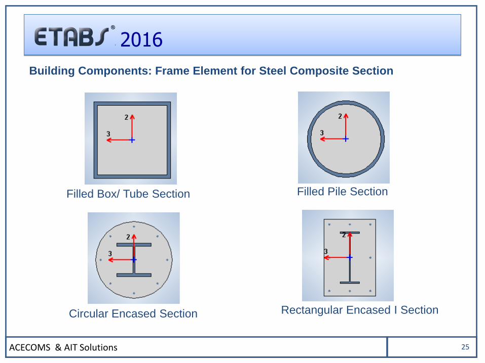
Building Components: Frame Element for Steel Composite Section
Filled Box/ Tube Section Filled Pile Section
Rectangular Encased I SectionCircular Encased Section
ACECOMS & AIT Solutions 26
2016
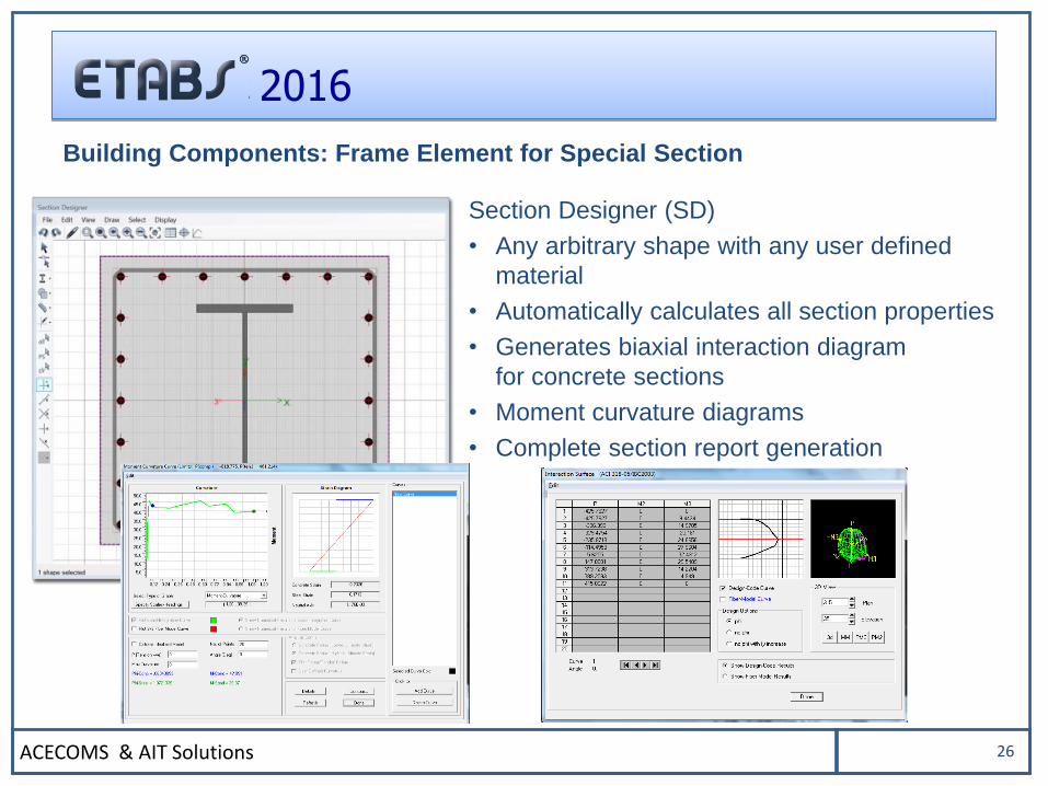
Building Components: Frame Element for Special Section
Section Designer (SD)
• Any arbitrary shape with any user defined
material
• Automatically calculates all section properties
• Generates biaxial interaction diagram
for concrete sections
• Moment curvature diagrams
• Complete section report generation
ACECOMS & AIT Solutions 27
2016
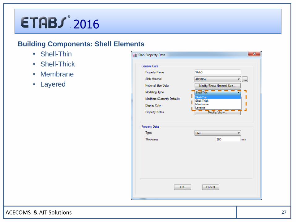
Building Components: Shell Elements
• Shell-Thin
• Shell-Thick
• Membrane
• Layered
ACECOMS & AIT Solutions 28
2016
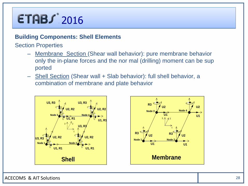
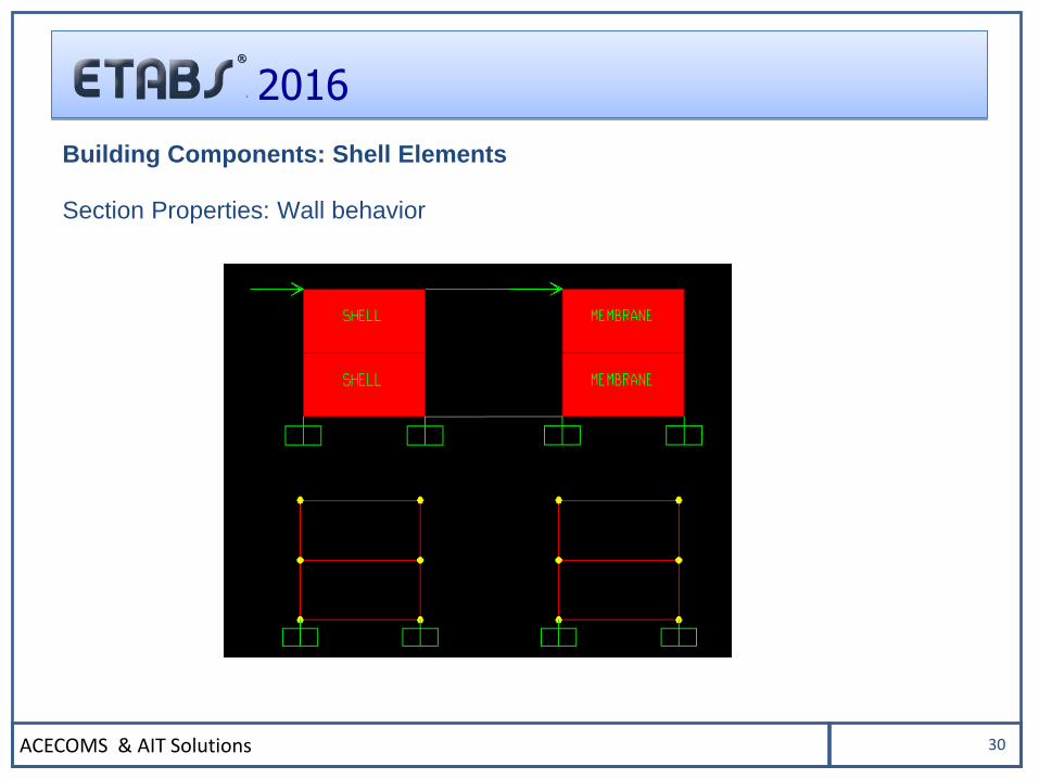
Section Properties
– Membrane Section (Shear wall behavior): pure membrane behavior
only the in-plane forces and the nor mal (drilling) moment can be sup
ported
– Shell Section (Shear wall + Slab behavior): full shell behavior, a
combination of membrane and plate behavior
Building Components: Shell Elements
Membrane
U1
Node 1
R3U2
U1
Node 3
R3U2
U1
Node 4
R3
U2
U1
Node 2
U2
3 2
1
1
23
U1, R1
Node 3
U3, R3
U2, R2
U1, R1
Node 1
U3, R3 U2, R2
U1, R1
Node 4
U3, R3
U2, R2
U1, R1
Node 2
U3, R3
U2, R2
Shell
ACECOMS & AIT Solutions 29
2016
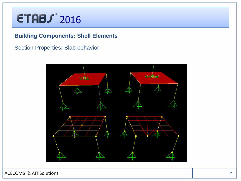
Section Properties: Slab behavior
Building Components: Shell Elements
ACECOMS & AIT Solutions 30
2016
Section Properties: Wall behavior
Building Components: Shell Elements
ACECOMS & AIT Solutions 31
2016
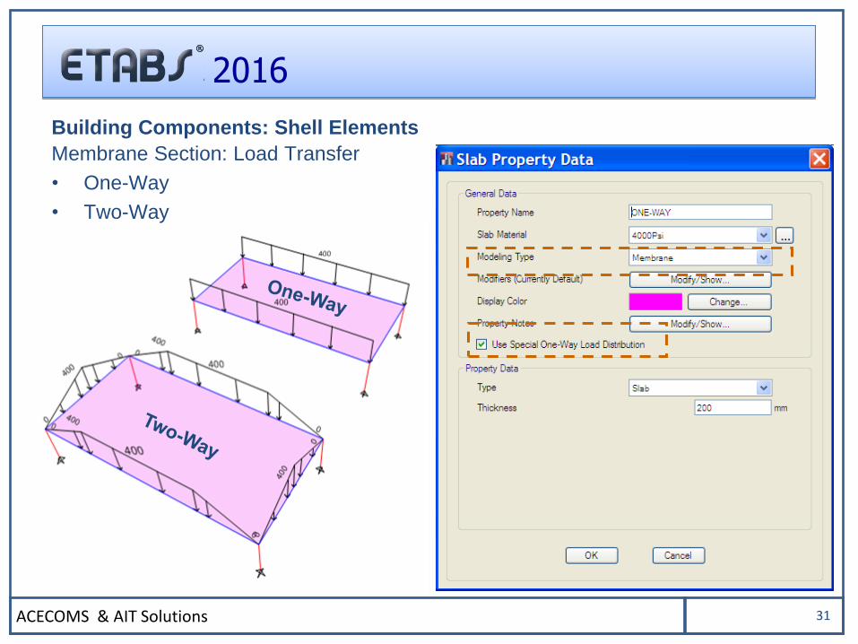
Membrane Section: Load Transfer
• One-Way
• Two-Way
Building Components: Shell Elements
ACECOMS & AIT Solutions 32
2016
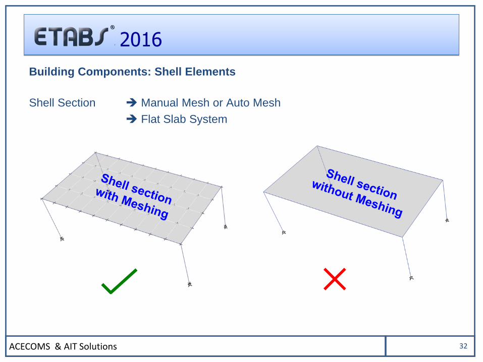
Shell Section Manual Mesh or Auto Mesh
Flat Slab System
Building Components: Shell Elements
ACECOMS & AIT Solutions 33
2016
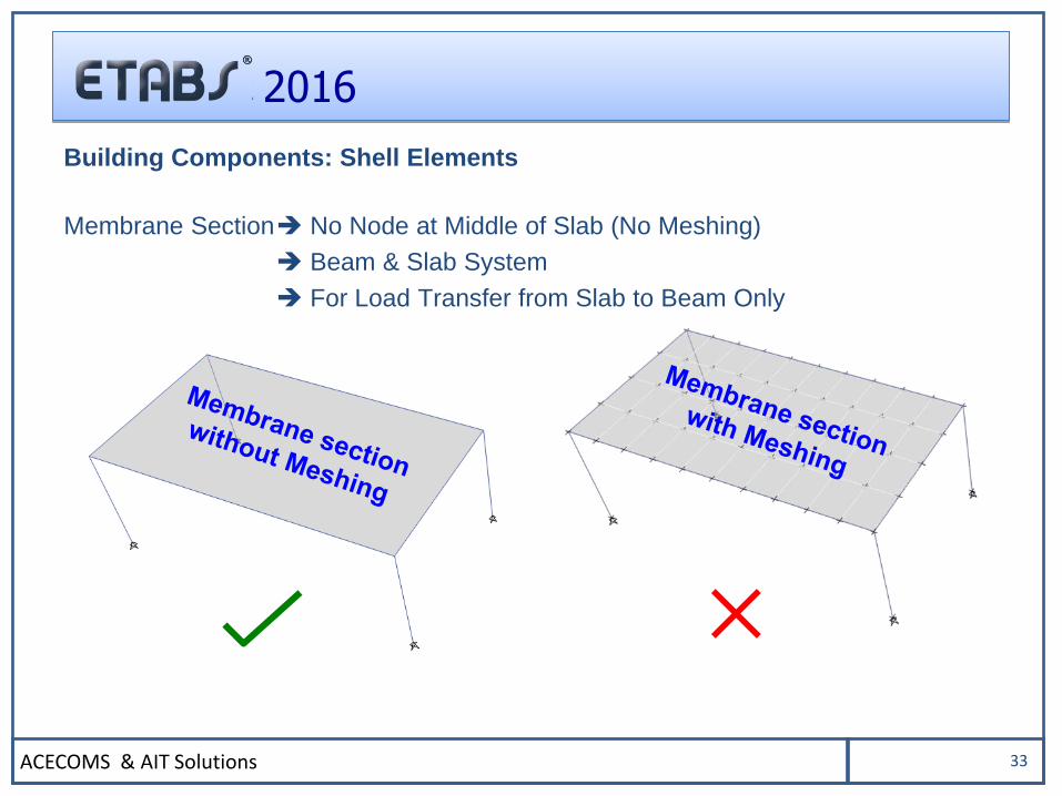
Membrane Section No Node at Middle of Slab (No Meshing)
Beam & Slab System
For Load Transfer from Slab to Beam Only
Building Components: Shell Elements
ACECOMS & AIT Solutions 34
2016
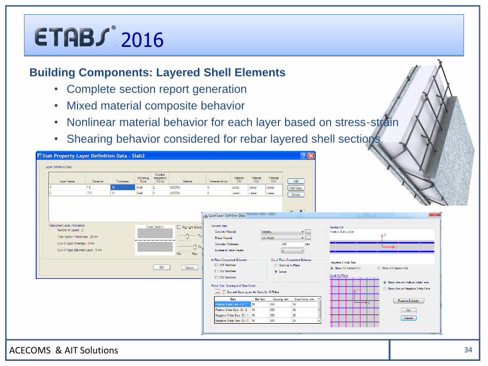
Building Components: Layered Shell Elements
• Complete section report generation
• Mixed material composite behavior
• Nonlinear material behavior for each layer based on stress-strain
• Shearing behavior considered for rebar layered shell sections.
ACECOMS & AIT Solutions 35
2016
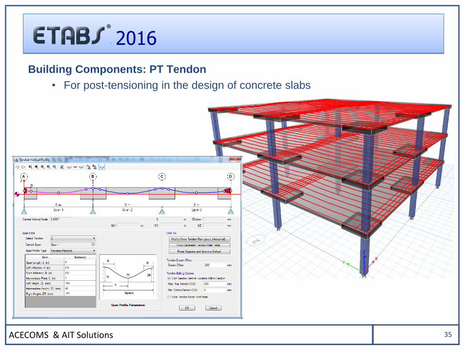
Building Components: PT Tendon
• For post-tensioning in the design of concrete slabs
ACECOMS & AIT Solutions 36
2016
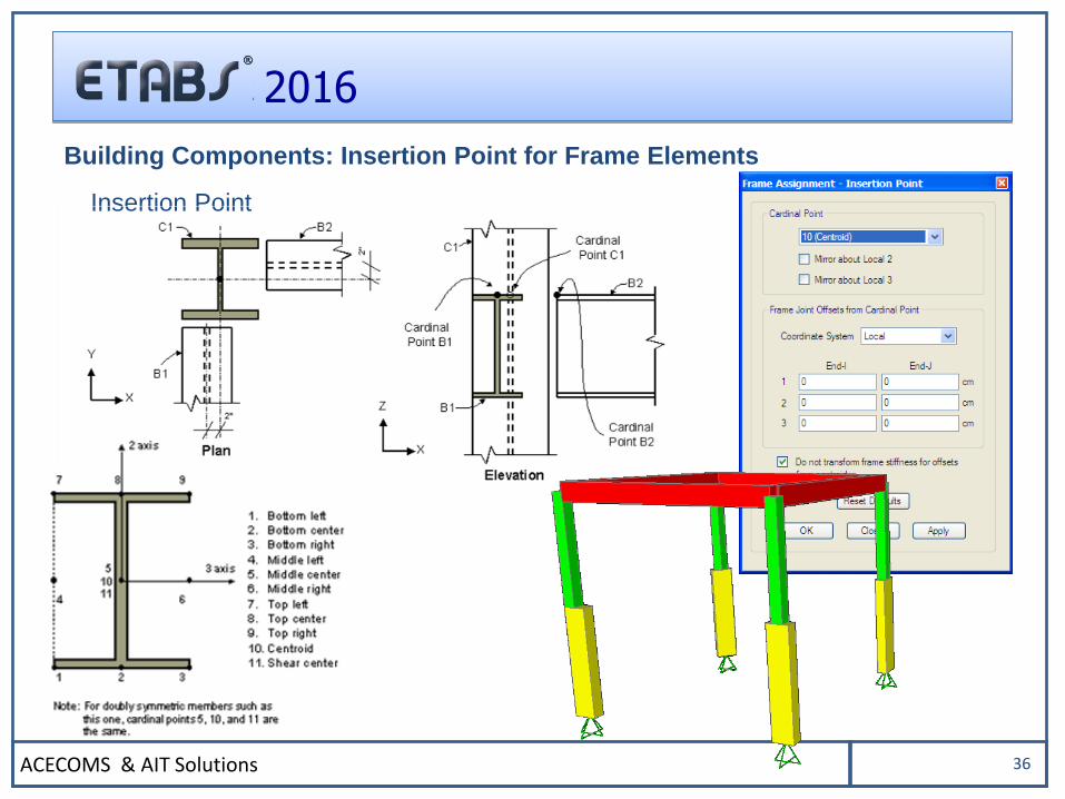
Insertion Point
Building Components: Insertion Point for Frame Elements
ACECOMS & AIT Solutions 37
2016
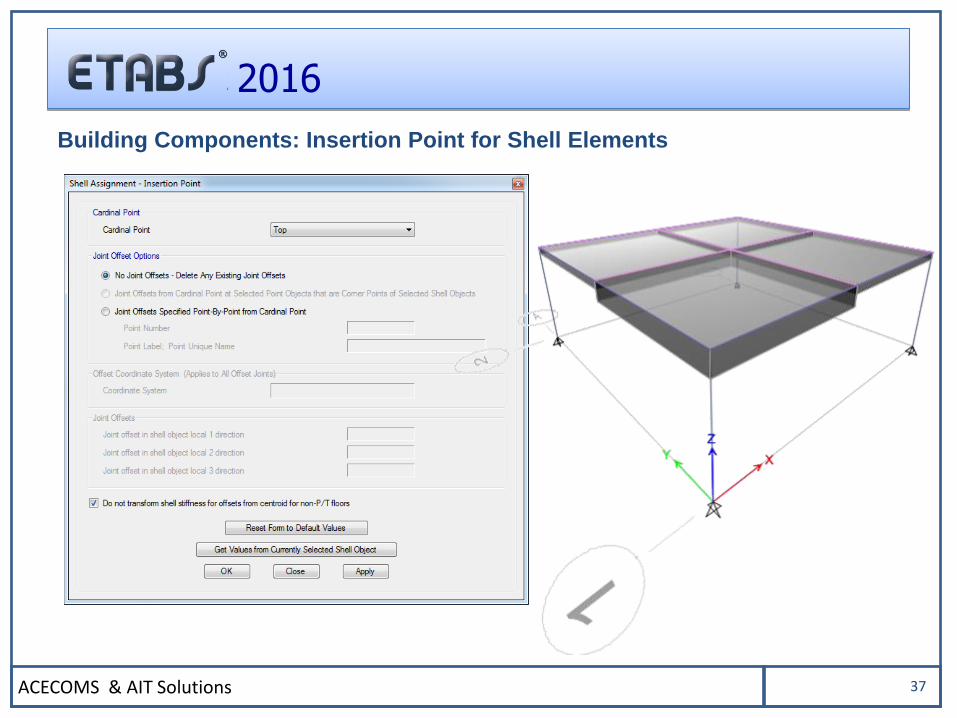
Building Components: Insertion Point for Shell Elements
ACECOMS & AIT Solutions 38
2016
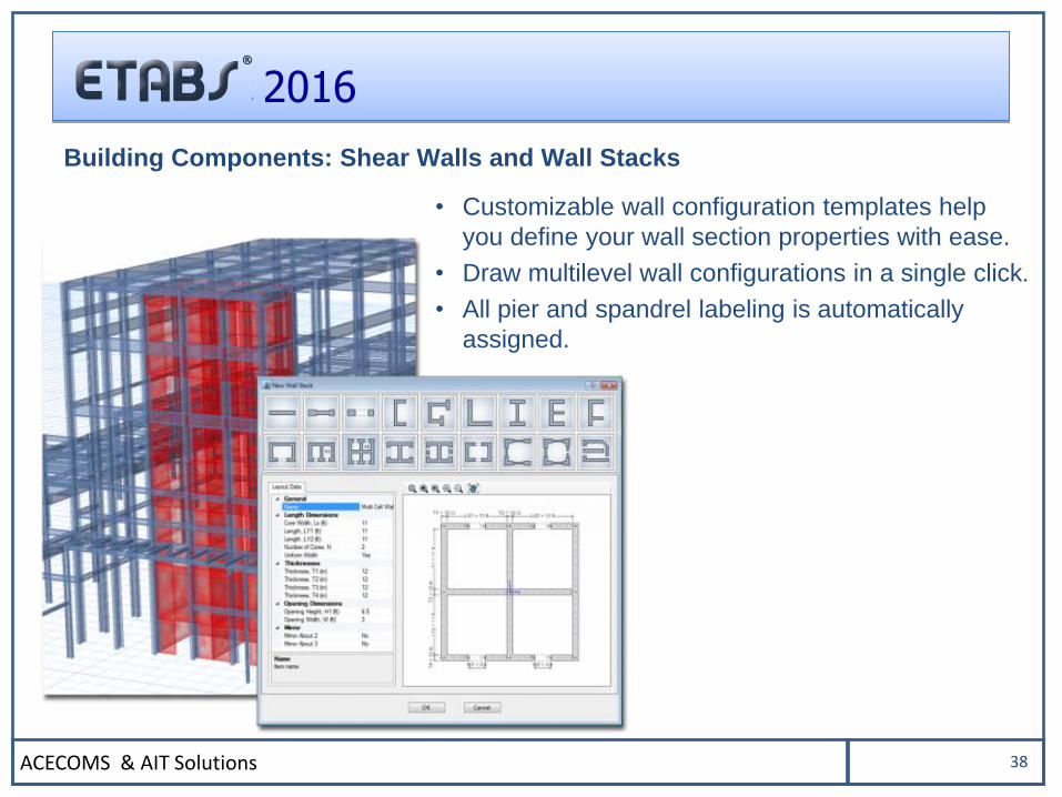
Building Components: Shear Walls and Wall Stacks
• Customizable wall configuration templates help
you define your wall section properties with ease.
• Draw multilevel wall configurations in a single click.
• All pier and spandrel labeling is automatically
assigned.
ACECOMS & AIT Solutions 39
2016
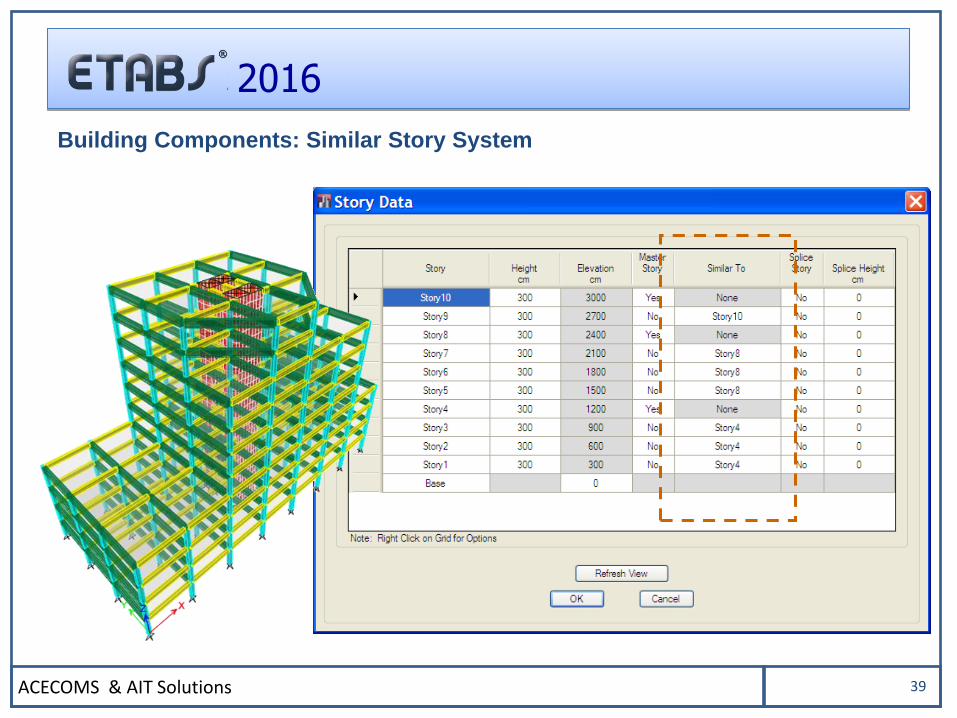
Building Components: Similar Story System
ACECOMS & AIT Solutions 40
2016
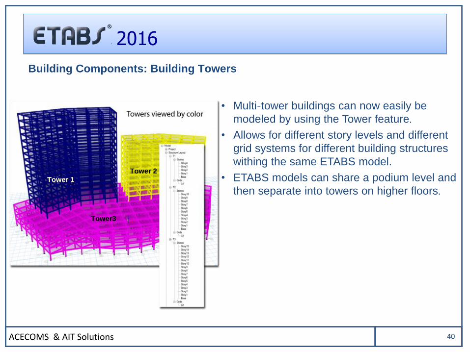
Building Components: Building Towers
• Multi-tower buildings can now easily be
modeled by using the Tower feature.
• Allows for different story levels and different
grid systems for different building structures
withing the same ETABS model.
• ETABS models can share a podium level and
then separate into towers on higher floors.Tower 1
Tower 2
Tower3
ACECOMS & AIT Solutions 41
2016
LOADING
ACECOMS & AIT Solutions 42
2016
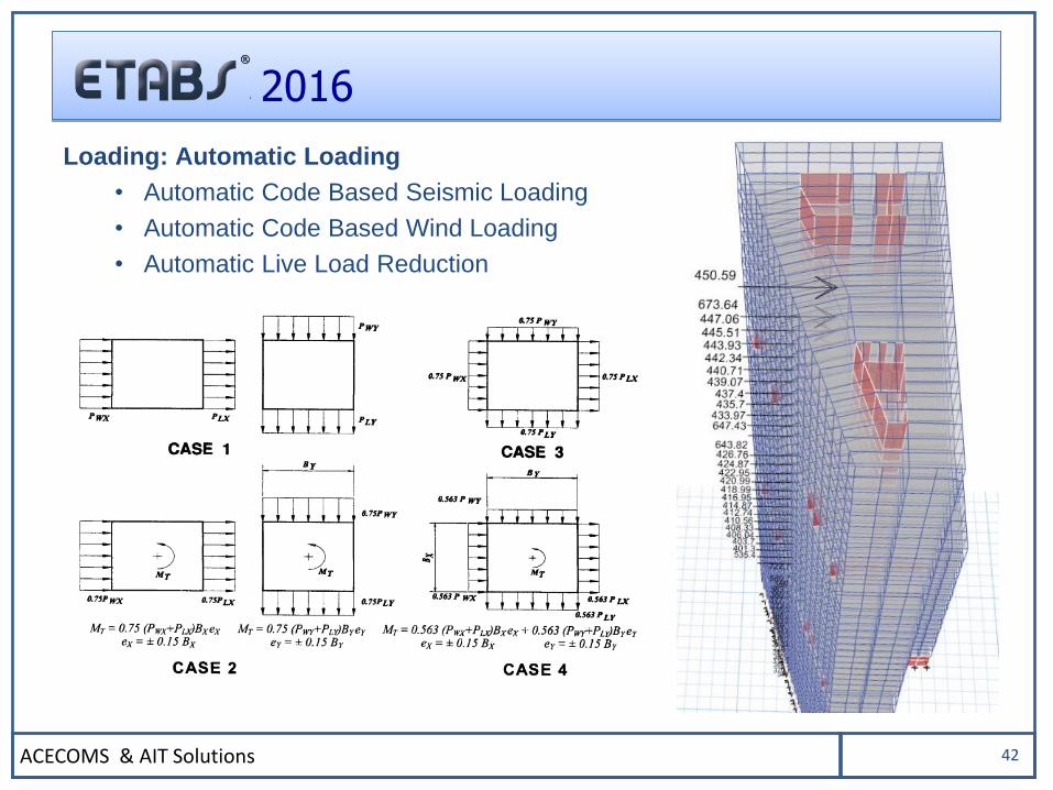
Loading: Automatic Loading
• Automatic Code Based Seismic Loading
• Automatic Code Based Wind Loading
• Automatic Live Load Reduction
ACECOMS & AIT Solutions 43
2016
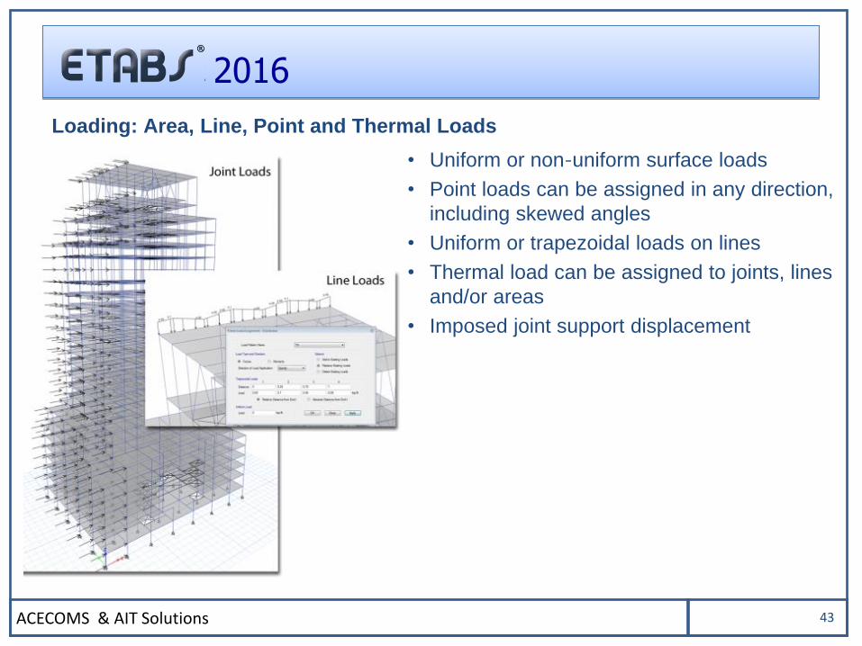
Loading: Area, Line, Point and Thermal Loads
• Uniform or non-uniform surface loads
• Point loads can be assigned in any direction,
including skewed angles
• Uniform or trapezoidal loads on lines
• Thermal load can be assigned to joints, lines
and/or areas
• Imposed joint support displacement
ACECOMS & AIT Solutions 44
2016
ANALYSIS
ACECOMS & AIT Solutions 45
2016
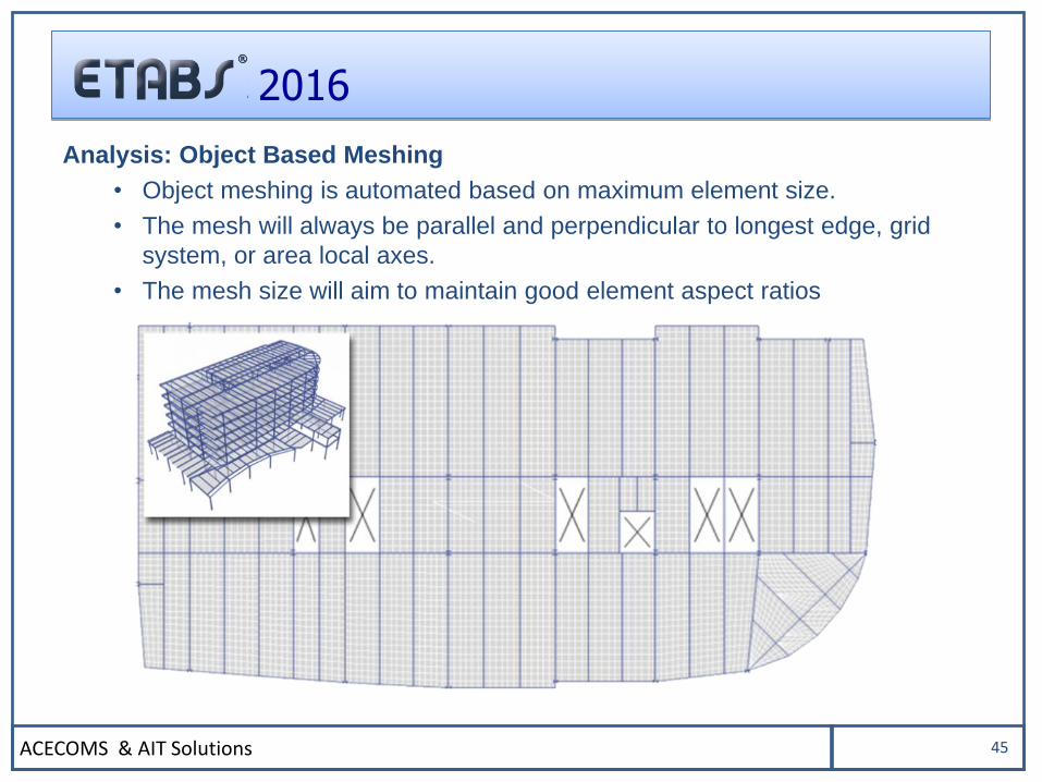
Analysis: Object Based Meshing
• Object meshing is automated based on maximum element size.
• The mesh will always be parallel and perpendicular to longest edge, grid
system, or area local axes.
• The mesh size will aim to maintain good element aspect ratios
ACECOMS & AIT Solutions 46
2016
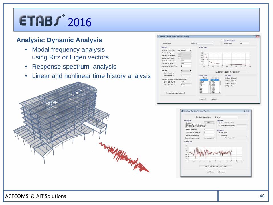
Analysis: Dynamic Analysis
• Modal frequency analysis
using Ritz or Eigen vectors
• Response spectrum analysis
• Linear and nonlinear time history analysis
ACECOMS & AIT Solutions 47
2016
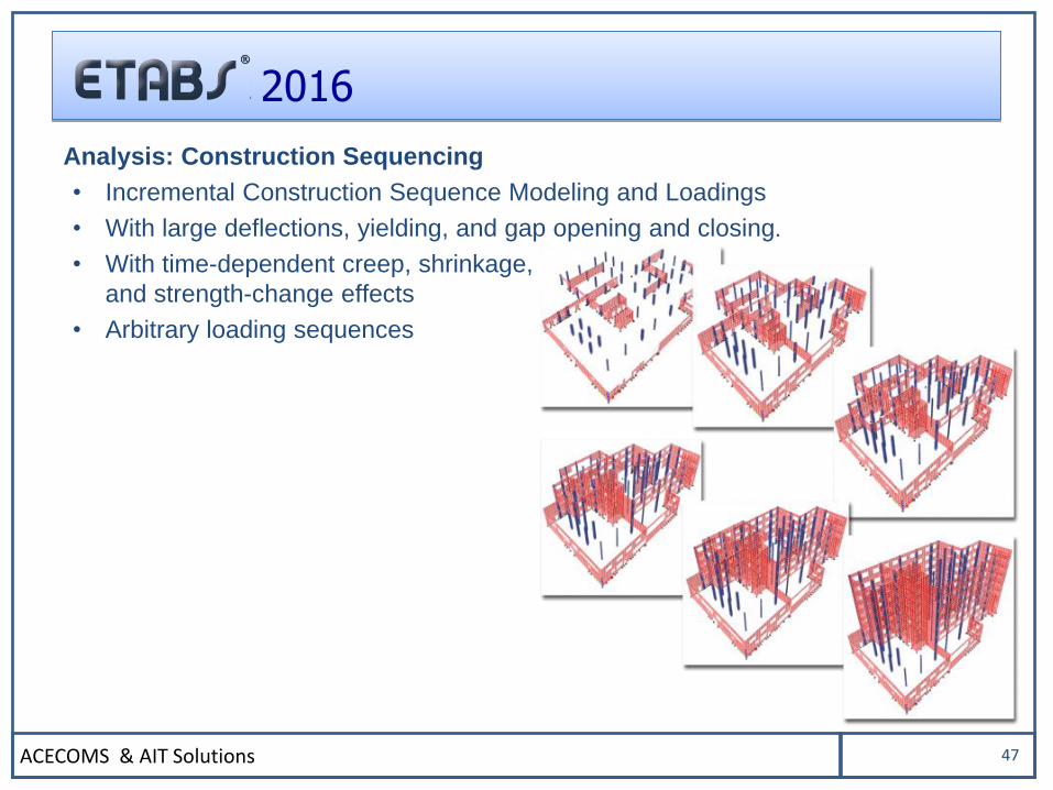
Analysis: Construction Sequencing
• Incremental Construction Sequence Modeling and Loadings
• With large deflections, yielding, and gap opening and closing.
• With time-dependent creep, shrinkage,
and strength-change effects
• Arbitrary loading sequences
ACECOMS & AIT Solutions 48
2016
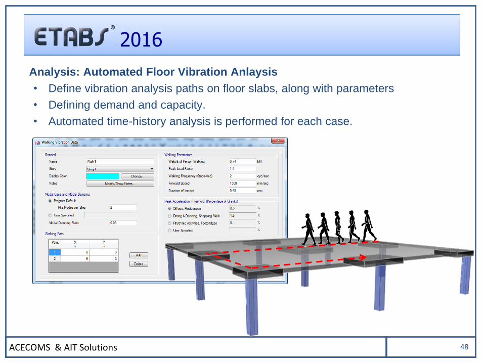
Analysis: Automated Floor Vibration Anlaysis
• Define vibration analysis paths on floor slabs, along with parameters
• Defining demand and capacity.
• Automated time-history analysis is performed for each case.
ACECOMS & AIT Solutions 49
2016
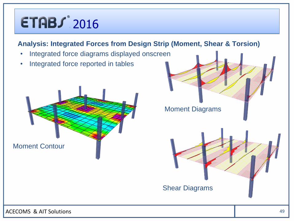
Analysis: Integrated Forces from Design Strip (Moment, Shear & Torsion)
• Integrated force diagrams displayed onscreen
• Integrated force reported in tables
Moment Diagrams
Shear Diagrams
Moment Contour
ACECOMS & AIT Solutions 50
2016
DESIGN
ACECOMS & AIT Solutions 51
2016
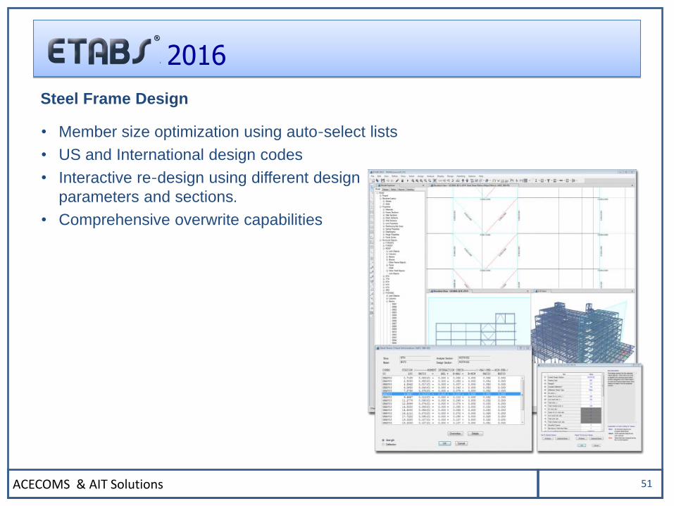
Steel Frame Design
• Member size optimization using auto-select lists
• US and International design codes
• Interactive re-design using different design
parameters and sections.
• Comprehensive overwrite capabilities
ACECOMS & AIT Solutions 52
2016
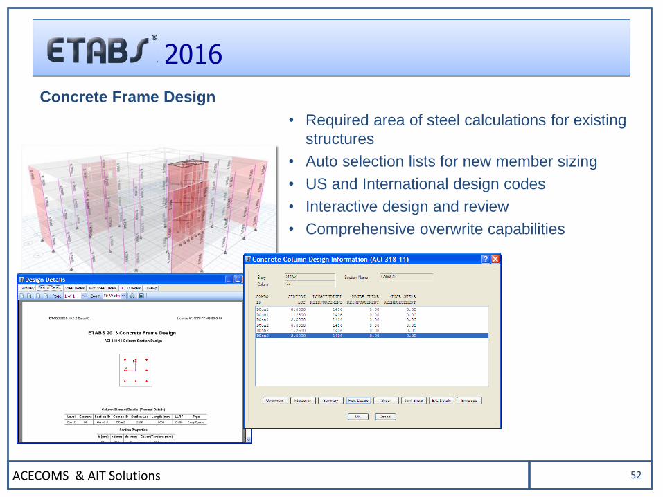
Concrete Frame Design
• Required area of steel calculations for existing
structures
• Auto selection lists for new member sizing
• US and International design codes
• Interactive design and review
• Comprehensive overwrite capabilities
ACECOMS & AIT Solutions 53
2016
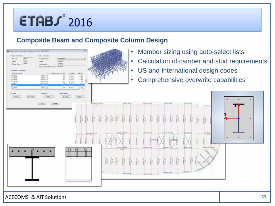
Composite Beam and Composite Column Design
• Member sizing using auto-select lists
• Calculation of camber and stud requirements
• US and International design codes
• Comprehensive overwrite capabilities
ACECOMS & AIT Solutions 54
2016
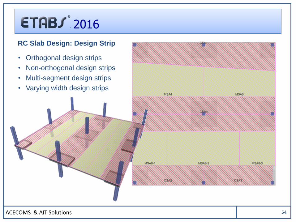
RC Slab Design: Design Strip
• Orthogonal design strips
• Non-orthogonal design strips
• Multi-segment design strips
• Varying width design strips
ACECOMS & AIT Solutions 55
2016
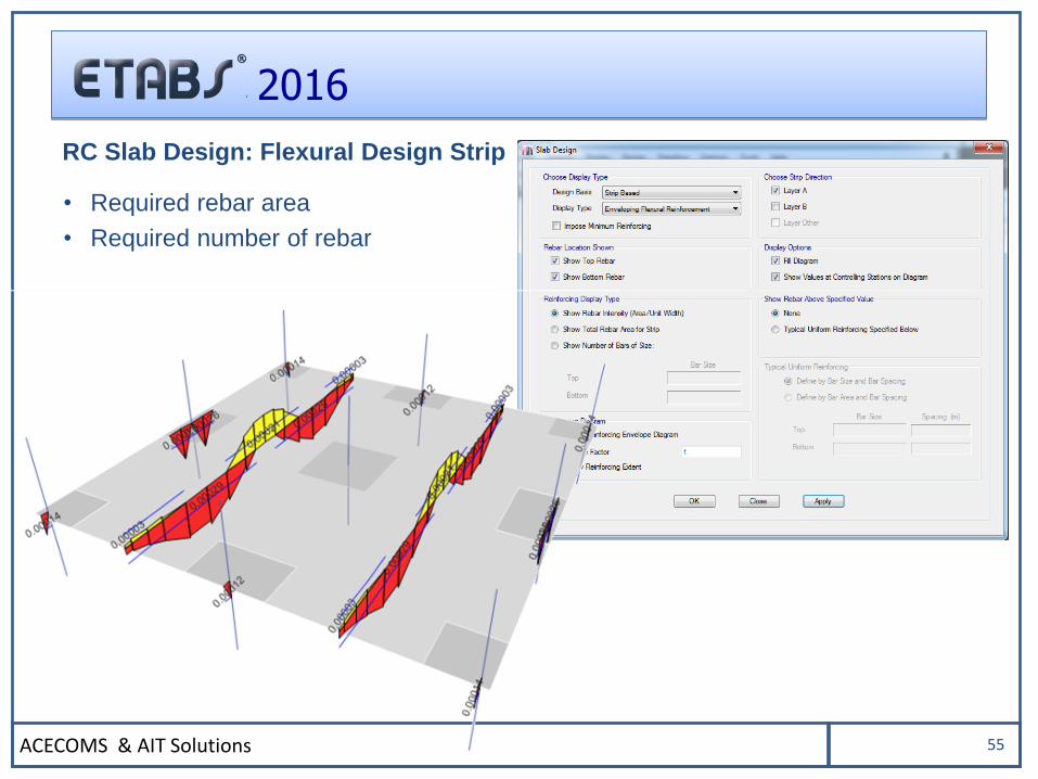
RC Slab Design: Flexural Design Strip
• Required rebar area
• Required number of rebar
ACECOMS & AIT Solutions 56
2016
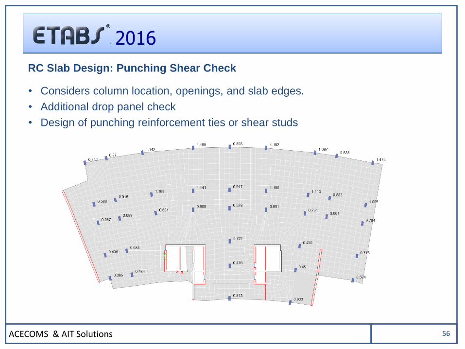
RC Slab Design: Punching Shear Check
• Considers column location, openings, and slab edges.
• Additional drop panel check
• Design of punching reinforcement ties or shear studs
ACECOMS & AIT Solutions 57
2016
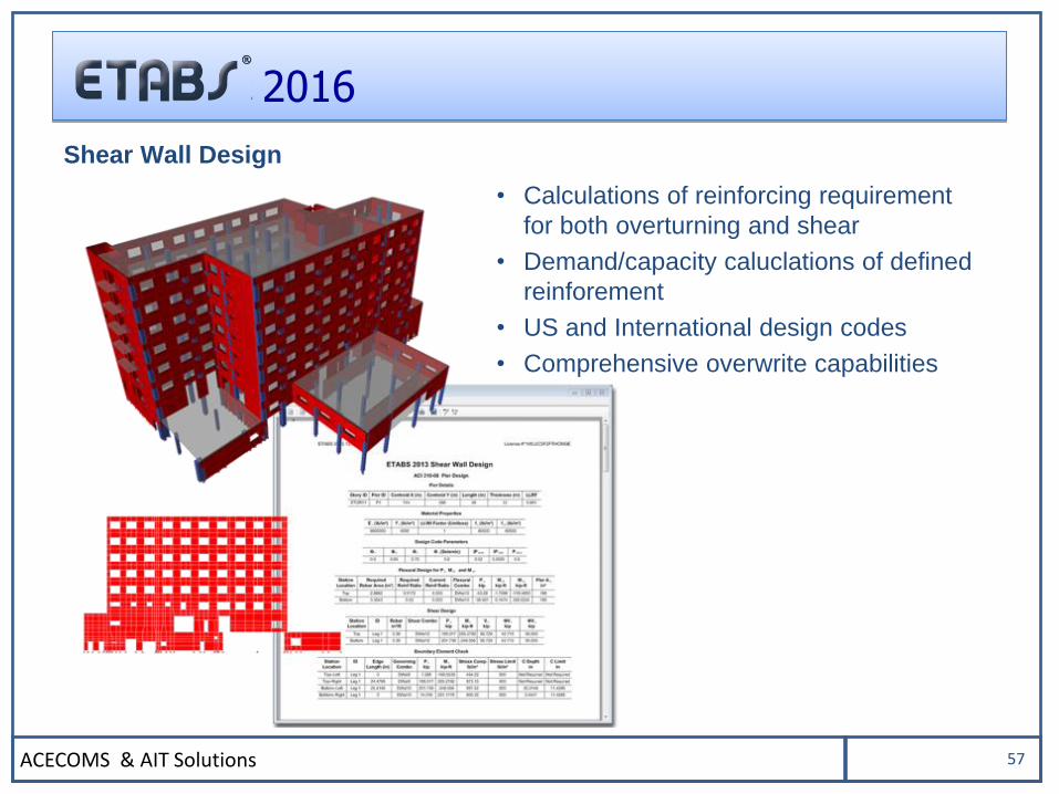
Shear Wall Design
• Calculations of reinforcing requirement
for both overturning and shear
• Demand/capacity caluclations of defined
reinforement
• US and International design codes
• Comprehensive overwrite capabilities
ACECOMS & AIT Solutions 58
2016
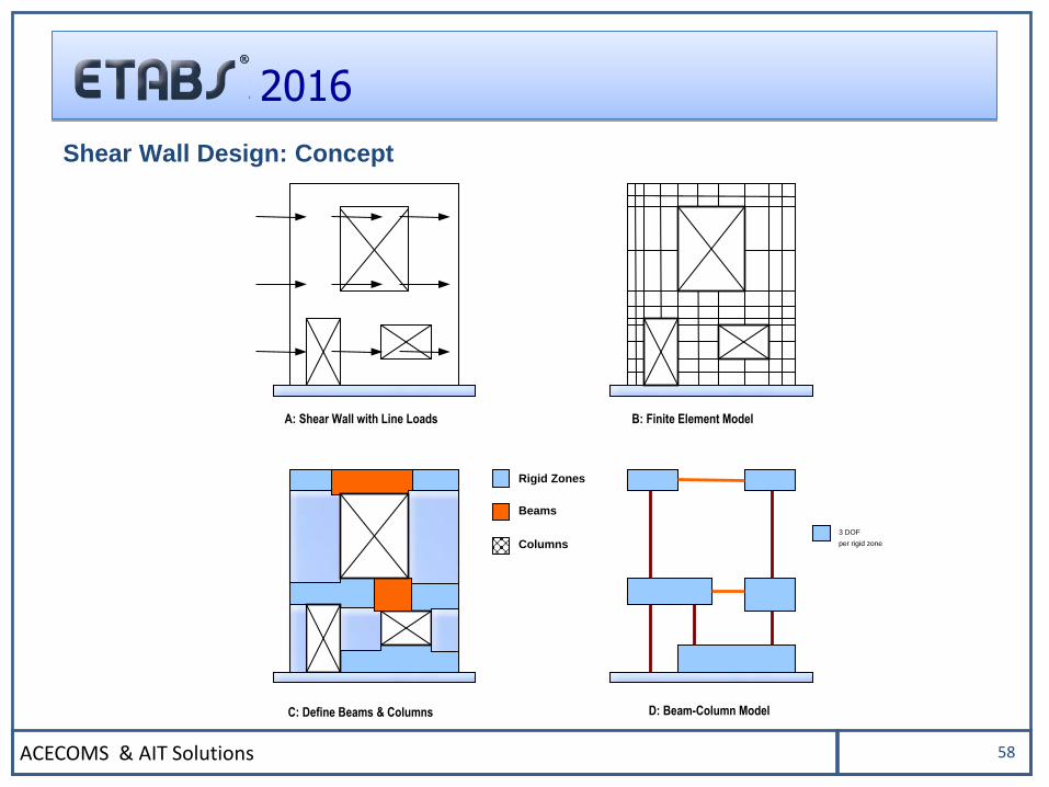
3 DOF
per rigid zone
Rigid Zones
Beams
Columns
A: Shear Wall with Line Loads B: Finite Element Model
C: Define Beams & Columns D: Beam-Column Model
Shear Wall Design: Concept
ACECOMS & AIT Solutions 59
2016
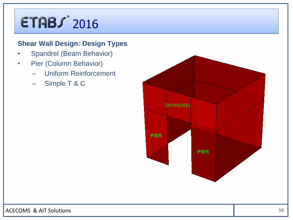
Shear Wall Design: Design Types
• Spandrel (Beam Behavior)
• Pier (Column Behavior)
– Uniform Reinforcement
– Simple T & C
ACECOMS & AIT Solutions 60
2016
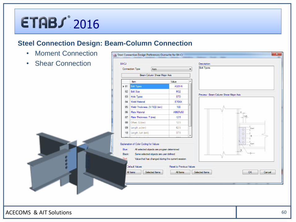
Steel Connection Design: Beam-Column Connection
• Moment Connection
• Shear Connection
ACECOMS & AIT Solutions 61
2016
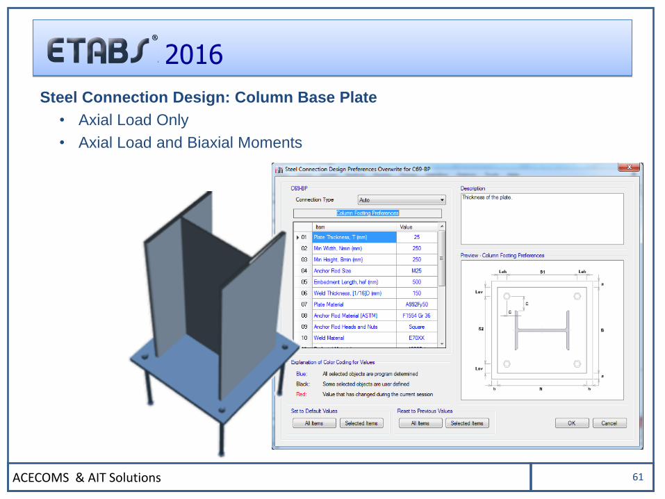
Steel Connection Design: Column Base Plate
• Axial Load Only
• Axial Load and Biaxial Moments
ACECOMS & AIT Solutions 62
2016
OUTPUT and DISPLAY
ACECOMS & AIT Solutions 63
2016
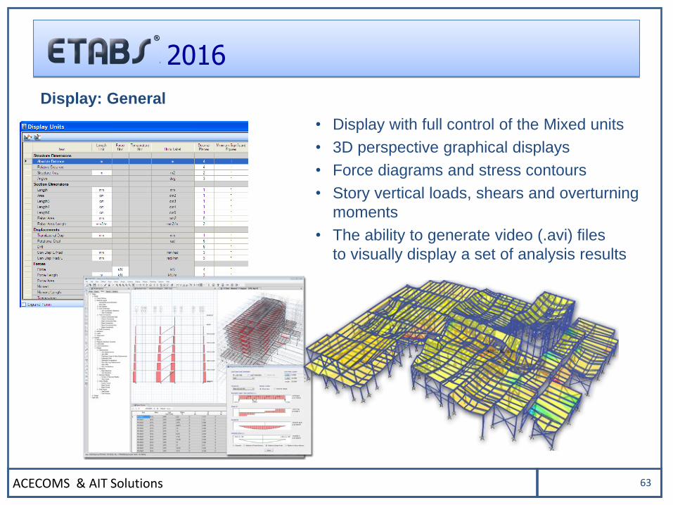
Display: General
• Display with full control of the Mixed units
• 3D perspective graphical displays
• Force diagrams and stress contours
• Story vertical loads, shears and overturning
moments
• The ability to generate video (.avi) files
to visually display a set of analysis results
ACECOMS & AIT Solutions 64
2016
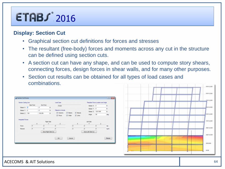
Display: Section Cut
• Graphical section cut definitions for forces and stresses
• The resultant (free-body) forces and moments across any cut in the structure
can be defined using section cuts.
• A section cut can have any shape, and can be used to compute story shears,
connecting forces, design forces in shear walls, and for many other purposes.
• Section cut results can be obtained for all types of load cases and
combinations.
ACECOMS & AIT Solutions 65
2016
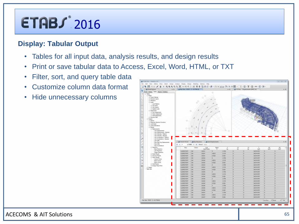
Display: Tabular Output
• Tables for all input data, analysis results, and design results
• Print or save tabular data to Access, Excel, Word, HTML, or TXT
• Filter, sort, and query table data
• Customize column data format
• Hide unnecessary columns
ACECOMS & AIT Solutions 66
2016
DETAILING
ACECOMS & AIT Solutions 67
2016
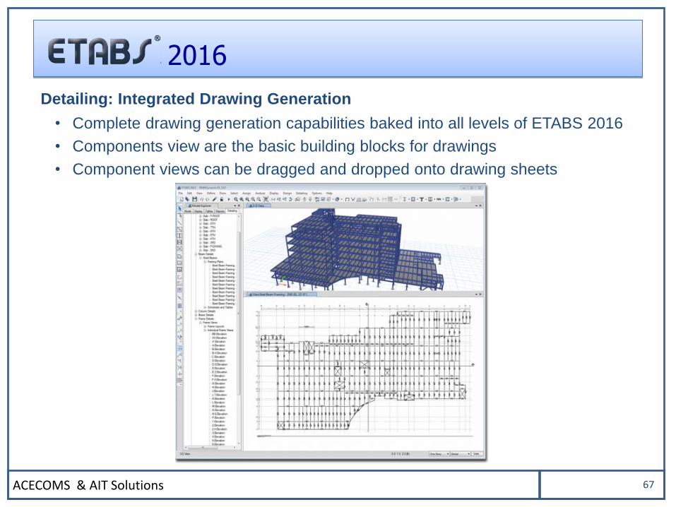
Detailing: Integrated Drawing Generation
• Complete drawing generation capabilities baked into all levels of ETABS 2016
• Components view are the basic building blocks for drawings
• Component views can be dragged and dropped onto drawing sheets
ACECOMS & AIT Solutions 68
2016
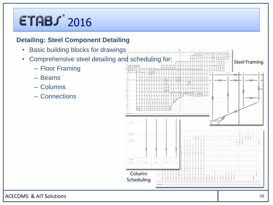
Detailing: Steel Component Detailing
• Basic building blocks for drawings
• Comprehensive steel detailing and scheduling for:
– Floor Framing
– Beams
– Columns
– Connections
ACECOMS & AIT Solutions 69
2016
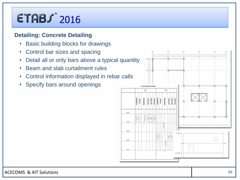
Detailing: Concrete Detailing
• Basic building blocks for drawings
• Control bar sizes and spacing
• Detail all or only bars above a typical quantity
• Beam and slab curtailment rules
• Control information displayed in rebar calls
• Specify bars around openings
ACECOMS & AIT Solutions 70
2016
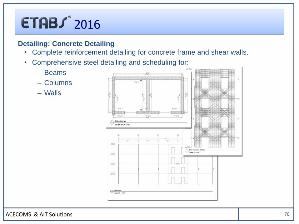
Detailing: Concrete Detailing
• Complete reinforcement detailing for concrete frame and shear walls.
• Comprehensive steel detailing and scheduling for:
– Beams
– Columns
– Walls
ACECOMS & AIT Solutions 71
2016
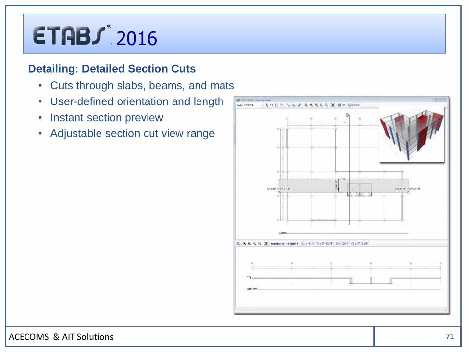
Detailing: Detailed Section Cuts
• Cuts through slabs, beams, and mats
• User-defined orientation and length
• Instant section preview
• Adjustable section cut view range
ACECOMS & AIT Solutions 72
2016
OTHERS
ACECOMS & AIT Solutions 73
2016
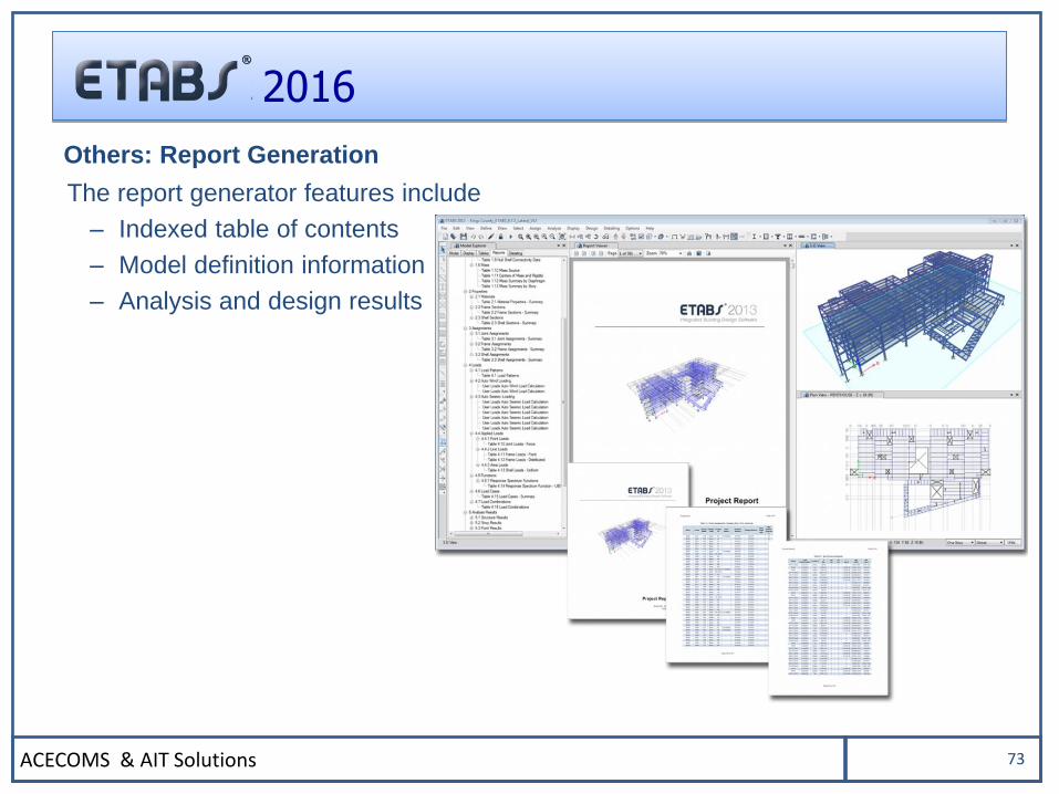
Others: Report Generation
The report generator features include
– Indexed table of contents
– Model definition information
– Analysis and design results
ACECOMS & AIT Solutions 74
2016
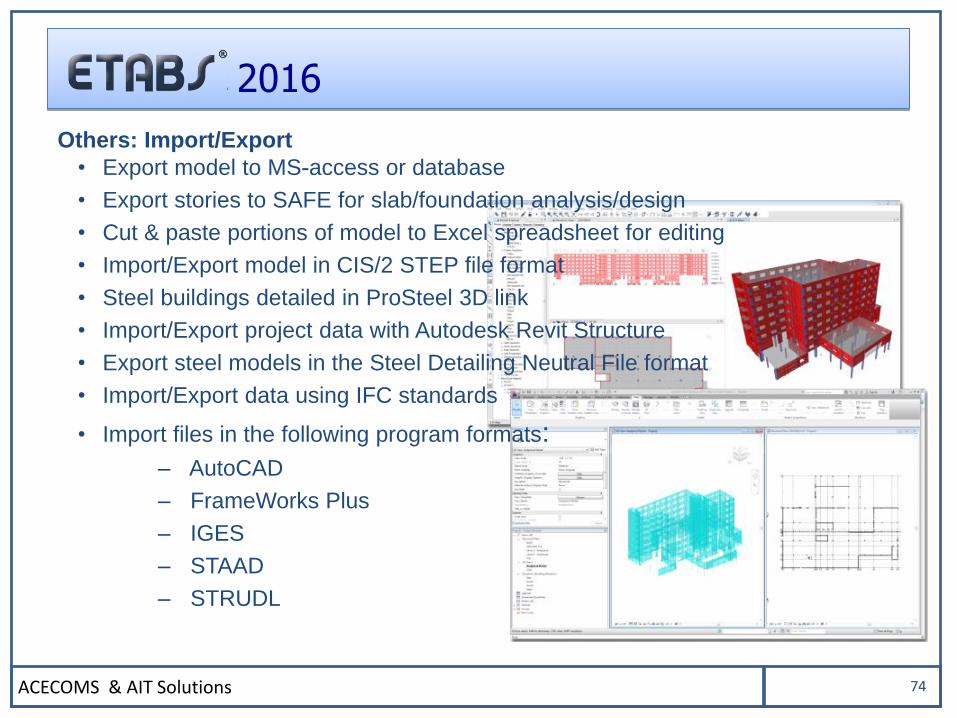
Others: Import/Export
• Export model to MS-access or database
• Export stories to SAFE for slab/foundation analysis/design
• Cut & paste portions of model to Excel spreadsheet for editing
• Import/Export model in CIS/2 STEP file format
• Steel buildings detailed in ProSteel 3D link
• Import/Export project data with Autodesk Revit Structure
• Export steel models in the Steel Detailing Neutral File format
• Import/Export data using IFC standards
• Import files in the following program formats:
– AutoCAD
– FrameWorks Plus
– IGES
– STAAD
– STRUDL
ACECOMS & AIT Solutions 75
2016
THANK YOU