Embed Size (px)
Citation preview
Introduction to 10 Gigabit 64b/66b (Clause 49)
Sowmya S. LuckoorDate: October 22, 2001
Main Topics of Discussion
! Purpose of 64b/66b! Brief outline of 64b/66b structure! 64b/66b PCS Process! Data and Control Characters! Scrambler Principles and
Derivations! Gearbox Principles! State Diagrams of 64b/66b
What is the purpose of 64b/66b?
! Cost Effective
! Supports New Applications and Data
! Alternate to 8b/10b structure
! Complexity of hardware reduced! 10 => 10.3 vs. 10 => 12.5
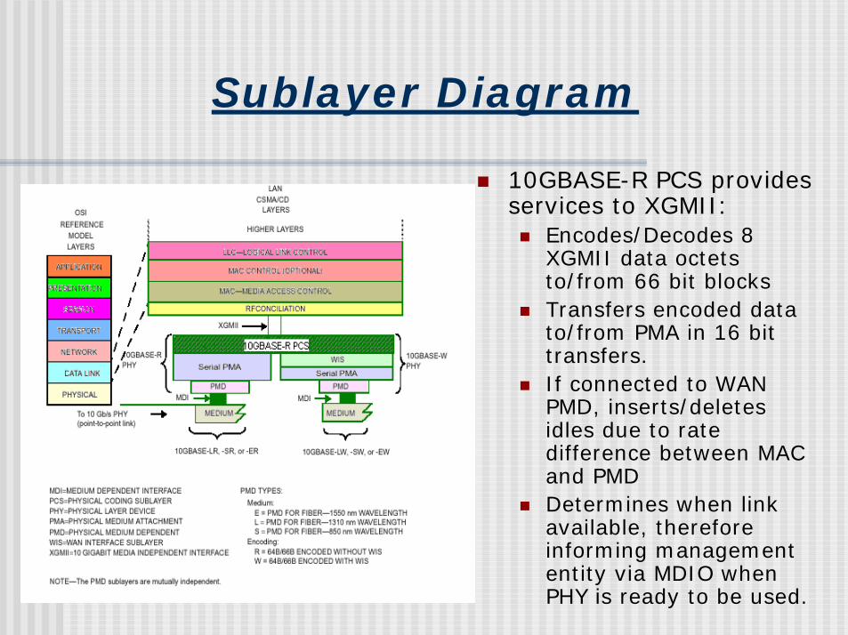
Sublayer Diagram
! 10GBASE-R PCS provides services to XGMII:! Encodes/Decodes 8
XGMII data octets to/from 66 bit blocks
! Transfers encoded data to/from PMA in 16 bit transfers.
! If connected to WAN PMD, inserts/deletes idles due to rate difference between MAC and PMD
! Determines when link available, therefore informing management entity via MDIO when PHY is ready to be used.
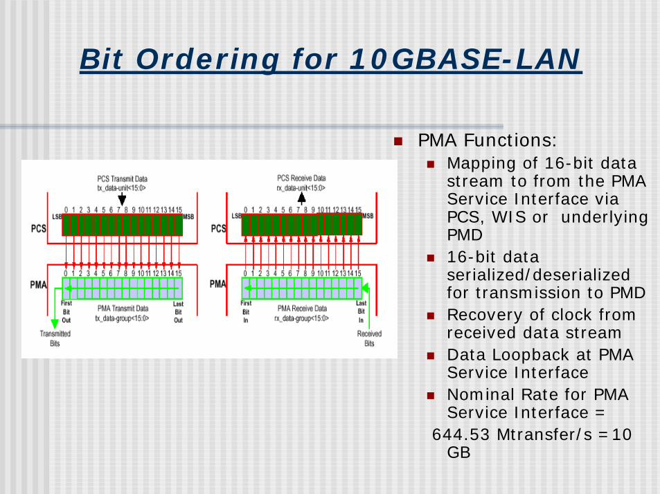
Bit Ordering for 10GBASE-LAN
! PMA Functions:! Mapping of 16-bit data
stream to from the PMA Service Interface via PCS, WIS or underlying PMD
! 16-bit data serialized/deserialized for transmission to PMD
! Recovery of clock from received data stream
! Data Loopback at PMA Service Interface
! Nominal Rate for PMA Service Interface =
644.53 Mtransfer/s =10 GB
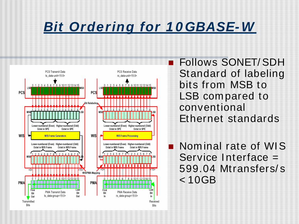
Bit Ordering for 10GBASE-W
! Follows SONET/SDH Standard of labeling bits from MSB to LSB compared to conventional Ethernet standards
! Nominal rate of WIS Service Interface = 599.04 Mtransfers/s <10GB
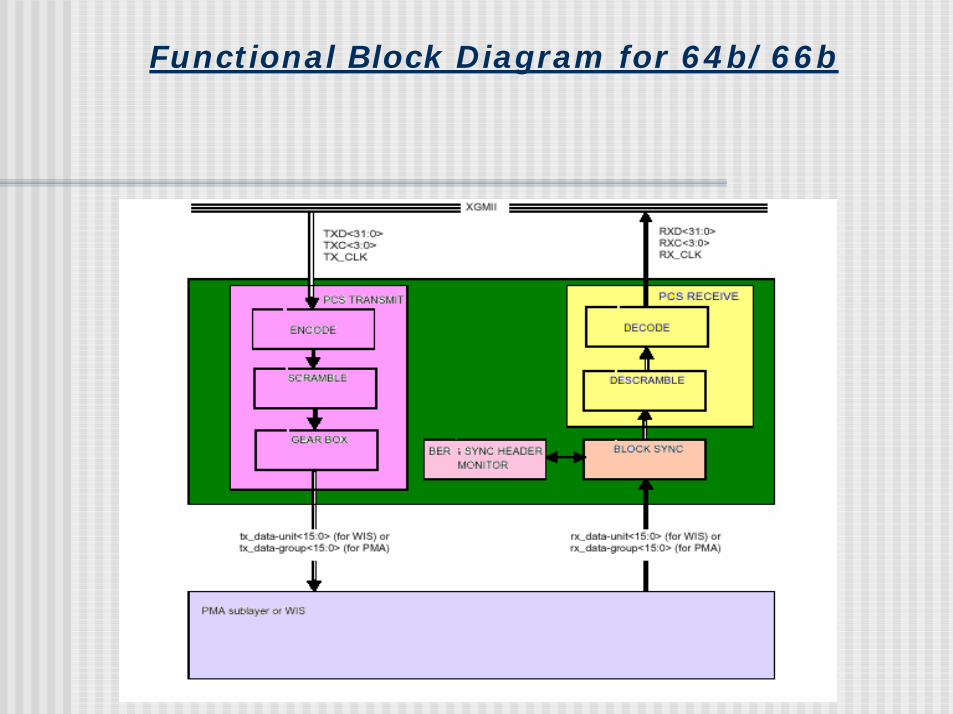
Functional Block Diagram for 64b/66b
Functions within the PCS
! PCS Transmit (Normal Mode and Jitter Test Mode)
! Block (Frame) Synchronization! PCS Receive! BER Monitor Processes (assuming
10GBASE-(LR, SR, ER) or 10GBASE-(LW, SW, EW)
! Maps packets between XGMII format and PMA service interface format
PCS Transmit Process
! Transmit channel in normal mode:! Blocks generated continuously based upon
TXD<31:0> and TXC<3:0> signals on XGMII! 66 bit blocks are packed by gearbox into 16 bit data
units and sent to PMA or WIS via PMA_UNITDATA.REQUEST or WIS_UNITDATA.REQUEST, respectively.
! If WIS present, adapts rates between XGMII and WIS by deleting IDLE characters when necessary.
! Transmit channel in jitter test mode:! Jitter test pattern packed into transmit data units,
which are sent to PMA Service Interface.
PCS Receive Process
! Continuously accepts blocks once synchronization is complete
! Monitors blocks to generate RXD<31:0> and RXC<3:0> on XGMII
! When WIS is present, PCS receive process adapts between WIS and XGMII data rates by inserting IDLE characters
PCS Synchronization Process
! Continuously monitors PMA or WIS SIGNAL_DETECT. When SIGNAL_DETECT indicates OK, PCS SYNC process accepts data units and attempts to attain sync.
! Frame synchronization based on 2-bit sync header
! SYNC_STATUS flag set to indicate that PCS has received synchronization.
Bit Error Rate(BER) Monitor Process
! When synchronization is complete, signal quality monitoring is done by the BER Monitor Process.
! Asserting hi_ber occurs if errors are detected, therefore stopping acceptance of incoming blocks.
! When sync_status is asserted and hi_ber is deasserted, the PCS Received Process can accept frames.
64b/66b Transmission Code
! Improves transmission characteristics of information transferred across link to support control and data characters.
! Transmission encoding ensures clock recovery is possible at receiver as well as detection of invalid codes when transmitting/receiving.
! Bit errors that form valid blocks that are not detected by transmission encoding, are detected by the frame’s CRC.
! Block alignment is achieved by the synchronization headers.
Notation Conventions
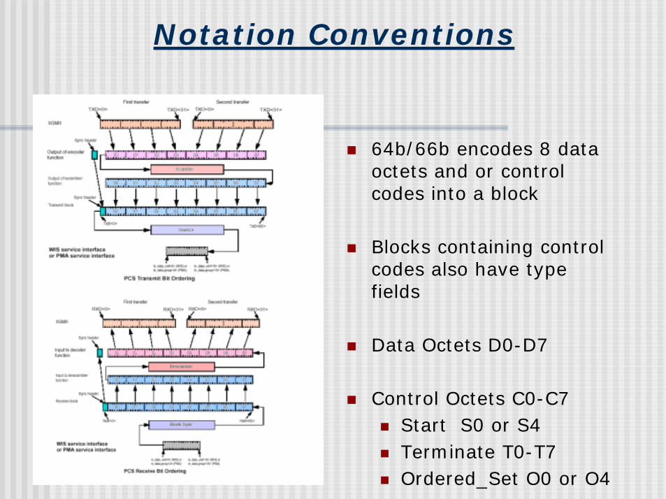
! 64b/66b encodes 8 data octets and or control codes into a block
! Blocks containing control codes also have type fields
! Data Octets D0-D7
! Control Octets C0-C7! Start S0 or S4! Terminate T0-T7! Ordered_Set O0 or O4
Code Process
Control Characters
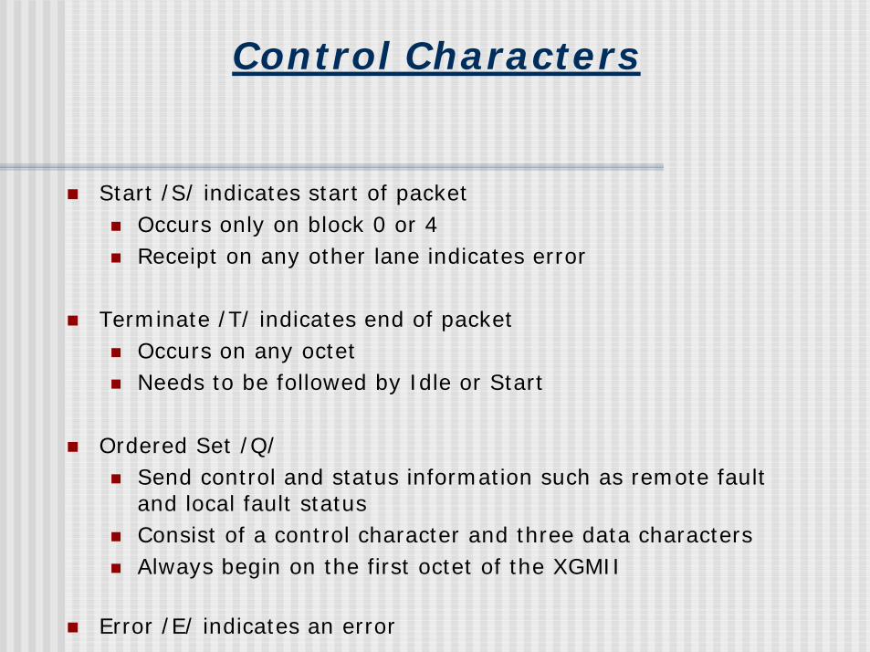
! Start /S/ indicates start of packet! Occurs only on block 0 or 4 ! Receipt on any other lane indicates error
! Terminate /T/ indicates end of packet! Occurs on any octet! Needs to be followed by Idle or Start
! Ordered Set /Q/ ! Send control and status information such as remote fault
and local fault status! Consist of a control character and three data characters! Always begin on the first octet of the XGMII
! Error /E/ indicates an error
Code Groups
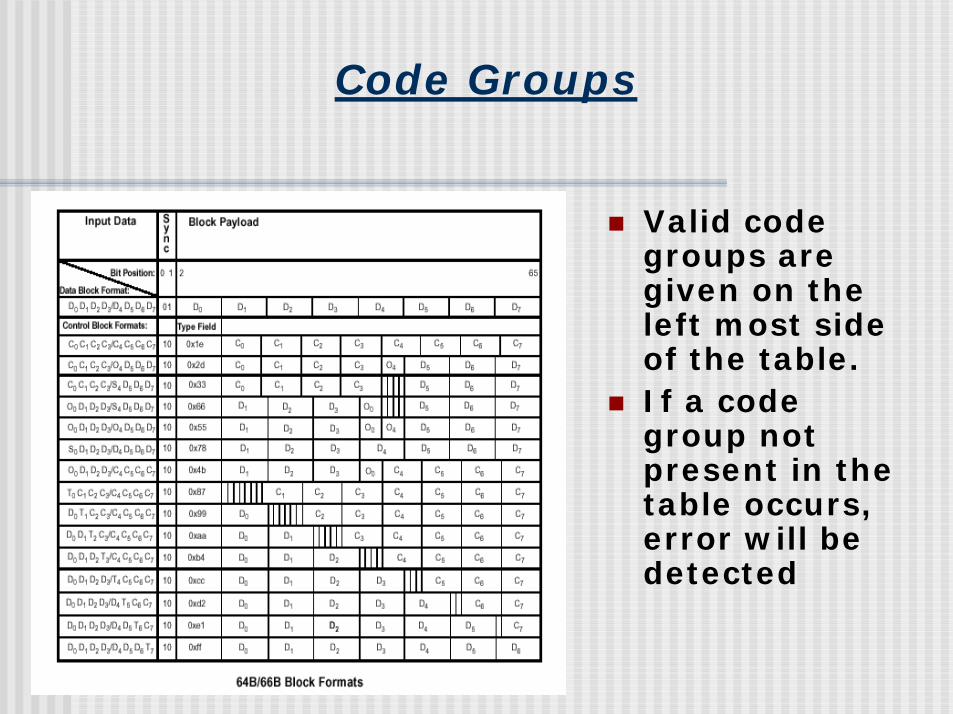
! Valid code groups are given on the left most side of the table.
! If a code group not present in the table occurs, error will be detected
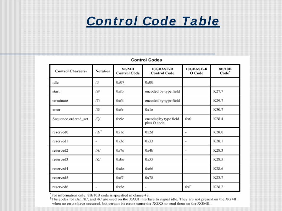
Control Code Table
Examples of Code for 64b/66b transmit
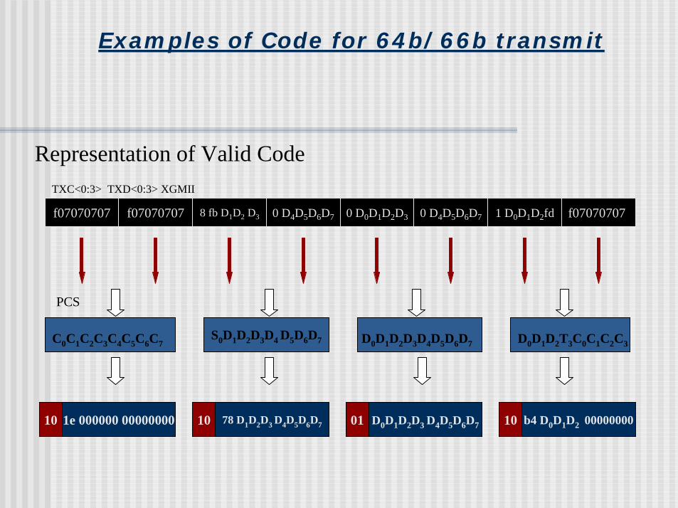
f07070707 f07070707 8 fb D1D2 D3 0 D4D5D6D7 0 D0D1D2D3 0 D4D5D6D7 1 D0D1D2fd f07070707
C0C1C2C3C4C5C6C7S0D1D2D3D4 D5D6D7 D0D1D2D3D4D5D6D7 D0D1D2T3C0C1C2C3
TXC<0:3> TXD<0:3> XGMII
10 1e 000000 00000000 10 78 D1D2D3 D4D5D6D7 01 D0D1D2D3 D4D5D6D7 10 b4 D0D1D2 00000000
Representation of Valid Code
PCS
Examples of Code for 64b/66b transmit (2)
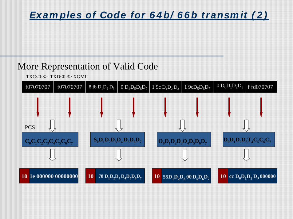
f07070707 f07070707 8 fb D1D2 D3 0 D4D5D6D7 1 9c D1D2 D3 1 9cD5D6D7 f fd070707
C0C1C2C3C4C5C6C7S0D1D2D3D4 D5D6D7 O0D1D2D3O4D5D6D7
TXC<0:3> TXD<0:3> XGMII
10 1e 000000 00000000 10 78 D1D2D3 D4D5D6D7 10 55D1D2D3 00 D5D6D7 10 cc D0D1D2 D3 000000
More Representation of Valid Code
D0D1D2D3T4C5C6C7
PCS
0 D0D1D2D3
Examples of Code for 64b/66b transmit (3)
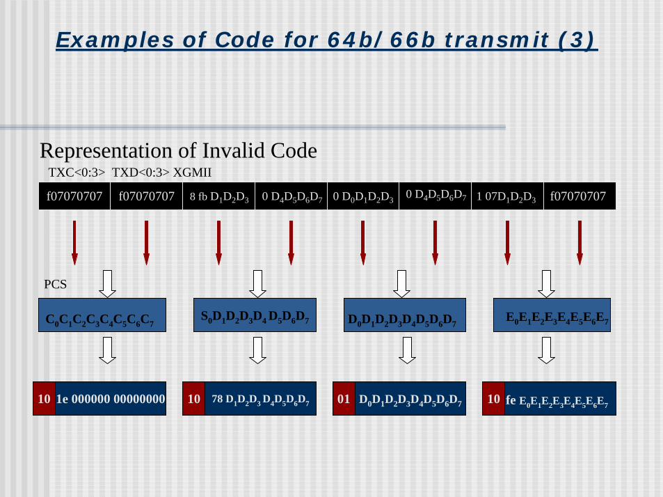
Representation of Invalid Code
f07070707 f07070707 8 fb D1D2D3 0 D4D5D6D7 0 D0D1D2D3 1 07D1D2D3 f07070707
C0C1C2C3C4C5C6C7S0D1D2D3D4 D5D6D7 D0D1D2D3D4D5D6D7
TXC<0:3> TXD<0:3> XGMII
10 1e 000000 00000000 10 78 D1D2D3 D4D5D6D7 01 D0D1D2D3D4D5D6D7 10
E0E1E2E3E4E5E6E7
fe E0E1E2E3E4E5E6E7
PCS
0 D4D5D6D7
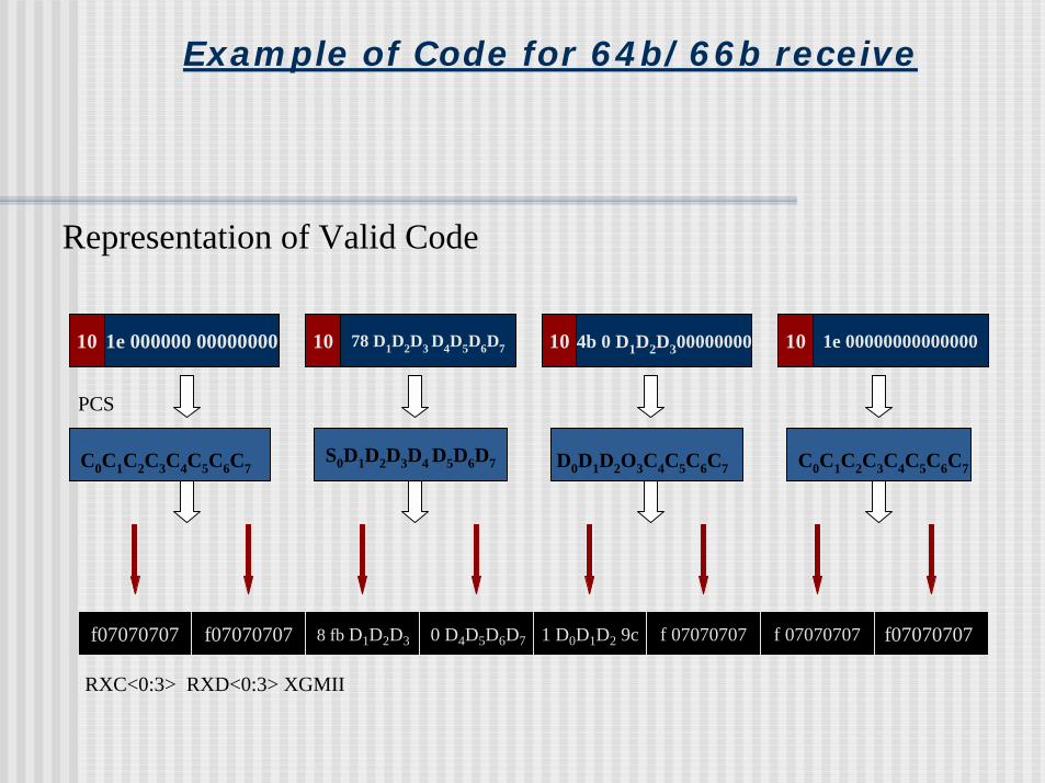
Example of Code for 64b/66b receive
10 1e 000000 00000000 10 78 D1D2D3 D4D5D6D7 10 4b 0 D1D2D300000000 10 1e 00000000000000
C0C1C2C3C4C5C6C7S0D1D2D3D4 D5D6D7 D0D1D2O3C4C5C6C7 C0C1C2C3C4C5C6C7
f07070707 f07070707 8 fb D1D2D3 0 D4D5D6D7 1 D0D1D2 9c f 07070707 f 07070707 f07070707
RXC<0:3> RXD<0:3> XGMII
Representation of Valid Code
PCS
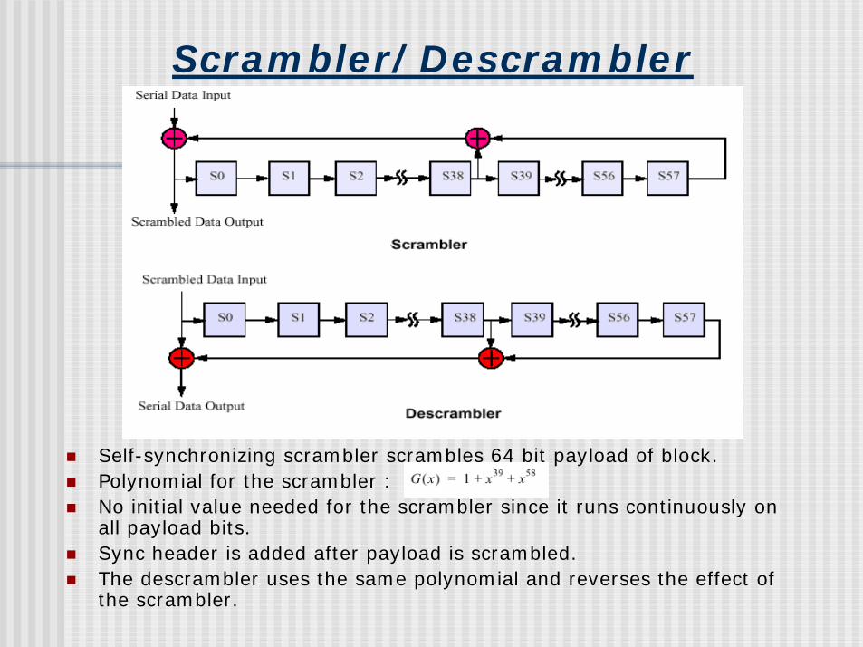
Scrambler/Descrambler
! Self-synchronizing scrambler scrambles 64 bit payload of block.! Polynomial for the scrambler : ! No initial value needed for the scrambler since it runs continuously on
all payload bits.! Sync header is added after payload is scrambled. ! The descrambler uses the same polynomial and reverses the effect of
the scrambler.
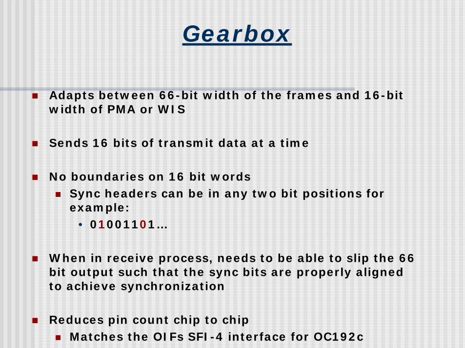
Gearbox
! Adapts between 66-bit width of the frames and 16-bit width of PMA or WIS
! Sends 16 bits of transmit data at a time
! No boundaries on 16 bit words! Sync headers can be in any two bit positions for
example:• 01001101…
! When in receive process, needs to be able to slip the 66 bit output such that the sync bits are properly aligned to achieve synchronization
! Reduces pin count chip to chip! Matches the OIFs SFI-4 interface for OC192c
64b/66b State Diagrams
! Four state machines:! Lock State Machine
! BER Monitor State Machine
! Transmit State Machine
! Receive State Machine
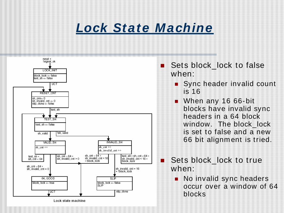
Lock State Machine
! Sets block_lock to false when:! Sync header invalid count
is 16! When any 16 66-bit
blocks have invalid sync headers in a 64 block window. The block_lock is set to false and a new 66 bit alignment is tried.
! Sets block_lock to true when:! No invalid sync headers
occur over a window of 64 blocks
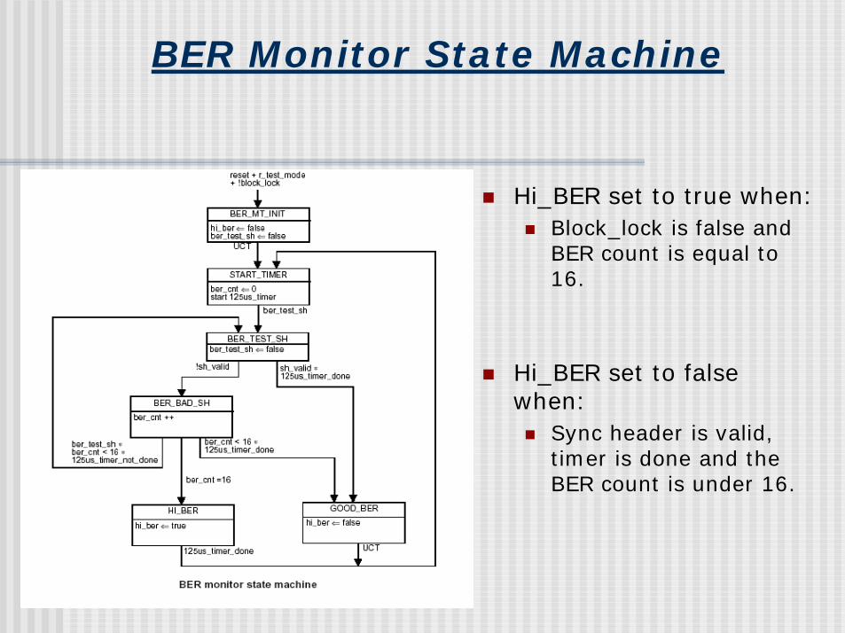
BER Monitor State Machine
! Hi_BER set to true when:! Block_lock is false and
BER count is equal to 16.
! Hi_BER set to false when:! Sync header is valid,
timer is done and the BER count is under 16.
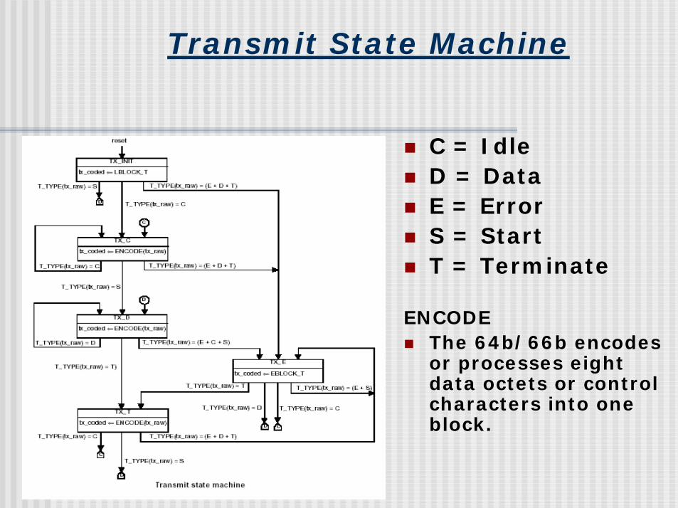
Transmit State Machine
! C = Idle! D = Data! E = Error! S = Start! T = Terminate
ENCODE! The 64b/66b encodes
or processes eight data octets or control characters into one block.
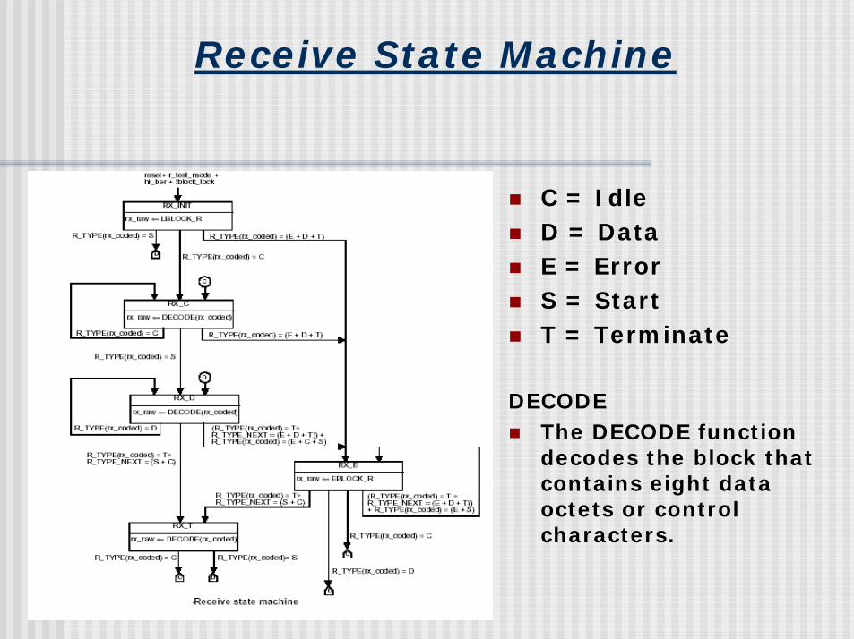
Receive State Machine
! C = Idle! D = Data! E = Error! S = Start! T = Terminate
DECODE! The DECODE function
decodes the block that contains eight data octets or control characters.
Credit
! Diagrams from IEEE P802.3ae/D3.2


![Demonstration of a 16 Lane 10G Aurora 64B/66B Link on ......(UG476) [Ref 1] can be used to replicate the example design demo created in this application note. In this application note,](https://img.pdfslide.us/doc/110x75/60dbb610aff2f95a9c7b0f07/demonstration-of-a-16-lane-10g-aurora-64b66b-link-on-ug476-ref-1-can.jpg)