Embed Size (px)
Citation preview

1SONANCE and the SONANCE Logo are trademarks of Dana Innovations. ©2017 Dana Innovations. All rights reserved.
SONANCE.COM
TABLE OF CONTENTS
INTRODUCTION: INVISIBLE SPEAKER IS4 C 2-3
SPECIFICATIONS 2-3
IS4 C SPEAKER INSTALLATION DETAIL VIEW 4
WIRE GAUGE CHART 4
NEW CONSTRUCTION 5-8
EXISTING CONSTRUCTION 9-11
FINISHING INSTRUCTIONS 12-16
NOTES 17
WARRANTY 18
I N S T A L L A T I O N M A N U A L
I N V I S I B L E S P E A K E R I S 4 C

2
INTRODUCTIONSONANCE offers the ability to contribute to brilliant architecture and genius design by removing all speaker grilles from the room décor. SONANCE INVISIBLE SERIES offers audiophile quality and ease of installation to any design project.
SONANCE INVISIBLE SERIES
IS4 C
The IS4 C is for any commercial or residential settings where a 70 or 100 volt system is being used. The IS4 C features all the industry standard tap settings as well as an 8-ohm bypass.
SPECIFICATIONS
Tweeter 4 sq. in (27 sq. cm) planar diaphragm, driven by a 1” (25mm) voice coil
Midrange 17 sq. in (110 sq. cm) planar diaphragm, driven by a 1” (25mm) voice coil
Woofer 113 sq. in (732 sq. cm) planar diaphragm, driven by a 2” (50mm) voice coil
Frequency Response 40Hz – 20kHz ±3dB
Transformer Primary voltage: 70V, 100V Primary taps (70V): 0.5W, 1.5W, 3W, 6W, 12W, 24W, 48W Primary taps (100V): 1.5W, 3W, 6W, 12W,24W, 48W 5-ohm bypass
Power Handling 100 watts RMS
Sensitivity 90dB (1W/1 meter)
Dispersion 170º hemispherical up to 10 kHz
Finish Paper surface ready for up to 1/8” (3mm) flexible material* and paint
Overload Protection: Three independent self-resetting gel switches (low, mid and high)
Cutout Dims - Without Enclosure (WxHxD) 16-1/8” x 24-5/32” x 2” (409.5mm x 613.5mm x 51mm)
Cutout Dims - With Enclosure (WxHxD) 16-1/8” x 24-5/32” x 3-11/16” (409.5mm x 613.5mm x 94mm)
Back Box (WxHxD) 14-1/8” x 22-3/16” x 2-1/8” (358mm x 563.5mm x 54mm)
Shipping Weight: 28 lbs (12.7 kg) each
Environment Temperature: 0° - 125°F (-17.7 - 51.7°C)
*Pliable, elastic material such as joint compound or wallpaper. Specifications subject to change.
UL2043

WARNING: Do not mount and finish over the speaker until you have selected the necessary tap setting to achieve the desired volume level. After selecting a given tap, play the speaker with an actual audio signal to verify the speaker provides adequate volume. If necessary, re-select a lower or higher tap setting. POWER
SELECT(WATTS)
70V
100V
IS4 C.5
W 1
.5W
3W 6W 12W 24W 48W
5Ω
1.5W 3W
6W
12W 24W 48W
5Ω
3
Using a #2 Phillips head screwdriver remove the two screws securing the terminal cover plate.
1.
2.
3.
When using speaker wire without conduit, run the wire through the hole on the terminal cover plate. Wire needs to be clamped as required by national or local codes. Connect the wires to the terminal block being certain to connect the positive wire to terminal marked + and the negative wire to the terminal marked – .
When using conduit attach the conduit connector to the terminal cover plate then connect the wires to the terminal block being certain to connect the positive wire to terminal marked + and the negative wire to the terminal marked – .
Using a flat head screwdriver set the transformer tap to the correct tap setting for your installation. We strongly recommend testing the system with music to determine the correct output level.
IS4 C Wiring Diagram
Amplifier
IS4 C Speakers

4
UNDERSTANDING THE INVISIBLE SERIES INSTALLATION
INVISIBLE SERIES SPEAKER INSTALLATION DETAIL VIEW
WIRE GAUGE CHART
Refer to the following table when selecting the proper wire gauge for your system:
16” (40.6cm) standard framing
Drywall
Stud
Fiberglass Mesh Tape
Joint Compound
Drywall Screw (wall board)
Drywall Screw (speaker)
Height Shim
Speaker Frame
SONANCE INVISIBLE SERIES SPEAKER
1/8” (3mm) maximum topping compound buildup over active speaker area
Note: IMPORTANT CONSIDERATION FOR LOCATING THE IS4 C ON WALLS
For wall installations, locate the bottom of the Invisible Series Speaker at least 7 ft. (2.1m) up from the floor. Placing the speaker lower on the wall will put it at risk for having picture nails or other hanging devices driven through the diaphragm and damaging the speaker. Since the final surface finish enables the speaker to completely disappear, it is critical to locate the speaker high enough on the wall to protect it for the future. Resulting damage of this type is not covered by the warranty.
ENCLOSURE
W I R E G A U G E C H A R TWIRE GAUGE
16
18
20
22
24
5 WATT
10,000 FT
9,000 FT
5,500 FT
3,400 FT
2,100 FT
10 WATT
7,000 FT
4,500 FT
2,700 FT
1,700 FT
1,000 FT
15 WATT
4,600 FT
2,800 FT
1,800 FT
1,100 FT
700 FT
30 WATT
2,300 FT
1,400 FT
900 FT
550 FT
350 FT
50 WATT
1,400 FT
830 FT
540 FT
330 FT
210 FT
100 WATT
700 FT
415 FT
270 FT
115 FT
105 FT
200 WATT
350 FT
205 FT
135 FT
60 FT
50 FT
FOR TECHNICAL SUPPORT CALL (949) 492-7777OR VISIT WWW.SONANCE.COM/IN-WALL-IN-CEILING/INVISIBLE-SERIES

5
1 . Wire stud bay prior to mounting drywall. See page 4 for wire gauge chart.
3 . With the aid of a level, screw the space saver to the studs. Ensure the speaker cable will have easy access once the space saver is removed.
4 . Secure edges of the space saver.2 . Place space saver in desired final location of speaker.
NEW CONSTRUCTION
IS4 C Space Saver Part Number: 92723

6
NEW CONSTRUCTION
5. After all drywall is hung, begin speaker installation by removing space saver.
6. Be careful not to damage the exposed drywall during space saver removal.

TALL SIDE 5/8” (16MM)DRYWALL SHORT SIDE
1/2” (12MM)DRYWALL
THIN SHIM 5/16” (8MM)INTERNATIONALAPPLICATIONS
7
NEW CONSTRUCTION
7. Pull 2-conductor speaker wire down into the exposed opening.
8. Select the appropriate shim for the application.* Use cardboard shims for fine tuning.
*All installations in 1/2" (13mm) and 5/8" (16mm) drywall with wood stud construction require a shim.
9. Peel off corresponding adhesive backing.
10. Press shim firmly into position, aligning screw holes.

8
11. Connect speaker wire to the appropriate terminal on the speaker. (Speaker shown with optional enclosure.)
12. Insert speaker into opening.
13. Secure speaker with at least 4 drywall screws on each side. Top and bottom are optional. Do not over tighten.
14. Go to Finishing Instructions starting on page 12.
NEW CONSTRUCTION
TEST THE SPEAKER FOR 60 SECONDS WITH AN AUDIO SOURCE BEFORE COVERING WITH DRYWALL COMPOUND! This is the last point any wiring corrections can be made. After test is complete finish securing with remaining drywall screws.
IS4 C Space Saver Part Number: 92723

FIGURE 6: EXPOSED STUDS AFTER DRYWALL IS REMOVED
FIGURE 4: MARKING THE SPEAKER LOCATION
FIGURE 5: CUTTING THE MOUNTING HOLE
Half (¾”) ofEach Stud / Joist
Should BeExposed
3. Use Utility Knife to Complete Horizontal Cuts
9
EXISITNG CONSTRUCTION1. Determine the location for the speaker.2. Using a stud finder, locate the first studs/joists to
the right and left of the speaker position.3. Mark the centers of the studs/joists. (See Figure 4, below.)
4. Using the speaker as a template, determine the desired speaker location on the wall. Mark the speaker’s top and bottom edges on the drywall. (See Figure 4, above.)
5. Before proceeding, perform an obstruction survey to be certain that there are no studs, conduit, pipes, heating ducts, pocket doors, or air returns in the wall cavity that will interfere with the speaker.
6. Using a drywall saw, cut the drywall along the top and bottom horizontal marks UP TO THE INSIDE EDGES OF THE LEFT AND RIGHT STUDS/JOISTS. (See Figure 5 below.)
7. Using a utility knife, cut the drywall along the vertical marks at the centers of the studs/ joists. Use the utility knife to complete the horizontal cuts at each stud/joist. (See Figure 5, below.) Remove the drywall from the opening.
• This should expose only ¾” (19mm) of each stud/joist or half of the stud/joist surface. (See Figure 6.)
8. Test-fit the speaker into the opening, verifying that all of the speaker’s edges are even with the drywall edges. If necessary, trim the edges of the drywall to properly accommodate the speaker.
1. Mark Stud Centerlines on Wall
2. Hold Speaker Against Wall at Mounting Location
3. Mark Top and Bottom Edges on Wall
1. Use Drywall Saw to Cut Along Top and Bottom Lines Up to Inside Edges of Studs
2. Use Utility Knife to Cut Along Stud Centerlines

TALL SIDE 5/8” (16MM)DRYWALL SHORT SIDE
1/2” (12MM)DRYWALL
THIN SHIM 5/16” (8MM)INTERNATIONALAPPLICATIONS
*All installations in 1/2" (13mm) and 5/8" (16mm) drywall with wood stud construction require a shim.
10
EXISITNG CONSTRUCTION
9. Pull 2-conductor speaker wire down into the exposed opening.
10. Select the appropriate shim for the application.* Use cardboard shims for fine tuning.
11. Peel off corresponding adhesive backing.
12. Press shim firmly into position, aligning screw holes.

11
13. Connect speaker wire to the appropriate terminal on the speaker.
14. Insert speaker into opening.
15. Secure speaker with at least 4 drywall screws on each side. Top and bottom is optional. Do not over tighten.
EXISITNG CONSTRUCTION
TEST THE SPEAKER FOR 60 SECONDS WITH AN AUDIO SOURCE BEFORE COVERING WITH DRYWALL COMPOUND! This is the last point any wiring corrections can be made. After test is complete finish securing with remaining drywall screws.
IS4 C Space Saver Part Number: 92723

12
FINISHING INSTRUCTIONS
1 . Fill the gap between speaker and drywall with 5 minute setting type joint compound (hot mud).
2 . Feather all edges.
3 . Allow hot mud to set slightly before applying mesh tape.
13
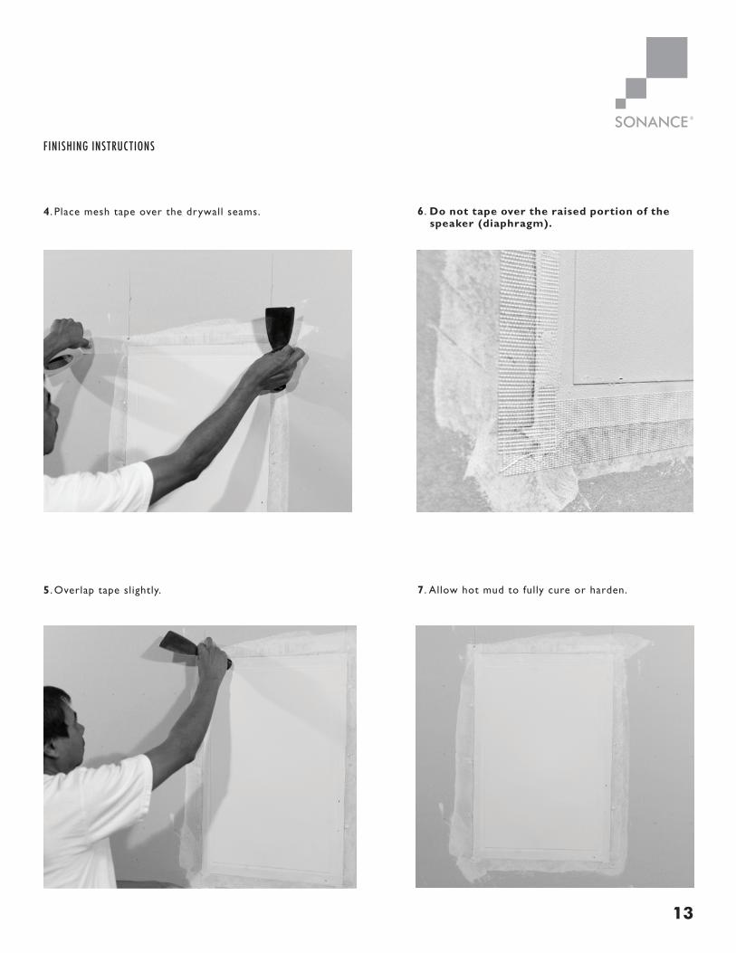
4 . Place mesh tape over the drywall seams.
5 . Overlap tape slightly. 7 . Allow hot mud to fully cure or harden.
6 . Do not tape over the raised portion of the speaker (diaphragm).
FINISHING INSTRUCTIONS

14
8 . Once hot mud has fully cured or hardened, begin to Build layers of topping compound over speaker.
9 . Build layers of compound as needed to obtain a flat surface.
10. Feather in all surfaces.
11. Allow first coat to fully cure or harden.
FINISHING INSTRUCTIONS

15
12. Start a second coat covering the entire surface of the speaker and all adjoining surfaces.
13 . Compound buildup on the active surface of the speaker should not exceed 1/8” (3mm).
14. Detail the compound to minimize tool marks.
15. Build more coats as necessary to achieve desired finish.
FINISHING INSTRUCTIONS

16
BEST PRACTICE
A 60 MICRON SANDING FILM IS RECOMMENDED FOR FINAL SANDING.
16 . Each successive coat should be thinner than the last. The final coat should be a very light application (skim coat).
17 . After final coat is applied and has dried, use a manual pole sander or block sander on entire wall (do not use a power sander). Wall surface should show no signs of a speaker. If any defect is found, skim coat entire area, and sand down again.
TOTAL MATERIAL OVER ACTIVE SURFACE OF THE SPEAKER CAN NOT EXCEED 1/8TH OF AN INCH (3mm).
IMPORTANT
FINISHING INSTRUCTIONS

17
NOTES:

18
©2017. All rights reserved. SONANCE and SONANCE INVISIBLE SERIES are registered trademarks of Dana Innovations.Due to continuous product improvement, all features and specifications are subject to change without notice.
For the latest SONANCE product specification information visit our website: www.sonance.com 991 Calle Amanecer | San Clemente, CA 92673 USA
T. (949) 492-7777 | F. (949) 361-5151 33-5838
Rev 5.11.17
LIMITED FIFTEEN (15) YEAR WARRANTY
Sonance warrants to the first end-user purchaser that this Sonance-brand product (“Product”), when purchased from an authorizedSonance Dealer/Distributor and installed by a Sonance installer, will be free from defective workmanship and materials in theinitial installation for the period stated below. Subject to the additional limitations stated below, Sonance will (a) at its option andexpense during the warranty period, either repair the defect or replace the Product with a new or remanufactured Product or areasonable equivalent, and (b) arrange at its reasonable expense to re-install the Product and prepare the surface of the speakerand/or mounting platform for finishing and nothing more.
EXCLUSIONS
TO THE EXTENT PERMITTED BY LAW, THE WARRANTY SET FORTH ABOVE IS IN LIEU OF, AND EXCLUSIVE OF, ALL OTHER WARRANTIES,EXPRESS OR IMPLIED, AND IS THE SOLE AND EXCLUSIVE WARRANTY PROVIDED BY SONANCE. ALL OTHER EXPRESS AND IMPLIEDWARRANTIES, INCLUDING THE IMPLIED WARRANTY OF MERCHANTABILITY, IMPLIED WARRANTY OF FITNESS FOR USE, AND IMPLIEDWARRANTY OF FITNESS FOR A PARTICULAR PURPOSE ARE SPECIFICALLY EXCLUDED. No one is authorized to make or modify anywarranties on behalf of Sonance.
The warranty stated above is the sole and exclusive remedy and Sonance’s performance shall constitute full and final satisfaction ofall obligations, liabilities and claims with respect to the Product. IN ANY EVENT, SONANCE SHALL NOT BE LIABLE FOR CONSEQUENTIAL,INCIDENTAL, ECONOMIC, PROPERTY, BODILY INJURY, OR PERSONAL INJURY DAMAGES ARISING FROM THE PRODUCT, ANY BREACHOF THIS WARRANTY OR OTHERWISE.
This warranty statement gives you specific legal rights, and you may have other rights which vary from state to state. Some states donot allow the exclusion of implied warranties or limitations of remedies, so the above exclusions and limitations may not apply. If yourstate does not allow disclaimer of implied warranties, the duration of such implied warranties is limited to the period of Sonance’sexpress warranty.
Your Product Model and Description: Sonance Invisible Series Speaker IS4 C
Warranty Period for this Product: Fifteen (15) years from the date on the original sales receipt, invoice or other satisfactory proof of purchase.
Additional Limitations and Exclusions From Warranty Coverage: The warranty described above is non-transferrable, applies only tothe initial installation of the Product, does not include re-finishing of the speaker and/or mounting platform or surrounding surface,does not include damage to allied or associated equipment which may result for any reason from use with this Product, and does notinclude Product failure caused by accident, disaster, negligence, improper installation, misuse (e.g. overdriving the amplifier or speaker,excessive heat or cold or humidity, outdoor installation), or from service or repair which has not been authorized by Sonance.
Obtaining Authorized Service: To qualify for the warranty, you (1) must contact your authorized Sonance Dealer/Installer or callSonance Customer Service at (949) 492-7777 within the warranty period, (2) must obtain a return merchandise number (RMA), and(3) deliver the Product to Sonance shipping prepaid during the warranty period, together with the original sales receipt, invoice or othersatisfactory proof of purchase.