Embed Size (px)
Citation preview


I N T R O D U C T I O N
This thesis is a description of an effort to adapt rotary kilns to a new process. The rotary kiln is the largest piece of moving equipment available to industry. All the intricacies of its mechanical operation are known, but adapting the rotary kiln to a new process poses many problems. It is difficult to interpolate data from other processes using rotary kilns and the basic technology has not advanced to the state where one can use a set of standard formulas.
The first section covers laboratory and pilot plant work, with the conclusions drawn from this work. The next section deals with the theoretical concepts of heat transfer and illustrates typical examples of the type of process calculations that were made during the months of plant design. Considerable effort was expended in an attempt to correllate the work of others so it would be applicable to our problem. The final section contains drawings and some calculations, which, in general, deal with the mechanical aspects of kiln design.
(i) =f


SECTION 1Part A
P I L O T P L A N T
An acceptable product was first made in the laboratory in a sintering pot. The first line or reasoning dictated the use of calcium chloride to volatilize the lead as lead chloride, The following is a typical result:
S I N T E R I N G P O T
CaCl2 Coke Concentrate Sinter Times --/o % ~cf <7 “/o to /o d d/O fi %
Mn S1 O2 Pb Mn Si02 Pb63 Ul*8 10.3 .93 1*8.12 13.6 Nil 12 min
These tests were followed by a series of tests using an induction furnace with charge in a combustion tube. The furnace was charged at 700°C and the temperature raised to 1100 - 1150°C. For these tests 33 - 5% calcium chloride was the addition agent. These tests were conducted for periods of one hour and two hours. The following is a typical result:
I N D U C T I O N F U R N A C E
Concentrate Sinter-CaCl2 Mn S'l02 Mn sl°2 Pb Time6% 1*2.9 8P8 1*8.2 11.0 2 hours3:3 1*3.9 9.1 1*9.1* 11.9 — 1 hour
From the laboratory results it appeared that a Dwight Lloyd machine would be the best machine to accomplish the job as outlined. The 12" x 72" Dwight Lloyd sintering machine at the Boulder City Station, U.S. Bureau of Mines, was rebuilt so as to provide a bed depth of ten and one-half inches to duplicate commercial practice.
The feed was pelletized in a revolving drum which had a trommel screen (l/2 in. openings) attached to it.The screen undersize was a round pellet. The additions to the charge were 53 calcium chloride and 103 minus 8 mesh petroleum coke. The concentrate had about 35$ moisture.

SECTION 1Part A
PILOT PLANT (Continued)
The draft fan did not pull sufficient draft for a ten inch bed and the bed had to be reduced to six inches. Several tests were made using this six inch bed. The analysis of the sinter indicated a high loss of manganese, ostensibly by volatilization. Due to these unsatisfactory results the sintering tests were discontinued.
DWIGHT LLOYD SINTERING MACHINE
CHARGE SINTER$Mn /oPb $Mn %Fo
1+0,3 2,71 37.U .37
It was then apparent that the problem could best be solved by use of a rotary kiln.
A great number of heat balances were made, using various combinations of feed, varying percentages of water in the feed, different feed rates, etc. After studying these balances it was decided that the operation should be accomplished in two passes for these reasons:
1* If the raw feed with an excess of combustible material were to be fed to a single kiln which would nodul- ize and calcine in one step, there would be a high temperature zone in the center of the kiln which would cause ringing of the material on the refractory lining.
2, If the fusion temperature of the charge should vary as the composition of the charge might vary, the kiln would be difficult to hold stable, due to ringing in zones not adjacent to the boring bar.
3. In the case of a single pass the exit gas temperatures would be high and the gas velocities would also be very high, making a gas difficult to handle, with a high dust loading.
The calcine operation can be likened to the incineration of hard-to-burn carbonaceous material. There is enough calorific value in the raw feed to evaporate the water contained in the feed and to keep the material at sufficient temperature to fully burn or volatilize all of the combustibles.
(2)

SECTION 1Part A
PILOT PLANT (Continued)
As such the kiln used for this purpose is not a furnace in which we are interested, in transferring heat to the charge from an exterior source, such as a burner, but an incinerator in which we are trying to burn the whole feed. The critical points are not heat transfer rates, but mass velocity, gas velocity, volume, etc.
On the other hand, the nodulizing kiln will require "process" heat to be transferred to the charge.It is in this phase of operation where complex chemical reactions take place and the concentrate is heated to incipient fusion and nodulized.
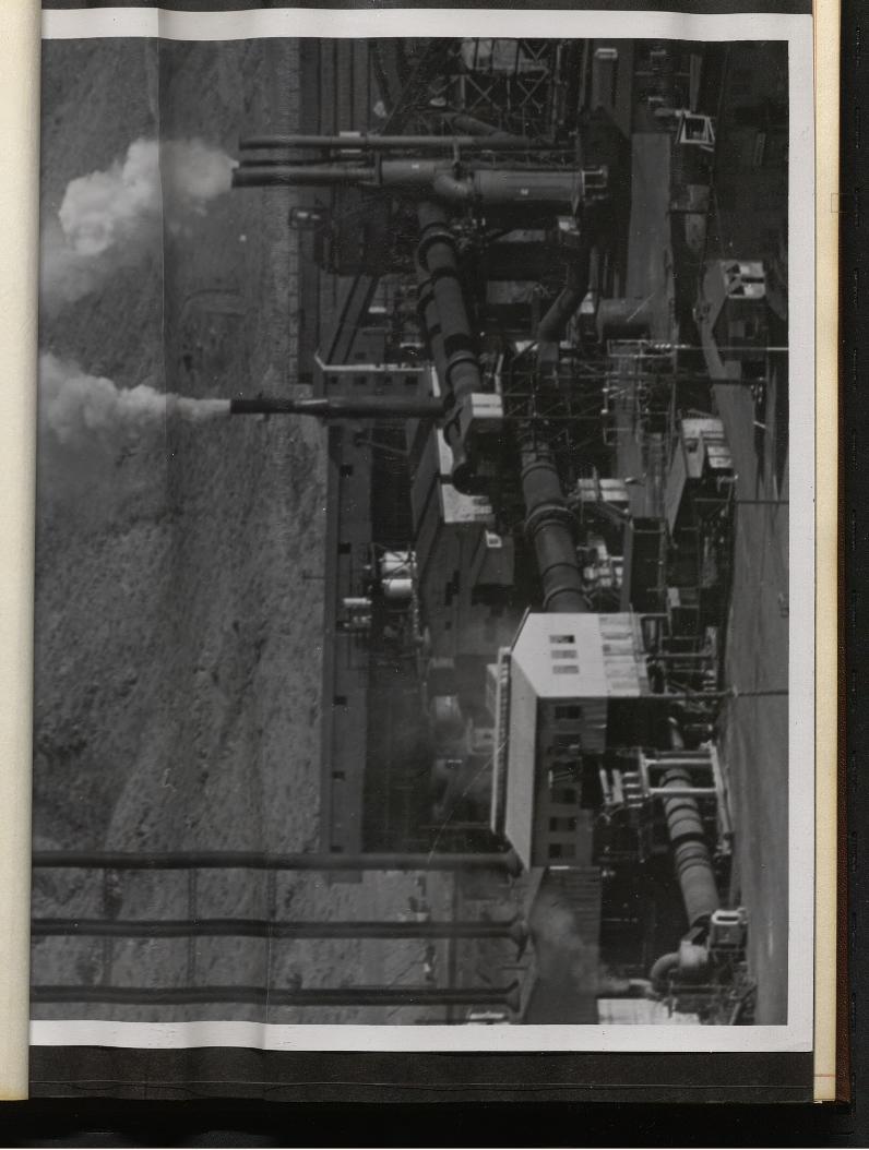
It was on this basis that the pilot plant tests were undertaken at the Bureau of Mines, Boulder City Station, Boulder City, Nevada. The appended table is a condensation of the various combinations of tests that were made and the assay results. A typical log of one test run is also appended to illustrate the means of obtaining data.
There were several considerations made when using this kiln, one of them being that the gas velocity and the mass velocity were very low. These low velocities gave very light dust loadings in the exit gases which might not be true in a big machine. Because of the small diameter (22 inches) heat transfer due to radiation would be different than in a machine with a large diameter and a greater ratio of length to diameter. However, it was attempted to keep the percentage loadings, by volume, comparable to a commercial machine, as well as to control the atmosphere above the charge. The following engineering data was used for direct interpolation to a large machine: retention time of charge, physical state of charge, nature and chemical composition of the dust, and optimum furnace atmosphere. Previous work accomplished by the U.S. Bureau of Mines was used as a guide.

TYPICAL DATA SHEET
from
PILOT RUN
Test No* 1 - NODULIZING
Date of Test: 19 October 1951
Observers: Manganese, Inc,Southwestern Engineering Co,
U* S, Bureau of Mines
Kiln Data:
Length - 231 - 0"
Ins, Dia, - 1» - 10“
RPM - ,5
Retention Time - 1 hour
Peripheral Speed - 2*.80 ft./min.
Fuel - P.S. 200
Draft - Stack
Loading - 8$ feedk% discharge
Charge Temp* - 160° F
Feed Rate - 350 lbs,/hr.
SECTION 1Part A
Frank Trotter
Joel Morris
Carl Merrill
U )
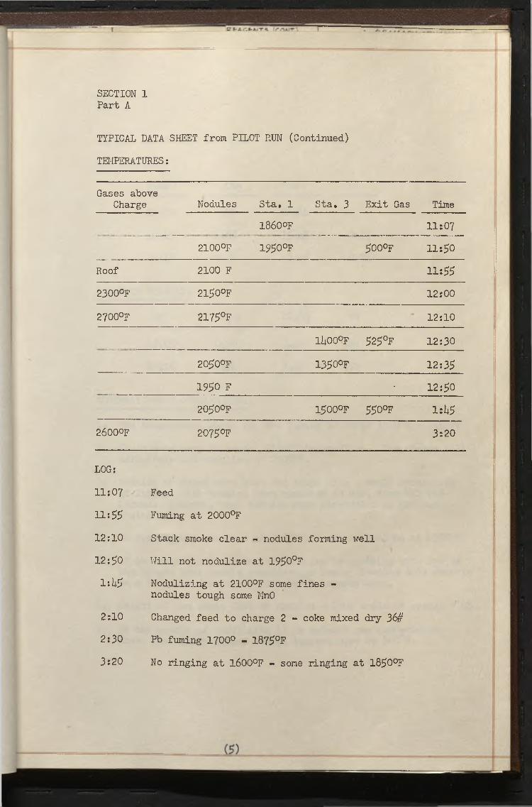
TYPICAL DATA SHEET from PILOT RUN (Continued)
TEMPERATURES:
SECTION 1Part A
Gases aboveCharge Nodules Sta. 1 Sta. 3 Exit Gas Time
1860°F 11:07
2100°F 1950°F 5o o°f 11:50
Roof 2100 F 11:552300°F 2150°F 12:00
2700°F 2175°f 12:10
1J400oF 525°f 12:30
2050°F 1350°F 12:351950 F • 12:50
2050°F i5o o°f 550°f 1:U52600°F 2075°F 3:20
LOG:
11:07 Feed
11:55 Fuming at 2000°F
12:10 Stack smoke clear - nodules forming well
12:50 Will not nodulize at 1950°F
iiU5 Nodulizing at 2100°F some fines -nodules tough some MnO
2:10 Changed feed to charge 2 - 'coke mixed dry 36#2:30 Pb fuming 1700° - 1875°F3:20 No ringing at 1600°F - some ringing at 1850°F

TYPICAL DATA SHEET from PILOT RUN (Continued)
GAS ANALYSIS:
SECTION 1Part A
Time C02 0 CO
11:50 % 13.5/2
12:55 5.6jS 15.6$ 0 ,1 %
2:10 6.2/2 13.6$ 0.2%
ASSAY OF NODULES:
Mn sl°2 A1203 Pb
58,05 10*90 3*56 *66
58.15 10*95 3.59 .91
OBSERVATIONS & CONCLUSIONS:
1». The temperature range for the fuming of Pb is l650°F - 1950°F
2, It is necessary to reach 2100°F to nodulize, The charge will definitely not nodulize at 2000°F.
3. Nodules produced were hard and tough with a small percentage of fines. When nodules were quenched in H20, some MnO was formed. However, when nodules x«5re air-cooled no MnO was indicated,
5. No ringing was observed at 1600°Fj some indications at 1950°F.
5, It is quite difficult to cool nodules by spraying with H2O as the larger ones retain considerable heat. Feeding this materia on a belt would be difficult due to temperatures,
6, Weight of one cubic foot of nodules - 130# angle of repose = US'
7, In the course of nodulizing it is evident gas temperatures above the charge exceed charge temperatures by 500°F.

I
RESUME OF TEST DATA ROTARY KILN
Coke Cl h e a d s C A L C I N E NODULEPb Mn Pb Mn Ketent.
Timel crap. Excess
A irLeading Gas
Exit TPb Mn Relent
TimeTemp.°F
ExcessAir
Loading GasExit T
5%- 3/16” 3.1% 36.8% 3.25% 44.1%1 3 min. 30 min. -1100 “F -600% 5%-20% -400*F .78% 48.10%- 6C min. 12100 150% 8-4% 500 °F
5%- 3/16” 3.08% 36.2% 2.45% 40.77o 40 min. - 1000°F -230% 11% *350 F .78% 48.10%- 60 min. 12100 150% 8-4% 500CF ■v
2-1/2%. 3/16” 3.24% 36.0% 2.81 % 42. 1% *60 min. -1100 °F - 1 1 6% 8-10% -400‘F 2.27% 46.5% - 60 min. *2150 170% 10-5% -900°F
5%- 3/8” 2.74% 36. 3% 2.87 % 41.5% *60 min. -1100°F -350% 6-5.1% -40 0 °F .68% 48.7% -100 min. *2150 20% 13- 6-1/2 %-1100‘F
6%- 3/8” 2.74% 36.3 % 2.54 % 40.8% *60 min. -1000°F -12 G % 6*5.1% *500 F .68% 48.7% -100 min. 12150 20% 13- 6-1/2% -1100 F
001wC> 2.78% 36.8% 2.97% 40.0% *60 min. -1000CF - 30% 8 w 5 -10.4% t700°F 1.34% 47.6% - 100 min. *2090 20% 15- 7-1/2% -1200'f
7-1 / 2%-3/8 " 2 .63% 37.33% 2.13% 40.0% *60 min. - 8G0'F - 20% 8-11% *200“F .62% 48.5% -100 min. *2090 20% 15- 7-1/2% -1200 °F
4%-3/8 1/8” 2.62% 36.4% 2.52% 40.2% *60 min. - 800*F - 20% 8-11% *20C F .47% 47.4% -100 min. *2090 20% 15- 7-1/2%-1200 F ’
3-1/2 - 1/8”_ CaCl .
2.62% 36.4% 2 .52% 40.2% *60 min. - 800rF - 20% 8-11% *200’F .87% 47.2% -100 min. 12090 20% 15- 7-1/2 %-1200'F -
1.5% . HC1
2.63% 37.0% 2.66% 40.5% *60 min. - 800' F - 30% 8-11% 1550 F .39% 46.85%-100 min. 12100 20% 13- 6-1/2 %-1400 F
6%___2L5ft£.-
2.63% 37.0% 2.53% 40.25% *60 min. - 850"F - 20% 8-11% *450°F .40% 46.80% -100 min. 12100 20% 13- 6-1/2 %-1400°F
\7.)

SECTION 1Part B
CHEMISTRY OF THE PROCESS
The finished nodulized product must meet the following specifications: 3/
1« Maximum of 15$ combined Alumina and Silica2. Maximum of ,12$ Phosphorus3. Minimum of h$% ManganeseIt. Maximum of Iron5. Maximum Iron to Manganese ratio 1:106. Maximum Copper, Lead and Zinc - 1^7. Maximum Copper .25$8* Not more than - 20 mesh9» Be agglomerated into solid masses
The concentrate as it comes 'from flotation will not meet these specifications, as it contains about 2»$% Lead, and it is from U0£ - k2.% Manganese.
The rotary kilns have six principal functions which result in the production of a satisfactory product. They are as follows:
1. Evaporation of water2. Removal of reagents by combustion3* Fusing the fine concentrate into nodular masses
Partial reduction of manganese mineral5>. Reduction of the gypsum contained in the
concentrate6* Reduction and volatilization of the lead
contained in the concentrate
The last three functions are chemical in nature and are outlined in further detail*
A. REDUCTION OF MANGANESE
The manganese in the concentrate is in the wad form. It is mostly manganese oxide with some percentages of the other oxides of manganese present. Uhen in a reducing atmosphere, as provided by coke, and at temperatures of about 700°F and above, the minerals of manganese that are present are reduced to form a series of manganese oxides, including M112O3, M^O^, and Mn02* There is a limited amount of MnO formed. It can readily be identified by its bright green color.
(8)

SECTION 1Part B
CHEMISTRY OF THE PROCESS (Continued)
B» DECOMPOSITION OF GYPSUM
Gypsum is decomposed to form calcium oxide at 1200°C« h/ This same reaction can be accomplished by the addition of coke at about 800°C, This calcination results in a weight loss of almost $0%, and inasmuch as there is sometimes 10^ by weight of gypsum present, the concentrate is upgraded considerably by this reduction.
C, VOLATILIZATION OF LEAD
The lead in the concentrate, probably exists in a complex mineral form, %] It could be loosely bonded with silica or alumina. It is the author*s opinion that the lead is reduced or partially reduced* and reacts with the gypsum and other sulfate minerals and is volatilized as lead sulfate,
Due to these reactions the manganese concentrate is 'upgraded from 11$% to 120% of the manganese assay of the concentrate,

SECTION 1Part C
CONCLUSIONS OF PILOT PLANT UffiK
A* BURNING OF FLOTATION REAGENTS
No difficulties were encountered in burning reagents and evaporating water# It is necessary to maintain a supply of preheated air above the charge to be calcined to insure combustion of reagents. At times it was impossible to operate the kiln with the burners off, only using the fuel in the charge for heat to evaporate water. It may be possible to operate the large kiln without a burner for similar periods. It appears that a temperature of about 650QF must be maintained to keep the volatilized hydrocarbons burning* By calculation, if a slurry of 60$ water is fed to the kiln, the burners will have to be used and this would require about 2 GPM of fuel. Unless a kiln is purchased especially designed for handling slurry, the slurry might run half way down the kiln, as was experienced in the pilot kiln. This would cut the retention time in half and create an intolerable operating condition,
B. TEMPERATURES REQUIRED
The base nodulizing temperature was between 2000°F and 2100°F for the sample nodulized* If the silica and alumina exist in a higher percentage than 1 1$ - 12% in the feed, we would expect that the fusion temperature would be lower. Temperatures which exceeded 2000°F produced a nodule which was completely fused and more brittle than nodules produced at lower temperatures. The gas temperatures exceeded the charge temperature by approximately 700°F.
Calcining may be accomplished in the range of 1000°F without detrimental effect (see coke sizing). On the calcining operation it seemed necessary to raise the charge to about 1000°F before it was oil free. The oil elimination, of course, depends on sufficient retention time for combustion. A retention time of thirty-five to forty minutes yielded an oily product. With a sixty-minute retention time, the cake was discharged clean, dry, and oil-free.
C. EXCESS AIR
Preliminary runs were made without considering the percentage of excess air. It was decided to control the atmosphere so as to duplicate actual operating conditions.For economic reasons about 20$ excess air would be optimum, but the percentage excess air is a question of fuel oil economies and the capacity of the gas handling and cleaning system.

SECTION 1Part C
CONCLUSIONS OF PILOT PLANT WORK (Continued)
D. EFFECT OF COKE SIZING
When the coke was screened, and fine coke eliminated (minus l/8"), lead losses in the calcine were reduced to a minimum. It is indicated that sized coke, for example, minus 3/8", plus l/8", could be added to the calcine kiln without volatilizing lead, but without a doubt, a percentage of coke would be consumed. Generally speaking, with the exclusion of fine coke in the calcine kiln, the question of whether coke should be added to the nodulizer or calciner is a mechanical problem and should not effect the process. There are certain economic studies which could best be made in regard to coke during actual plant operation.
E. ADDITION REAGENTS
In the event it is necessary to add chlorides to effect volatilization of the lead, HC1 as a source of chlorine should be seriously considered in preference to calcium chloride. Hydrochloric acid could be combined with the manganese oxides to form manganese chloride, which would provide a source of chlorine without diluting the nodule as calcium chloride would do. Hydrochloric acid as such has proven effective in laboratory tests for volatilization of the lead. Due to the free energy of the components and their respective heats of combination, manganese chloride will react more readily with lead than calcium chloride.
F. VOLATILIZATION OF LEAD
An analysis of the fume collected identified the lead fume as about 70£ lead sulfatej the other portion being lead oxide, chloride, hydroxide, etc. The identity of these compounds is not surprising because at no time during any nodulizing tests were the temperatures high enough to eliminate any quantity of lead in any form other than chloride or sulfate. In order of vapor pressures, lead chloride is first followed by sulfate, then oxide.We can safely conclude that the lead in the Three Kids concentrate will have to be eliminated as chloride or sulfate.It should be noted here when chloride additions were made to the kiln, pink fumes of manganese chloride were observed at the stack. This volatilization of manganese could not be tolerated from the standpoint of lowering the product grade and also a product loss.

C P - A n ft* A I T A (rr\KLT'j
SECTIONPart C
CONCLUSIONS OF PILOT PLANT WORK (Continued)
F. VOLATILIZATION OF LEAD (Continued)
When considering critical temperatures, in reference to lead volatilization, it should be remembered that at about 1900°F incipient fusion of the mineral surfaces begins. At this point the charge is changing from a mixture of solids to a molten solution and at this temperature or point selective volatilization of lead stops. This is, of course, due to the fact that the lead is occluded in the molten mass and there is no longer great surface for the fume to escape from. The fact that the fusion point is a function of the chemical constituents of the charge, which at times may vary, probably accounts for the erratic results obtained in lead elimination. A time of an hour and a half to two hours was required for proper lead elimination without a chloride addition.
(12)

BE-A //•rtillf


I E t A C t / J T S (C O W **> r? t a
SECTION 11
P R O C E S S E N G I N E E R I N G
The process calculations necessary to evaluate the equipment and establish operating criteria are described in this section. Part A, a theoretical discussion of heat transfer in rotary kilns, is an attempt to correlate the work of many investigators and apply them to this specific problem.
The calculation sheets on the calcine kilns,Part B, include a heat balance and other data, such as mass velocity. The calculation sheets on the nodulizing kiln include a heat balance and make use of the equations developed in the discussion of heat transfer in rotary kilns to ascertain if the equipment is of correct size, Part C. It is the author's opinion that with this information an engineer who has general acquaintance with chemical and metallurgical problems could rate and judiciously select equipment for any process using rotary kilns.

R f r A C , f c A J T S ,'C O A !'
SECTION 11Part A
H E A T T R A N S F E R I N A R O T A R Y K I L N
The technology of heat transfer in rotary kilns is limited, in scope. This, of course, is partially due to the fact that the greatest percentage of these furnaces have been used in the cement industry. The technology of making cement has been developed from an Edisonian approach and, therefore, selection of equipment has largely been done with that philosophy. Furthermore, the kiln has had rather limited application and difficulty has been experienced in accumulating design data with universal application. In the case of a new problem, as in the calcining of manganese concentrates from the Lord Process, in which there is no previous operation to consult, the kiln must be tailored to fit the problems of a special occasion.
In essence, a rotary kiln is a rotating furnace, consisting of a large tubular steel shell, lined with refractory, operated at high temperatures. Heat is generated from fuel, such as oil, coal, or natural gas. These hot gases impart heat to the furnace charge and to the refractory linings. The refractories in turn radiate their captive heat to the exposed surface of the furnace charge and, by contact, give heat to the bottom of the charge bed.
The exchange of heat in a rotary kiln is then effected in three ways: radiation, convection, and conduction. These phenomena are complicated in our case by secondary combustion of the charge bed and by the complicated reactions of reduction of the manganese mineral, reduction of the gypsum, etc., and the series of reactions which end in the volatilization of the lead. The formula of Fourier, Stefan-Boltzman and others, require considerable thought before they may be used to estimate heat transfer rates. The usual formula used in stationary furnaces do not conveniently lend themselves to this problem.
Heat transfer in rotary kilns used in the cement and lime industry has been studied in great detail by Gygi 8/ 9/ and Gilbert. 10/ 11/ There have been several other engineer's who have evaluated these rates, both theoretically and practically. 12/ 13/ lh/ Unfortunately the equations in the literature are not readily adaptable to other materials than cement, such as manganese. Host people who operate kilns take no data and are chiefly concerned with their own problems and prefer to solve them in an empirical fashion.
SECTION 11Part A
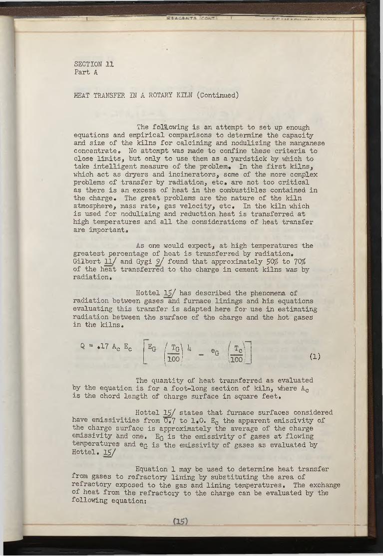
HEAT TRANSFER IN A ROTARY KILN (Continued)
The following is an attempt to set up enough equations and empirical comparisons to determine the capacity and size of the kilns for calcining and nodulizing the manganese concentrate,. No attempt was made to confine these criteria to close limits, but only to use them as a yardstick by which to take intelligent measure of the problem. In the first kilns, which act as dryers and incinerators, some of the more complex problems of transfer by radiation, etc. are not too critical as there is an excess of heat in the combustibles contained in the charge. The great problems are the nature of the kiln atmosphere, mass rate, gas velocity, etc. In the kiln which is used for nodulizing and reduction heat is transferred at high temperatures and all the considerations of heat transfer are important.
As one would expect, at high temperatures the greatest percentage of heat is transferred by radiation. Gilbert ll/ and Gygi 9/ found that approximately $0% to 70%, of the heat transferred to the charge in cement kilns was by radiation.
Hottel 15/ has described the phenomena of radiation between gases and furnace linings and his equations evaluating this transfer is adapted here for use in estimating radiation between the surface of the charge and the hot gases in the kilns.
Q - .17 Ac Ec EG j t g \ k(100 J (1)
The quantity of heat transferred as evaluated by the equation is for a foot-long section of kiln, where Ac is the chord length of charge surface in square feet.
Hottel 15/ states that furnace surfaces considered have emissivities from 0.7 to 1,0. Ec the apparent emissivity of the charge surface is approximately the average of the charge emissivity and one. Eq is the emissivity of gases at flowing temperatures and eQ is the emissivity of gases as evaluated by Hottel. 15/
Equation 1 may be used to determine heat transfer from gases to refractory lining by substituting the area of refractory exposed to the gas and lining temperatures. The exchange of heat from the refractory to the charge can be evaluated by the following equation:

SECTION 11Part A
HEAT TRANSFER IN A ROTARY KILN (Continued)
Q = .17 Ac 1 ~ Eq- + Ac.( i -
(2)
These equations evaluate the heat exchanged in one foot sections, perpendicular to the horizontal axis of the kiln. Heat could also be transferred by the hotter gases and surfaces being in proximity to the cooler surfaces. This is considered to be of small magnitude as the ratio of diameter to length of kilns is large and the absorbtive power of the combustion gases is great.
The refractory lining of the kiln is heated by the gases of combustion as they flow through the kiln. This heating continues until equilibrium temperatures are reached.The bricks are then cooled when contact is made with the material. As the kiln rotates the cooled walls again reach equilibrium with the gases. There is of course heat lost through the walls.
It seems reasonable to make certain simplifications to eliminate extraneous factors. It can be observed that a layer of charge remains almost stationary in relation to the adjacent lining until it cascades. By Schmidts 16/ graphical method it was calculated that the penetration of heat into manganese calcine is about 2 inches. As the kiln diameter is large, the surface of this layer, for practical purposes, can be treated as flat.
These assumptions indicate that transfer by conduction in a kiln is similar to the heat exchange occurring when a wall at temperature Tp, comes in sudden contact with a surface at temperature T2» A deriviation 17/ based on the application of Fourier's formula to this type of problem is:
Q = 2K ( Tr - TC ) f . H~ (3)V T T dT
where Q is equal to BTU's per hour per square foot of charge surface contacting the lining in H hours. The circumference area requires about one revolution to complete one heating cycle. The total surface completing a circuit in an hour is the circumferential area divided by the revolutions per hour. By proportion, since the total area of surface under the charge is Av , this area makes circuits per hour
H
Q = 2K A^ ( Tr - TC ) (10
V T T d t H

SECT ".ON 11Part A
HEAT TRANSFER IN A ROTARY KILN (Continued)
The transfer of heat by convection is relatively unimportant in a rotary kiln. Several investigators have calculated 9/ 10/ from 1% to 6% of the total heat is transferred by convection*
The standard formula 18/ given for convection between a gas and it$ bounding surface is:
Q “ UAC ( tg - tc ) (5)U - .01U Cp (G) «8
e' «2
U = Coefficient of convection heat transfer (BTU per sq, ft, per °F per hour)
Ac= Area chord surface of charge (sq* ft,)tg= Average temperature of gas
tc» Average temperature of charge
Cp= Spec* ht, BTU per lb, per °F.
G = Mass rate lbs. per sq, ft.
The effective diameter equal to four times the open area divided by the periphery.
The equations developed in the above discussion on heat transfer in rotary kilns will be used in the heat and material balances of Parts B and C to estimate the capacities of the various kilns.
(17)

I K E rA C fcA IT S (COAIT.
SECTION 11Part B
C A L C I N E K I L N S
HEAT BALANCE
Data Given:
Feed - 21.95 T/H ea. Kiln
Feed Composition - (Flotation Concentrate)
Mineral (1*0/ Mn) 11.35 T/H 385.0 lbs./minOil, Soap, Oronite 2.U5 T/H 81.7 lbs./minWater 6.95 T/H 232.0 lbs,/minCoke 1.00 T/H 33.3 lbs./minTotal 21.95 T/H 732.0 lbs./min
Reagent Composition
81.7 lbs./min
Diesel Oil Tall Oil Soap Oronite (Sodium
Sulfonate)
Temperatures
(a) Feed 70° F Product 1000° F
(b) GasesInlet to Burner 70° F Flame - None intermittant Exit - To be Calculated
Specific Heats
Gases .26 BTU/# °FMineral ,15 @ 70° F .21* @ 1000° FOil .50 BTU0 °F @ 70° FWater 1.00 BTU/# °F @ 70° F
Bulk Gravities
Feed 85 #/cu. ft.Calcine 53 #/cu« ft*
57*5 lbs./min 19.2 lbs./min
5.0 lbs./min
81.7 lbs./min
(18)

SECTION 11Part B
CALCINE KILNS (Continued)
Particle Size
80% minus 200 mesh
Type Kiln
Counter - Current
Kiln Size
Shell Diameter - 8* 0", 7’ 0" I,S, Refractory Shell Length - 130* 0"Volume - 3780 Ft3 Refractory 6" thick
Heat Gain
Diesel Oil (18,000 BTU/#) 1,030,000 BTU/min37*3#/inin
Soap (6,000 BTU///) 113,000 BTU/min19,2 #/min
Oronite (U,000 BTU/# est.) 20,000 BTU/min3,0 ///min ___________________
1,163,000 BTU/min
Heat Losses
(a) Evaporation of Water
232>#/min 70° F to 212° F
(1130,2 BTU/# - 38 BTU/#) = 1112,2 BTU/# (1112,2 BTU/#) (232 #/min) = 238,000 BTU/min
(b) Shell Radiation
Log, Mean Temp, Diff, Estimated @ U00° F
Area Shell (130") (TT) (8 ') = 3770 FT2
Combined CoefficientChart 113 A 3° (Std, Steel Corp.)3,3 BTU/FT2 HR °F
(3770 FT2)(3,3 BTU/FT2 °F HR)(I|00° F) -8,300,000 BTU/HR
138,000 BTU/Minor

R E rA C fc A JTS ACQKT.1 I - <■> r» . .7 , “
SECTION 11Part B
CALCINE KILNS (Continued)
Heat Losses (Continued)
(c) Loss to Product
(385#/Min)(.2U BTU/# °F)(1000° F) -
92,000 BTU/Min
Summary
Heat Gain
(a) Combustion of Reagents
1,165,000 BTU/Min
Heat Loss
(a) Evaporation of Water 258,000 BTU/Min
(b) Shell Radiation 138,000 BTU/Min
(c) Loss to Product 92,000 BTU/Min
1;88,000 BTU/Min
(d) Loss to Gases (by difference) 677,000 BTU/Min
Temperature of-Gases
8l*77r/M±n Fuel
© 30/ Excess Air 18# Air/l# Fuel
Fan Engineering Buffalo Forge Co,
(81.7#/Min)(l8#/#) - 1U70 # Air/Min
235 # Water/Min
677,000 BTU/Min = (li|7Q#)(.26 BTU/# °f )(T) +(235#)(.50 BTU # °F) T
T exit gases = 677,000 = 1360° FW
p. 538

R fr A C fc A JT S ICOAJT.j J—- A , *-» a u s jT
SECTION 11 Part BCALCINE KILNS (Continued)Temperature of Gases (Continued)
This temperature may be high as it is calculated on the basis of complete oxidation of the hydrocarbons. lie could expect some distillation, etc. and therefore estimate the exit gas temperatures at
1000° F to II4OO0 F
Volume of Gases
Assume 1200° F Altitude 1800 Ft.
VATR = (1U7QS* Prod, of Comb. & Air)(1000° F + U6Q°F)30///m o l U6'o'° F
X ('• 359 Ft3 / 1 (29.92 in)l /M0L! 28.~2~~
VAIR a 59,700 CFI-I
Vn20 = (235# H20)(100QO F +• U60° F )(339 FT2/mol) (2.9*92) 18^/m 0L U60° f 28.02
VH20 = 15,800 CFI-I
Total V - 75,500 CFM
Mass Velocity
Kiln Area * Ti 3*50^ = 38.3 FT^
Mass Vel. = (lU7Q(!/lIin + 235#/Min)(60 Min/Hr)W^~FT2
Mass Vel. = 2680#/FT2/Hr
This is a high mass velocity. 1200///FT2/Hr WOuld be about a normal value.
Gas Velocity
Gv = 73,500 CFM “38.3 FT2
Gv = 1930 FT/Min
This is a high value and will promote high dust loadings* A normal velocity should be below 1000 FT/Min.

Calculation of saturated volume & saturation temperatures calcine kiln gases after leaving scrubbing tower_________
Given: 7$,000 CFM © ll*00° F which is equivalent to lit7Or/ Air& 235 # H20
SECTION 11Part B
CALCINE KILNS (Continued)
Required:Saturated Volume, Saturation Temperature,Volume to I.D. Fan
1. Humidity of Hot Gas
~ 2^3# h20 _ #]_6 ji ^20/ # Dry Gasll*70# Gas
2. Total Heat Content/# Hot Gas
Water Vapor
Q = (CP)(H)(T)(W)
Q = (,U8)(.16)(lUOO - 32)(1) = 106 BTU/#
Latent Heat Water Vapor
Q = (II4.OO0 - 32°)(.16) «■ 220 BTU/#
A H Dry Gas
Q = (Cp)(W)(H)(T)
Q = (.26) (1)(1#/#) (11*00-32) - 3gl* BTU/#Total Heat 680 BTU/#
‘'*‘At adiabatic conditions the heat content of 680 BTU/# dry gas corresponds to a saturated ^as at 179.2 F., at 179*2 a saturated gas has a volume of 3 2 FT3 per pound of dry gas, therefore
(11*70# dry gas) (32.1*) - V @ 179.2° F
V © 179.2° F = 1*7,600 CFM
This is the volume of gas leaving wet scrubber & entering fan.
-"-From a standard psychrometric chart

SECTION 11 Part C
N O D U L I Z I N G K I L N
HEAT BALANCE
Given:Feed - Dry Calcine 838///min, 53#/Ft3 @ 800° F
Petroleum Coke 66.6#/min
Discharge - Nodules 750///min, 130///FT^ @ 2100° F
Required:
Pleat loss to product, radiation Exit gasesBurner Fuel Requirement Mass & Gas VelocityDetermine if kiln is correct size for heat transfer
Heat Gain
1* Calcine(838#/min)(.2U BTU/// °F)(800° F) = 161,000 BTU/min
2« Coke (assume 25$ combustion)(l6.6///min) (12,000 BTU///) = 200,000 BTU/min
3• Burner FuelTo be calculated
Heat Loss
1. Shell RadiationLog Mean Temp. Diff* Est. © 500° F
Area Shell = (l50»)(1?)(10») = 1+710 FT1 2
Combined CoefficientChart 113 A 50 (Std. Steel Corp.)5.5 BTU/FT2 HR °F
H = (1+710 FT2)(5,5 btu/ft HR °f )(5oo° F)
H = 12,900,000 BTU/HR = 216,000 BTU/min
2. Nodules
H = (75Q#/min)(,26 BTU/# °F)(2100 0 F)
H = 1+09,000 BTU/min

Weight of Air for Combustion
Assume 50$ Excess Air(20// Oil/Min) (21*5 u Air/# Oil) = # Air/Min
# Air/Min = U30

SECTION 11 Part C
NODULIZING KILN (Continued)
Volume Gas at Max, t and at Exit t
t MaxV @ 3000°F = (W//Min)(359 FT3/M0L) (3U60oF) (29.92" Hg)
30/r/MOL ij.60°F 28,02” HgV © 3000°F = la,500 CFM
t Exit
V © 1000°F = (Ii30#/Min)(359 FT^/MOL) (11+60OF) (29.92" Hg)3Qr/iI0L U60°F 28.02" Hg
V © 1000°F = 17,000 CFM
Kiln Sizing
Assume 10* Diameter
6" Kiln Block - 9'0» I.D.
Area Kiln Section - (li.5 ) IT
- 63.5 f t2
Mass Velocity
25,800 if Gas/Hr — --- = Mv63.5 FT2
= U06///FT2 Hr
This is a low value and will give low dust loadings in exit gases.
Gas Velocity
Vr, = 17,500 CFM 6 3 . 5 ft
Vq = 275 FT/Min
A low value which will create low dust loads in exit gases.

I g frA & fc A IT S ,'gQAiT.'/ ,tt r? • *. • A r-' >
SECTION 11 Part C
NODULIZING KILN (Continued)
Kiln Length
Using formulas developed in the section on heat transfer in rotary kilns, we will evaluate the quantity of heat that can be transferred in a chosen machine. In order to do this we will evaluate the heat transferred at 25 ft. stations in the kiln. The following is a profile of the gas and charge temperatures in a 10» diameter by 15>0 ft. long kiln;
Station
25
Charge Temp.
2100° F
Gas Temp.
3000° F
50 181*0° F 2600° F
75 1580° F 2200° F
100 13200 F 18000 p
125 1060° F 11*000 F
150 8000 p 1000° F
For example we will evaluate the transfer at station 25 here:
1. Heat Transfer by Radiation - Gases to Charge
Ql *17 Ac Ec e g/_Tq\u - eG / j r f1100.) 1100J_.
.17 (7.0) (.92 *38 ,/3U60^- .1*1* (2560 V*V 100/ l 100/ _
Q = 38,800 BTU/Hr
2« Heat Transfer by Radiation - Walls to Charge
Q2s .17 Ac 1 - Eg
ZLiTr \^ /Tc \^
\100J ~iioo / J
( 2 6 )

I gfeA& JfcAlTS (COAiT.'i _<h
SECTION 11 Part CHeat Transfer by Radiation - Walls to Charge (Continued)
^2= 6^0,000 BTU/Hr
3. Heat Transfer by Conduction - Halls to Charge
Kiln speed 1 RPI-I
H = .001+6 Contact time charge particle with
Dt = ^Eg cp
Drn — # 2 0
( 5 3 M
d t = #oiU5
q3 = 2 K Ay (Tr - Tc)
-\J it h Dt
Q3 = (2)(.20)(7.8)(*°2)
V JT(.oiU5)(.ooii6)Q3 s 93,000 BTU/Hr
U* Heat Transfer by Convection
Qll = u Ac (tG - tc) U = •0^ cpD .2
= (.015)(.26)(388)«8 (7)(3U60 - 2560) (7.5)’2
=5,600 BTU/Hr
Q2= (.17)(7»0) fl - .38
Area refractory in contact with charge =7*8 FT2
Inside circumference = 28#3 FtH ~ (7»8)(l)
(28.3)(60)
refractory
( 2 1 )

g fc A & fc A lT S tCOM T.'j
SECTION 11 Part C
Heat Transfer (Continued) RADIATION
STATION Gas - ChargeRADIATION
Wall - ChargeCONDUCTION
Wall - Charge CONVECTION
25 38,800 650,000 93,000 5,600
50 23,000 372,000 76,000 14,700
75 12,500 210,000 62,000 3,800
100 6,150 1014,000 1+8,000 3,000
125 2,U80 143,500 314,000 2,100
150 660 13,000 20,000 1,200
83,590 1,392,500 333,000 20,1+00
Average TransferPer Foot ll+,000 BTU/llr 232,000 BTU/Hr 55,500 BTU/Hr 3,1+01
BTU/3
Then from the table the total heat that can be transferred per foot of run is 3014,900 BTU/Hr
Kiln is l50>-0» long, therefore (150) (30l+,900) =145,735,000 BTU/Hr can be transferred to surfaces which is considerably greater than the heat required per hour as calculated. We can safely assume that a 10' X 1501 kiln will be large enough from a heat transfer standpoint.

g S - A C t A J T A L i»> r- . .. . ....\
SECTION 11N O M E N C L A T U R E
Ac Area of chord surface of charge - sq. ft*
Ar Area of refractory exposed to gas - sq. ft,
Av Area of refractory in contact with charge - sq. ft.
Bq Density lbs. per cubic ft.Cp Specific heat at constant press, BTU/# °F
D Diameter kiln - ft.
D' Effective diameter kiln - ft*
Dip Thermal diffusivity - sq. ft*/hr.
G Mass rate - lbs. per sq. ft.
Ec Emissivity of charge surface
K Thermal conductivity - BTU per sq. ft. per hr.per °F per ft.
H Time of contact of charge particle with refractory - hr.
Eq Emissivity of gases
ec Emissivity of charge surface re-absorption considered
eq Emissivity of gases at flowing temperature
Tc Temperature charge surface °R
Tq Temperature gases - op
Tr Temperature refractory - R
U Coeff. of convection heat transfer - BTU per sq. ft, per °Fper hr.
1 0 3 1 7 4

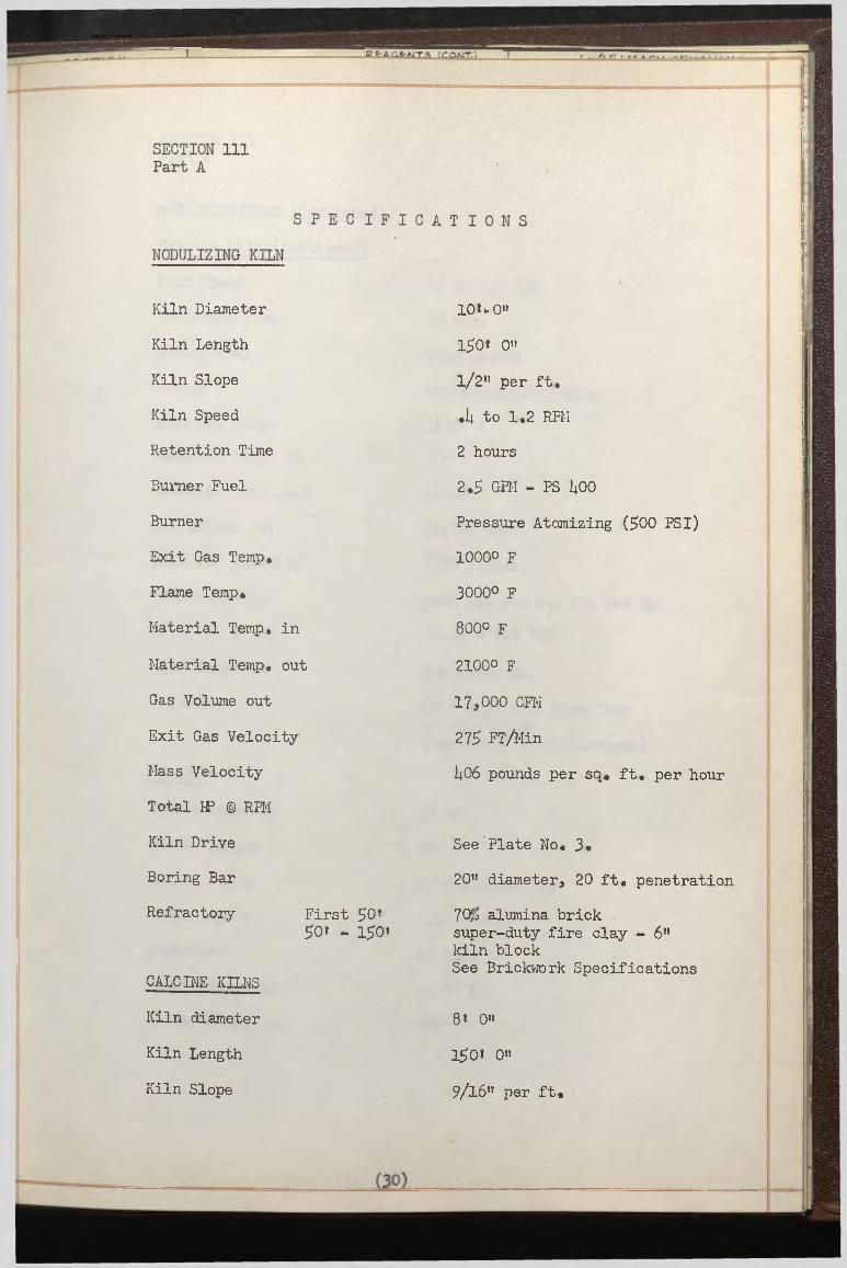
Kiln Diameter
Kiln Length
Kiln Slope
Kiln Speed
Retention Time
Burner Fuel
Burner
Exit Gas Temp.
Flame Temp.
Material Temp, in
Material Temp, out
Gas Volume out
Exit Gas Velocity
Mass Velocity
Total W © RFM
Kiln Drive
Boring Bar
Refractory First £0»50i - 1^01
CALCINE KILNS
Kiln diameter
Kiln Length
Kiln Slope
10U0"
150* O'*
1/2" per ft.
.il to 1.2 REM
2 hours
2.5' GEM - PS kOO
Pressure Atomizing (500 PSI)1000O p
3000° F
800° F
21000 F
17,000 CFM
275 FT/Min
it06 pounds per sq« ft. per hour
See Plate No. 3»
20" diameter, 20 ft. penetration
70$j alumina brick super-duty fire clay - 6" kiln blockSee Brickwork Specifications
8» 0"
150> 0"
9/16" per ft.
I R E * A_C.frA I T S ;coAIT.; ft r i m
SECTION 111 Part A
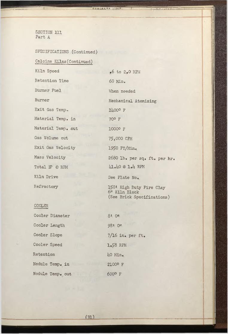
SPECIFICATIONS (Continued)
Calcine Kilns(Continued)
Kiln Speed
Retention Time
Burner Fuel
Burner
Exit Gas Temp..Material Temp, in
Material Temp, .out
Gas Volume out
Exit Gas Velocity
Mass Velocity
Total IP © RPM
Kiln Drive
Refractory
COOLER
Cooler Diameter
Cooler Length
Cooler Slope
Cooler Speed
Retention
Nodule Temp, in
Nodule Temp, out
.6 to 2.0 RPM
60 Min.
When needed
Mechanical Atomizing
li|00° F70° p
10000 F
75,000 CFM
1950 FT/Min.
2680 lb. per sq. ft. per hr. lil.UO @ 1.U RPM
See Plate No,
150* High Duty Fire Clay6" Kiln Block(See Brick Specifications)
8' 0"
981 0"
7/16 in. per ft.
1.58 RPM
I4O Min,
2100° F 600° F

JL E t A G f c A J T S ;C O K T .\
SECTION 111 Part B
CALCULATION OF SLOPE AND SPEED
of the
NODULIZING KILN
T = 1.77V 0- (L) *( S ) ( D ) ( N )
* U.S.B.M,, Tech, Paper No. 38U.1927
T = Retention time of material (mins.)
© = Angle repose material (degrees)
L = Length shell (feet)
D = Diameter inside lining (feet)
S = Slope shell (degrees)
N = Speed shell (RPM)
Slope per Ft. ____ S
l/U" 1.19°
5 /l6 " 1.U90
3/8" 1.79°
7/16" 2.087°
1 /2 " 2.39°
9/16" 2 ,6 8 °
5/8" 2 ,9 8°
90 Mins. Retention
90 = 1.77%/ U5 (150)(9)(S)(N)

CALCULATION OF SLOPE & SPEED OF THE NODULIZING KILN (Continued)
SECTION 111 Part B
Slope 90 Min. Retention RPM
120 Min. Retention RPM
3/8" 1.23 .91
7/16" 1 . 1 0 .78
1 / 2 " .92 . 6 8
9/16" . 8 2 . 6 0
5/8" • 7k .55
l/U" 1.85 1.36
5/16" 1.U7 1 . 1 0
It appears from chart that a slope of l/2 " per foot will give
reasonable speeds and consequently the power required to drive
kiln will not be excessive.
120 Mins. Retention
120 = 1 . 7 7 V U r (ISO)(9)(S)(N)
SN = 1.63

SECTION 111 Part C
CALCULATION OF
TOTAL HORSEPOWER REQUIRED
TO DRIVE NODULIZING KILN
Total Horsepower = Load Horsepower + Friction Horsepower
(1) Friction Horsepower
HP = (U)(bd)(td)(N)(F)(,0000110) rd
W = Vertical load on roller shaft bearings - in lbs,
bd = Roller shaft bearing diameter - in inches
rd = Roller diameter - in inches
td = Riding ring diameter - in inches
F = Coefficient friction oil lubricated bearings
N = RPM shell
(2) Load Horsepower
HP = (D X SINEQ)3(N)(L)(K)D = Inside diameter (inside refractory)
SINEQ = Vertical axis of kiln intercepted at center of kiln by a line which originates at the point where the charge surface touches the kiln lining bounds Q
N = RPM kiln shell
L = Length of shell - in feetK = o00110 based on angle of repose of approximately

SECTION 111 Part C
CALCULATION OF TOTAL HORSEPOWER REQUIRED TO DRIVE NODULIZING KILN
(l) Friction Horsepower
HP = (713,000#) (12',) ( 1 W ) ( <i92)( >018) (.0000110)U2"
HP = 5.35
Load Horsepower
HPar,= (9*-0» X .78)3 x 130» X 00110 X .92
HPa = U5.o
HPb = f(io*-o X .66)3 x 20i x .00110 X .92J
HPb = 5.9
Total Running Horsepower @ .92 RPH - 5o35 + U5«0 ~ 5.9 _ 56.25 H.P


" E t A ^ f c M T S ICjO K T :, IJ____
APPENDIX
REFRACTORY SPECIFICATIONS
i
SCOPE OF WORK
Work to be accomplished is as designated in the following drawings:
EM-U535-9.6-11 EM-[|535-9.6-l3 EM-U535-9.6-19 EM-U535-9.6-25 EM-U535-10.6-U EM-U535-10.6-5 EM-U535-10.6-6
PA 886-1
And (2) Two l£0» X 8> I.D. kilns - 6" kiln brick(1) One 15>0* kiln consisting of 112-1/2 of 10' I.D., 20' of 1116"
I.D,, and two sections 8*9" long tapering from 10t I.D. to 11'6" I.D.
(1) One rotary cooler 68* X 8' I.D.
CONDITIONS
The bidders will quote price for labor and supervision including all miscellaneous costs as to payroll tax, subsistence, transportation, etc. Bids are to cover complete installation costs: The rotary kilr etc., are available for inspection at the jobsite and the contractors are invited to make this inspection as no extra fees will be paid for special fitting and cutting of bricks.
All bricks are to be laid in a workmanlike manner by skilled masons and work is to be accomplished according to the following specifications
BRICKWORK SPECIFICATIONS
1. All employees shall be especially skilled for the kind of work for which they are employed and shall work under the direction of a competent foreman. All bricklayers shall be union members and belong to the local which has jurisdiction in the Las Vegas area.
2. Brick shall be dry before being laid.
3. For straight wall and sprung arch construction, brick shall be laid with dipped or buttered joints, as shown on drawings, then tapped into place with brick masons hammer to create thinnest possible mortar joint.
(36)
ICOA1T./
APPENDIX (Continued)
Brickwork Specifications (Continued)
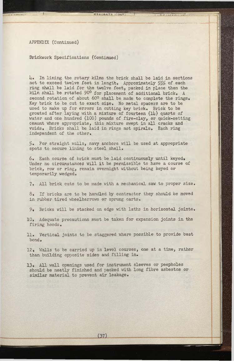
U. In lining the rotary kilns the brick shall be laid in sections not to exceed twelve feet in length. Approximately of each ring shall be laid for the twelve feet, packed in place then the kiln shall be rotated 90° for placement of additional brick# A second rotation of about 60° shall be made to complete the rings. Key brick to be cut to exact size. No metal spacers are to be used to make up for errors in cutting key brick. Brick to be grouted after laying with a mixture of fourteen (li;) quarts of water and one hundred (100) pounds of fire-clay, or quick-setting cement where appropriate, this mixture swept in all cracks and voids. Bricks shall be laid in rings not spirals. Each ring independent of the other.
5. For straight walls, navy anchors will be used at appropriate spots to secure lining to steel shell.
6. Each course of brick must be laid continuously until keyed# Under no circumstances will it be permissible to have a course of brick, row or ring, remain overnight without being keyed or temporarily wedged.
7. All brick cuts to be made with a mechanical saw to proper size.
8. If bricks are to be handled by contractor they should be moved in rubber tired wheelbarrows or sprung carts.
9# Bricks will be stacked on edge with laths in horizontal joints.
10, Adequate precautions must be taken for expansion joints in the firing hoods.
11. Vertical joints to be staggered where possible to provide best bond,
12# Walls to be carried up in level courses, one at a time, rather than building opposite sides and filling in.

I E t - A C t A lT S ICOKT.'j I
T H E P L A N T F L O W S H E E T
The Three Kids deposit of manganese was discovered in the fall of 1917* according to Jones, l/ Since that time considable energy has been spent by private industry and agencies of the Government in an effort to produce metallurgical grade manganese concentrate from the low grade ores of the deposit. All of these attempts failed to produce a metallurgical grade product economically*
The U. S. Bureau of Mines at Boulder City conducted large scale pilot runs using flotation as a means of beneficiation. They tried to de-slime the ore and float the various fractions with cationi type reagents. These runs were not successful. In 19U2 the Government financed the construction of a plant at the Three Kids Mine*It was operated by the M* A, Hanna Company. This plant used a hydro- metallurgical process where the ore was leached with sulfurous acid and formed manganese sulfate. The manganese sulfate was purified, then reduced in a rotary kiln to manganese dioxide. Due to the physical and chemical nature of the ore, the plant failed to produce a product economically, and was closed.
With the benefit of this past experience, the management of Manganese, Inc* decided that the only scheme that was economically feasible was bulk flotation without sizing or de-sliming«
Southwestern Engineering Company was commissioned to develop a means of beneficiating the Three Kids ore. This work was carried out under the direction of Mr. Robert Lord, Chief Metallurgist.
After several hundred tests were made, a successful combination of reagents was developed.
The following tables give typical laboratory results on ores containing about 2$% manganese and 195 manganese.
TYPICAL RESULTS ON ORE OF 255 MANGANESE CONTENT
% S] 0 25 Distribut:
Content Wt. % % Mn % AlpO^j of Mn
Assayed Head 1 0 0 . 2U.39Calc. Head 92.7 2 5 . 0 2 1 0 0 . 0Re-Dried Concentrate 1*9 . 2 h 3.59 9.25 2 .0l* 8 5 . 8Cleaner Tails 1 U.5 11.07 6 .1*Rougher Tails 29.0 6.73 7.8

C t A C f c A J T S (C O M T.) T
The Plant Flow Sheet (Continued)
TYPICAL RESULTS ON ORE OF 19% MANGANESE CONTENT
% AI2 O3% Distribut
of MnContent Wt, % % Mn % S1 O2
Assayed Head 1 0 0 . 18.92Calculated Head 90.7 1 8 . 8 6 1 0 0 . 0Re-Dried Concentrate 33. 1*3. 7.60 2.15 75.2Comb. Cleaner Tails 25.7 1 2 . 2 2 16.7Rougher Tails 32. U.77 8 . 1
CHARACTER OF THE ORE
Practically all of the manganese oxide is porous, brown,2/ earthy wad. The ore has tremendous surface and according to Hewet is a sedimentary deposit consisting of wad interbedded with lake or playa sediments belonging to the Muddy Creek formation of the Pliocene Age. The manganese minerals other than wad consist of minor percentag <£psilomelane and magnetite. The gangue is composed of quartz, gypsum feldspar, tuff, micas, clay, opal, strontionite, There are also small percentages of lead, copper and zinc. The table below gives an analys. of three stock piles of ore.
ANALYSIS OF STOCKPILES
# 1 J inJfC #3
Mn 29.5 2 i*.i 1 8 . 2Na 1.3U 1 . 0 1 1.1*5K 1.96 1.77 1.81*Ca 1 . 0 0 1 .1*2 2 .1 1*Mg 0.92 0 . 8 6 1.70S 0 . 8 1 0.65 0 . 6 0sl° 2 25.15 32.25 1*2.25AlpOo 5.65 7 . 0 0 8.50Fe 1.35 2 , 0 2 2.07CO2 0.61* 1.23 1.07
Loss on ignition 1000 C
Stockpile 67.1*1* lbs. cu, ft.
The laboratory tests were followed by full scale pilot flotation tests which confirmed the laboratory results.

R f r A C f c M T 5 (COKT.'j ! - t> V \ M A r*^r v e? i i «
PROCESS FLOW
As indicated on the appended flow sheet the plant is sized to handle approximately 1U50 tons per day of ore containing approximately 18$ water.
The ore is trucked from the mine and dumped into a hopper feeding the primary jaw crusher. The five inch crusher discharge is fed to a rod deck screen where the screen undersize is fed to a belt conveyor and the over size is fed to an impact crusher. The secondary crusher product is also fed to the same belt and is conveyed to blending and bedding bins. The ore which is now crushed to 90$ minus is fed to rod mills in closed circuit as shown on the flow sheet.
The ground ore which is about 90$ minus 200 mesh is then fed the conditioners where the following reagents are added per dry ton of mill feed:
Diesel Oil 1 2 0 #/Ton
Tall Oil Soap W / T o n
Sodium Sulfonate 7 *i|#/Ton
Sulfur Dioxide 8 .5 #/Ton
These reagents with the exception of Sulfur Dioxideare prepared in a special plant where they are metered with proportioning pumps then emulsified as a water phase emulsion which is then pumped to reagent storage. The Sulfur Dioxide is metered to an absorbtion tower where sulfurous acid is made continually and added to the circuit.
The pulp is conditioned for about 1$ minus at l£$ solids. It is then diluted to about 10$ solids and fed to rougher cells, this rougher concentrate is cleaned four times.
The reagents probably function along these lines* The sulfurous acid reacts with manganese dioxide to form manganese sulfate. The manganese sulfate reacts with the Tall Oil Soap to form an insoluble manganese soap. This soap deposits on the mineral surface, which is then in proper condition for flotation.
The soap acts as a collector, the oil as a surface conditioner, and the sodium sulfonate is an intermediate agent allowing froth formation.


R t A C f r A j T S (CO/MT.; ! - t> V ? AA A
APPENDIX C
L I S T O F D R A W I N G S
Page
FLOW SHEET 1*2
PLOT PLAN 1*3
CALCINING KILNS 1*1*
NODULI2ING KILN h$
NODULE COOLER 1*6
CALCINER DRIVE 1*7
1*8NODULIZER DRIVE \

A t IO A!
fgLidAg C B U S H IA J Cf OPMAT >OM
J 9CHt S O ,
r
r— z
i « c .
■" ■ » r ^ .ico— 1—gJ
J LL-n
r / Z U ' - g i P i E C - KEACE-AJTS
FUEL S K TANK,
'4 - E M U L S I F lt D R tA C fr A JT S (COA^T.)O R O A JlT E - P l
m» S O L TAAJK 4 AC IT lire TAaj< 4 A C IT.• < TAAJK
lOAJ P HEMULSiOAJ P(IDPuMP£■ v u l s /o a i p e e p p u m pE -M U L S IO A sJ S T O R A G EB o i l e r s
a :
f M U L S IO A J TWAaJSF frR PUMP3t„M.> TAKlK « Aft! t a t ©*.FUEL 0»U
Al ' ?
_ L & „ J KC G
©^ q m p a R Yrg U S H IN S ,
l - C t - J
i*----------------- J
[ 1 A M E Lirn«vkva
I_____S E -C TIO M ,
\ & j BLfrAlDlAJG i
J S T O R A G E - ,
JJ t _ . J S £ -. © s RI c ’. 'M -■
M MK%/Dl*y P»»MkiOH
+f? *l i o . j T
r “
l i ~ P -tlw ____ . “ ria l _ _L _ i f ____ i _ l ^ ir
*1 3 M I
L----- CEL,*1
I s
f l o t M ~ i o a j
n
< 0 3 -
i ; -g A lt g Q A D 3ISIAIGSb o i l e ru a j l o a o i a j g p u m p s ,SOAP TAMK3 OBCJ/Tt TAAJK, S U L P H U R UAJLOAOlAJG NODULE- ApKtr/sic a * f -u e -K ca* p j „ . «
C O K E , U A JLO A D IA j G M C O U l f r L O A D IN G WATtK SGPTE-^t-R LOADING S P O U TS U N LO AP IAJC S P O U TS UAJLOAOIAJG S P O U TS IC A O fA JC S P O U T S OIL St O<»A(," *ANK
P r i m a c y c c u 5 h i a j 'j
- S > C O M & A g , T f c U S M I A J O T>c pjuiv Ijp ViiGH,»,c>Miria 6 a c m o u s i
M A GAJfr S C 8 M .I M P A C T e , B t A K I R
C O A I / I V C R c o A J V l y o «
AiOTE-:2 C -C T I O A J 12 R kC -P LA CfrD f tV L I Q U I D S O , . P LO ta/ D IA G R A M SWOW/AJ F O P . F U T U R E - G O A IS lD f rP .A T 'IO A j
§ V N R a £ 5 5 v C 6-s implex vtriAu • Du p l e x v e i i a i s ,
r .. T3 - t Z m p l : aj <s
J _4 - B L 8 A I S ; M G t S T O B t S t
i i
i ~ CC5 AJ V f V O R IP j “ E O D I N C
L £ - q ErAJ DQ U A A l S W O W N T ^ a -5 f i r . Tta A lS /b f 0 8 C P M */ATER O P M O IST - C C L
T 5 M -n Tt>A43/hr S O L ID S ^ O / ? GrT»fY) P u l p S A------ ------- r»----------------- , l Sr MAI
■ -• F
I F I I O C R S
^ Or B 1 /J S
VC5R- S B : .N c
lT 'J R A 5 »& A C M O U :BAG H « U I
S O L I D S O P , P U L P ■ B A S E 'S V A P O R S O R S T C A M
WATfcfc,F u t u r e - IA J 5 T A L L A T J O A J
. . , ________i t fi F t MAIAJ W ATER
J F W A T t P “ *I P U M Pft? Me-
S^STCHBLC* TAAJK) T A A I K SH E A D T A N K SE T » R _____ !
S P E C Gff. M E T E P S PLOWMf-T^-R 4H MSrlffl.
T O r-g J
-rf #• I
SS/6-'4 ° T14*— --— ---: t->
U f c u r
3 & c t ;c; m ( iT ) t a i l i a i g s h a ^ d l i a ig
r“ P - ~ i ~t©=? *>’'S r/ ®
i i S i
r v 5 ?
- n /06>
i?
S'
i o*t
HVV*-T F
4 M « r £
/ r S r t
« — —*O ^Q
,, K i*.
^JrS
!a£=
r / .< r
— i— AA2 G U {[
~7^T7
JA L.
t L
n
S & C J IO A J
!OA4ri-fv * “ "
L.
_a«!L
:x:
r ■ D — •!
Is 11 F«
8 S ' j
ScT lT r 5cZ
. » ^ b
i i i ii i
J . _ _ G l W W I I j f -
SAIt
If' 3 S -C T I OM ©
.ADH A A J p L I A jS i-
FCE-SH H ;D
/OQ6**> & TO AM/
-717
{ Li ' r
$ - 1r--<y v jL Jjf•oeei □ 100 +90 0 0 _ _j~Tc'* oc**IOU Q S___ _____
I I
o £~CTIQAJ
0 gD U 5 T HAAJPL1 AjC ^
S<9C6 -'*•» *• 7Alox 7}jf.R -ORi
I PKtSH AxC Ma^T'uV -
S E -CTIOM- - - -L-U
^ . ^Pi
, 9Pt9n‘ J U L
_____j. . 9* '
tT Q » L m« « , i L A L G i N I M S
______ 9F FCOM T - A ^ H t O
T (U (E> (£i ® iV O O 9 B M T)
P 9&
9JJ L - Q *— Jr t 1 ---- ----------------T f c - ------------------- ----------- 1j-H h -4 — -----------------------i i . B r
/r* ’3IU 9XF
= = » j j , ------------------------ ----------------------
3 L L 9W
■7T/.S A I jp .a r
z m
M IL A , I: ' ‘t J f i
r / ^TIOAI
u(____ J / r r
^ C O JC e -A ITC A TErTH ICK. EM IAJG
* g a t . _ L f■9ST
”5i
I5Rl« T -~- ^ _
3 & C TIO M
®4ILR OA& S1P!/
0CT“^TJ
IJ6
_____________ P L O T A T I O A lT u m pA S M P u M P 3 U BQfc- TAAJK.w e i c x s o xC C T A J D l T IO A J I R S C O A J D I T IC S A J C K S R O U G H t R S g c a U « H t P 3 T A I L S S U M P S T A I L S P U M P S i a r s t a g e c l i a a j i r s
J m i f i t f e a B
7 - C G ^ M C f c 'L l T R A ^7A ( 5 'P W O N TA N K .'
7 <- | u J j t i S J L O W 1 P U M P ,«
F L O r/ M E -T Ws p . z x . M rre -RS P R A Y P U M P S pM MfrTC-R.
e T H i C K F a J i 7 T S -
?s
r m g i r S i L & i - 1Fees p u m p sS r t ACV H E A D TAAJKxiL'fgy/ BOXF 1 L T R A T C BSCIEV'fcJ F ! L T H A T E P U M P *M O I S T U R E - TP . A PS
A - . P l L T g A T ! O A s I
V A C U U M . P U M P S - S ^ T A N K S ___________
c a l
N V E / O R IA ILA JS aULlXIAiC Kit-AJ
z& n rlR f* *B l o w e k o v e r p l o w tahvc
S E A L TA A JK P U M P F L O W M t T E R S P . O f t . M E T t P l
4 T f ^ D j ^ ^ v 5 3 -. R u S m b S .
■t o p ? A C e-
F A AJ F A Al S T A C K S T A C
U M '
P -D U B T H A M P U IA IC| 5 S ^ T a S 5
v - (r e «
LOAD eg. . 8LL s cAlB___ _
C K
p H f t ,T A C K
/O TtOUlo wIOAIOV IO X! & 5lODD MtAO 1 I OCA M-.r*lOFFf *"* ■“Bfi.
c e n t pum pF L C iW ' M f T i R F L O W M E T E R f l o w m e t e rC t .M T . P U M P -----MP
S V P H O A I T A A I K TM I C K I A 6 Ra a s i s e t s » s a a Et a i l s p u m p
i M P U M P
~?P- T A I L i A l G 5
Itf lfB
iiinsiuMiO V E ftfL C a W P U M P
: z - M l S O , P L A M T XSfrfrNOTe-)w u f t e i aj 1 2 A* I B l o w e rF t f o e r
C R U S M I R B U C K E T E L E V A T O R B lMW t l C H T O M E T t RS U L P H U R B U R A J E R A B S O R B T IO A J T O W E R A B S O C B T 'O A J T O W E R P U M PE X IT -G A S S C R U B B E R
_ T A C KC A S C O O L E R Mt S O * S T O R A G E H i SC5* F E E D P U M P H i S O , FEED P U M P H i S O , T E S T
• fcrv P U M P 12AA SOt ST0KA6e TA N K IE M SOt PUMPie c c 6 o » co*r>*e*aotL
15-C O K E MAAJDL t /sIG
SftK t T E L E V A T C a R *3 L “
14- &MUCSIFieD R E A C T SE M U L S I F I E R S E M U L S I F I E R S ^ A IL O A DIAJG P U M P
D I E S E L S T O R A G E T A A J K . ‘ g O A J I T E S T O R A G E T A A IKO RCvm
S O A PP '* Z Z
„ ____P U M PP ^ P -
m v i i i o minn ■ lull■ * ins pnoranii w
SOUTHWESTERN ENGINEERING COMPANY
M AN G ANE SE, INC.PROCESS FLOW SHEET
V
42

v _
0
tMULSMtP KeKfufs
@
b
tAHE <t 9Es.t&c.k>iuc cHh
$' u
,!K‘ACA ■ATS- . :.r..W'.VA\ ToX
HIHI______i
-------- 9 J .
HODULES tM P U H C
1 N o C U L I Z I H C H U M
______il
r -i___ _
__________l
Mn DoS>T
~
© itr1I
%
:**- c *Kfg jf/ij/3 < J
w =P l Du s t
Mii Du s t
Jr
~ l
__________ I
S O, TIUHA
iufctiwriaw Cwt Ai*2D
" I
/
L J
F-i r « t A i d
I-------- 1 I---------------------1| C U A A J G * -
M o u a t
i__________ J
7vu r^^™jf cw« tut
I £*** A Yr - - j u tI K : . V
O ficc* <•3h©P BuilDIAsiGy
/A y
f c .9 < V .
S u b s t a t i o n
cant mAmdumc
® f
&e-coijicpua w w a
A-fPAMf
— Oi
/
* = - 1
S u b S t a t i o a i
i _
r riI ^ f l o t i p o u A u t l d i n c
□
v5t?
( h
, _ J J
L J_____ s i .
© © <D t o
IM
/ N . D E - X \f P R . M A R Y C R U S H I N G :]2 S E C O N D A R Y C R U S H I N G j3 S A M P L I N G -4 B L E N D / N G 4 S T O R A G E -3 G R I N D I N G<2 F L O T A T I O N j7 C O N C E N T R A T E T H I C K E N I N G ;a P ! L T R A T / O Ns> C A L C I N I N G10 D U S T H A N D L I N G s|h T A I L I N G S H A N D L I N G jr z S O t I13 C O K E H A N D L I N G !14 E M U L S I F I E D R E - A G E N T S
Jjtoc,'HP/Lt
r p
PRIMARYCAUSUlUG
{ f t
| £ 1
* < +
M4 3 3 3 I G - I P R IM A R Y CRUSHING M 4335 -Z .G -I S E C O N D A R Y C P U S HI MG M4$}3 - M 4F 33-744333- 3 G-1 G R I N D I N G S E C TIO NPl4333-c.-a .-i f l o t a t i o n s e c t i o nM 4535 7.6 - / COHCBHTRATE JH lCH E H IN G M 4G33 -&.C.-1 F -ILJP i&POKI M4333- & G - Z F-n-TRATiOS/M 4533- ‘) .G -Z CAlC/H/NG M4333- ? G - 5 CALCINING M&535-9 G -3 CALCINING M 4333 -IO .C -4 D U S T HA HOLING M 4333- 10 .G - 3 D u s t h a n d l in gM 4333 - //• 7- J TAILINGS H A N D LIN G M4535 -/2 -7-/ S O t M 4333 -/ 3 .G - / C O K E H AN D LIN G M 453S-/4 . G - / EMULS/P/SD P>E -4G F N f ^
.0 2 -4 '
4 -3 5 - 0 'U Vc»eiHM-RIVH/cwf DWfc f*cm l? t~2
A U U S 33 sa r-
More-:FOPr fiftRANZBJJSNrOP TWCKSfJep
SOUTHWESTERN ENGINEERING COMPANY 4*00 Santa re AvtjLps anom^ caajf.•as sagg.’vaas. rs s.; gsa&ggtrsaejy araar
M A N G A N E S E , I N C . : 43Do Not Scale- follow dimensions GENERAL PLANT LAYOUT

.i/A
pc/s
A /p
up-
P~
<x
ccM
uro
uu
-Ar'
OP
-r -5
e£J3
tPtf
.M4f
?3 9
- s- 3
_, _ f tJopuuziuej Knaj
1
AAui-4AsnJc,*!jr
-Vgf/^5*---- O o e -p^-—
JS-c.'
itfSTKlMrdT B O A R D I
+
i---------------- --------------
/3-3 /3 -0
~ r
, J' OF- 3 - 0 * X /9 0 - 0
P&FCALC/tJ/KJ<j X/Z./V
u -
r-J-&*9P__ _ . ... .rdri.. i—
^5w )>
,. o r -a -o " * x / f o 'o “___- PspcALd/puuq k/lu
€ D « r » Q9>»s e*K>'fJe
P P P -C A LC U U H JC . P tP lU q r -L o o R F P A M t u q
AN O T f -
S A S W A S P P P S ( J O T S t J O p 'Ur u P L A U S t P D P W q .K f M 45SS-10 .0 - 4
o PZ.A.V
—i
i0?10_J l
>T0I
S P U T T P r R COIUK PVO /Z
OP/PYbB. U-9A
mz o - - ) n n p a i t m f i t s a i p u u p
:?o-ojk’/uc.exp.
i-o >9f-9fjt> ea;r p'ptt A4?f uiqt90 -/£ 'o' -
■SiP P P C A L C lU lU C KlLLtS >
POOUUZlPO K / u J ____D U S T P O O D
X
V
iW*
\3. ~Z.
/>-
o-JSA-’c.exP
j £ o £ j u c j * * _ .F'sxP.
M
*
..£1, :& o \ql
f L . TOP O F f COAJCKtJt a & o
KILU?
, 0 -/ • ,/./ qrouuD , /.mjS -0 J iE / 0 3 , .3 '-/
FL 1354- 7 TOP O F £>TF?L
P l . 1 3 4 6 -3 + TOP O P S TPP l
tL ./ S & o 'j
P
Q)
4 0 ! - I I f TO tTA IT P/P57 C A J P U U P
L _
CA/L.’tu q f ? p jR r-oP d b i u p p h u UODUHZtuq KILPI
- tL iBot-ii‘
PL./3Tf-4t
>r*'w/\TKiul
i o - fj"wtsrk»-tJ\ 'o'k'i'pAsfkiuJ
pi. 13)0 -o
n
..jOPOFspee*./B94-Q
TOPOF JTttL CL./3&&-Q ?
SrL. /&77- o i * l
N MX&ZUOUJt1
FL. JO P O F 3 T F F L '0 7 0 -0
Q.APPROVED FOR CONSTRUCTION
ceo$so\ tP PLijroeMfJJJB9&&V
" ©D /yM A S q p - P U D J ’P U U ! n o n
'J F O U U D A -lO Ur~ ’
90-0/
>>z- ;oj rq an?r ca?p Lnjtrr
, DC:\T. CUD feuuutoiu * 914' r -O U U D A flO JL I
:4 Z '-9 & ‘ r e 7A?7 XP?7BA?P U U P
H
P P P -C A L O U u J q k /ljJ s rD uar/4o o b s
p-L ./a o u -o -g
_________tzz-rs-zze-uce-________U 4 f7 f - 9-1-1 P P U O O L O P O L C K lLU P O W U C . F O P UP*/P1LU5 M 4 f }f -9 / -Z ZP M C IA L O P O LC POLPJDA7 1OK !PO P PSCULP COOLPX.WST** 9P1 D lJC U A K q P P U D T P u U io l : P o u U O A T ia t JM t w - 9i P4 D P /V P p77o T P u u U l O U F -o u U D A TtO LJ
M 4PH -9 .C -3 M /XPCLKtSTP : P X M A U jTP O O D P O U U D A T K n J tiSstS- 9 4 -7 C P O JS O X P P P L A T P O P M f STAtpP/AY m K S S -9 .4 9 P A IL lU Z 2 9 T A 1 P D P h P P U C U O D U L m U C 4,/LL.,\!463S-9.3-o A D .y p P P & U 3 P S JP tL PLPV < D P JA 1LS \ 4 t 3 3 i -9 .v r c o t u v e v o K *J° 9 a P 4 5 3 i -9 .e s S P L / T T P P C o l j Y P V O P .M 4535 - 9 4 -6 r P P C4LClUtL 'C P lP lU q P LC O P PPALt/L/q >44335- 99-19PCP-CALCtU/Ltq P IO M P P f B u p U P K S \«43S£-9<9-ia p p p -c a i c /i U/Oc; K ' l u s D u s t P o o d s4*4335- a e -II tJODL'L IZIKlq PM. U OUST POOD >(4355-10.9-4 q A S P 'A S P P B S F O P P P P -C A L C H U P P S
Q >:i.\PK POU5P ;P K P A L 'T P p o o d
*o u u d A7:o u
DO NOT SCALE-FOLLOW DIMENSIONS
S a g .t o l l CHWt-P LOCAJiOM OPMC-pPSZm
SOUTHWESTERrTENGiNEERING COMPANY
M A N G A N E S E , I N C .CALCINING- SECTION 9
ARRANGEMENT OF CALCINING KILNS
44
i _

I? *1 *1 °SOUTHWESTERN ENGINEERING COMPANY
4S 0 0 S A N T A P S A V I _ L O S A N G E L E S , C A L IF .t u b «»t.,3ssiww» sKMMrr8M8s»w®arM A N G A N E S E , INC.CALCINING - SECTION 9
GENERAL ARRANGEMENT NODULE KILN a BORING BAR L
AON DXnTt9tltJ '-K u tJlO U AfODULIZIUtjJUlU
SCALE-FOLLOW DIMENSIONSDO NO
i?
P L A fJ
Sre-e-L SUPPORT FOR. A "FRAMg- i RORnJG &AR
v c o o l s -r . P e -e o e * /c. ROTARY COOLSrR ) 92 y APR AWC ErMe-Mf
; 4 r *fc g*ff FJUff. - y*
to -P 'J-'tO -p 'U ciC -uLiZU/Cf A /LU L _
A Mi SHAf-f
//•JO ^JMST*tJ"t**r &°A*0 "7
V B /
14-4"
.
4-7 j z j - o " L_ f< »
1-0T
A a*1- - ‘PATfO FOAf CiSSKAXy*9t*J £UC rppiJKrpw urrcuL. Ziue kiuu ..
r-f-ry y R OVED FOR CONSTRUCTION

wMMRNNflMMMI

T
«Z
©^ _/P. ^! />g
A*/4 " r tss* sy -: c*r,c*. > /.<<'
/ ✓ r ts S'
r * & c -*■ ^-v' ^ .•;
®
-f/zc e><«--~ ^ ^ /y
'c 3~c> *s> /*?*’r-o«;, S~0+ <s~4F*CJ * T £ > < s s s C?. . /V.y //<#>.■/
S ~ s > ^ ^ r ^ > S ? * r O es < r* r* ? . " ■ & * -^ S ? SV._J / / < ? . V
•? "<r? 6 <z> ■•svts. ss? "s-*v<rsr s o x-w*, ^ <5 Sir r S "c~. -?<£> ‘ " £ 3 . S'^
■<?«? <5 /*■? O <* X / V ^
# » - //s-~y~ s=r~'&s - ■<’-,1) .,- ^»J/Vyy ‘C-SS *r ?*?€><->. -*r* /V'<•>" S?y y-r, S s~<2 *- <5* cj5 v " £?.
-r> xy
NO I T OAT I
/Vstsv S4/V
T H IS P R IN T IS T H E P R O PER TY OF
SOUTHWESTERN ENGINEERING COMPANY4800 S A N T A F E AVE., L O S A N G E L E S . C A LIF .
n n It iUSJFCT TO RETURN ON DEMAND. IT It ttUC D ON EXPREtt CONDITION TH A T IT It NOT TO OC A5Sro DIRECTLY ON INOIRECTLY IN A N Y WAY DETRIMENTAL TO TH E INTEREtTS OF THIS COMPANY
DRAWN BY 7JJ*
CHECKED BY
APPROVED I
JOB ENGR

/Y<Z-
SVeo
^ O 7~ 7~£"£? CJ 7" / /V' A* -T / ^/ » "/t///#/t/y /v r'*f' ^ -c? *p
tf ’j'' >3* ■*>7-jt. ^ 5 * **s
s\s a 7~ 7 ~ o c ^
^ «S> z ' " P tr / V -* " <7 ^ ^ / V 'J ' ' y' ^ ^ r
/*V> cp r~'*s /£-CVC £7 / - P9?y*I7 PV/
/_s" ~s a ° j*-*e 0 *o ^"/^sr
4> PC' A/ A 4/ c? /’/“ £? /=- AT /-C // <g
A/ 47 A ^ <S>4 A
NO t V D A T ! R E V I S I O N !
T H IS P R IN T IS T H E PR O PER TY OF
SOUTHWESTERN ENGINEERING COMPANY4800 S A N T A PE AVE.. L O S A N G E L E S . C A LIF .
1HD II 1U0J IC T TO M T U IW ON DIM AND |T || ||UID ON O t P N t U CONDITION TH A T IT I I NOT TO M UIIO OINtCTLY ON IN D IN IC TIY IN AN T W AT M TH IN IN TA t. TO T N I I N T I n l t T I OF TH U COMPANY
^ j f W Pmta; +**sG*r Afsr*r .£r *>*/*>'•'* 4 hSV/"F4 /Cp* tv 4fSX~'£r
DRAWN BY - ' — .nap |S ./<✓
CHECKED BY
IPFROVED I 48OB EHGR
D

A C K N O W L E D G M E N T S
A project of this nature is always a
challenge to the Engineer. The solving of
these problems is generally accomplished by
cooperation among a group rather than by
individual effort. The greatest reward from
my association with this project was not in
the rich technical experience gained, but
from the many friends I made from my associ
ates. It is to those friends, the staffs of
Manganese, Incorporated, and Southwestern
Engineering Company, I say Thank You*

BIBLIOGRAPHY
1» Jones, E. L* - Deposits of Manganese Ore in Nevada,U» S. Geological Survey Bulletin 710, p. 222. 1920
2. Hewett, D. F», Webber, B. N. - Bedded Deposits of ManganeseOxides near Las Vegas, Nevada,University of Nevada Bulletin Vol. 29, No. 6, p. 19-16. 1931
3. U. S. Government Purchase Specifications from Contractwith Manganese, Inc.
1*. Encyclopedia of Chemical Technology, Vol. 2, p. 76 F. 191*6
9. Hunt, McKelvey and Wiese - The Three Kids Manganese Deposits,U, So Geological Survey Bulletins 936-L, po308. 191*2
6. Miller, J., Peterman, F. B. - Report of Investigations,U. S. Bureau of Mines, RI 3629, Pyrometallurgical Studies of Manganese Ores, March, 19l*2.
7. Thring, M. W 0 - The Science of Flames and Furnaces,John Wiley and Sons. 1992
8. Gygi, H. - Cement and Lime Mfge, Vol, 10, p. 289-99,p. 311-20. 1937
9. Gygi, H. - Cement and Lime Mfg., Vol. 11, p. 23-32,p„ 98-61*, 79-81*, 133-1*1, 11*3-93. 1938
10. Gilbert, W. - Cement and Cement Mfg., Vol. 7, p. 1-10,p. 123-31*, 196-207, 299-308. 1931*
11. Gilbert, W. - Cement and Cement Mfg., Vol. 8, p. 89-107. 1939
12. Asbe, V. J. - Rock Products, Vol. 1*9, p. 80-1, 90-1. 191*6
13. Martin, G. - Chemical Eng. and Thermodynamics Applied tothe Cement Rotary Kiln,The Technical Press, London, England. 1932
lU. Pike, R. D. - Ind. Eng. Chemistry, Vol. 21, p. 230-1*. 1929
19. Perry, J. H. - Chemical Engineers Handbook, p. 220,McGraw Hill Book Co., Inc. 1990
16. McAdams, W. H. - Heat Transmission, p. 38-1*1McGraw Hill Book Co., Inc. 19l*2
(5o)

BIBLIOGRAPHY
17* Jacob, M., Hawkins, G. A. - Elements of Heat Transferand Insulation, p. 66-8John Wiley and Sons, Inc* 1950
18. McAdams, W. H. - Heat Transmission, p. 9McGraw Hill Book Co., Inc. 19l|2
USED AS GENERAL REFERENCES s'
19« Butts, A. - Metallurgical Problems,McGraw Hill Book Co., Inc. 19h3
20, Madison, R. - Fan Engineering,Buffalo Forge Co. 19U9
21. Lange, N. A. - Chemistry HandbookHandbook Publishers, Inc. 19UU
22* Liddell, P. M, - Handbook of Non-Ferrous MetallurgyMcGraw Hill Book Co. 19U5
23. Taggert, A. - Handbook of Ore DressingJohn Wiley and Sons, Inc, 19l|9
2iu Kent, Wm, - Mechanical Engineers HandbookJohn Wiley & Sons, Inc. 19U6