Embed Size (px)
Citation preview

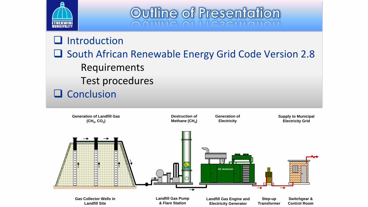
Introduction South African Renewable Energy Grid Code Version 2.8
Requirements Test procedures
Conclusion
Gas Collector Wells in
Landfill Site
Landfill Gas Pump
& Flare StationLandfill Gas Engine and
Electricity Generator
Step-up
Transformer
Switchgear &
Control Room
Generation of Landfill Gas
(CH4, CO2)
Destruction of
Methane (CH4)
Generation of
Electricity
Supply to Municipal
Electricity Grid
GE Jenbacher

It accordance to the Electricity Regulation Act (Act 4, 2006), it is mandatory forall Renewable Power Plants (RPP) connecting on the Eskom/Municipalitytransmission or distribution grid to comply with the requirements of the SouthAfrican Renewable Energy Grid Code (SAREGC).
However the requirements and testing methods of the SAREGC Version 2.8 isnot well understood by many.
This presentation willserve to discuss therequirements from theSAREGC Version 2.8and possible methodsto conduct grid codecompliance testing forRPP in South Africa.

Photovoltaic Plants
Concentrated Solar Power plants
Wind power plants
Small hydro power plants
Biomass power plants
Biogas power plants
Landfill gas power plants
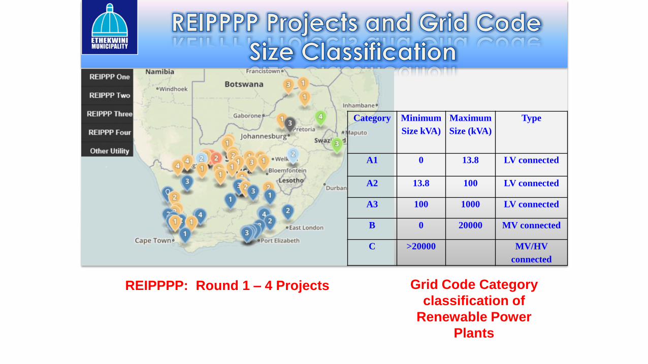
Category Minimum
Size kVA)
Maximum
Size (kVA)
Type
A1 0 13.8 LV connected
A2 13.8 100 LV connected
A3 100 1000 LV connected
B 0 20000 MV connected
C >20000 MV/HV
connected
Grid Code Category
classification of
Renewable Power
Plants
REIPPPP: Round 1 – 4 Projects

The RPP needs to
remain connected in
Area A, B and D
The RPP may
disconnect in Area C
The RPP must withstand
voltage drops to zero for
150 milliseconds
For voltages up to
120%, the RPP needs
to remain connected
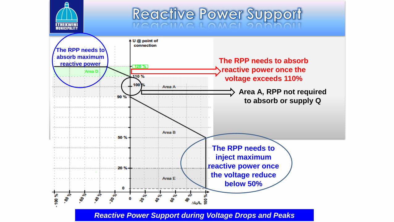
Reactive Power Support during Voltage Drops and Peaks
The RPP needs to absorb
reactive power once the
voltage exceeds 110%
Area A, RPP not required
to absorb or supply Q
The RPP needs to
absorb maximum
reactive power
The RPP needs to
inject maximum
reactive power once
the voltage reduce
below 50%

The RPP must withstand voltage drops to zero for
150 milliseconds
V = 0 Volts
Maximum Q
Minimum P
VRTC for Category B and RPP

Control Function Category B Category C
Frequency Control - ˣAbsolute Production Constraint ˣ ˣDelta Production Constraint - ˣPower Gradient Constraint ˣ ˣReactive Power (Q) Control ˣ ˣPower Factor Control ˣ ˣVoltage Control ˣ ˣ
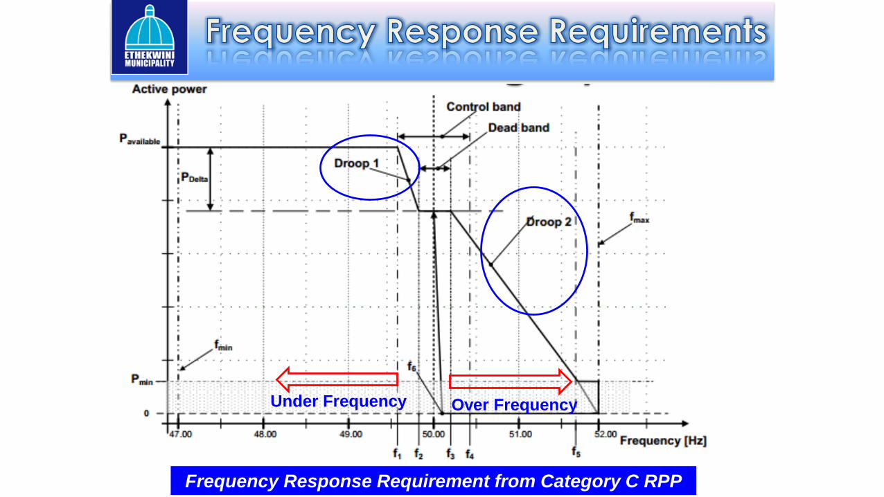
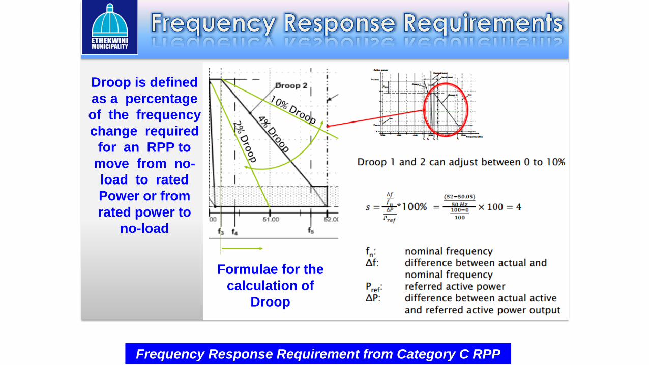
Frequency Response Requirement from Category C RPP
Over FrequencyUnder Frequency
Frequency Response Requirement from Category C RPP
Formulae for the
calculation of
Droop
Droop is defined
as a percentage
of the frequency
change required
for an RPP to
move from no-
load to rated
Power or from
rated power to
no-load
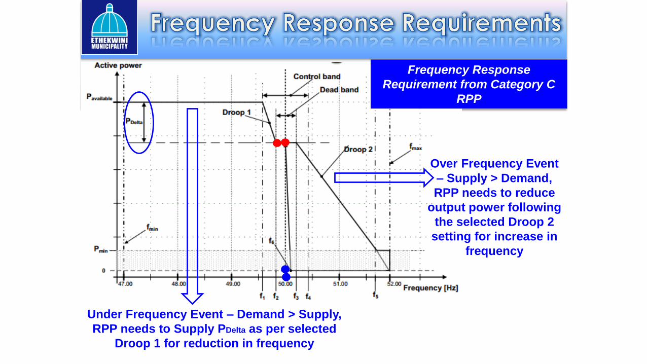
Frequency Response
Requirement from Category C
RPP
Over Frequency Event
– Supply > Demand,
RPP needs to reduce
output power following
the selected Droop 2
setting for increase in
frequency
Under Frequency Event – Demand > Supply,
RPP needs to Supply PDelta as per selected
Droop 1 for reduction in frequency

Grid Code Compliance Testing for Under Frequency Response
Plant supplying
PDelta in an under
frequency situation
Deactivation
of PDelta
49 Hz
48 Hz
49.5 Hz
50 Hz 49.85 Hz 50 HzSet Point 1
Set Point 2 Set Point 3
Set Point 4
Set Point 5
Enable PDelta
FREQ SET POINT 0: 50 Hz
f SET POINT 1: 49.85 Hz
f SET POINT 2: 49.5 Hz
f SET POINT 3: 49 Hz
f SET POINT 4: 48 Hz
f SET POINT 5: 50 Hz
Set Point 0

Reactive Power
Capability Testing at
PAvailable which is ≥
20% of PMax
QMax Cat B: Q/PN = 0.228
QMax Cat C: Q/PN = 0.33QMin Cat C: Q/PN = - 0.33
QMin Cat B: Q/PN = - 0.228

Reactive Power Capability
Testing at PAvailable and
P = 20% PMax
Un
UMax
UMin
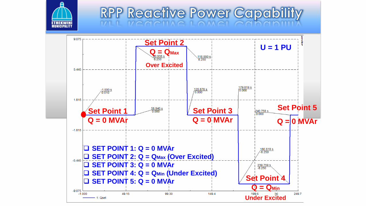
TEST @ U = 1 PU
Q SET POINT 1: 0 MVAr
Q SET POINT 2: QMAX
Q SET POINT 3: 0 MVAr
Q SET POINT 4: QMIN
Q SET POINT 5: 0 MVAr
TEST @ U = UMax
Q SET POINT 1: 0 MVAr
Q SET POINT 2: QMin
Q SET POINT 3: 0 MVAr
TEST @ U = UMin
Q SET POINT 1: 0 MVAr
Q SET POINT 2: QMax
Q SET POINT 3: 0 MVAr
Category B RPP
[-0.228 ≤(Q/PMax)≤0.228] at U = 1PU
Category C RPP
[-0.33 ≤(Q/PMax)≤0.33] at U = 1PU
Set Point 5
Q = 0 MVAr
Set Point 3
Q = 0 MVAr
Set Point 2
Q = QMax
Over Excited
Set Point 1
Q = 0 MVAr
Set Point 4
Q = QMin
Under Excited
U = 1 PU
SET POINT 1: Q = 0 MVAr
SET POINT 2: Q = QMax (Over Excited)
SET POINT 3: Q = 0 MVAr
SET POINT 4: Q = QMin (Under Excited)
SET POINT 5: Q = 0 MVAr

PF = 1 (Unity)
PF = 0.975 (Cat B)
or 0.95 (Cat A) PF = 0.975 (Cat B) or
0.95 (Cat C)Over excited - Leading
Under excited - Lagging
TEST @ P = PAvailable
& P = 20% PMax
PF SET POINT 1: UNITY
PF SET POINT 2: PF MAX
PF SET POINT 3: UNITY
PF SET POINT 4: PF MIN
PF SET POINT 5: UNITY
1 2345

Set Point 1
PF = Unity
Set Point 3
PF = Unity
Set Point 5
PF = Unity
Set Point 4
PF = -0.95
Under Excited
Set Point 2
PF = 0.95
Over Excited
Power Factor Control
Function Testing
Test at P = PAvailable and
P = 20% PMax
PF SET POINT 1: UNITY
PF SET POINT 2: 0.95
PF SET POINT 3: UNITY
PF SET POINT 4: -0.95
PF SET POINT 5: UNITY

Power
Gradient
Constraint
Power Gradient
Constraint
Delta Production
Constraint
Absolute
Production
Constraint

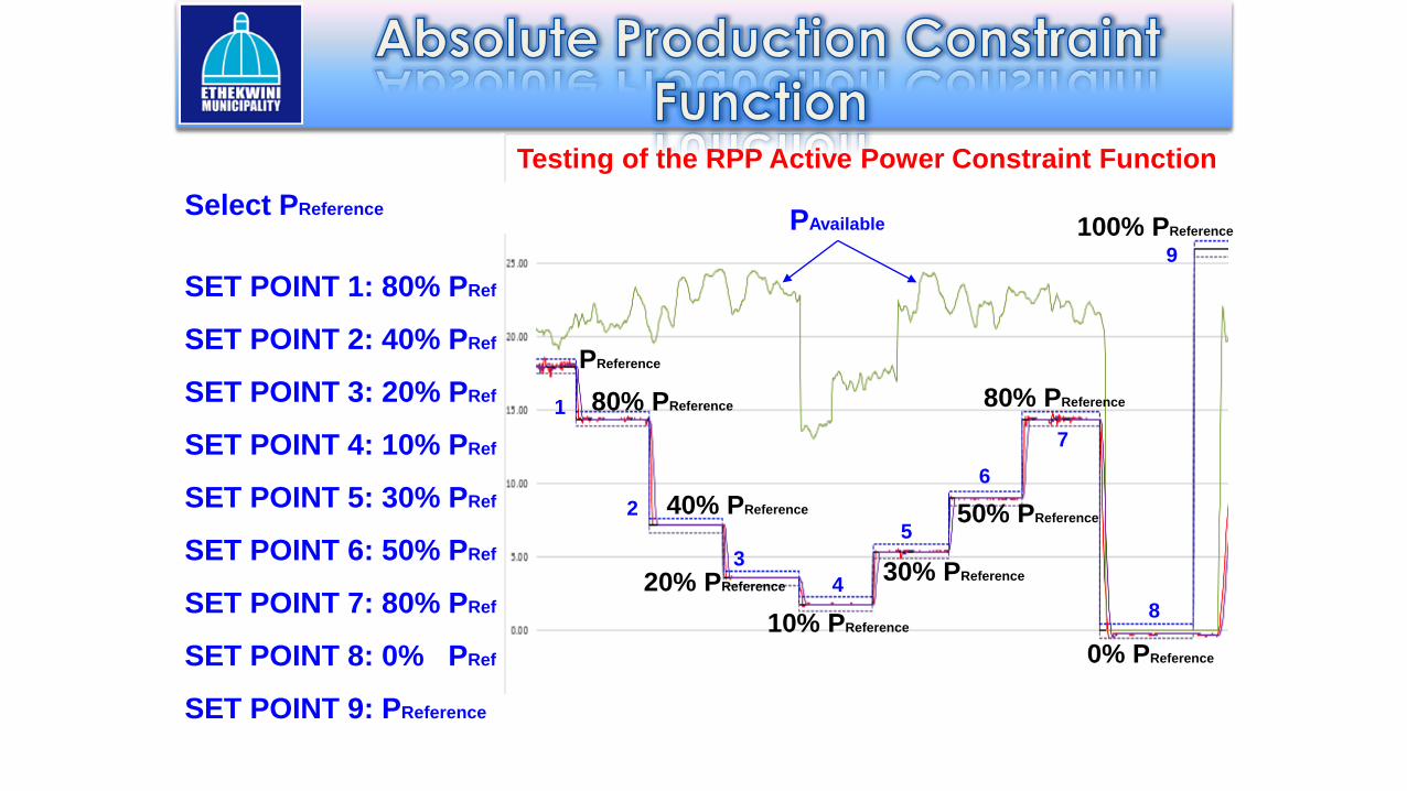
Absolute Production Constraint
An Absolute Production Constraint Function is used to constrain the
output active power from the RPP to a predefined power MW limit at
the POC.
This is typically used to protect the network against overloading.
Absolute
Production
Constraint
Available
Active
Power
PReference
80% PReference
40% PReference
20% PReference
10% PReference
30% PReference
50% PReference
80% PReference
0% PReference
1
2
3
4
5
6
7
8
Testing of the RPP Active Power Constraint Function
Select PReference
SET POINT 1: 80% PRef
SET POINT 2: 40% PRef
SET POINT 3: 20% PRef
SET POINT 4: 10% PRef
SET POINT 5: 30% PRef
SET POINT 6: 50% PRef
SET POINT 7: 80% PRef
SET POINT 8: 0% PRef
SET POINT 9: PReference
100% PReferencePAvailable
9

A Delta Production Constraint function is used to constrain the
active power from the RPP to a required constant value in
proportion to the possible active power.
It is typically used to establish a control reserve for frequency
control during under frequency conditions.
PDelta

0.00
5.00
10.00
15.00
20.00
25.00
30.00
02:2
1:57
PM
02:2
2:16
PM
02:2
2:35
PM
02:2
2:54
PM
02:2
3:13
PM
02:2
3:32
PM
02:2
3:51
PM
02:2
4:10
PM
02:2
4:29
PM
02:2
4:48
PM
02:2
5:07
PM
02:2
5:26
PM
02:2
5:45
PM
02:2
6:04
PM
02:2
6:23
PM
02:2
6:42
PM
02:2
7:01
PM
02:2
7:20
PM
02:2
7:39
PM
02:2
7:58
PM
02:2
8:17
PM
02:2
8:36
PM
02:2
8:55
PM
02:2
9:14
PM
02:2
9:33
PM
02:2
9:52
PM
02:3
0:11
PM
02:3
0:30
PM
02:3
0:49
PM
02:3
1:08
PM
02:3
1:27
PM
02:3
1:46
PM
02:3
2:05
PM
02:3
2:24
PM
02:3
2:43
PM
02:3
3:02
PM
Pow
er (M
W)
Wind Farm Test Results - Delta Production Constraint @ 10%
Actual Power (MW) Available active power
PDelta Setting (%) 10 second average
PDelta set at 10% PAvailable
Activate PDelta Deactivate PDelta
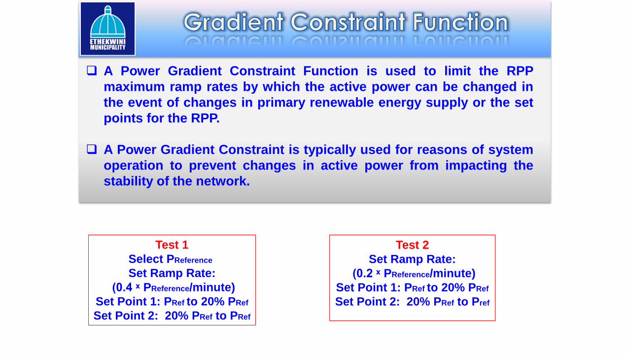
A Power Gradient Constraint Function is used to limit the RPP
maximum ramp rates by which the active power can be changed in
the event of changes in primary renewable energy supply or the set
points for the RPP.
A Power Gradient Constraint is typically used for reasons of system
operation to prevent changes in active power from impacting the
stability of the network.
Test 1
Select PReference
Set Ramp Rate:
(0.4 ˣ PReference/minute)
Set Point 1: PRef to 20% PRef
Set Point 2: 20% PRef to PRef
Test 2
Set Ramp Rate:
(0.2 ˣ PReference/minute)
Set Point 1: PRef to 20% PRef
Set Point 2: 20% PRef to Pref

PAvailable
PReference
20% of PReference
PReferencePReference
20% of PReference
Ramp Rate
0.4 × Preference/min
Ramp Rate
0.2 × Preference/min
2 Minutes 4 Minutes
Set Ramp Rate:
(0.4 ˣ PReference/minute)
Test 1: PRef to 20% PRef
Test 2: 20% PRef to PRef
Set Ramp Rate:
(0.2 ˣ PReference/minute)
Test 1: PRef to 20% PRef
Test 2: 20% PRef to PRef
2 Minutes4 Minutes
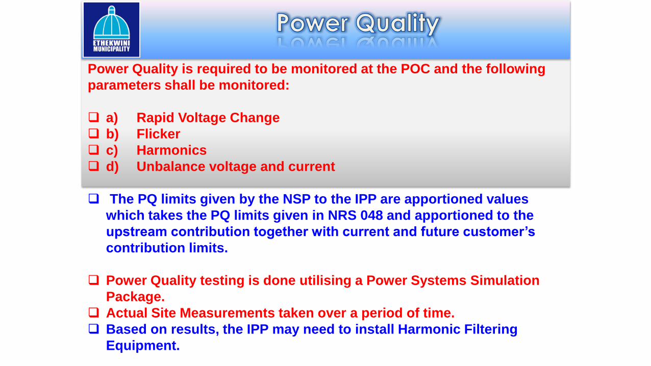
Power Quality is required to be monitored at the POC and the following
parameters shall be monitored:
a) Rapid Voltage Change
b) Flicker
c) Harmonics
d) Unbalance voltage and current
The PQ limits given by the NSP to the IPP are apportioned values
which takes the PQ limits given in NRS 048 and apportioned to the
upstream contribution together with current and future customer’s
contribution limits.
Power Quality testing is done utilising a Power Systems Simulation
Package.
Actual Site Measurements taken over a period of time.
Based on results, the IPP may need to install Harmonic Filtering
Equipment.
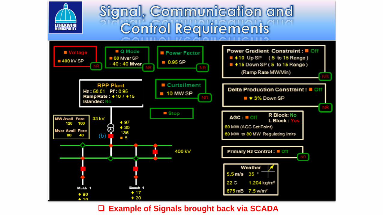
Example of Signals brought back via SCADA

There are many opportunities for renewable energy generation in
South Africa with supporting programs such as the REIPPPP.
Compliance to the South African Renewable Energy Grid Code is
mandatory and all RPPs must comply with the code at the point of
connection onto the utility grid
The SAREGC Version 2.8 is currently undergoing further changes to
include more detailed protection requirements, power quality
requirements and amendments to the requirements from certain
types of RPP technology.
This paper provides a simple introduction to utilities and developers
on the SAREGC requirements and provide some practical testing
methods that can be employed to prove grid code compliance of
RPPs.

Comments & Questions???


![AMEU newsletter - Oct 2019 · 2020. 8. 5. · AMEU NEWS November 2019 [2] The July 2019 meetings of the AMEU and SARPA KZN Branches took place on the 11th and 12th at the Riverside](https://img.pdfslide.us/doc/110x75/602ffb5c1edcf402f85adebf/ameu-newsletter-oct-2019-2020-8-5-ameu-news-november-2019-2-the-july-2019.jpg)