Embed Size (px)
Citation preview
© 2009, Renesas Technology America, Inc., All Rights Reserved1
Introduction
Purpose
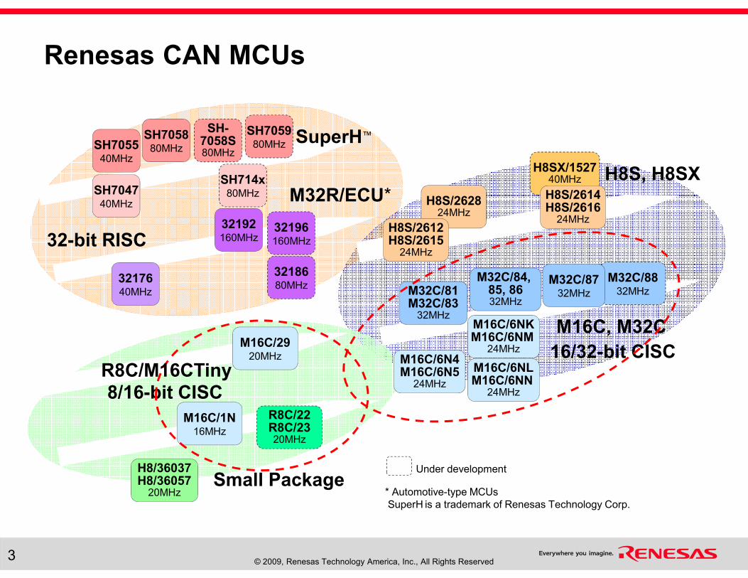
� This training course provides an overview of the Renesas microcontrollers (MCUs) that provide a CAN peripheral for building robust and economical networked, multi-processor embedded systems.
Objectives
� Learn about the range of MCUs that have CAN peripherals and how they fit into the wide range of devices that Renesas offers.
� Get details on M16C CAN MCUs, which are excellent choices for embedded system applications that apply CAN technology.
Content
� 22 pages
� 3 questions
Learning Time
� 35 minutes
© 2009, Renesas Technology America, Inc., All Rights Reserved2
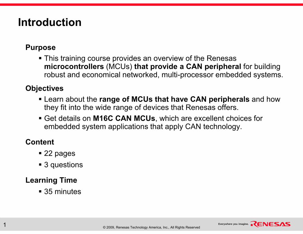
Why Use CAN Technology?
� Controller Area Network is an increasingly popular 2-wire
(twisted pair) serial-bus communication method that is:
� Reliable (delivering error-free communication)
� Economical (having low wiring and hardware costs)
� Scaleable (allowing easy expandability with low node-connection costs)
� Available (providing many MCU choices with off-the-shelf tool support)
� CAN is an ideal design choice for systems that require:
� Low cost
� High noise immunity
� Fast communication speeds
� Excellent flexibility for accommodating configuration changes
� Compliance to international standards
� A quick time-to-market
� A relatively long product life cycle and long-term support
© 2009, Renesas Technology America, Inc., All Rights Reserved3
SH705540MHz
SH705880MHz
SH704740MHz H8S/2628
24MHz
H8/36037H8/36057
20MHz
H8SX/152740MHz
M32C/81M32C/83
32MHz
M16C/1N16MHz
Small Package
M16C, M32C
H8S, H8SX
32-bit RISC
R8C/22R8C/2320MHz
SH705980MHz
16/32-bit CISC
8/16-bit CISC
M32R/ECU*
SuperH™
M16C/6N4M16C/6N5
24MHz
M16C/6NLM16C/6NN
24MHz
M16C/6NKM16C/6NM
24MHz
SH-7058S80MHz
SH714x80MHz
M32C/84, 85, 8632MHz
M32C/8832MHz
H8S/2614H8S/2616
24MHz
3218680MHz
32192160MHz
32196160MHz
3217640MHz
Under development
* Automotive-type MCUs
SuperH is a trademark of Renesas Technology Corp.
M32C/8732MHz
H8S/2612H8S/2615
24MHz
M16C/2920MHz
R8C/M16CTiny
Renesas CAN MCUs
© 2009, Renesas Technology America, Inc., All Rights Reserved4
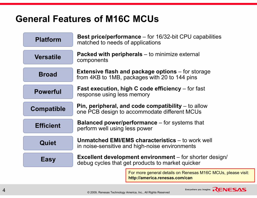
General Features of M16C MCUs
Best price/performance – for 16/32-bit CPU capabilities matched to needs of applicationsPlatform
Packed with peripherals – to minimize external components
Versatile
Extensive flash and package options – for storagefrom 4KB to 1MB, packages with 20 to 144 pins
Broad
Fast execution, high C code efficiency – for fast response using less memoryPowerful
Pin, peripheral, and code compatibility – to allow one PCB design to accommodate different MCUs Compatible
Balanced power/performance – for systems that perform well using less powerEfficient
Unmatched EMI/EMS characteristics – to work well in noise-sensitive and high-noise environments
Quiet
Excellent development environment – for shorter design/ debug cycles that get products to market quicker
Easy
For more general details on Renesas M16C MCUs, please visit:
http://america.renesas.com/can
© 2009, Renesas Technology America, Inc., All Rights Reserved5
R8C/10,1216MHz@3-5V
R8C/11,1320MHz@3-5V
R8C/14~/1720MHz@3-5V
M16C/2620MHz@3-5V
M16C/26A20MHz@3-5V
M16C/2820MHz@3-5V
M16C/1016MHz
M16C/22LCD
M16C/24USB 2.0
M16C/62A16MHz@5V
M16C/6VCCD, OSD
M16C/6HTeletext
M16C/6KKeyboard
M16C/6SPLC
M16C/62M10MHz@3V
M16C/62N16MHz@3V
M16C/62P24MHz@3-5V
M16C/3016MHz@5V
M16C/30L16MHz@3V
M16C/30P16MHz@5V
M32C/8032MHz
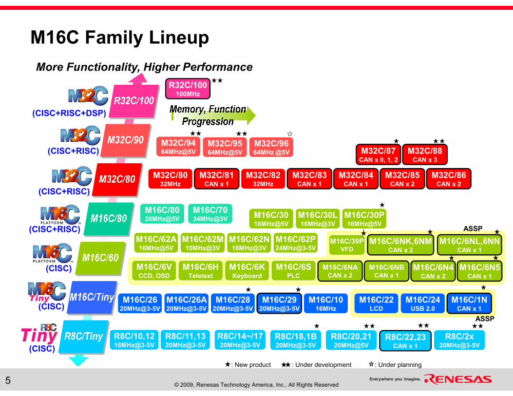
M32C/9464MHz@5V
M32C/8232MHz
M32C/9564MHz@5V
M32C/9664MHz @5V
R8C/18,1B20MHz@3-5V
R8C/20,2120MHz@5V
R8C/2x20MHz@3-5V
M16C/39PVFD
(CISC)
(CISC)
(CISC+RISC+DSP)
(CISC+RISC)
(CISC+RISC)
(CISC+RISC)
(CISC)
M16C/2920MHz@3-5V
M16C/1NCAN x 1
M16C/6NACAN x 2
M16C/6NBCAN x 1
M16C/6N4CAN x 2
M16C/6N5CAN x 1
ASSP
M32C/81CAN x 1
M32C/83CAN x 1
M32C/84CAN x 1
M32C/85CAN x 2
M32C/86CAN x 2
M32C/87CAN x 0, 1, 2
M32C/88CAN x 3
R32C/100100MHz
M16C/6NK,6NMCAN x 2
M16C/6NL,6NNCAN x 1
R8C/22,23CAN x 1
: New product : Under development : Under planning
ASSP
More Functionality, Higher Performance
M16C/6VCCD, OSD
M16C/6HTeletext
M16C/6KKeyboard
M16C/6SPLC
M16C/39PVFD
M16C/22LCD
M16C/24USB 2.0
M16C/8020MHz@5V
M16C/7034MHz@3V
M16C Family Lineup
© 2009, Renesas Technology America, Inc., All Rights Reserved6
R8C/10,1216MHz@3-5V
R8C/11,1320MHz@3-5V
R8C/14~/1720MHz@3-5V
M16C/2620MHz@3-5V
M16C/26A20MHz@3-5V
M16C/2820MHz@3-5V
M16C/1016MHz
M16C/22LCD
M16C/24USB 2.0
M16C/62A16MHz@5V
M16C/6VCCD, OSD
M16C/6HTeletext
M16C/6KKeyboard
M16C/6SPLC
M16C/62M10MHz@3V
M16C/62N16MHz@3V
M16C/62P24MHz@3-5V
M16C/3016MHz@5V
M16C/30L16MHz@3V
M16C/30P16MHz@5V
M32C/8032MHz
M32C/9464MHz@5V
M32C/8232MHz
M32C/9564MHz@5V
M32C/9664MHz @5V
R8C/18,1B20MHz@3-5V
R8C/20,2120MHz@5V
R8C/2x20MHz@3-5V
M16C/39PVFD
M16C/2920MHz@3-5V
M16C/1NCAN x 1
M16C/6NACAN x 2
M16C/6NBCAN x 1
M16C/6N4CAN x 2
M16C/6N5CAN x 1
ASSP
M32C/81CAN x 1
M32C/83CAN x 1
M32C/84CAN x 1
M32C/85CAN x 2
M32C/86CAN x 2
M32C/87CAN x 0, 1, 2
M32C/88CAN x 3
R32C/100100MHz
M16C/6NK,6NMCAN x 2
M16C/6NL,6NNCAN x 1
R8C/22,23CAN x 1
: New product : Under development : Under planning
ASSP
M16C/6VCCD, OSD
M16C/6HTeletext
M16C/6KKeyboard
M16C/6SPLC
M16C/39PVFD
M16C/22LCD
M16C/24USB 2.0
M16C/8020MHz@5V
M16C/7034MHz@3V
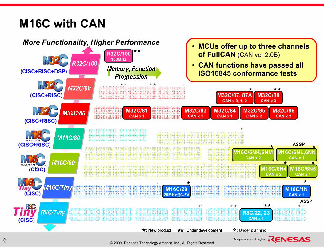
M16C with CAN
M16C/2920MHz@3-5V
M16C/1NCAN x 1
M16C/6N4CAN x 2
M16C/6N5CAN x 1
ASSP
M32C/81CAN x 1
M32C/83CAN x 1
M32C/84CAN x 1
M32C/85CAN x 2
M32C/86CAN x 2
M32C/87. 87ACAN x 0, 1, 2
M32C/88CAN x 3
R32C/100100MHz
M16C/6NK,6NMCAN x 2
M16C/6NL,6NNCAN x 1
R8C/22, 23CAN x 1
: New product : Under development
ASSP
More Functionality, Higher Performance• MCUs offer up to three channels
of FullCAN (CAN ver.2.0B)
• CAN functions have passed all ISO16845 conformance tests
(CISC)
(CISC)
(CISC+RISC)
(CISC+RISC)
(CISC+RISC)
(CISC)
(CISC+RISC+DSP)
© 2009, Renesas Technology America, Inc., All Rights Reserved7
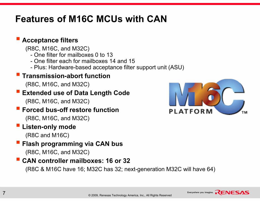
Features of M16C MCUs with CAN
� Acceptance filters
(R8C, M16C, and M32C)- One filter for mailboxes 0 to 13- One filter each for mailboxes 14 and 15- Plus: Hardware-based acceptance filter support unit (ASU)
� Transmission-abort function
(R8C, M16C, and M32C)
� Extended use of Data Length Code
(R8C, M16C, and M32C)
� Forced bus-off restore function
(R8C, M16C, and M32C)
� Listen-only mode
(R8C and M16C)
� Flash programming via CAN bus
(R8C, M16C, and M32C)
� CAN controller mailboxes: 16 or 32
(R8C & M16C have 16; M32C has 32; next-generation M32C will have 64)
© 2009, Renesas Technology America, Inc., All Rights Reserved8
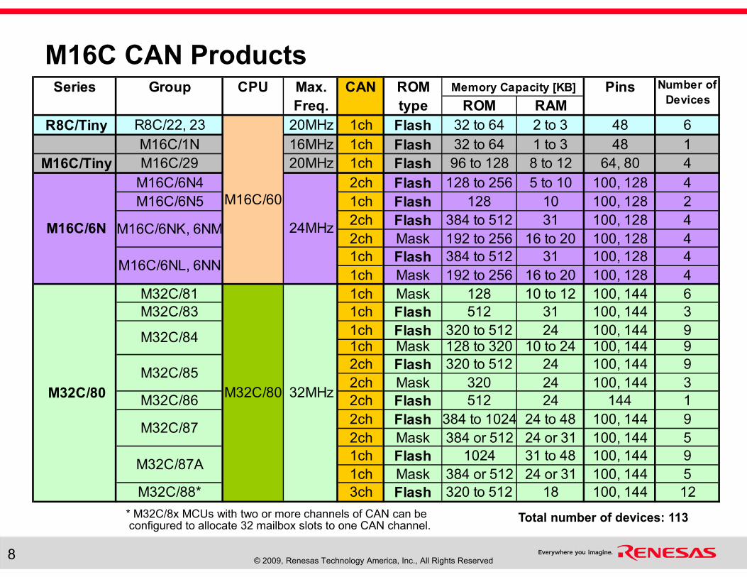
* M32C/8x MCUs with two or more channels of CAN can be configured to allocate 32 mailbox slots to one CAN channel.
Series Group CPU Max. CAN ROM Pins
Freq. type ROM RAM
R8C/Tiny R8C/22, 23 20MHz 1ch Flash 32 to 64 2 to 3 48 6
M16C/1N 16MHz 1ch Flash 32 to 64 1 to 3 48 1
M16C/Tiny M16C/29 20MHz 1ch Flash 96 to 128 8 to 12 64, 80 4
M16C/6N4 2ch Flash 128 to 256 5 to 10 100, 128 4
M16C/6N5 1ch Flash 128 10 100, 128 2
2ch Flash 384 to 512 31 100, 128 4
2ch Mask 192 to 256 16 to 20 100, 128 4
1ch Flash 384 to 512 31 100, 128 4
1ch Mask 192 to 256 16 to 20 100, 128 4
M32C/81 1ch Mask 128 10 to 12 100, 144 6
M32C/83 1ch Flash 512 31 100, 144 3
1ch Flash 320 to 512 24 100, 144 91ch Mask 128 to 320 10 to 24 100, 144 9
2ch Flash 320 to 512 24 100, 144 9
2ch Mask 320 24 100, 144 3
M32C/86 2ch Flash 512 24 144 1
2ch Flash 384 to 1024 24 to 48 100, 144 9
2ch Mask 384 or 512 24 or 31 100, 144 5
1ch Flash 1024 31 to 48 100, 144 9
1ch Mask 384 or 512 24 or 31 100, 144 5
M32C/88* 3ch Flash 320 to 512 18 100, 144 12
Number of
Devices
M16C/6N
M32C/87
M32C/80 M32C/80 32MHz
Memory Capacity [KB]
M32C/84
M32C/85
M32C/87A
M16C/6NK, 6NM
M16C/6NL, 6NN
M16C/60
24MHz
Total number of devices: 113
M16C CAN Products
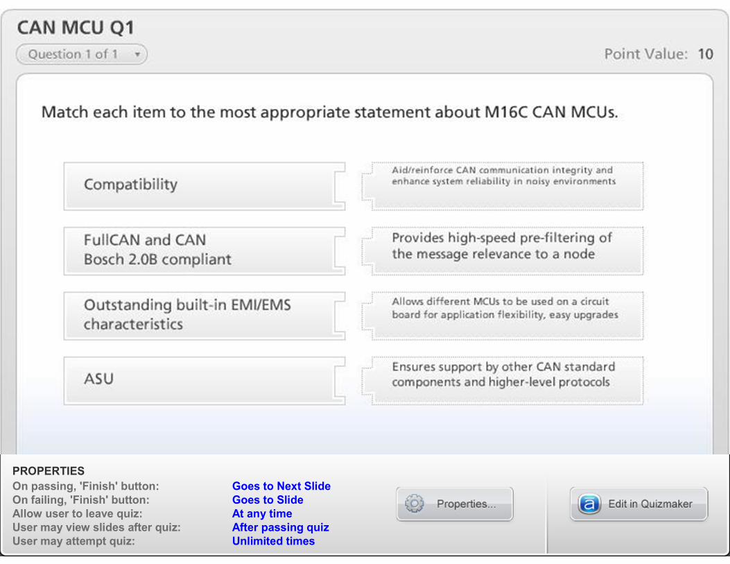
PROPERTIES
On passing, 'Finish' button: Goes to Next Slide
On failing, 'Finish' button: Goes to Slide
Allow user to leave quiz: At any time
User may view slides after quiz: After passing quiz
User may attempt quiz: Unlimited times
© 2009, Renesas Technology America, Inc., All Rights Reserved10
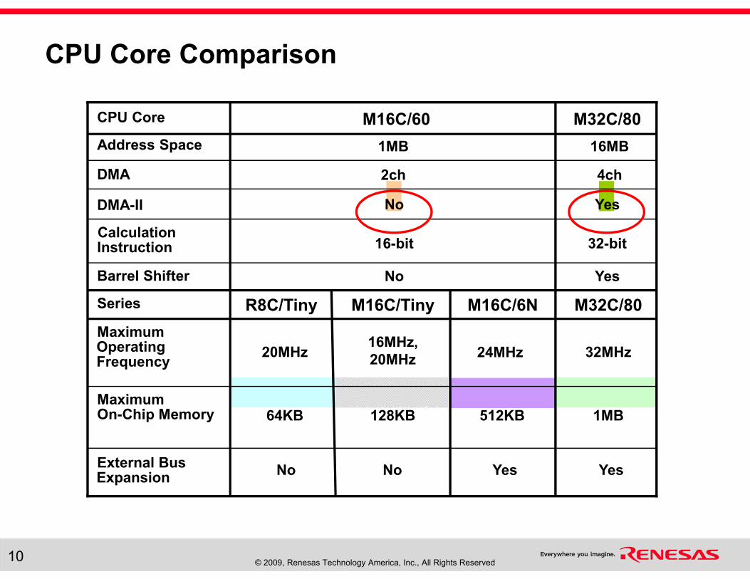
CPU Core Comparison
YesNoDMA-II
16MB1MBAddress Space
4ch2chDMA
32-bit16-bitCalculation Instruction
YesNoBarrel Shifter
M32C/80M16C/60CPU Core
512KB
24MHz
R8C/Tiny
128KB
16MHz,
20MHz
M16C/Tiny
32MHz20MHz
Maximum Operating Frequency
1MB64KBMaximum On-Chip Memory
YesExternal Bus Expansion
M32C/80M16C/6NSeries
YesNoNo
© 2009, Renesas Technology America, Inc., All Rights Reserved11
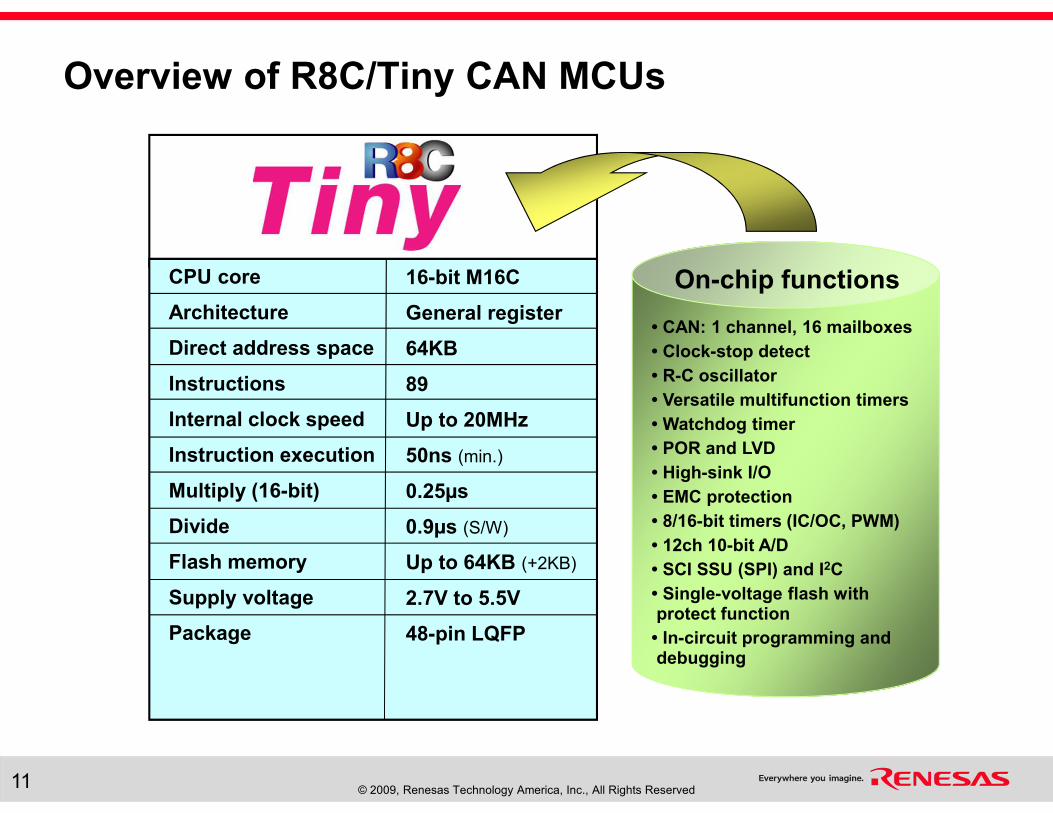
Overview of R8C/Tiny CAN MCUs
On-chip functions
• CAN: 1 channel, 16 mailboxes
• Clock-stop detect
• R-C oscillator
• Versatile multifunction timers
• Watchdog timer
• POR and LVD
• High-sink I/O
• EMC protection
• 8/16-bit timers (IC/OC, PWM)
• 12ch 10-bit A/D
• SCI SSU (SPI) and I2C
• Single-voltage flash with protect function
• In-circuit programming and debugging
CPU core
Architecture
Direct address space
Instructions
Internal clock speed
Instruction execution
Multiply (16-bit)
Divide
Flash memory
Supply voltage
Package
16-bit M16C
General register
64KB
89
Up to 20MHz
50ns (min.)
0.25µs
0.9µs (S/W)
Up to 64KB (+2KB)
2.7V to 5.5V
48-pin LQFP
© 2009, Renesas Technology America, Inc., All Rights Reserved12
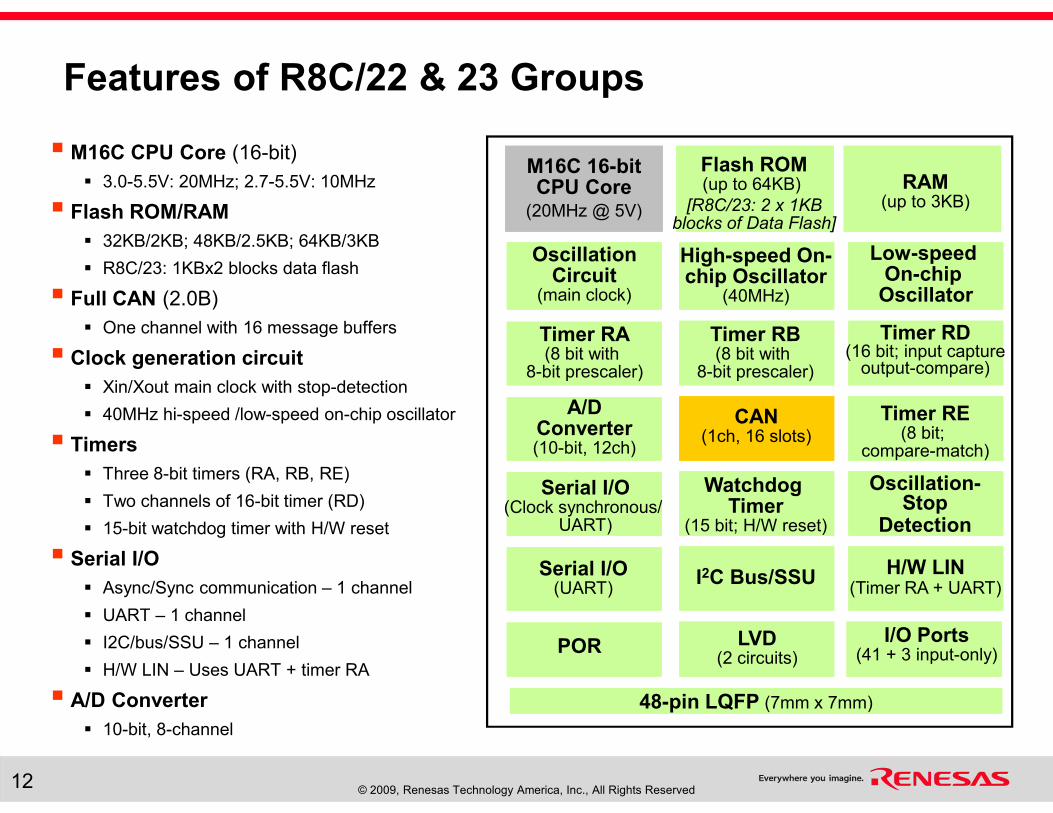
Features of R8C/22 & 23 Groups
� M16C CPU Core (16-bit)
� 3.0-5.5V: 20MHz; 2.7-5.5V: 10MHz
� Flash ROM/RAM
� 32KB/2KB; 48KB/2.5KB; 64KB/3KB
� R8C/23: 1KBx2 blocks data flash
� Full CAN (2.0B)
� One channel with 16 message buffers
� Clock generation circuit
� Xin/Xout main clock with stop-detection
� 40MHz hi-speed /low-speed on-chip oscillator
� Timers
� Three 8-bit timers (RA, RB, RE)
� Two channels of 16-bit timer (RD)
� 15-bit watchdog timer with H/W reset
� Serial I/O
� Async/Sync communication – 1 channel
� UART – 1 channel
� I2C/bus/SSU – 1 channel
� H/W LIN – Uses UART + timer RA
� A/D Converter
� 10-bit, 8-channel
M16C 16-bit CPU Core
(20MHz @ 5V)
48-pin LQFP (7mm x 7mm)
OscillationCircuit
(main clock)
High-speed On-chip Oscillator
(40MHz)
Low-speed On-chip
Oscillator
LVD(2 circuits)
Timer RA(8 bit with
8-bit prescaler)
Timer RD(16 bit; input capture
output-compare)
A/DConverter(10-bit, 12ch)
CAN(1ch, 16 slots)
Timer RE(8 bit;
compare-match)
Flash ROM(up to 64KB)
[R8C/23: 2 x 1KBblocks of Data Flash]
RAM(up to 3KB)
Timer RB(8 bit with
8-bit prescaler)
Oscillation-Stop
Detection
Watchdog Timer
(15 bit; H/W reset)
PORI/O Ports
(41 + 3 input-only)
Serial I/O(Clock synchronous/
UART)
I2C Bus/SSUSerial I/O(UART)
H/W LIN(Timer RA + UART)
© 2009, Renesas Technology America, Inc., All Rights Reserved13
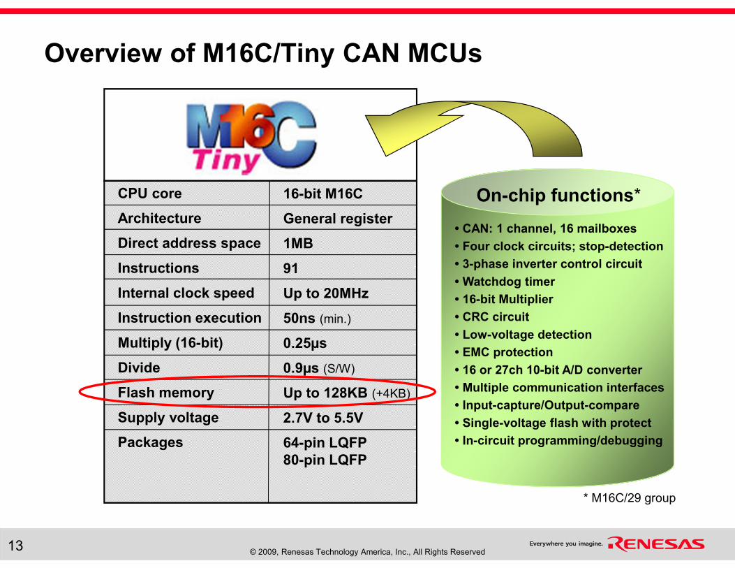
Overview of M16C/Tiny CAN MCUs
CPU core
Architecture
Direct address space
Instructions
Internal clock speed
Instruction execution
Multiply (16-bit)
Divide
Flash memory
Supply voltage
Packages
16-bit M16C
General register
1MB
91
Up to 20MHz
50ns (min.)
0.25µs
0.9µs (S/W)
Up to 128KB (+4KB)
2.7V to 5.5V
64-pin LQFP
80-pin LQFP
On-chip functions*
• CAN: 1 channel, 16 mailboxes
• Four clock circuits; stop-detection
• 3-phase inverter control circuit
• Watchdog timer
• 16-bit Multiplier
• CRC circuit
• Low-voltage detection
• EMC protection
• 16 or 27ch 10-bit A/D converter
• Multiple communication interfaces
• Input-capture/Output-compare
• Single-voltage flash with protect
• In-circuit programming/debugging
* M16C/29 group
© 2009, Renesas Technology America, Inc., All Rights Reserved14
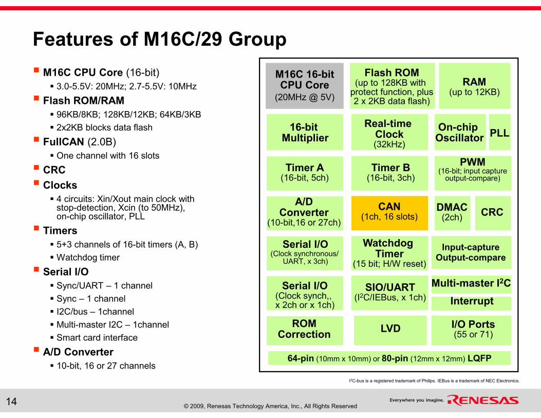
Features of M16C/29 Group
� M16C CPU Core (16-bit)
� 3.0-5.5V: 20MHz; 2.7-5.5V: 10MHz
� Flash ROM/RAM
� 96KB/8KB; 128KB/12KB; 64KB/3KB
� 2x2KB blocks data flash
� FullCAN (2.0B)
� One channel with 16 slots
� CRC
� Clocks
� 4 circuits: Xin/Xout main clock withstop-detection, Xcin (to 50MHz),on-chip oscillator, PLL
� Timers
� 5+3 channels of 16-bit timers (A, B)
� Watchdog timer
� Serial I/O
� Sync/UART – 1 channel
� Sync – 1 channel
� I2C/bus – 1channel
� Multi-master I2C – 1channel
� Smart card interface
� A/D Converter
� 10-bit, 16 or 27 channels
I2C-bus is a registered trademark of Philips. IEBus is a trademark of NEC Electronics.
M16C 16-bit CPU Core
(20MHz @ 5V)
64-pin (10mm x 10mm) or 80-pin (12mm x 12mm) LQFP
16-bit Multiplier
Timer A(16-bit, 5ch)
PWM(16-bit; input capture
output-compare)
A/DConverter
(10-bit,16 or 27ch)
CAN(1ch, 16 slots)
Flash ROM(up to 128KB with
protect function, plus 2 x 2KB data flash)
RAM(up to 12KB)
Watchdog Timer
(15 bit; H/W reset)
ROMCorrection
I/O Ports(55 or 71)
Serial I/O(Clock synchronous/
UART, x 3ch)
Serial I/O(Clock synch,, x 2ch or x 1ch)
Multi-master I2C
Timer B(16-bit, 3ch)
SIO/UART(I2C/IEBus, x 1ch)
DMAC(2ch)
Input-captureOutput-compare
LVD
CRC
Interrupt
On-chip Oscillator PLL
Real-time Clock(32kHz)
PROPERTIES
On passing, 'Finish' button: Goes to Next Slide
On failing, 'Finish' button: Goes to Slide
Allow user to leave quiz: At any time
User may view slides after quiz: After passing quiz
User may attempt quiz: Unlimited times
© 2009, Renesas Technology America, Inc., All Rights Reserved16
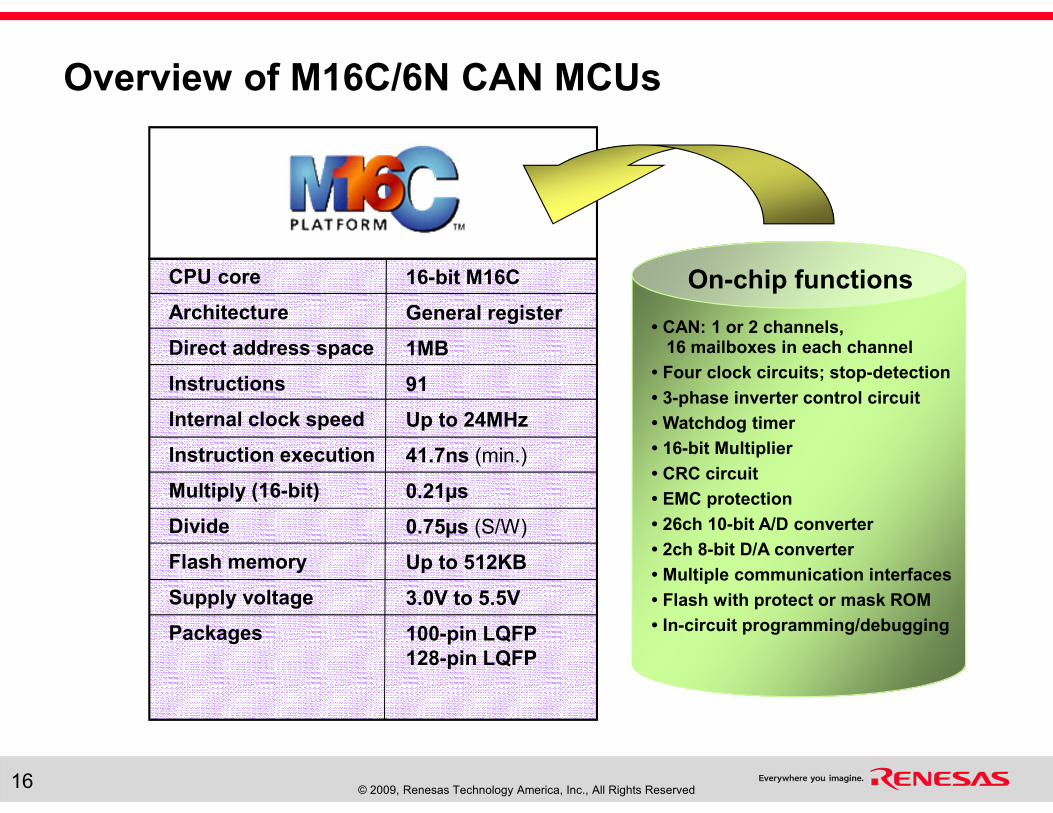
CPU core
Architecture
Direct address space
Instructions
Internal clock speed
Instruction execution
Multiply (16-bit)
Divide
Flash memory
Supply voltage
Packages
16-bit M16C
General register
1MB
91
Up to 24MHz
41.7ns (min.)
0.21µs
0.75µs (S/W)
Up to 512KB
3.0V to 5.5V
100-pin LQFP
128-pin LQFP
On-chip functions
• CAN: 1 or 2 channels, 16 mailboxes in each channel
• Four clock circuits; stop-detection
• 3-phase inverter control circuit
• Watchdog timer
• 16-bit Multiplier
• CRC circuit
• EMC protection
• 26ch 10-bit A/D converter
• 2ch 8-bit D/A converter
• Multiple communication interfaces
• Flash with protect or mask ROM
• In-circuit programming/debugging
Overview of M16C/6N CAN MCUs
© 2009, Renesas Technology America, Inc., All Rights Reserved17
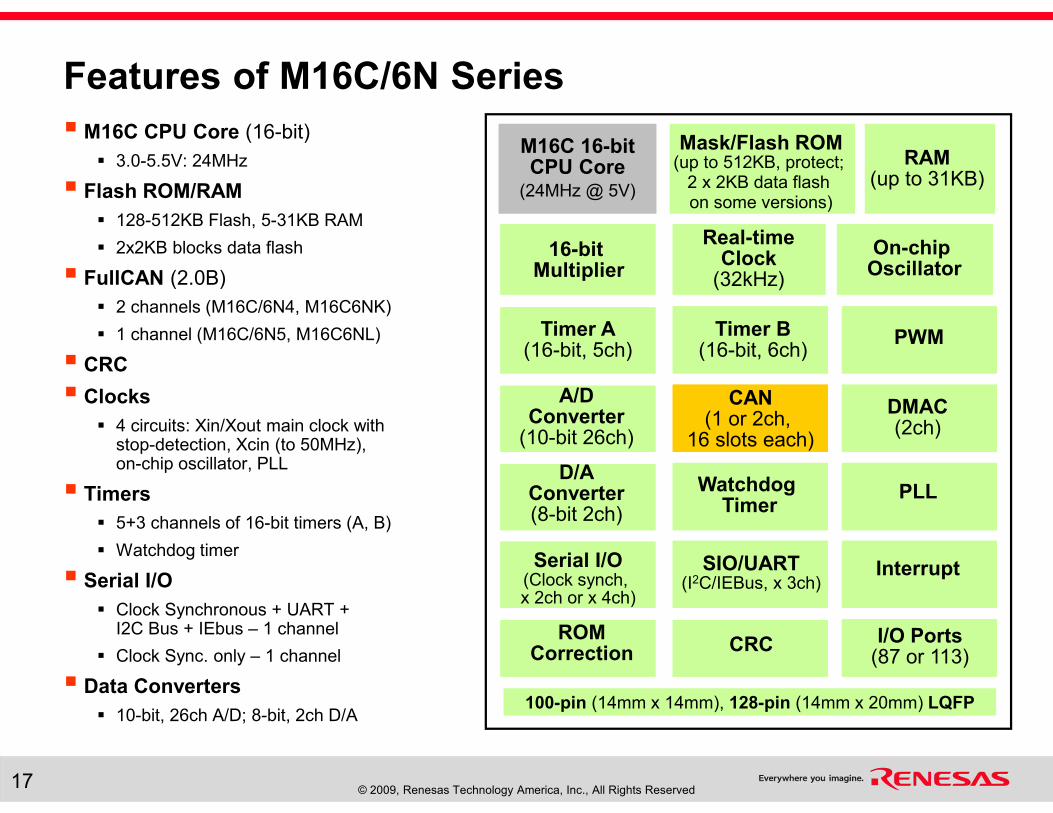
Features of M16C/6N Series
� M16C CPU Core (16-bit)
� 3.0-5.5V: 24MHz
� Flash ROM/RAM
� 128-512KB Flash, 5-31KB RAM
� 2x2KB blocks data flash
� FullCAN (2.0B)
� 2 channels (M16C/6N4, M16C6NK)
� 1 channel (M16C/6N5, M16C6NL)
� CRC
� Clocks
� 4 circuits: Xin/Xout main clock withstop-detection, Xcin (to 50MHz),on-chip oscillator, PLL
� Timers
� 5+3 channels of 16-bit timers (A, B)
� Watchdog timer
� Serial I/O
� Clock Synchronous + UART +I2C Bus + IEbus – 1 channel
� Clock Sync. only – 1 channel
� Data Converters
� 10-bit, 26ch A/D; 8-bit, 2ch D/A
M16C 16-bit CPU Core
(24MHz @ 5V)
100-pin (14mm x 14mm), 128-pin (14mm x 20mm) LQFP
16-bit Multiplier
Real-timeClock
(32kHz)
Timer A(16-bit, 5ch)
PWM
A/DConverter
(10-bit 26ch)
CAN(1 or 2ch,
16 slots each)
Mask/Flash ROM(up to 512KB, protect;
2 x 2KB data flash on some versions)
RAM(up to 31KB)
Watchdog Timer
ROMCorrection
I/O Ports(87 or 113)
Serial I/O(Clock synch, x 2ch or x 4ch)
Timer B(16-bit, 6ch)
SIO/UART(I2C/IEBus, x 3ch)
On-chip Oscillator
D/AConverter(8-bit 2ch)
PLL
Interrupt
CRC
DMAC(2ch)
© 2009, Renesas Technology America, Inc., All Rights Reserved18
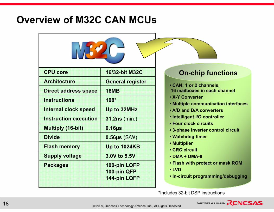
Overview of M32C CAN MCUs
CPU core
Architecture
Direct address space
Instructions
Internal clock speed
Instruction execution
Multiply (16-bit)
Divide
Flash memory
Supply voltage
Packages
16/32-bit M32C
General register
16MB
108*
Up to 32MHz
31.2ns (min.)
0.16µs
0.56µs (S/W)
Up to 1024KB
3.0V to 5.5V
100-pin LQFP
100-pin QFP
144-pin LQFP
On-chip functions
• CAN: 1 or 2 channels, 16 mailboxes in each channel
• X-Y Converter
• Multiple communication interfaces
• A/D and D/A converters
• Intelligent I/O controller
• Four clock circuits
• 3-phase inverter control circuit
• Watchdog timer
• Multiplier
• CRC circuit
• DMA + DMA-II
• Flash with protect or mask ROM
• LVD
• In-circuit programming/debugging
*Includes 32-bit DSP instructions
© 2009, Renesas Technology America, Inc., All Rights Reserved19
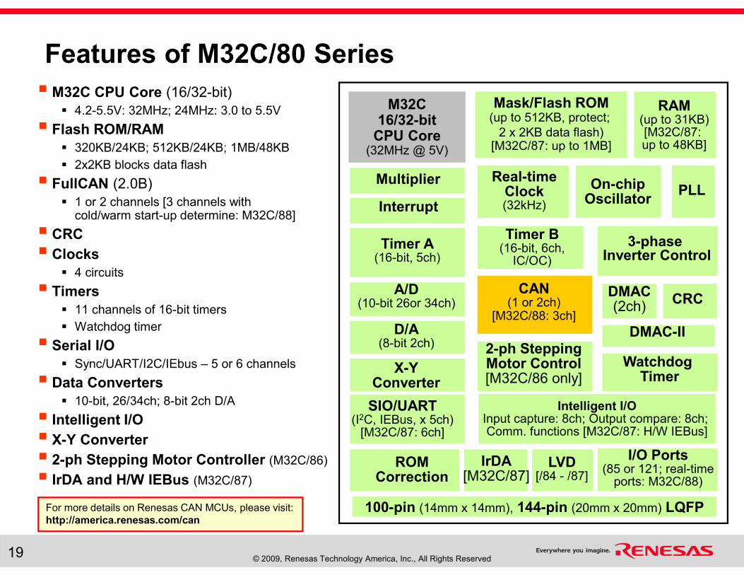
Features of M32C/80 Series
� M32C CPU Core (16/32-bit)
� 4.2-5.5V: 32MHz; 24MHz: 3.0 to 5.5V
� Flash ROM/RAM
� 320KB/24KB; 512KB/24KB; 1MB/48KB
� 2x2KB blocks data flash
� FullCAN (2.0B)
� 1 or 2 channels [3 channels withcold/warm start-up determine: M32C/88]
� CRC
� Clocks
� 4 circuits
� Timers
� 11 channels of 16-bit timers
� Watchdog timer
� Serial I/O
� Sync/UART/I2C/IEbus – 5 or 6 channels
� Data Converters
� 10-bit, 26/34ch; 8-bit 2ch D/A
� Intelligent I/O
� X-Y Converter
� 2-ph Stepping Motor Controller (M32C/86)
� IrDA and H/W IEBus (M32C/87)
M32C 16/32-bit
CPU Core(32MHz @ 5V)
100-pin (14mm x 14mm), 144-pin (20mm x 20mm) LQFP
Multiplier Real-timeClock(32kHz)
Timer A(16-bit, 5ch)
3-phase Inverter Control
A/D(10-bit 26or 34ch)
CAN(1 or 2ch)
[M32C/88: 3ch]
Mask/Flash ROM(up to 512KB, protect;
2 x 2KB data flash)[M32C/87: up to 1MB]
RAM(up to 31KB)[M32C/87: up to 48KB]
Watchdog Timer
ROMCorrection
I/O Ports(85 or 121; real-time
ports: M32C/88)
Timer B(16-bit, 6ch,
IC/OC)
SIO/UART(I2C, IEBus, x 5ch)
[M32C/87: 6ch]
On-chip Oscillator
D/A(8-bit 2ch)
IrDA[M32C/87]
DMAC(2ch)
PLLInterrupt
DMAC-II
Intelligent I/OInput capture: 8ch; Output compare: 8ch; Comm. functions [M32C/87: H/W IEBus]
LVD[/84 - /87]
CRC
2-ph SteppingMotor Control[M32C/86 only]
X-YConverter
For more details on Renesas CAN MCUs, please visit:
http://america.renesas.com/can
© 2009, Renesas Technology America, Inc., All Rights Reserved20
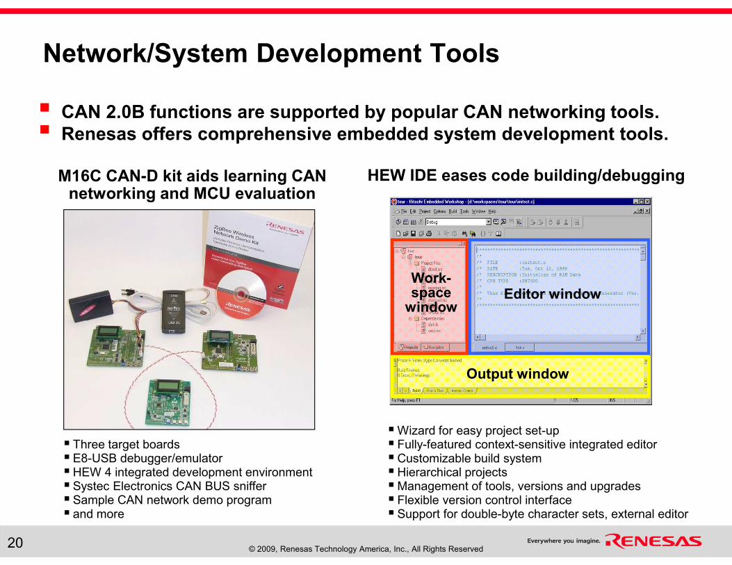
Network/System Development Tools
M16C CAN-D kit aids learning CAN networking and MCU evaluation
Editor windowWork-space
window
Output window
�Wizard for easy project set-up� Fully-featured context-sensitive integrated editor�Customizable build system�Hierarchical projects�Management of tools, versions and upgrades� Flexible version control interface� Support for double-byte character sets, external editor
� CAN 2.0B functions are supported by popular CAN networking tools.
� Renesas offers comprehensive embedded system development tools.
HEW IDE eases code building/debugging
� Three target boards� E8-USB debugger/emulator�HEW 4 integrated development environment� Systec Electronics CAN BUS sniffer� Sample CAN network demo program� and more
PROPERTIES
On passing, 'Finish' button: Goes to Next Slide
On failing, 'Finish' button: Goes to Slide
Allow user to leave quiz: At any time
User may view slides after quiz: After passing quiz
User may attempt quiz: Unlimited times
© 2009, Renesas Technology America, Inc., All Rights Reserved22
Course Summary
� CAN technology
� Renesas MCU product lines
� Renesas CAN MCUs
� R8C/Tiny, M16C/Tiny, M16C/6N, M32C/80 CAN MCUs
� Development tools