Embed Size (px)
Citation preview

Web: www.robokits.co.in Email: [email protected]
Page 1
Introduction
Raspberry Pi kit includes RGB Led module, different sensors like Touch sensor, Ultrasonic
sensor, Flame sensor, Temperature and humidity sensor and many more. It also includes LCD,
Bread Board and connecting wires, potentiometer, resistors, Buttons and also other components
which can useful for learning raspberry pi projects.
WiringPi
WiringPi is a PIN based GPIO access library written in C for the BCM2835 used in the
Raspberry Pi. It’s released under the GNU LGPLv3 license and is usable from C, C++ and RTB
(BASIC) as well as many other languages with suitable wrappers. It’s designed to be familiar to
people who have used the Arduino “wiring” system.

Web: www.robokits.co.in Email: [email protected]
Page 2
Table of Contents
Introduction .............................................................................................................................................. 1
WiringPi ..................................................................................................................................................... 1
Operation Demo ....................................................................................................................................... 3
Lesson 1 LED Blink ................................................................................................................................... 10
Lesson 2 Push Button .............................................................................................................................. 12
Lesson 3 Ball Switch ................................................................................................................................ 15
Lesson 4 Buzzer ....................................................................................................................................... 18
Lesson 5 Relay Module ........................................................................................................................... 21
Lesson 6 RGB LED .................................................................................................................................... 23
Lesson 7 1 digit 7 Segment Displays ....................................................................................................... 26
Lesson 8 4 Digit 7 segment display ......................................................................................................... 29
Lesson 9 Heart shaped display experiment ............................................................................................ 32
Lesson 10 9G Servo ................................................................................................................................. 36
Lesson 11 Stepper Motor ........................................................................................................................ 38
Lesson 12 Ultrasonic sensor .................................................................................................................... 41
Lesson 13 Touch sensor .......................................................................................................................... 44
Lesson 14 PCF8591 Module .................................................................................................................... 47
Lesson 15 Flame sensor .......................................................................................................................... 50
Lesson 16 Photoresistance Sensor .......................................................................................................... 53
Lesson 17 Thermistor sensor .................................................................................................................. 56
Lesson 18 Potentiometer ........................................................................................................................ 59
Lesson 19 Water level sensor ................................................................................................................. 62
Lesson 20 Joystick experiment ................................................................................................................ 65
Lesson 21 IR remote control experiment ............................................................................................... 68
Lesson 22 DHT11 Sensor experiment ..................................................................................................... 72
Lesson 23 Serial LCD................................................................................................................................ 75
Web: www.robokits.co.in Email: [email protected]
Page 3
Operation Demo
Step 1: Download and install WiringPi?
Most of the Rapbian versions are already preloaded with WiringPi. And the test methods are as
follows.
Open terminal and run: gpio –v
If you get something then it is already preloaded else you have to install it.
Refer following link if not installed,
http://wiringpi.com/download-and-install/
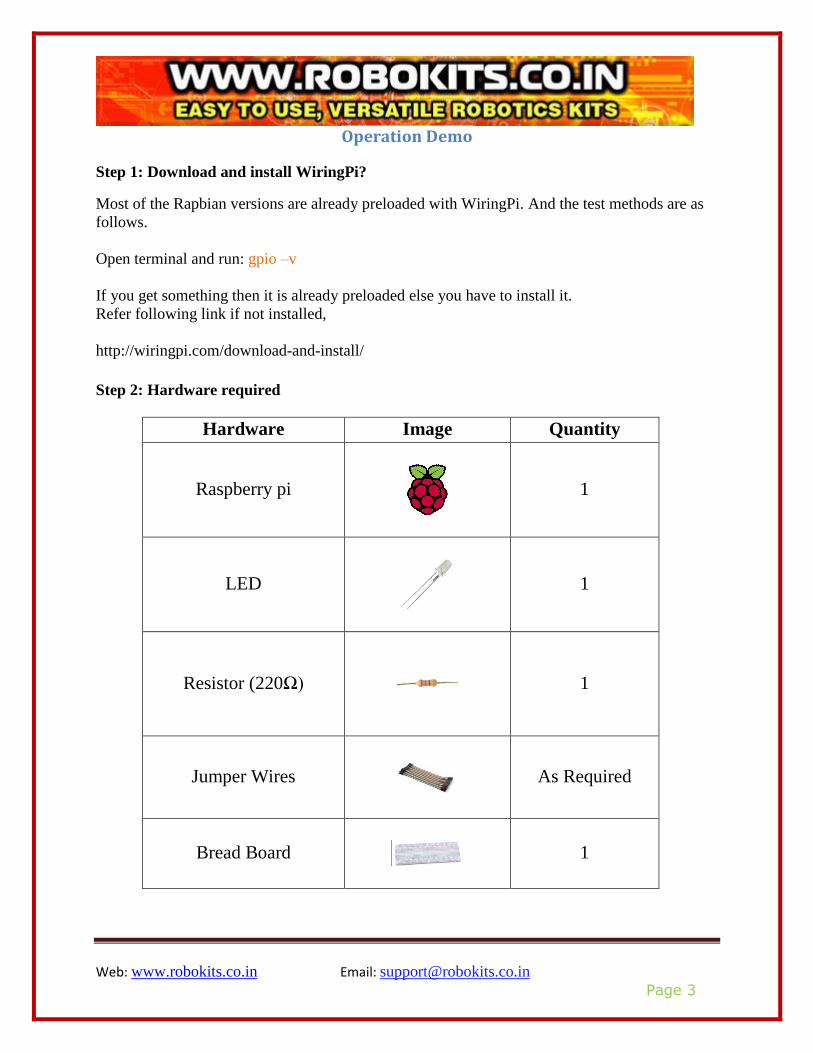
Step 2: Hardware required
Hardware Image Quantity
Raspberry pi
1
LED
1
Resistor (220Ω)
1
Jumper Wires
As Required
Bread Board
1
Web: www.robokits.co.in Email: [email protected]
Page 4
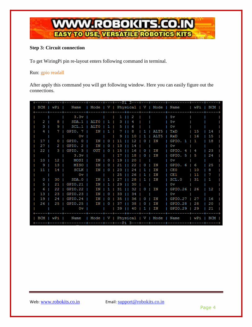
Step 3: Circuit connection
To get WiringPi pin re-layout enters following command in terminal.
Run: gpio readall After apply this command you will get following window. Here you can easily figure out the
connections.
Web: www.robokits.co.in Email: [email protected]
Page 5
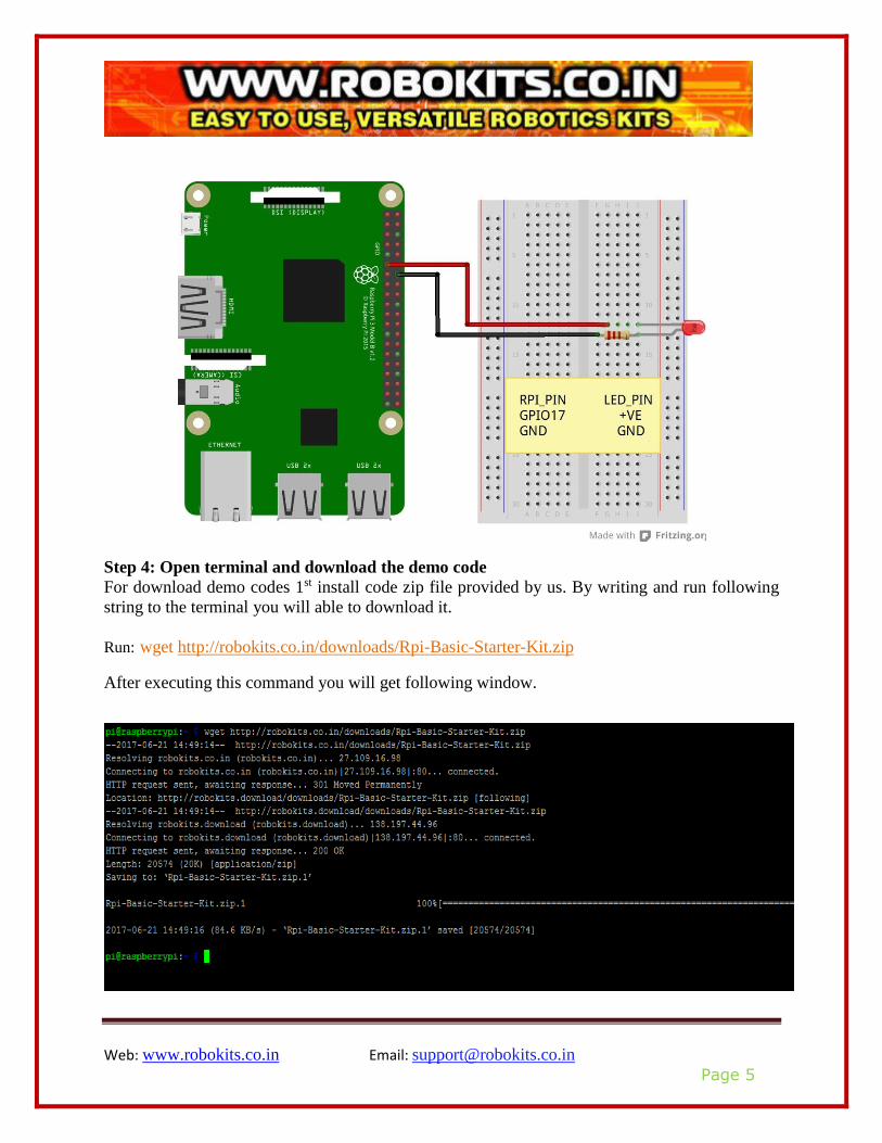
Step 4: Open terminal and download the demo code
For download demo codes 1st install code zip file provided by us. By writing and run following
string to the terminal you will able to download it.
Run: wget http://robokits.co.in/downloads/Rpi-Basic-Starter-Kit.zip
After executing this command you will get following window.
Web: www.robokits.co.in Email: [email protected]
Page 6
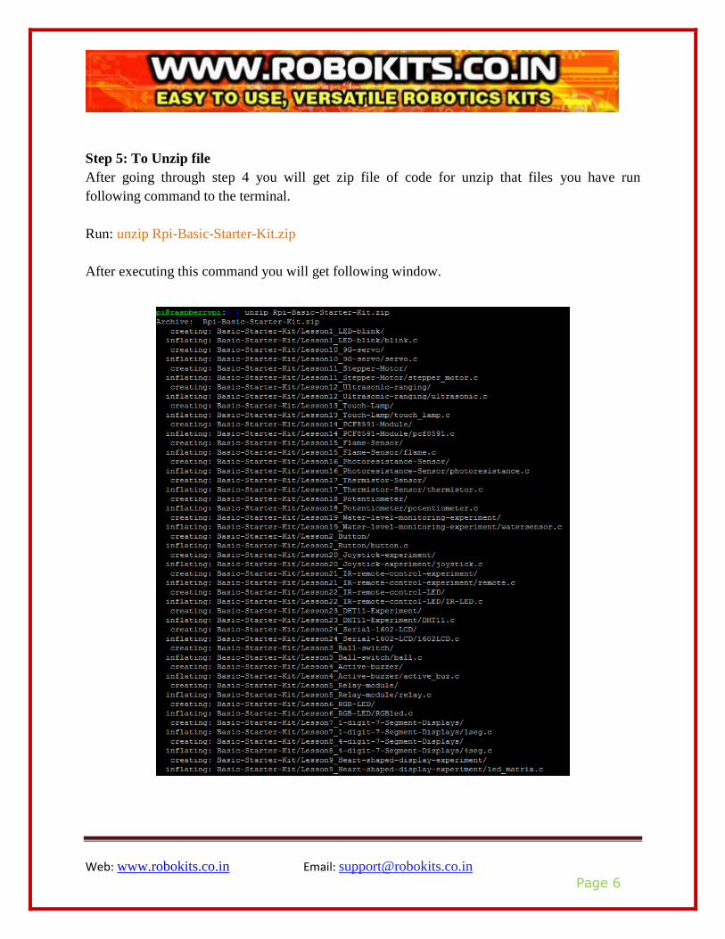
Step 5: To Unzip file
After going through step 4 you will get zip file of code for unzip that files you have run
following command to the terminal.
Run: unzip Rpi-Basic-Starter-Kit.zip
After executing this command you will get following window.
Web: www.robokits.co.in Email: [email protected]
Page 7
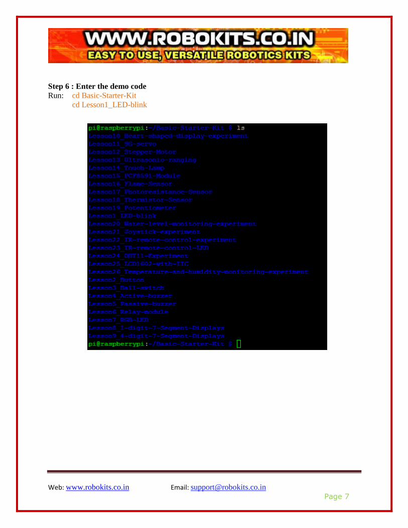
Step 6 : Enter the demo code
Run: cd Basic-Starter-Kit
cd Lesson1_LED-blink
Web: www.robokits.co.in Email: [email protected]
Page 8
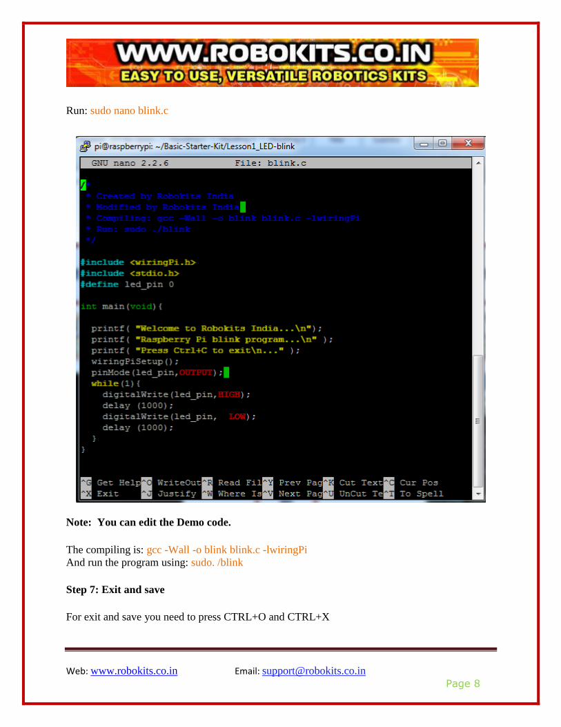
Run: sudo nano blink.c
Note: You can edit the Demo code.
The compiling is: gcc -Wall -o blink blink.c -lwiringPi
And run the program using: sudo. /blink
Step 7: Exit and save
For exit and save you need to press CTRL+O and CTRL+X

Web: www.robokits.co.in Email: [email protected]
Page 9
Step 8: Compiling
Run: gcc -Wall -o blink blink.c –lwiringPi
Note: if you want to compile “xxx.c” and you need run it by following this way. Run: gcc -Wall -o xxx xxx.c -lwiringPi
Or: g++ -Wall -o xxx xxx.c -lwiringPi
Step 9: Run the program
Run: sudo ./blink
Note: Exit the Program -> “Ctrl+c”.
Step 9: Application effect:
Blinks LED every 1 Second.
Web: www.robokits.co.in Email: [email protected]
Page 10
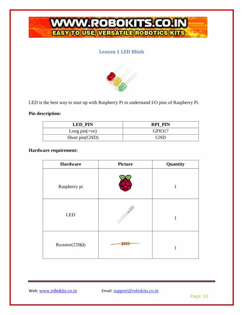
Lesson 1 LED Blink
LED is the best way to start up with Raspberry Pi to understand I/O pins of Raspberry Pi.
Pin description:
LED_PIN RPI_PIN
Long pin(+ve) GPIO17
Short pin(GND) GND
Hardware requirement:
Hardware Picture Quantity
Raspberry pi
1
LED
1
Resistor(220Ω)
1
Web: www.robokits.co.in Email: [email protected]
Page 11
Jumper Wires
As required
Bread Board
1
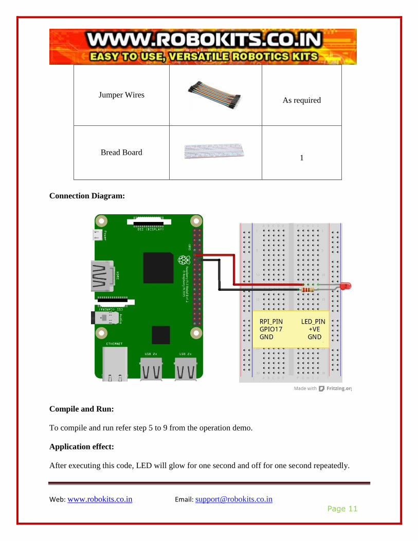
Connection Diagram:
Compile and Run:
To compile and run refer step 5 to 9 from the operation demo.
Application effect:
After executing this code, LED will glow for one second and off for one second repeatedly.
Web: www.robokits.co.in Email: [email protected]
Page 12
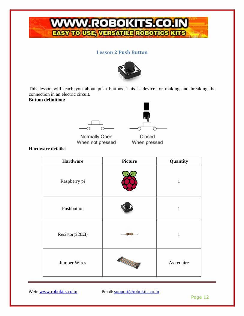
Lesson 2 Push Button
This lesson will teach you about push buttons. This is device for making and breaking the
connection in an electric circuit.
Button definition:
Hardware details:
Hardware Picture Quantity
Raspberry pi
1
Pushbutton
1
Resistor(220Ω)
1
Jumper Wires
As require
Web: www.robokits.co.in Email: [email protected]
Page 13
Bread Board
1
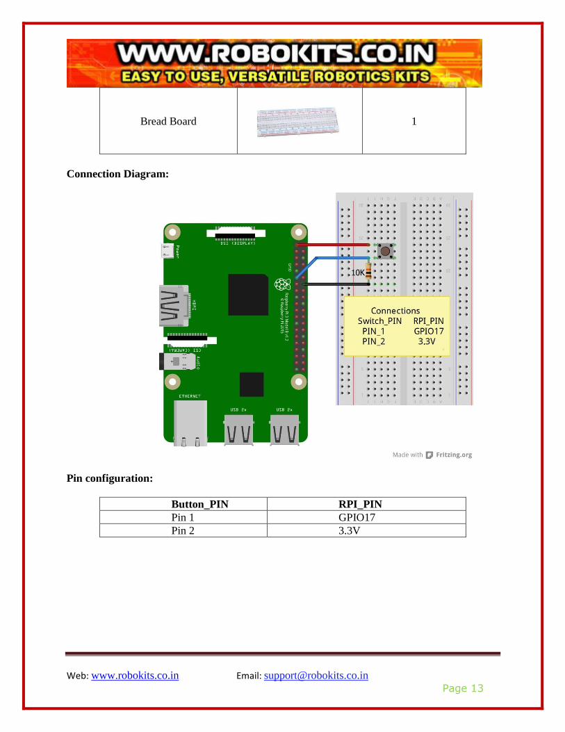
Connection Diagram:
Pin configuration:
Button_PIN RPI_PIN
Pin 1 GPIO17
Pin 2 3.3V

Web: www.robokits.co.in Email: [email protected]
Page 14
Compile and run:
For compile and run follow step 5 to step 9 from operation demo.
Application effect:
By executing this program and pressing push button you will find button state on the screen.
Web: www.robokits.co.in Email: [email protected]
Page 15
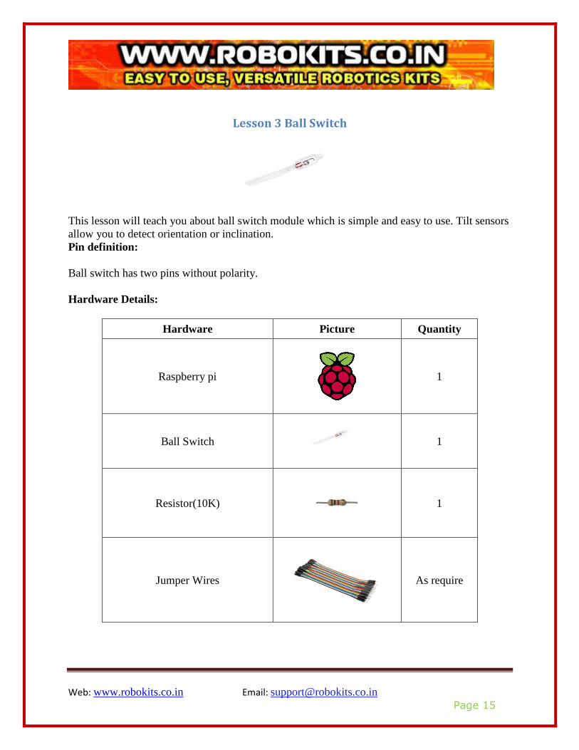
Lesson 3 Ball Switch
This lesson will teach you about ball switch module which is simple and easy to use. Tilt sensors
allow you to detect orientation or inclination. Pin definition:
Ball switch has two pins without polarity.
Hardware Details:
Hardware Picture Quantity
Raspberry pi
1
Ball Switch
1
Resistor(10K)
1
Jumper Wires
As require
Web: www.robokits.co.in Email: [email protected]
Page 16
Bread Board
1
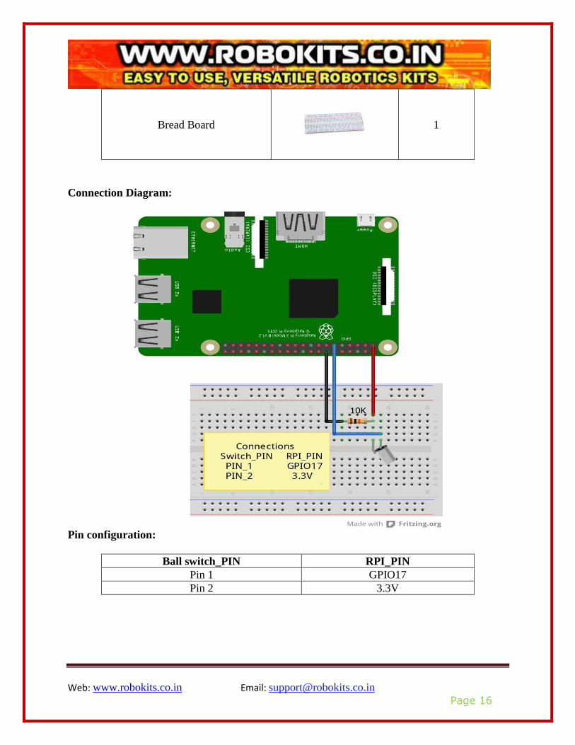
Connection Diagram:
Pin configuration:
Ball switch_PIN RPI_PIN
Pin 1 GPIO17
Pin 2 3.3V

Web: www.robokits.co.in Email: [email protected]
Page 17
Compile and run:
For compile and run follow step 5 to step 9 from operation demo.
Application effect:
By executing program and shocking the ball switch screen will display state of ball switch.
Web: www.robokits.co.in Email: [email protected]
Page 18
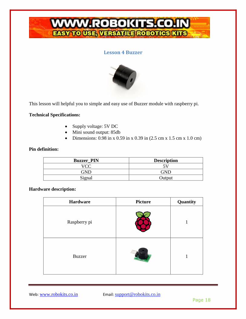
Lesson 4 Buzzer
This lesson will helpful you to simple and easy use of Buzzer module with raspberry pi.
Technical Specifications:
• Supply voltage: 5V DC
• Mini sound output: 85db
• Dimensions: 0.98 in x 0.59 in x 0.39 in (2.5 cm x 1.5 cm x 1.0 cm)
Pin definition:
Buzzer_PIN Description
VCC 5V
GND GND
Signal Output
Hardware description:
Hardware Picture Quantity
Raspberry pi
1
Buzzer
1
Web: www.robokits.co.in Email: [email protected]
Page 19
Jumper Wires
As require
Bread Board
1
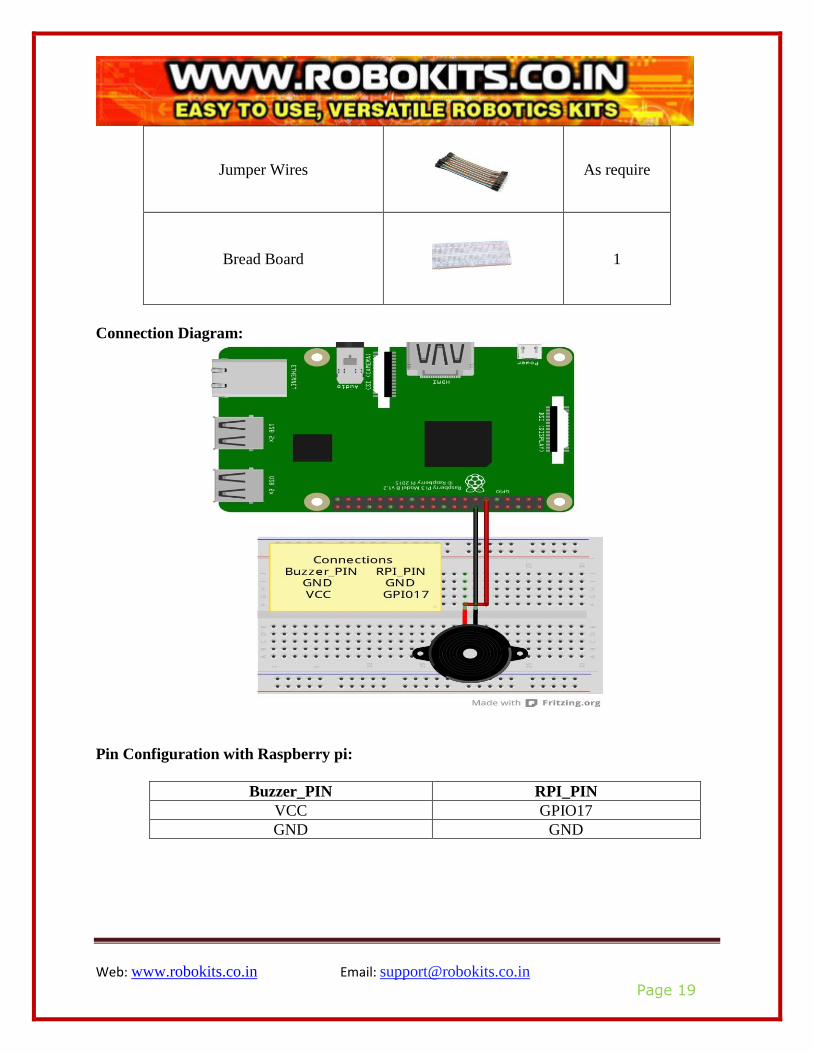
Connection Diagram:
Pin Configuration with Raspberry pi:
Buzzer_PIN RPI_PIN
VCC GPIO17
GND GND

Web: www.robokits.co.in Email: [email protected]
Page 20
Compile and run:
For compile and run follow step 5 to step 9 from operation demo.
Application effect:
After executing code you will find that buzzer is ringing

Web: www.robokits.co.in Email: [email protected]
Page 21
Lesson 5 Relay Module
This lesson will help to understand about relay module and how it is simple and easy to use.
Relay is electrically operated device.
Technical specifications:
It has three pins
Relay_PIN Description
VCC 5V
GND GND
Signal Input
Hardware details:
Hardware Picture Quantity
Raspberry pi
1
Relay Board
1
Jumper Wires
As require

Web: www.robokits.co.in Email: [email protected]
Page 22
Bread Board
1
Connection diagram:
Pin Configuration with Raspberry pi:
Relay_PIN RPI_PIN
VCC 5V
GND GND
S GPIO17
Compile and run:
For compile and run follow step 5 to step 9 from operation demo.
Application effect:
After executing code, according to the screen tips control relay.
Web: www.robokits.co.in Email: [email protected]
Page 23
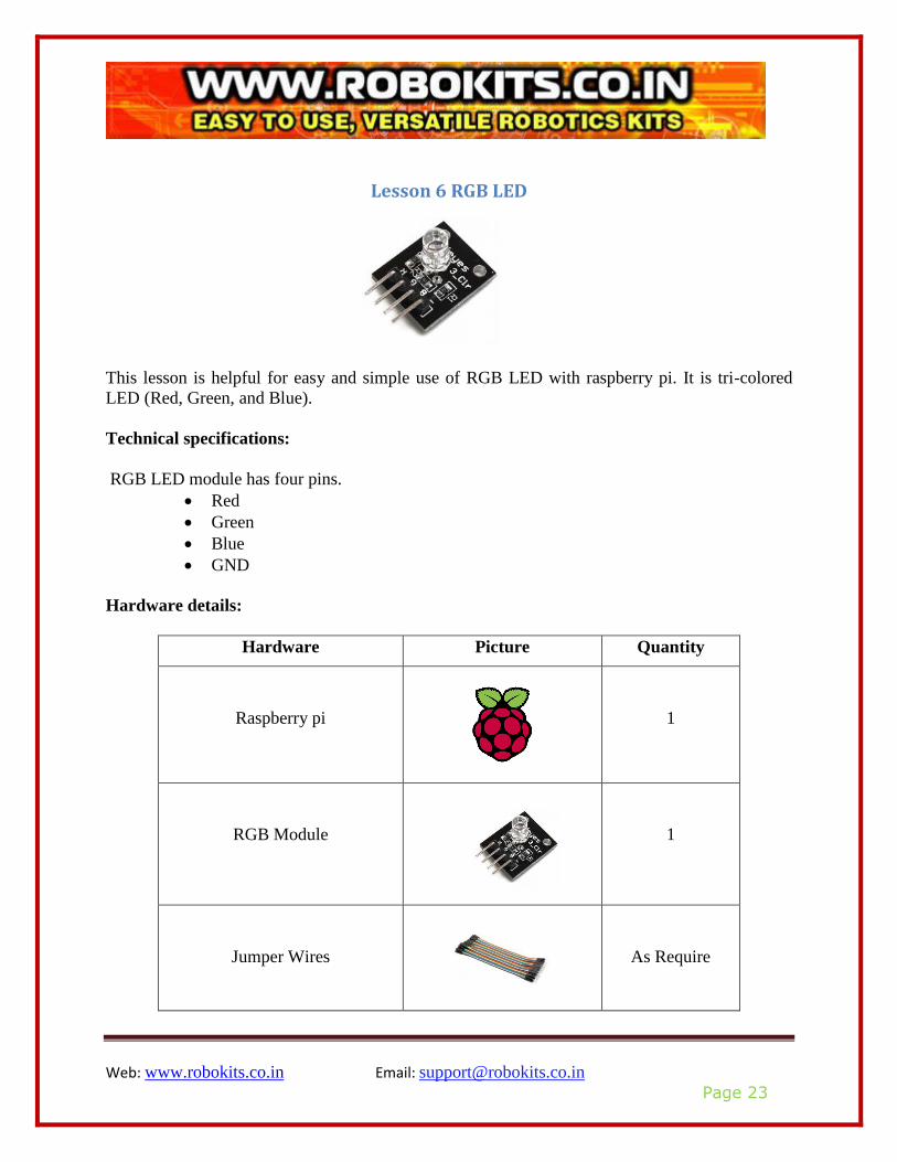
Lesson 6 RGB LED
This lesson is helpful for easy and simple use of RGB LED with raspberry pi. It is tri-colored
LED (Red, Green, and Blue).
Technical specifications:
RGB LED module has four pins.
• Red
• Green
• Blue
• GND
Hardware details:
Hardware Picture Quantity
Raspberry pi
1
RGB Module
1
Jumper Wires
As Require

Web: www.robokits.co.in Email: [email protected]
Page 24
Bread Board
1
Pin Configuration with Raspberry pi:
Module_PIN RPI_PIN
Red GPIO17
GND GND
Blue GPIO22
Green GPIO27
Connection diagram:

Web: www.robokits.co.in Email: [email protected]
Page 25
Compile and run:
For compile and run follow step 5 to step 9 from operation demo.
Application effect:
After executing code you will find that led emits six different colors.
Web: www.robokits.co.in Email: [email protected]
Page 26
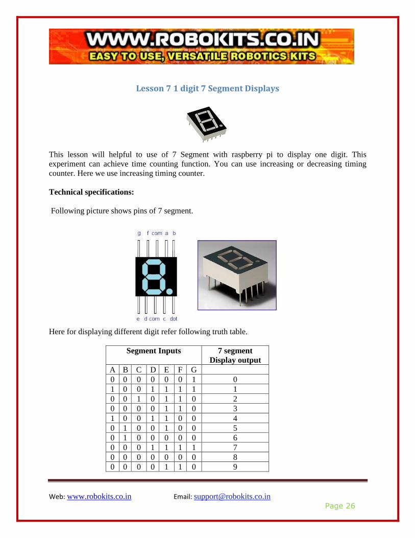
Lesson 7 1 digit 7 Segment Displays
This lesson will helpful to use of 7 Segment with raspberry pi to display one digit. This
experiment can achieve time counting function. You can use increasing or decreasing timing
counter. Here we use increasing timing counter.
Technical specifications:
Following picture shows pins of 7 segment.
Here for displaying different digit refer following truth table.
Segment Inputs 7 segment
Display output
A B C D E F G
0 0 0 0 0 0 1 0
1 0 0 1 1 1 1 1
0 0 1 0 1 1 0 2
0 0 0 0 1 1 0 3
1 0 0 1 1 0 0 4
0 1 0 0 1 0 0 5
0 1 0 0 0 0 0 6
0 0 0 1 1 1 1 7
0 0 0 0 0 0 0 8
0 0 0 0 1 1 0 9
Web: www.robokits.co.in Email: [email protected]
Page 27
Hardware requirement:
Hardware Picture Quantity
Raspberry pi
1
7 Segment
1
Jumper Wires
As Require
Resistor(220Ω)
8
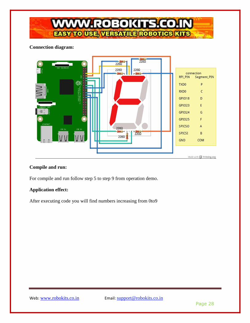
Pin Configuration with Raspberry pi:
7 segment_Pin RPI_PIN
P TXD0
C RXD0
D GPIO18
E GPIO23
G GPIO24
F GPIO25
A SPICSO
B SPICSI
COM GND
Web: www.robokits.co.in Email: [email protected]
Page 28
Connection diagram:
Compile and run:
For compile and run follow step 5 to step 9 from operation demo.
Application effect:
After executing code you will find numbers increasing from 0to9
Web: www.robokits.co.in Email: [email protected]
Page 29
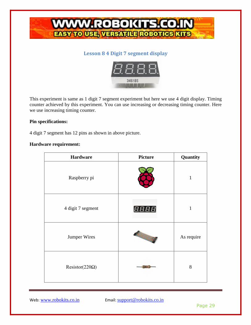
Lesson 8 4 Digit 7 segment display
This experiment is same as 1 digit 7 segment experiment but here we use 4 digit display. Timing
counter achieved by this experiment. You can use increasing or decreasing timing counter. Here
we use increasing timing counter.
Pin specifications:
4 digit 7 segment has 12 pins as shown in above picture.
Hardware requirement:
Hardware Picture Quantity
Raspberry pi
1
4 digit 7 segment
1
Jumper Wires
As require
Resistor(220Ω)
8
Web: www.robokits.co.in Email: [email protected]
Page 30
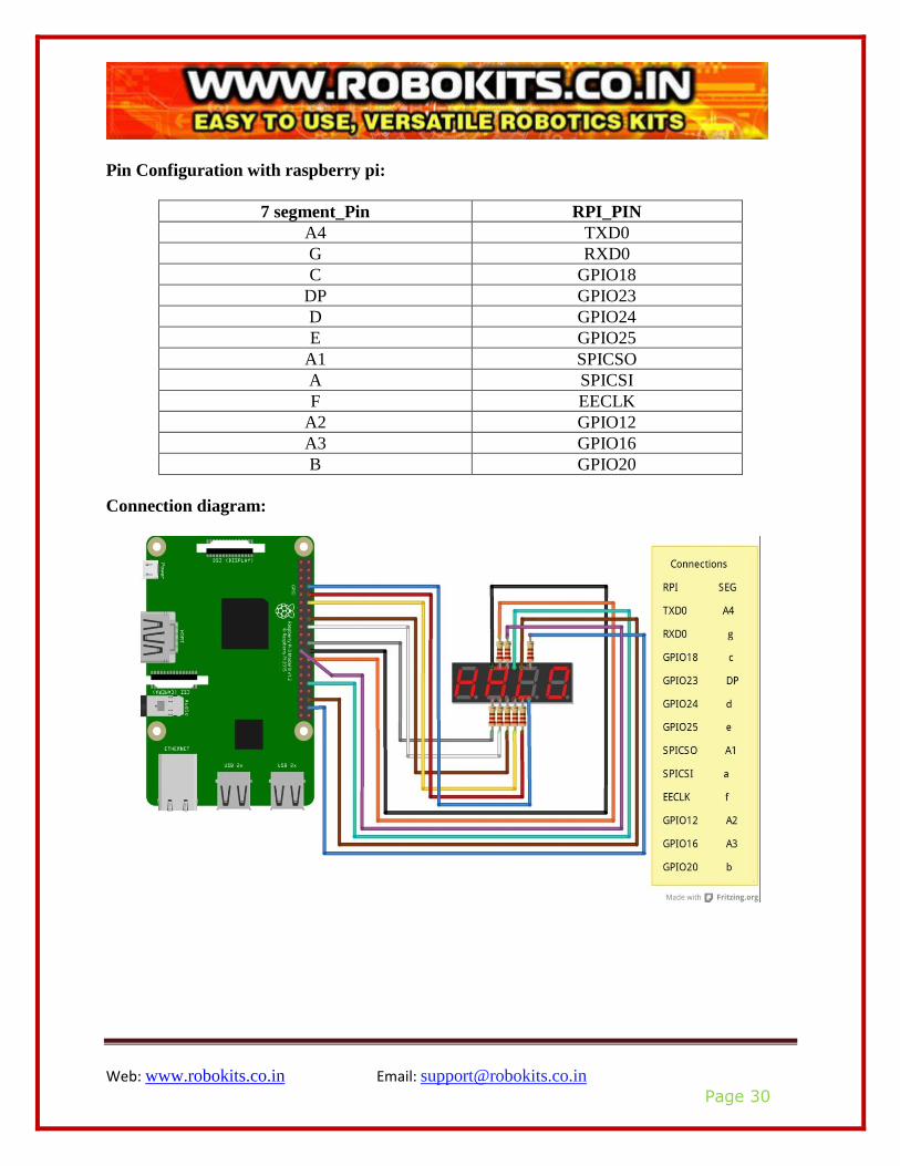
Pin Configuration with raspberry pi:
7 segment_Pin RPI_PIN
A4 TXD0
G RXD0
C GPIO18
DP GPIO23
D GPIO24
E GPIO25
A1 SPICSO
A SPICSI
F EECLK
A2 GPIO12
A3 GPIO16
B GPIO20
Connection diagram:
Web: www.robokits.co.in Email: [email protected]
Page 31
Compile and run:
For compile and run follow step 5 to step 9 from operation demo.
Application effect:
After executing code you will find numbers on display increases.
Web: www.robokits.co.in Email: [email protected]
Page 32
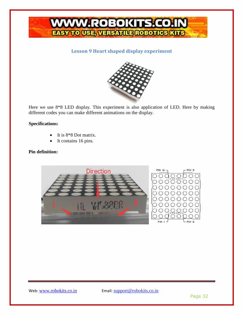
Lesson 9 Heart shaped display experiment
Here we use 8*8 LED display. This experiment is also application of LED. Here by making
different codes you can make different animations on the display.
Specifications:
• It is 8*8 Dot matrix.
• It contains 16 pins.
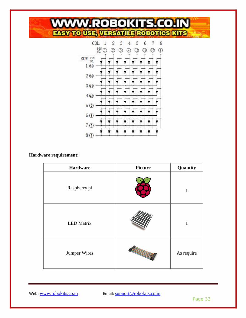
Pin definition:
Web: www.robokits.co.in Email: [email protected]
Page 33
Hardware requirement:
Hardware Picture Quantity
Raspberry pi
1
LED Matrix
1
Jumper Wires
As require
Web: www.robokits.co.in Email: [email protected]
Page 34
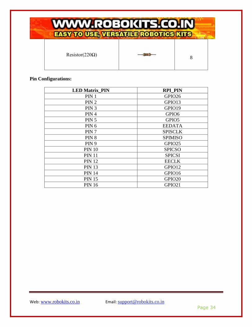
Resistor(220Ω)
8
Pin Configurations:
LED Matrix_PIN RPI_PIN
PIN 1 GPIO26
PIN 2 GPIO13
PIN 3 GPIO19
PIN 4 GPIO6
PIN 5 GPIO5
PIN 6 EEDATA
PIN 7 SPISCLK
PIN 8 SPIMISO
PIN 9 GPIO25
PIN 10 SPICSO
PIN 11 SPICSI
PIN 12 EECLK
PIN 13 GPIO12
PIN 14 GPIO16
PIN 15 GPIO20
PIN 16 GPIO21

Web: www.robokits.co.in Email: [email protected]
Page 35
Connection diagram:
Compile and run:
For compile and run follow step 5 to step 9 from operation demo.
Application effect:
After executing code you will see heart animation.
Further implementation:
By developing new codes you can make different animations with LED matrix. You can also use
LED matrix of different size.
Web: www.robokits.co.in Email: [email protected]
Page 36
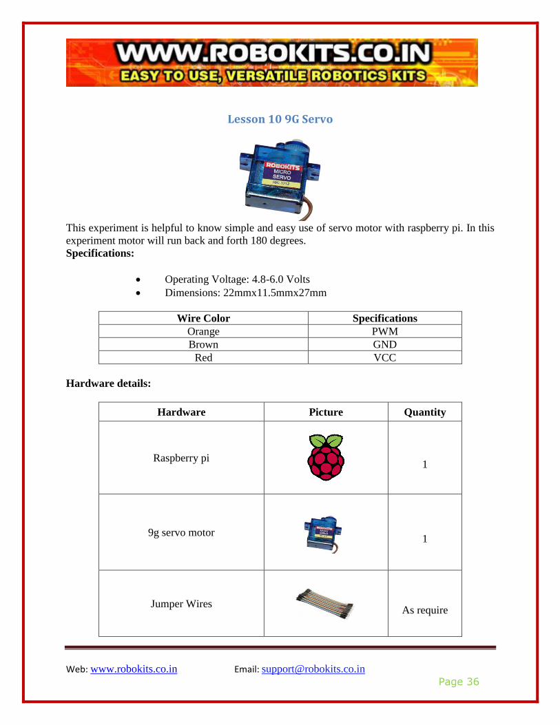
Lesson 10 9G Servo
This experiment is helpful to know simple and easy use of servo motor with raspberry pi. In this
experiment motor will run back and forth 180 degrees.
Specifications:
• Operating Voltage: 4.8-6.0 Volts
• Dimensions: 22mmx11.5mmx27mm
Wire Color Specifications
Orange PWM
Brown GND
Red VCC
Hardware details:
Hardware Picture Quantity
Raspberry pi
1
9g servo motor
1
Jumper Wires
As require
Web: www.robokits.co.in Email: [email protected]
Page 37
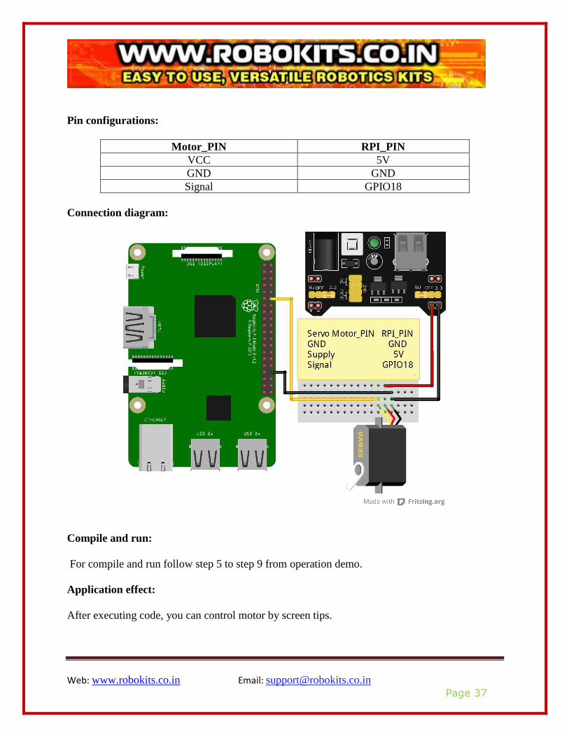
Pin configurations:
Motor_PIN RPI_PIN
VCC 5V
GND GND
Signal GPIO18
Connection diagram:
Compile and run:
For compile and run follow step 5 to step 9 from operation demo.
Application effect:
After executing code, you can control motor by screen tips.
Web: www.robokits.co.in Email: [email protected]
Page 38
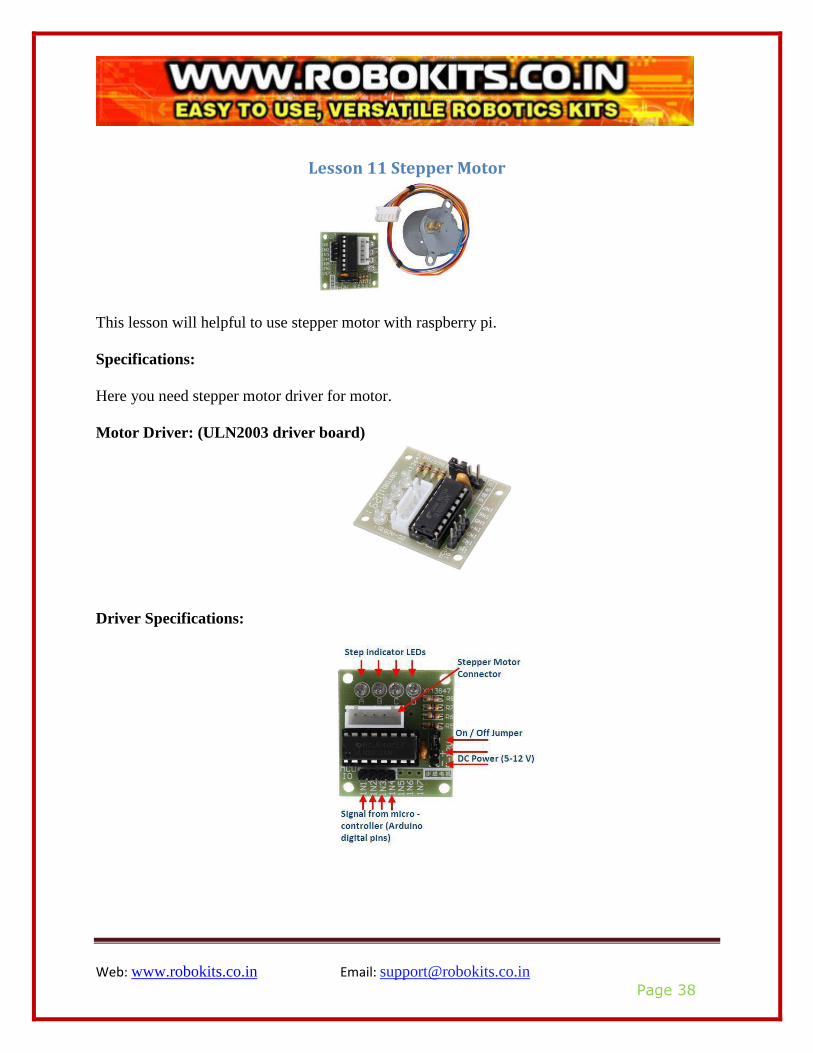
Lesson 11 Stepper Motor
This lesson will helpful to use stepper motor with raspberry pi.
Specifications:
Here you need stepper motor driver for motor.
Motor Driver: (ULN2003 driver board)
Driver Specifications:
Web: www.robokits.co.in Email: [email protected]
Page 39
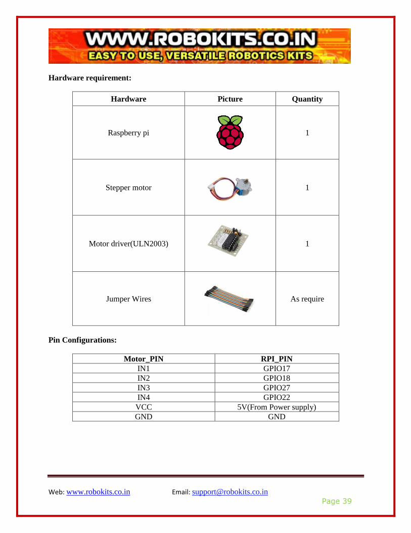
Hardware requirement:
Hardware Picture Quantity
Raspberry pi
1
Stepper motor
1
Motor driver(ULN2003)
1
Jumper Wires
As require
Pin Configurations:
Motor_PIN RPI_PIN
IN1 GPIO17
IN2 GPIO18
IN3 GPIO27
IN4 GPIO22
VCC 5V(From Power supply)
GND GND
Web: www.robokits.co.in Email: [email protected]
Page 40
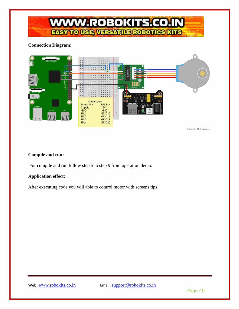
Connection Diagram:
Compile and run:
For compile and run follow step 5 to step 9 from operation demo.
Application effect:
After executing code you will able to control motor with screens tips.
Web: www.robokits.co.in Email: [email protected]
Page 41
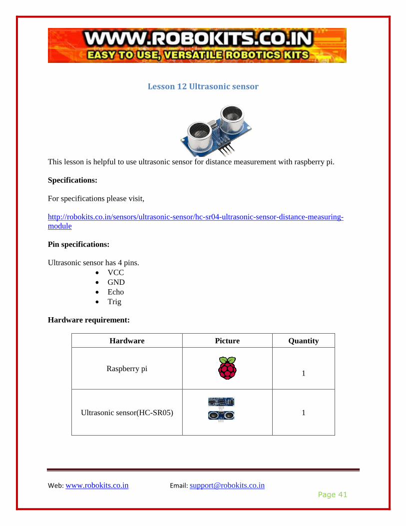
Lesson 12 Ultrasonic sensor
This lesson is helpful to use ultrasonic sensor for distance measurement with raspberry pi.
Specifications:
For specifications please visit,
http://robokits.co.in/sensors/ultrasonic-sensor/hc-sr04-ultrasonic-sensor-distance-measuring-
module
Pin specifications:
Ultrasonic sensor has 4 pins.
• VCC
• GND
• Echo
• Trig
Hardware requirement:
Hardware Picture Quantity
Raspberry pi
1
Ultrasonic sensor(HC-SR05)
1

Web: www.robokits.co.in Email: [email protected]
Page 42
Bread Board
1
Jumper Wires
As Require
Pin Configuration:
Sensor_PIN RPI_PIN
VCC 5V
GND GND
Echo GPIO24
Trig GPIO23
Connection diagram:
Web: www.robokits.co.in Email: [email protected]
Page 43
Compile and run:
For compile and run follow step 5 to step 9 from operation demo.
Application effect:
After executing code you will see parameters returned by ultrasonic sensor.
Web: www.robokits.co.in Email: [email protected]
Page 44
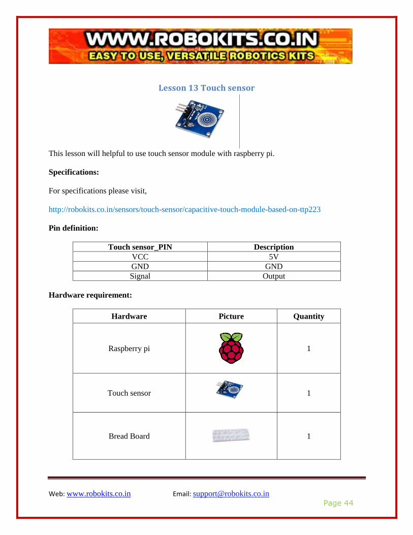
Lesson 13 Touch sensor
This lesson will helpful to use touch sensor module with raspberry pi.
Specifications:
For specifications please visit,
http://robokits.co.in/sensors/touch-sensor/capacitive-touch-module-based-on-ttp223
Pin definition:
Touch sensor_PIN Description
VCC 5V
GND GND
Signal Output
Hardware requirement:
Hardware Picture Quantity
Raspberry pi
1
Touch sensor
1
Bread Board
1
Web: www.robokits.co.in Email: [email protected]
Page 45
Jumper Wires
As require
RGB Module
1
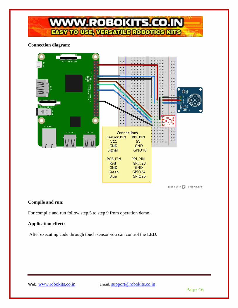
Pin configurations:
Sensor_PIN RPI_PIN
VCC 5V
GND GND
Signal GPIO18
RGB_PIN RPI_PIN
Red GPIO23
GND GND
Green GPIO24
Blue GPIO25
Web: www.robokits.co.in Email: [email protected]
Page 46
Connection diagram:
Compile and run:
For compile and run follow step 5 to step 9 from operation demo.
Application effect:
After executing code through touch sensor you can control the LED.
Web: www.robokits.co.in Email: [email protected]
Page 47
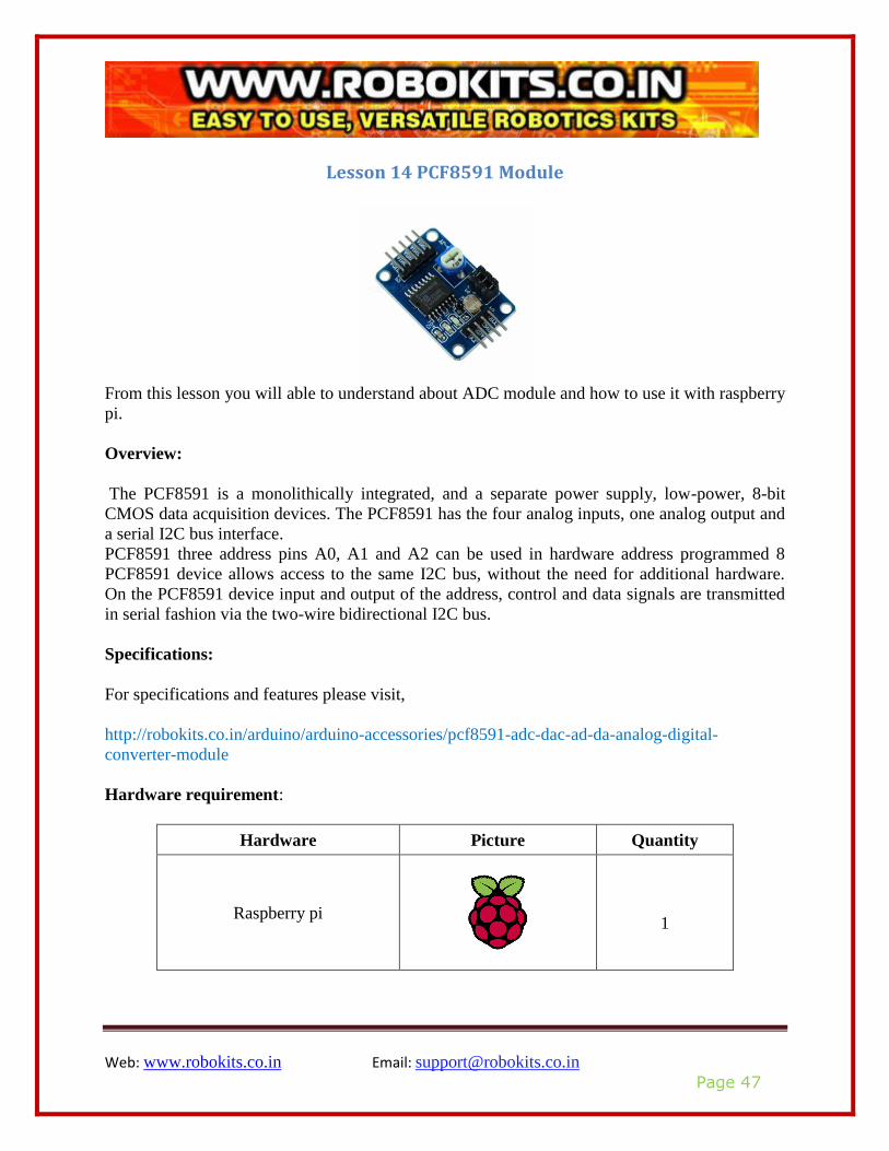
Lesson 14 PCF8591 Module
From this lesson you will able to understand about ADC module and how to use it with raspberry
pi.
Overview:
The PCF8591 is a monolithically integrated, and a separate power supply, low-power, 8-bit
CMOS data acquisition devices. The PCF8591 has the four analog inputs, one analog output and
a serial I2C bus interface.
PCF8591 three address pins A0, A1 and A2 can be used in hardware address programmed 8
PCF8591 device allows access to the same I2C bus, without the need for additional hardware.
On the PCF8591 device input and output of the address, control and data signals are transmitted
in serial fashion via the two-wire bidirectional I2C bus.
Specifications:
For specifications and features please visit,
http://robokits.co.in/arduino/arduino-accessories/pcf8591-adc-dac-ad-da-analog-digital-
converter-module
Hardware requirement:
Hardware Picture Quantity
Raspberry pi
1
Web: www.robokits.co.in Email: [email protected]
Page 48
PCF8591 Module
1
Bread Board
1
Jumper Wires
As require
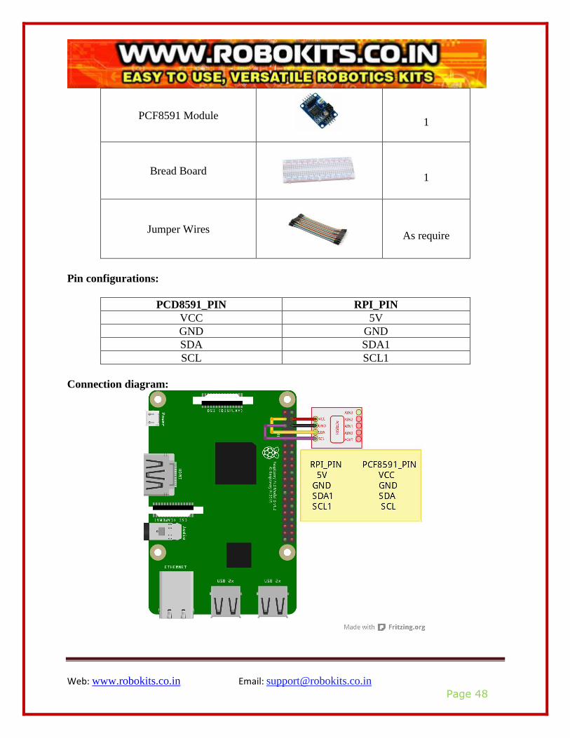
Pin configurations:
PCD8591_PIN RPI_PIN
VCC 5V
GND GND
SDA SDA1
SCL SCL1
Connection diagram:
Web: www.robokits.co.in Email: [email protected]
Page 49
Compile and run:
Tips: Refer to the operation demo (Step4 to Step7).
If print: Unable to open I2C device
You need to open IIC.
Enter Desktop: Preferences Raspberry Pi
Configuration Interfaces Enabled I2C reboot.
Application effect:
After executing code you will find data from analog photo-resistance sensor.
Web: www.robokits.co.in Email: [email protected]
Page 50
Lesson 15 Flame sensor
This lesson will helpful to use flame sensor with raspberry pi
Overview:
Flame Detection Sensor Module is sensitive to the flame, but also can detect ordinary light.
Usually used as a flame alarm.
It detects a flame or a light source of a wavelength in the range of 760nm-1100 nm. Detection
point of about 60 degrees is particularly sensitive to the flame spectrum. Sensitivity is adjustable,
stable performance.
Specifications:
For specifications please visit:
http://robokits.co.in/sensors/temperature/flame-sensor-module
Pin definition:
Flame sensor_PIN Description
VCC 5V
GND GND
AO For analog output interface
DO For digital output interface

Web: www.robokits.co.in Email: [email protected]
Page 51
Hardware requirement:
Hardware Picture Quantity
Raspberry pi
1
Flame sensor
1
Bread Board
1
Jumper Wires
As require
Pin configurations:
Diode_PIN RPI_PIN
Long pin(+ve) GND
Short pin(GND) GPIO17
Web: www.robokits.co.in Email: [email protected]
Page 52
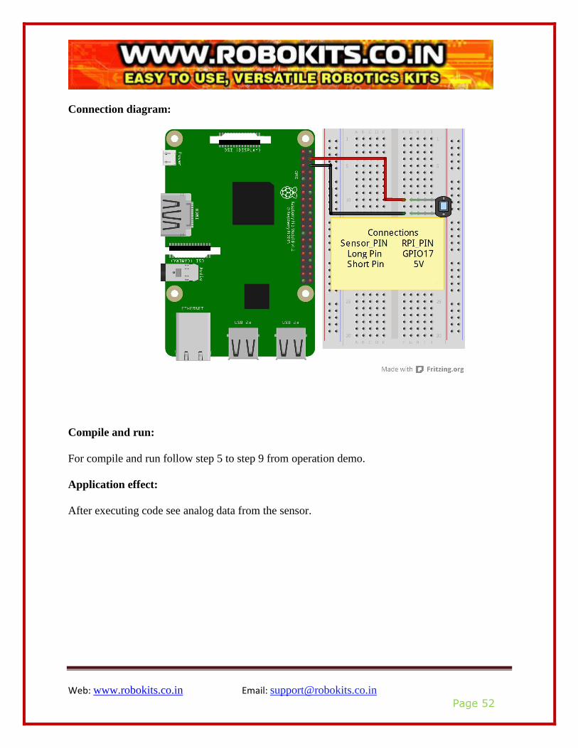
Connection diagram:
Compile and run:
For compile and run follow step 5 to step 9 from operation demo.
Application effect:
After executing code see analog data from the sensor.
Web: www.robokits.co.in Email: [email protected]
Page 53
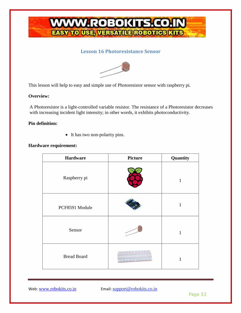
Lesson 16 Photoresistance Sensor
This lesson will help to easy and simple use of Photoresistor sensor with raspberry pi.
Overview:
A Photoresistor is a light-controlled variable resistor. The resistance of a Photoresistor decreases
with increasing incident light intensity; in other words, it exhibits photoconductivity.
Pin definition:
• It has two non-polarity pins.
Hardware requirement:
Hardware Picture Quantity
Raspberry pi
1
PCF8591 Module
1
Sensor
1
Bread Board
1
Web: www.robokits.co.in Email: [email protected]
Page 54
Jumper Wires
As require
Resistor(10K)
1
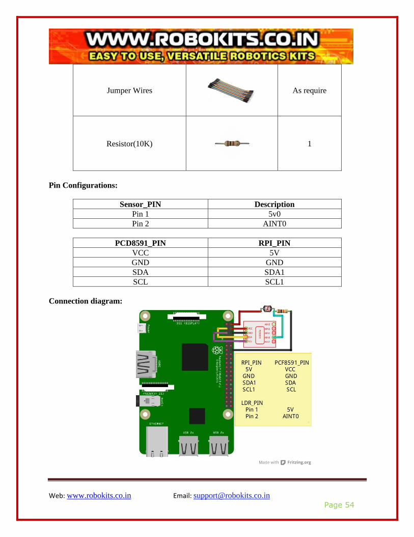
Pin Configurations:
Sensor_PIN Description
Pin 1 5v0
Pin 2 AINT0
PCD8591_PIN RPI_PIN
VCC 5V
GND GND
SDA SDA1
SCL SCL1
Connection diagram:
Web: www.robokits.co.in Email: [email protected]
Page 55
Compile and run:
For compile and run follow step 5 to step 9 from operation demo.
Application effect:
After executing code you will find data from analog photo-resistance sensor.

Web: www.robokits.co.in Email: [email protected]
Page 56
Lesson 17 Thermistor sensor
By this lesson you will able to use Thermistor sensor with raspberry pi.
Overview:
The ZX_Thermometer is a temperature sensing module that uses a NTC (Negative Temperature
Coefficient) Thermistor device. The output from the NTC Thermistor is converted to a voltage
that is directly proportional to the temperature. The Thermistor can be placed some distance
away.
Pin definition:
Sensor_PIN Description
VCC 5V
GND GND
AO For analog output interface
DO For digital output interface
Hardware details:
Hardware Picture Quantity
Raspberry pi
1
Thermistor
1
Web: www.robokits.co.in Email: [email protected]
Page 57
Bread Board
1
Jumper Wires
As require
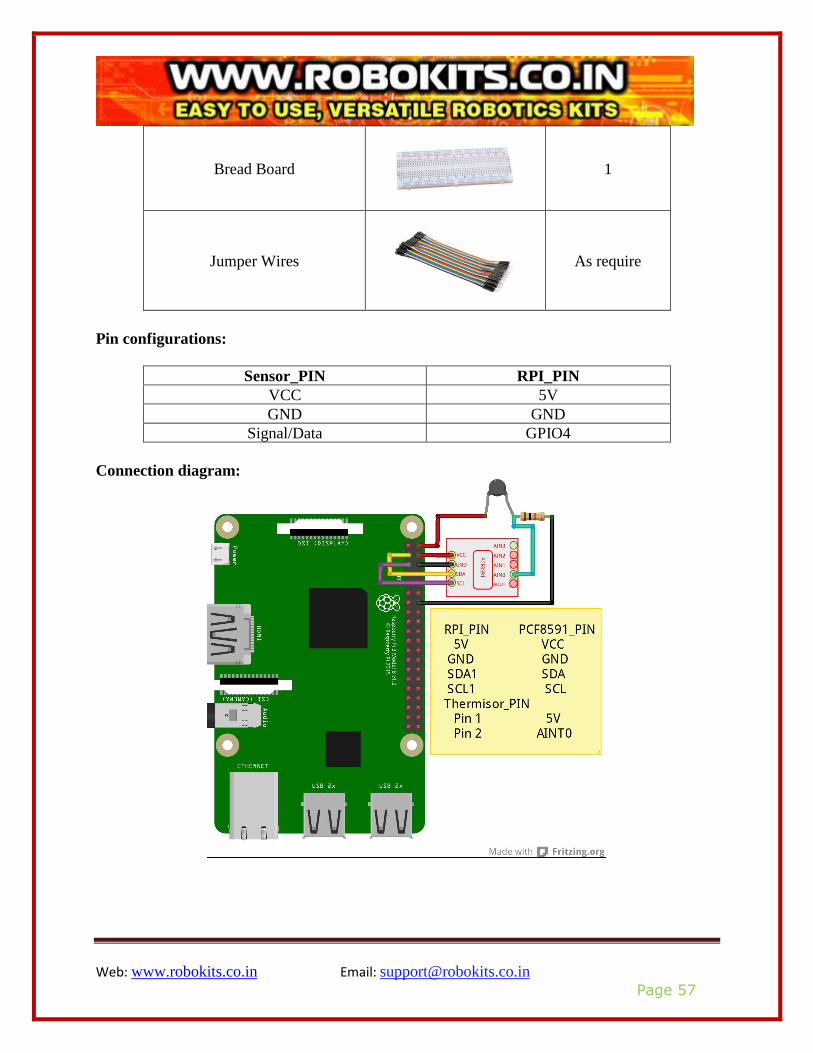
Pin configurations:
Sensor_PIN RPI_PIN
VCC 5V
GND GND
Signal/Data GPIO4
Connection diagram:

Web: www.robokits.co.in Email: [email protected]
Page 58
Compile and run:
For compile and run follow step 5 to step 9 from operation demo.
Application effect:
After executing code, you will see value of Thermistor sensor.
Web: www.robokits.co.in Email: [email protected]
Page 59
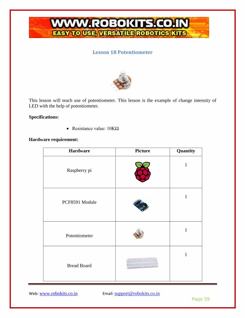
Lesson 18 Potentiometer
This lesson will teach use of potentiometer. This lesson is the example of change intensity of
LED with the help of potentiometer.
Specifications:
• Resistance value: 10KΩ
Hardware requirement:
Hardware Picture Quantity
Raspberry pi
1
PCF8591 Module
1
Potentiometer
1
Bread Board
1
Web: www.robokits.co.in Email: [email protected]
Page 60
Jumper Wires
As require
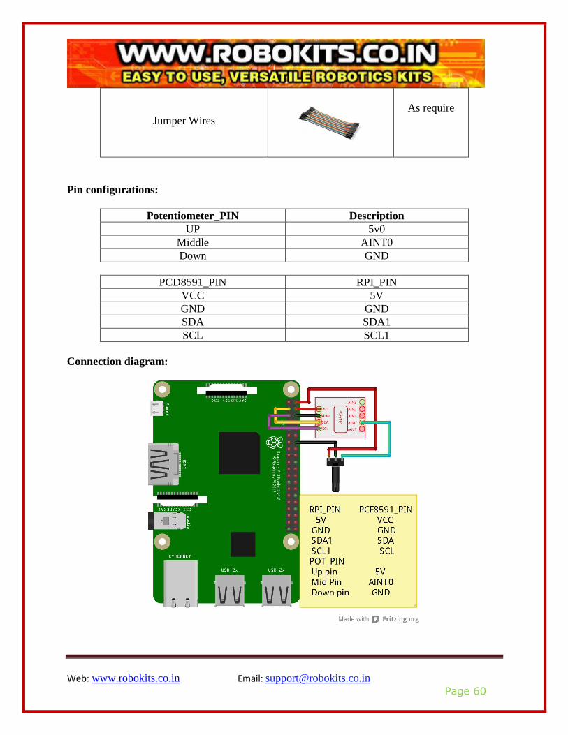
Pin configurations:
Potentiometer_PIN Description
UP 5v0
Middle AINT0
Down GND
PCD8591_PIN RPI_PIN
VCC 5V
GND GND
SDA SDA1
SCL SCL1
Connection diagram:

Web: www.robokits.co.in Email: [email protected]
Page 61
Compile and run:
For compile and run follow step 5 to step 9 from operation demo.
Application effect:
After executing code and rotating potentiometer you can see the analog value of potentiometer.

Web: www.robokits.co.in Email: [email protected]
Page 62
Lesson 19 Water level sensor
This lesson will help to understand simple and easy use of water level sensor with raspberry pi.
Overview:
Water Sensor water level sensor is an easy-to-use, high level/drop recognition sensor, which is
obtained by having a series of parallel wires exposed traces measured droplets/water volume in
order to determine the water level. Easy to complete water to analog signal conversion and
output analog values can be directly read Arduino development board to achieve the level alarm
effect.
Specifications:
• Operating voltage: DC3-5V
• Operating current: less than 20mA
• Sensor Type: Analog
• Detection Area: 40mmx16mm
• Humidity: 10% -90% non-condensing
• Product Dimensions: 62mmx20mmx8mm
Pin definition:
Sensor_PIN Description
VCC 5V
GND GND
Output Analog data
Web: www.robokits.co.in Email: [email protected]
Page 63
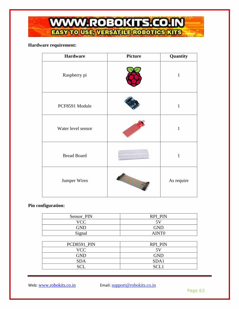
Hardware requirement:
Hardware Picture Quantity
Raspberry pi
1
PCF8591 Module
1
Water level sensor
1
Bread Board
1
Jumper Wires
As require
Pin configuration:
Sensor_PIN RPI_PIN
VCC 5V
GND GND
Signal AINT0
PCD8591_PIN RPI_PIN
VCC 5V
GND GND
SDA SDA1
SCL SCL1
Web: www.robokits.co.in Email: [email protected]
Page 64
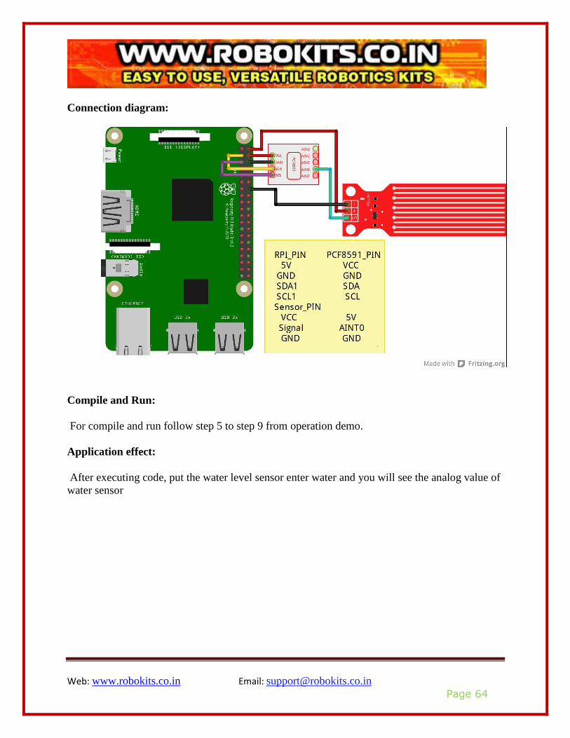
Connection diagram:
Compile and Run:
For compile and run follow step 5 to step 9 from operation demo.
Application effect:
After executing code, put the water level sensor enter water and you will see the analog value of
water sensor
Web: www.robokits.co.in Email: [email protected]
Page 65
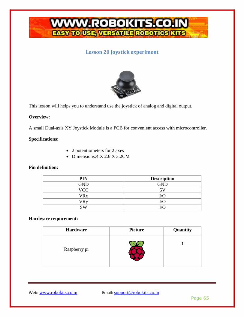
Lesson 20 Joystick experiment
This lesson will helps you to understand use the joystick of analog and digital output.
Overview:
A small Dual-axis XY Joystick Module is a PCB for convenient access with microcontroller.
Specifications:
• 2 potentiometers for 2 axes
• Dimensions:4 X 2.6 X 3.2CM
Pin definition:
PIN Description
GND GND
VCC 5V
VRx I/O
VRy I/O
SW I/O
Hardware requirement:
Hardware Picture Quantity
Raspberry pi
1
Web: www.robokits.co.in Email: [email protected]
Page 66
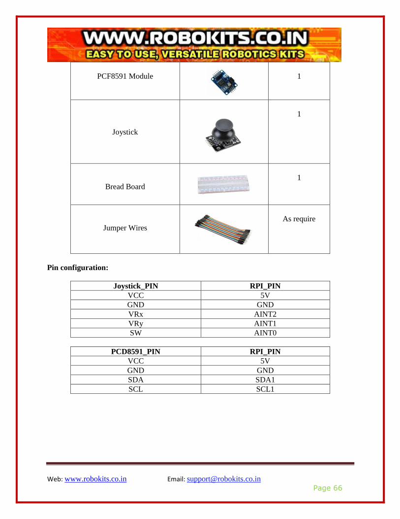
PCF8591 Module
1
Joystick
1
Bread Board
1
Jumper Wires
As require
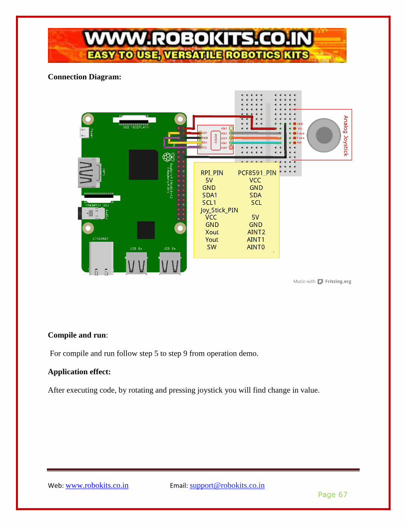
Pin configuration:
Joystick_PIN RPI_PIN
VCC 5V
GND GND
VRx AINT2
VRy AINT1
SW AINT0
PCD8591_PIN RPI_PIN
VCC 5V
GND GND
SDA SDA1
SCL SCL1
Web: www.robokits.co.in Email: [email protected]
Page 67
Connection Diagram:
Compile and run:
For compile and run follow step 5 to step 9 from operation demo.
Application effect:
After executing code, by rotating and pressing joystick you will find change in value.
Web: www.robokits.co.in Email: [email protected]
Page 68
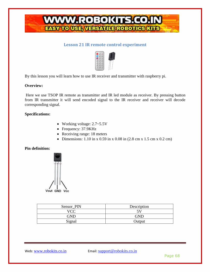
Lesson 21 IR remote control experiment
By this lesson you will learn how to use IR receiver and transmitter with raspberry pi.
Overview:
Here we use TSOP IR remote as transmitter and IR led module as receiver. By pressing button
from IR transmitter it will send encoded signal to the IR receiver and receiver will decode
corresponding signal.
Specifications:
• Working voltage: 2.7~5.5V
• Frequency: 37.9KHz
• Receiving range: 18 meters
• Dimensions: 1.10 in x 0.59 in x 0.08 in (2.8 cm x 1.5 cm x 0.2 cm)
Pin definition:
Sensor_PIN Description
VCC 5V
GND GND
Signal Output
Web: www.robokits.co.in Email: [email protected]
Page 69
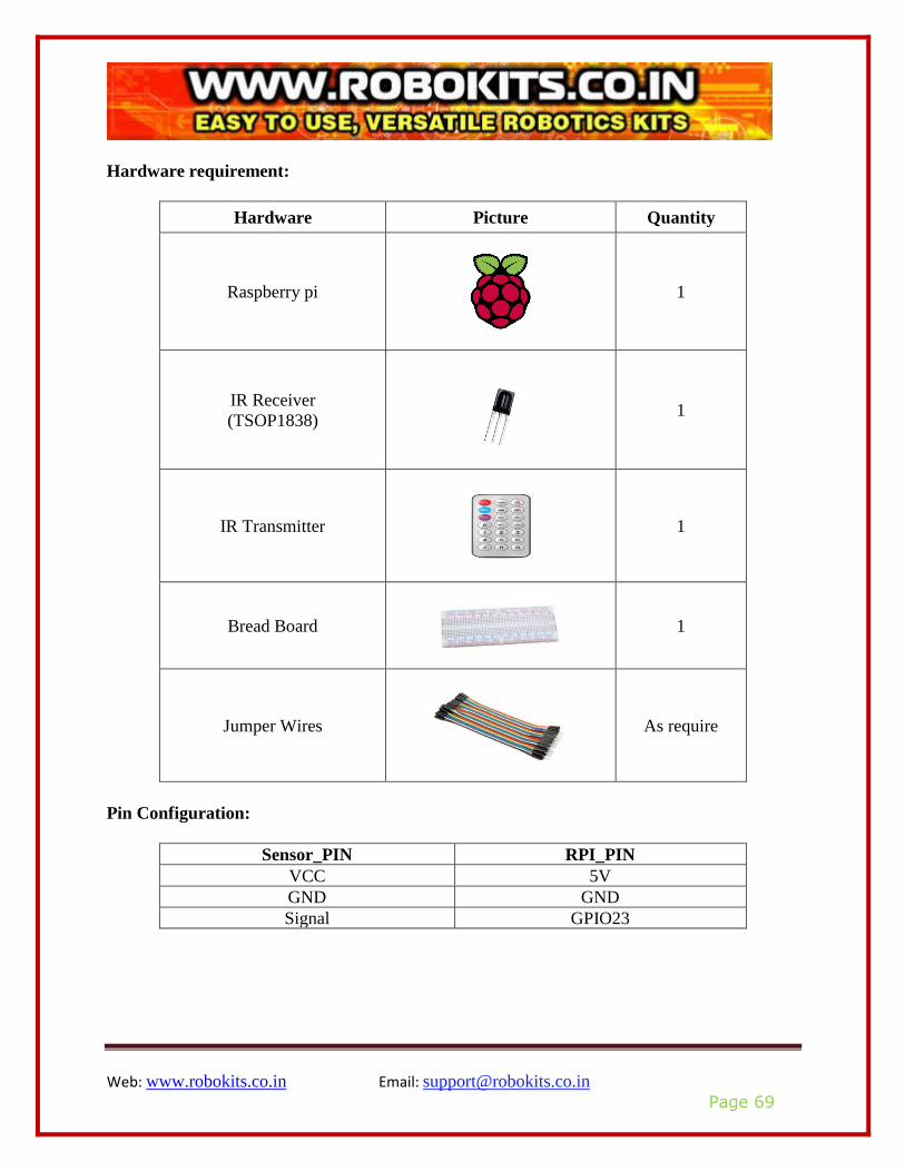
Hardware requirement:
Hardware Picture Quantity
Raspberry pi
1
IR Receiver
(TSOP1838)
1
IR Transmitter
1
Bread Board
1
Jumper Wires
As require
Pin Configuration:
Sensor_PIN RPI_PIN
VCC 5V
GND GND
Signal GPIO23
Web: www.robokits.co.in Email: [email protected]
Page 70
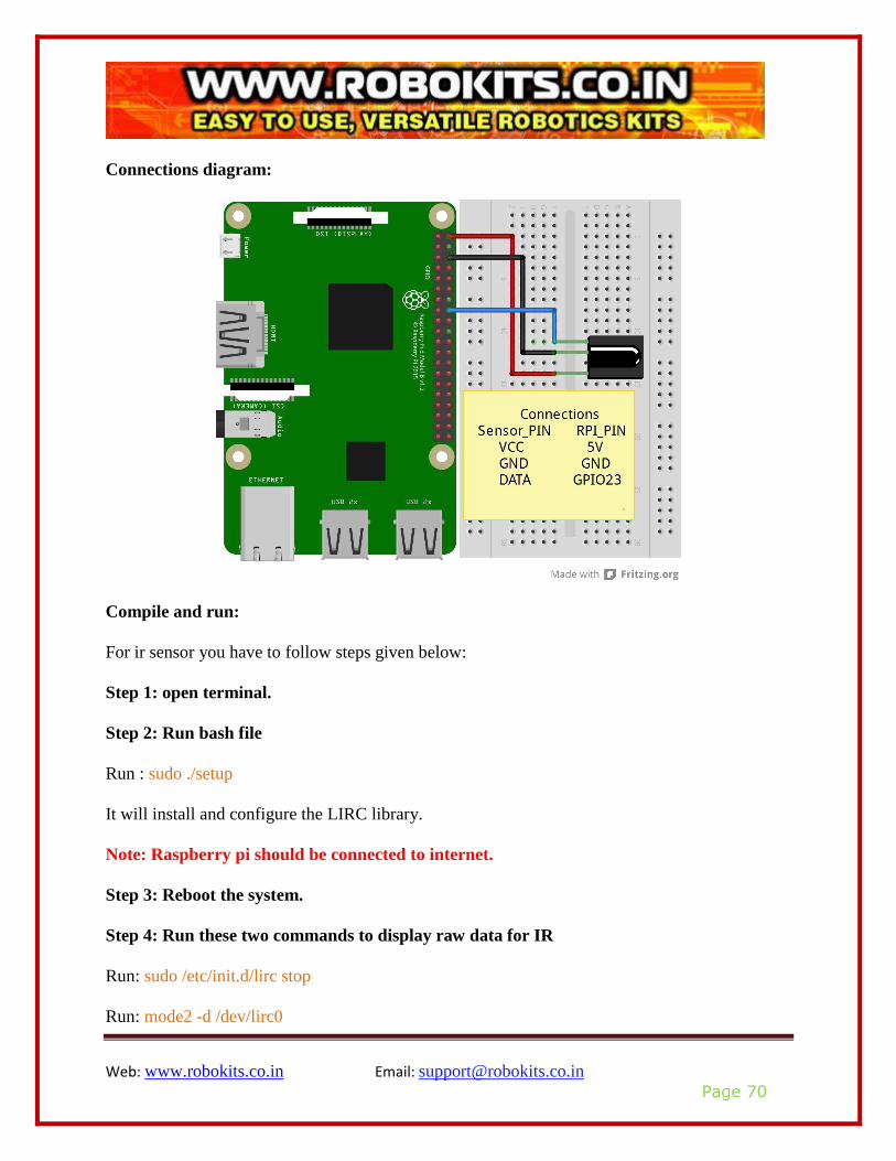
Connections diagram:
Compile and run:
For ir sensor you have to follow steps given below:
Step 1: open terminal.
Step 2: Run bash file
Run : sudo ./setup
It will install and configure the LIRC library.
Note: Raspberry pi should be connected to internet.
Step 3: Reboot the system.
Step 4: Run these two commands to display raw data for IR
Run: sudo /etc/init.d/lirc stop
Run: mode2 -d /dev/lirc0

Web: www.robokits.co.in Email: [email protected]
Page 71
Application effect:
After executing code, by pressing button you will find that each button has corresponding coding
and get following window,
Web: www.robokits.co.in Email: [email protected]
Page 72
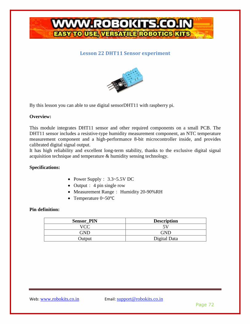
Lesson 22 DHT11 Sensor experiment
By this lesson you can able to use digital sensorDHT11 with raspberry pi.
Overview:
This module integrates DHT11 sensor and other required components on a small PCB. The
DHT11 sensor includes a resistive-type humidity measurement component, an NTC temperature
measurement component and a high-performance 8-bit microcontroller inside, and provides
calibrated digital signal output.
It has high reliability and excellent long-term stability, thanks to the exclusive digital signal
acquisition technique and temperature & humidity sensing technology.
Specifications:
• Power Supply: 3.3~5.5V DC
• Output: 4 pin single row
• Measurement Range: Humidity 20-90%RH
• Temperature 0~50
Pin definition:
Sensor_PIN Description
VCC 5V
GND GND
Output Digital Data
Web: www.robokits.co.in Email: [email protected]
Page 73
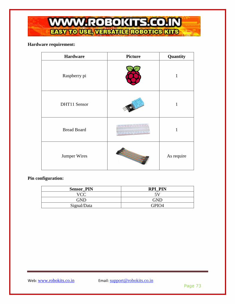
Hardware requirement:
Hardware Picture Quantity
Raspberry pi
1
DHT11 Sensor
1
Bread Board
1
Jumper Wires
As require
Pin configuration:
Sensor_PIN RPI_PIN
VCC 5V
GND GND
Signal/Data GPIO4
Web: www.robokits.co.in Email: [email protected]
Page 74
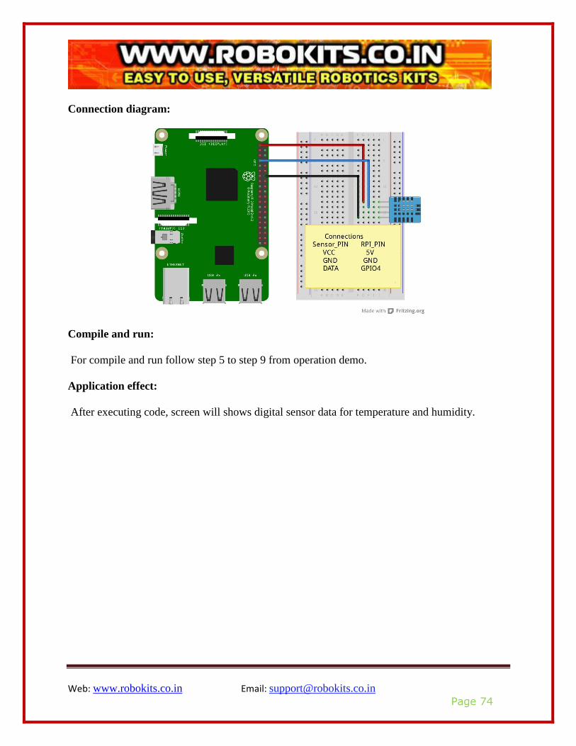
Connection diagram:
Compile and run:
For compile and run follow step 5 to step 9 from operation demo.
Application effect:
After executing code, screen will shows digital sensor data for temperature and humidity.

Web: www.robokits.co.in Email: [email protected]
Page 75
Lesson 23 Serial LCD
In this lesson you will learn how to use LCD with raspberry pi board.
Overview:
This LCD can easily wire up with any device or any controller. This LCD works on the UART
protocol of communication. You can also use LCD to display sensors reading and status. By
adjust value of potentiometer you can manage brightness of LCD.
Specifications:
• Number of Characters: 16 characters x 2 line
• Character Format 5 x 7 dots with cursor
Pin configuration:
Web: www.robokits.co.in Email: [email protected]
Page 76
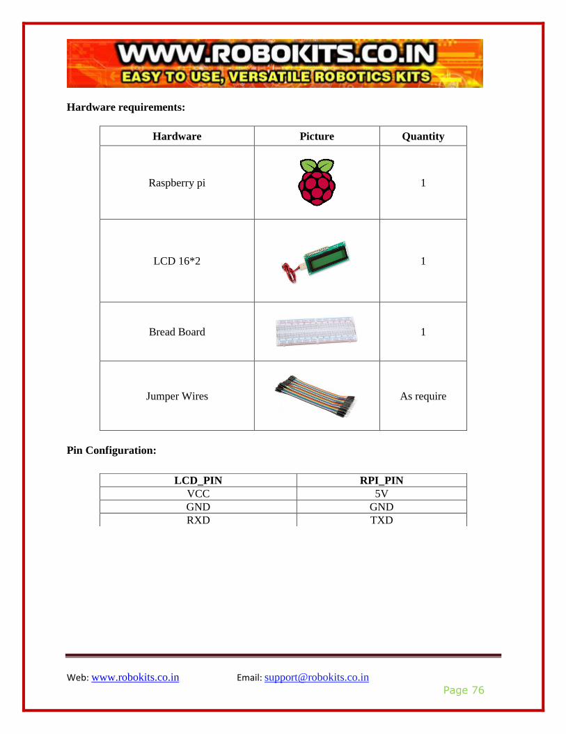
Hardware requirements:
Hardware Picture Quantity
Raspberry pi
1
LCD 16*2
1
Bread Board
1
Jumper Wires
As require
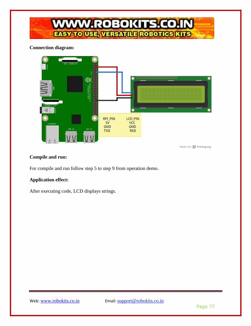
Pin Configuration:
LCD_PIN RPI_PIN
VCC 5V
GND GND
RXD TXD
Web: www.robokits.co.in Email: [email protected]
Page 77
Connection diagram:
Compile and run:
For compile and run follow step 5 to step 9 from operation demo.
Application effect:
After executing code, LCD displays strings.


![Measuring ECG Signal Using e-Health Sensor Platform€¦ · PandaBoard, Raspberry-pi are various single board computers. In this study, Raspberry Pi [11], [12] is preferred for being](https://img.pdfslide.us/doc/110x75/5ecc1912b87aaf7c37004a86/measuring-ecg-signal-using-e-health-sensor-platform-pandaboard-raspberry-pi-are.jpg)