Embed Size (px)
Citation preview


INTRODUCTION
© 2005 Hitachi Construction Machinery Co., Ltd. All rights reserved.
Read this manual carefully to learn how to operate and service your machine correctly. Failure to do so could result in personal injury or equipment damage. This standard specification machine can be operated under the following conditions without being modified. Atmospheric Temperature: −20°C to 40°C (−4°F to 104°F) Altitude: 0 m to 1500 m (0 ft to 4900 ft) In case the machine is used under conditions other than described above, consult your nearest Hitachi dealer. This manual should be considered a permanent part of your machine and should remain with the machine when you sell it. This machine is of metric design. Measurements in this manual are metric. Use only metric hardware and tools as specified. • SI Units (International System of Units) are used in
this manual. For reference MKS system units and English units are also indicated in parentheses after the SI units. Example : 24.5 MPa (250 kgf/cm2, 3560 psi)
Right-hand and left-hand sides are determined by facing in the direction of forward travel. Write product identification numbers in the Machine Numbers section. Accurately record all the numbers to help in tracing the machine should it be stolen. Your dealer also needs these numbers when you order parts. If this manual is kept on the machine, also file the identification numbers in a secure place off the machine.
Warranty is provided as a part of Hitachi's support program for customers who operate and maintain their equipment as described in this manual. The warranty is explained on the warranty certificate which you should have received from your dealer. This warranty provides you the assurance that Hitachi will back its products where defects appear within the warranty period. In some circumstances, Hitachi also provides field improvements, often without charge to the customer, even if the product is out of warranty. Should the equipment be abused, or modified to change its performance beyond the original factory specifications, the warranty will become void and field improvements may be denied. Setting fuel delivery above specifications or otherwise overpowering machines will result in such action. Only qualified, experienced operators officially licensed (according to local law) should be allowed to operate the machine. Moreover, only officially licensed personnel should be allowed to inspect and service the machine. Prior to operating this machine in a country other than a country of its intended use, it may be necessary to make modifications to it so that it complies with the local standards (including safety standards) and requirements of that particular country. Please do not operate this machine outside of the country of its intended use until such compliance has been confirmed. Please contact Hitachi Construction Machinery Co., Ltd. or any of our authorized distributor or dealer if you have any questions concerning compliance.
All information, illustrations and specifications in this manual are based on the latest product information available at the time of publication. The right is reserved to make changes at any time without notice.

MACHINE NUMBERSSAFETYSAFETY SIGNSCOMPONENTS NAMEOPERATOR’S STATIONBREAK-IN OPERATING ENGINEDRIVING THE MACHINE
TRANSPORTINGMAINTENANCECONSUMABLE PARTS LISTMAINTENENCE UNDER SPECIAL ENVIRONMENTAL CONDITIONS
OPERATION
STORAGE TROUBLESHOOTINGSPECIFICATIONSREFERENCEINDEX

CONTENTS
MACHINE NUMBERS SAFETY Recognize Safety Information ............................ S-1 Understand Signal Words................................... S-1 Follow Safety Instructions................................... S-2 Prepare for Emergencies.................................... S-2 Wear Protective Clothing.................................... S-3 Protect Against Noise ......................................... S-3 Inspect Machine.................................................. S-3 Tidy Up Inside Cab ............................................. S-4 Use Handholds and Steps.................................. S-4 Adjust the Operator�s Seat.................................. S-5 Fasten Your Seat Belt......................................... S-5 Move and Operate Machine Safely .................... S-6 Operate Only from Operator�s Seat.................... S-7 Jump Starting...................................................... S-7 Keep Riders Off Machine.................................... S-7 Investigate Job Site Beforehand......................... S-8 Protect Against Falling Stones and Debris ......... S-9 Provide Signals for Jobs Involving Multiple Numbers of Machines ..................... S-9 Confirm Direction of Machine to be Driven......... S-9 Drive Machine Safely........................................ S-10 Avoid Injury from Rollaway Accidents .............. S-11 Avoid Injury from Back-Over and Swing Accidents .................................. S-12 Keep Person Clear from Working Area ............ S-13 Never Position Bucket Over Anyone ................ S-13 Avoid Undercutting ........................................... S-13 Avoid Tipping .................................................... S-14 Never Undercut a High Bank............................ S-14 Dig with Caution................................................ S-15 Operate with Caution ........................................ S-15 Avoid Power Lines ............................................ S-15 Do Not Use for Craning Operations.................. S-16 Protect Against Flying Debris ........................... S-16 Park Machine Safely......................................... S-17 Handle Fluids Safely � Avoid Fires................... S-17 Safety Transporting .......................................... S-18 Practice Safe Maintenance............................... S-19 Warn Others of Service Work........................... S-20 Support Machine Properly ................................ S-21 Stay Clear of Moving Parts ............................... S-21 Prevent Parts from Flying ................................. S-21 Store Attachments Safely ................................. S-22 Prevent Burns ................................................... S-22 Replace Rubber Hoses Periodically ................. S-23 Avoid High-Pressure Fluids .............................. S-23 Prevent Fires .................................................... S-24 Evacuating in Case of Fire................................ S-26 Beware of Exhaust Fumes................................ S-26 Precautions for Welding and Grinding.............. S-27 Avoid Heating Near Pressurized Fluid Lines.... S-27
Avoid Applying Heat to Lines Containing Flammable Fluids .....................S-27 Remove Paint before Welding or Heating.........S-28 Prevent Battery Explosions ...............................S-28 Precautions for Handling Refrigerant................S-29 Handle Chemical Products Safely ....................S-29 Dispose of Waste Properly................................S-30 SAFETY SIGNS .........................................S-31 COMPONENTS NAME .............................. 1-1 OPERATOR�S STATION Pedals, Levers and Monitor Panel ...................... 1-2 Key Switch........................................................... 1-4 Switch Panel........................................................ 1-4 Monitor Panel ...................................................... 1-5 Coolant Temperature Gauge .............................. 1-5 Fuel Gauge.......................................................... 1-5 System Failure Indicator ..................................... 1-6 Engine Oil Pressure Indicator ............................. 1-6 Overheat Indicator............................................... 1-6 Fuel Level Indicator ............................................. 1-6 Alternator Indicator .............................................. 1-7 Preheat Indicator ................................................. 1-7 Fast Travel Mode Indicator ................................. 1-7 Liquid Crystal display (LCD), Display Selection Switch, and Set Switch..... 1-8 How to Operate Trip Meter.................................. 1-9 Auto-Idle Mode Switch ...................................... 1-11 Air Conditioner Operation.................................. 1-12 Tips for Air Conditioner Usage.......................... 1-14 Radio (Cab Equipped Machines) ...................... 1-15 AM/FM Radio Operation ................................... 1-16 Cab Door Release lever (Only on cab-equipped machines).............. 1-18 Opening/Closing Cab Front Window (Only on cab-equipped machines) ............ 1-19 Adjusting Operator�s Seat ................................. 1-20 Tool and Operator�s manual Boxes .................. 1-20 Opening/Closing Cab Rear Window (Cab-equipped machines)........................... 1-21 Emergency Exit (Cab-equipped machines) ...... 1-22 Seat Belt (Optional) ........................................... 1-23 Cab Light (Cab-equipped machines) ................ 1-23 BREAK-IN Breaking in New Machine ................................... 2-1 OPERATING ENGINE Before Starting Engine ........................................ 3-1 Starting Engine.................................................... 3-2 Starting in Cold Weather ..................................... 3-3 Check Machine After Starting Engine ................. 3-4 Using Booster Batteries ...................................... 3-5 Stopping the Engine............................................ 3-6

CONTENTS
DRIVING THE MACHINE Travel Levers and Pedals ....................................4-1 Travel Mode Switch .............................................4-3 Precautions for Traveling.....................................4-4 Traveling on Soft Ground.....................................4-5 Raise One Track Using Boom and Arm ..............4-5 Towing Machine...................................................4-6 Driving In Water or on Soft Ground .....................4-7 Precautions for Traveling on Slopes....................4-8 Parking and Stopping on Slope ...........................4-9 Parking on Slopes................................................4-9 OPERATION Control Lever (ISO Excavator Pattern)................5-1 Control Lever (H-Pattern: HITACHI Excavator Pattern).......5-2 Control Lever (SAE-Backhoe Pattern) --- If Equipped (2 Way Multi Valve) ...............5-3 Boom-Swing Pedal ............................................5-4 Auxiliary Pedal (Optional) ....................................5-5 Blade Lever..........................................................5-6 Precautions for Blade Operation .........................5-7 Pilot Control Shut-Off Lever.................................5-8 Warming Up Operation........................................5-9 Warming Up in Cold Weather..............................5-9 Auto-Idle Control (Except ZX27U-2) ..................5-10 Precautions for Operations................................5-11 Operate Machine Safely ....................................5-11 Operating Backhoe ............................................5-12 Grading Operation .............................................5-13 Avoid Driving Bucket Teeth Into Ground ...........5-13 Avoid Abusive Operation ...................................5-13 Avoid Striking with Bucket .................................5-14 Avoid Excavation Using Upperstructure and/or Boom Swing Power ..........................5-14 Use Correct Track Shoe ....................................5-14 Avoid Other than Specified Machine Operations ...................................................5-15 Precautions for Using Bucket Hook...................5-16 Boom Cylinder May Hit Blade............................5-16 Avoid Hitting Blade with Bucket.........................5-17 Avoid Colliding Blade Against Rocks.................5-17 Avoid Colliding Boom Cylinder with Track.........5-17 Precautions for Installing Wide Bucket or Special Type Bucket................................5-17 Using Rubber Crawler .......................................5-18 Hydraulic Breaker (Optional) .............................5-20 Crusher Operation (Optional) ............................5-23 Precautions for After Operating the Machine ....5-24 Auxiliary Flow Rate Control (Optional) (Except ZX27U-2)........................5-25 TRANSPORTING Transporting by Road ..........................................6-1 Trailer Loading/Unloading ...................................6-1 Loading ................................................................6-2
Securing the Machine to the Trailer for Transportation.......................................... 6-3 Unloading ............................................................ 6-4 Lifting Machine with Crane.................................. 6-5 MAINTENANCE Procedures........................................................... 7-1 Prepare Machine for Inspection/Maintenance .... 7-2 Opening/Closing Engine Access Covers ............ 7-3 Opening/Closing Tank Covers ............................ 7-4 Daily Inspection ................................................... 7-5 Periodic Replacement of Parts............................ 7-6 Maintenance Guide ............................................. 7-7 The Brand Names of Recommended Oils and Lubricants ..................................... 7-10 A. Greasing...................................................... 7-11 Front Joint Pins ........................................... 7-11 Bucket and Link Pins................................... 7-14 Blade Pins ................................................... 7-14 Precautions for Front Attachment and Blade Removal ...................................... 7-14 Swing Bearing ............................................. 7-15 Swing Internal Gear .................................... 7-16 Control Lever Universal Joint...................... 7-16 B. Engine ......................................................... 7-17 Engine Oil.................................................... 7-17 Change Engine Oil ...................................... 7-17 Replace Engine Oil Filter ............................ 7-17 C. Transmission............................................... 7-19 Travel Reduction Gear................................ 7-19 D. Hydraulic System ........................................ 7-21 Inspection and Maintenance of Hydraulic Equipment ............................. 7-21 Check Hydraulic Oil Level........................... 7-22 Drain Hydraulic Oil Tank Sump................... 7-23 Change Hydraulic Oil .................................. 7-24 Clean Suction Filter..................................... 7-27 Replace Full Flow Filter .............................. 7-28 Replace Pilot Filter ...................................... 7-29 Check Hoses and Lines .............................. 7-31 E. Fuel System ................................................ 7-36 Check Water Separator .............................. 7-37 Drain Fuel Tank Sump ................................ 7-37 Replace Fuel Filter ...................................... 7-38 Check Fuel Hoses....................................... 7-39 F. Air Cleaner .................................................. 7-40 Clean the Air Cleaner Element ................... 7-40 Replace the Air Cleaner Element................ 7-40 G. Cooling System........................................... 7-41 Check Coolant Level ................................... 7-42 Check and Adjust Fan Belt Tension............ 7-43 Change Coolant .......................................... 7-44 Clean Radiator ............................................ 7-45 H. Electrical System......................................... 7-46 Batteries ...................................................... 7-46 Replacing Fuses ......................................... 7-49

CONTENTS
I. Miscellaneous..............................................7-50 Check Bucket Teeth for Looseness and/or Wear...........................................7-50 Replace Bucket ...........................................7-52 Adjusting Track Sag (Rubber Crawler) and Check for Damage .........................7-53 Replace Rubber Track.................................7-55 Check Track Sag (Steel Crawler)................7-57 Check and Replace Seat Belt .....................7-60 Check Bucket Hook (Optional) ....................7-60 Check Air conditioner (Machine with Cab) ...............................7-61 Clean and Replace Air Conditioner Re-circulation Filter ...............................7-62 Clean Re-circulation Filter ...........................7-62 Replace Re-circulation Filter .......................7-62 Clean Cab Floor ..........................................7-64 Check Injection Nozzle ................................7-65 Check and Adjust Valve Clearance.............7-65 Check Injection Timing ................................7-65 Measure Engine Compression Pressure ....7-65 Check Starter and Alternator .......................7-66 Check Radiator Cap ....................................7-66 Check Tightening Torque of Bolts and Nuts .......................................7-67 Preparation for Inspection and Maintenance.....7-71 Tilting Floor Down..............................................7-73 CONSUMABLE PARTS LIST....................8-1 MAINTENANCE UNDER SPECIAL
ENVIRONMENTAL CONDITIONS.......9-1 STORAGE Storing the Machine...........................................10-1 Removing the Machine From Storage...............10-2 TROUBLESHOOTING ...............................11-1 SPECIFICATIONS Specifications.....................................................12-1 Working Ranges ................................................12-6 Shoe Types and Applications ..........................12-11 Bucket Types and Applications .......................12-16 REFERENCE Electronic Key (Immobilizer) ..............................13-1 Emergent Overriding Procedure of Electronic Key..............................................13-2 Additional Counterweight...................................13-3 INDEX..............................................................14-1

CONTENTS
MEMO
.....................................................................................................................................................................................
.....................................................................................................................................................................................
.....................................................................................................................................................................................
.....................................................................................................................................................................................
.....................................................................................................................................................................................
.....................................................................................................................................................................................
.....................................................................................................................................................................................
.....................................................................................................................................................................................
.....................................................................................................................................................................................
.....................................................................................................................................................................................
.....................................................................................................................................................................................
.....................................................................................................................................................................................
.....................................................................................................................................................................................
.....................................................................................................................................................................................
.....................................................................................................................................................................................
.....................................................................................................................................................................................
.....................................................................................................................................................................................
.....................................................................................................................................................................................
.....................................................................................................................................................................................
.....................................................................................................................................................................................
.....................................................................................................................................................................................
.....................................................................................................................................................................................
.....................................................................................................................................................................................
.....................................................................................................................................................................................
.....................................................................................................................................................................................
.....................................................................................................................................................................................
.....................................................................................................................................................................................
.....................................................................................................................................................................................
.....................................................................................................................................................................................

MACHINE NUMBERS
The manufacturing Nos. explained in this group is the individual number (serial No.) given to each machine and hydraulic components. These numbers are requested when inquiring any information on the machine and/or components. Fill these serial Nos. in the blank spaces in this group to immediately make them available upon request. MACHINE
MODEL/TYPE: PRODUCT IDENTIFICATION NUMBER:
PRODUCT IDENTIFICATION NUMBER
PRODUCT IDENTIFICATION NUMBER:
NOTE:
∗HCM1M700X00010001∗ PRODUCT IDENTIFICATION
NUMBER (PIN)
M1M7-00-001
M1M7-00-002
Marks to indicate the start and end of the PIN

MACHINE NUMBERS
MEMO
.....................................................................................................................................................................................
.....................................................................................................................................................................................
.....................................................................................................................................................................................
.....................................................................................................................................................................................
.....................................................................................................................................................................................
.....................................................................................................................................................................................
.....................................................................................................................................................................................
.....................................................................................................................................................................................
.....................................................................................................................................................................................
.....................................................................................................................................................................................
.....................................................................................................................................................................................
.....................................................................................................................................................................................
.....................................................................................................................................................................................
.....................................................................................................................................................................................
.....................................................................................................................................................................................
.....................................................................................................................................................................................
.....................................................................................................................................................................................
.....................................................................................................................................................................................
.....................................................................................................................................................................................
.....................................................................................................................................................................................
.....................................................................................................................................................................................
.....................................................................................................................................................................................
.....................................................................................................................................................................................
.....................................................................................................................................................................................
.....................................................................................................................................................................................
.....................................................................................................................................................................................
.....................................................................................................................................................................................
.....................................................................................................................................................................................
.....................................................................................................................................................................................

SAFETY
S-1
RECOGNIZE SAFETY INFORMATION
• These are the SAFETY ALERT SYMBOLS. � When you see these symbols on your machine or in
this manual, be alert to the potential for personal in-jury.
� Follow recommended precautions and safe operating practices.
SA-688
UNDERSTAND SIGNAL WORDS
• On machine safety signs, signal words designating the degree or level of hazard - DANGER, WARNING, or CAUTION - are used with the safety alert symbol.
� DANGER indicates an imminently hazardous situation which, if not avoided, will result in death or serious in-jury.
� WARNING indicates a potentially hazardous situation which, if not avoided, could result in death or serious injury.
� CAUTION indicates a potentially hazardous situation which, if not avoided, may result in minor or moderate injury.
� DANGER or WARNING safety signs are located near specific hazards. General precautions are listed on CAUTION safety signs.
� Some safety signs don�t use any of the designated signal words above after the safety alert symbol are occasionally used on this machine.
• CAUTION also calls attention to safety messages in this manual.
• To avoid confusing machine protection with personal safety messages, a signal word IMPORTANT indicates a situation which, if not avoided, could result in damage to the machine.
• NOTE indicates an additional explanation for an element of information.
SA-1223

SAFETY
S-2
FOLLOW SAFETY INSTRUCTIONS
• Carefully read and follow all safety signs on the machine as well as all safety messages in this manual.
• Safety signs must be installed, maintained and replaced if damaged.
� If a safety sign or this manual is damaged or missing, order a replacement from your nearest Hitachi dealer in the same way you order other replacement parts (be sure to state machine model and serial number when ordering).
• Allow only properly trained, qualified, authorized per-sonnel to operate the machine.
• Learn how to correctly operate and service the machine.
• Keep your machine in proper working condition.
• Always operate the machine within the specification.
� Unauthorized modifications of the machine may impair the functions and/or safety and affect machine life and the warranty will become void.
• The safety messages in this SAFETY chapter are in-tended to illustrate basic safety procedures of machines. However it is impossible for these safety messages to cover every possible hazardous situation you may en-counter. If you have any questions concerning safety, you should first consult your supervisor and/or your nearest Hitachi dealer before operating or performing maintenance work on the machine.
SA-003
PREPARE FOR EMERGENCIES
• Be prepared if a fire starts or if an accident occurs. � Keep a first aid kit and fire extinguisher on hand.
� Thoroughly read and understand the label attached on the fire extinguisher and use it properly.
� To ensure that a fire-extinguisher can be always used when necessary, check and service the fire-extinguisher at the recommended intervals as specified in the fire-extinguisher manual.
� Establish emergency procedure guidelines to cope with any fire or accidents which may occur.
� Keep emergency numbers for doctors, ambulance service, hospitals, and fire department posted near your telephone.
SA-437

SAFETY
S-3
WEAR PROTECTIVE CLOTHING
• Wear close fitting clothing and safety equipment appro-priate to the job.
You may need:
A hard hat Safety belt Safety shoes Safety glasses, goggles, or face shield Heavy gloves Hearing protection Reflective clothing Wet weather gear Respirator or filter mask.
Be sure to wear the correct equipment and clothing for the job. Do not take any chances.
� Avoid wearing loose clothing, jewelry, or other items
that can catch on control levers or other parts of the machine.
• Operating equipment safely requires the full attention of the operator.
� Do not wear radio or music headphones while oper-
ating the machine.
SA-438
PROTECT AGAINST NOISE
• Prolonged exposure to loud noise can cause impairment or loss of hearing.
� Wear a suitable hearing protective device such as
earmuffs or earplugs to protect against objectionable or uncomfortably loud noises.
SA-434
INSPECT MACHINE
• If any abnormality is found, be sure to repair it immedi-ately before operating the machine.
� In the walk-around inspection, be sure to cover all points described in the �PRE-START INSPECTION� chapter in the operator�s manual.
SA-435

SAFETY
S-4
TIDY UP INSIDE CAB
• Always keep inside the cab clean by observing instruc-tions below, to prevent any personal accidents from occurring.
• Remove mud and/or oily material from the shoe soles before entering the cab. If pedals are operated without removing mud or oily matter, the foot may slip off the pedal, possibly creating a hazardous situation.
• Do not leave parts and/or tools around the operator�s seat.
• Do not keep a transparent water bottle in the cab. The transparent water bottle may concentrate the sun light like a lens, possibly causing a fire.
• Do not wear radio or music headphones and do not use a cell phone while traveling or operating the machine.
• Never allow hazardous materials such as combustible and/or explosive material in the cab.
• Do not leave a lighter in the cab. If the temperature in the cab increases, the lighter may explode.
USE HANDHOLDS AND STEPS
• Falling is one of the major causes of personal injury. � When you get on and off the machine, always face the
machine.
� Maintain a three-point contact with the steps and handrails.
� Do not use any controls as handholds.
� Never jump on or off the machine. Never mount or dismount a moving machine.
� In case adhered slippery material such as oil, grease, or mud is present on steps, handrails, or platforms, thoroughly remove such material.
SA-439

SAFETY
S-5
ADJUST THE OPERATOR'S SEAT
• A poorly adjusted seat for either the operator or for the work at hand may quickly fatigue the operator leading to mis-operation of the machine.
� The seat should be adjusted whenever the operator
for the machine changes.
� The operator should be able to fully depress the ped-als and to correctly operate the control levers with his back firmly against the seat back.
� If not, readjust the seat forward or backward, and check again.
SA-378
FASTEN YOUR SEAT BELT
• If the machine should overturn, the operator may be-come injured and/or thrown from the cab. Additionally the operator may be crushed by the overturning machine, resulting in serious injury or death.
� Be sure to remain seated with the seat belt securely
fastened whenever operating the machine.
� Prior to operating the machine, thoroughly examine webbing, buckle and attaching hardware. If any item is damaged or worn, replace the seat belt or component before operating the machine. Replace the seat belt at least once every 3 years regardless of appearance
SA-237

SAFETY
S-6
MOVE AND OPERATE MACHINE SAFELY
• Always be aware that there is a potential danger around the machine while operating the machine.
� Take extra care not to run over bystanders. Confirm
the location of bystanders before moving, swinging, or operating the machine.
� Always keep the travel alarm and horn in working condition (if equipped).
� Before starting to move or operate the machine, sound the travel alarm and horn to alert bystanders.
� Use a signal person when moving, swinging, or oper-ating the machine in congested areas. Locate the signal person so that the operator can always witness the signal person.
� Coordinate the meanings of all safety signs, hand signals and marks before starting the machine. Ap-point a person who is responsible to make a signal and/or guidance.
� Never allow any persons or obstacles to enter the machine operation areas.
� Use appropriate illuminations.
SA-1291

SAFETY
S-7
OPERATE ONLY FROM OPERATOR'S SEAT
• Inappropriate engine starting procedures may cause the machine to runaway, possibly resulting in serious injury or death.
� Start the engine only when seated in the operator's
seat.
� NEVER start the engine while standing on the tracks or on ground.
� Do not start engine by shorting across starter termi-nals. A hazardous situation may be created and/or possible damage to the machine may result.
� Before starting the engine, confirm that all control lev-ers are in neutral.
SA-444
JUMP STARTING
• Failure to follow correct jump starting procedures could result in a battery explosion or a runaway machine.
� If the engine must be jump started, be sure to follow
the instructions shown in the �OPERATING THE EN-GINE� chapter.
� The operator must be seated in the operator�s seat so that the machine will be under control when the engine starts. Jump starting is a two-person operation.
� Never use a frozen battery.
� Failure to follow correct jump starting procedures could result in a battery explosion or a runaway ma-chine.
SA-032
KEEP RIDERS OFF MACHINE
• Riders on machine are subject to injury such as being struck by foreign objects and being thrown off the machine.
� Riders also obstruct the operator�s view, resulting in
the machine being operated in an unsafe manner.
� Only allow the operator is allowed on the machine. Keep riders off.
SA-1292

SAFETY
S-8
INVESTIGATE JOB SITE BEFOREHAND
• When working at the edge of an excavation or on a road shoulder, the machine could tip over due to collapse of the ground, possibly resulting in serious injury or death.
� Investigate the configuration and ground conditions of
the job site beforehand to prevent the machine from falling and to prevent the ground, stockpiles, or banks from collapsing.
� Make a work plan. Use machines appropriate to the work and job site.
� Reinforce ground, edges, and road shoulders as necessary. Keep the machine well back from the edges of excavations and road shoulders.
� When working on an incline or on a road shoulder, employ a signal person as required.
� Never allow bystanders to enter the working area such as swing radius or traveling range.
� Confirm that your machine is equipped a FOPS cab before working in areas where the possibility of falling stones or debris exist.
� When the footing is weak, reinforce the ground before starting work.
� When working on frozen ground, be extremely alert. As ambient temperatures rise, footing may become loose and slippery.
� When operating the machine near open flame, sparks, and/or dead grass, a fire may easily break out. Use special care not to cause a fire.
SA-1293

SAFETY
S-9
PROTECT AGAINST FALLING STONES AND DEBRIS
• Confirm that your machine is FOPS cab equipped before working in areas where the possibility of falling stones or debris exist.
PROVIDE SIGNALS FOR JOBS INVOLVING MULTIPLE NUMBERS OF MACHINES
• In case more than one machine is operated in the same job site, accidental collision between machines may cause serious injury or death.
• For jobs involving multiple numbers of machines, provide signals commonly known by all personnel involved. Also, appoint a signal person to coordinate the job site. Make sure that all personnel obey the signal person�s direc-tions.
SA-481
CONFIRM DIRECTION OF MACHINE TO BE DRIVEN
• Incorrect travel pedal/lever operation may result in seri-ous injury death.
� Before driving the machine, confirm the position of the
undercarriage in relation to the operator�s position.
� If the travel motors are located towards the front of the cab, the machine will move in the reverse direction when travel pedals/levers are operated.
SA-1294
SAFETY
S-10
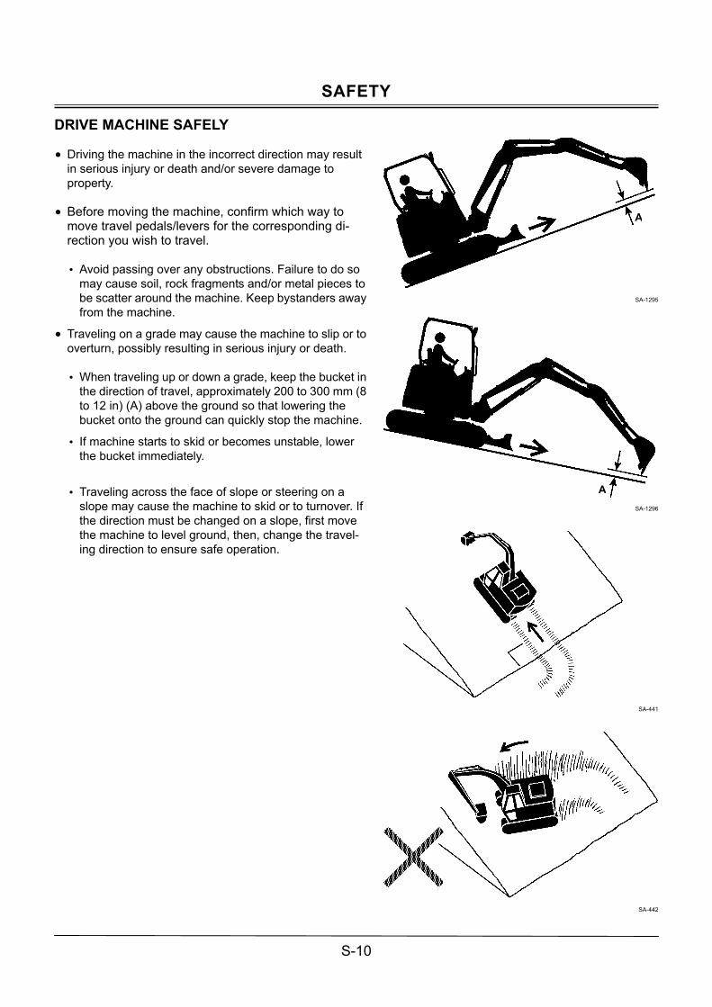
DRIVE MACHINE SAFELY
• Driving the machine in the incorrect direction may result in serious injury or death and/or severe damage to property.
• Before moving the machine, confirm which way to move travel pedals/levers for the corresponding di-rection you wish to travel.
� Avoid passing over any obstructions. Failure to do so
may cause soil, rock fragments and/or metal pieces to be scatter around the machine. Keep bystanders away from the machine.
• Traveling on a grade may cause the machine to slip or to overturn, possibly resulting in serious injury or death.
� When traveling up or down a grade, keep the bucket in
the direction of travel, approximately 200 to 300 mm (8 to 12 in) (A) above the ground so that lowering the bucket onto the ground can quickly stop the machine.
� If machine starts to skid or becomes unstable, lower the bucket immediately.
� Traveling across the face of slope or steering on a
slope may cause the machine to skid or to turnover. If the direction must be changed on a slope, first move the machine to level ground, then, change the travel-ing direction to ensure safe operation.
SA-1295
SA-1296
SA-441
SA-442
A
A
SAFETY
S-11
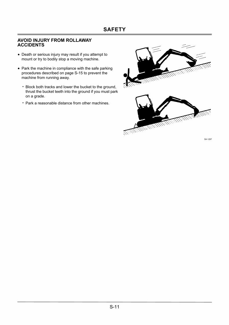
AVOID INJURY FROM ROLLAWAY ACCIDENTS
• Death or serious injury may result if you attempt to mount or try to bodily stop a moving machine.
• Park the machine in compliance with the safe parking procedures described on page S-15 to prevent the machine from running away.
� Block both tracks and lower the bucket to the ground,
thrust the bucket teeth into the ground if you must park on a grade.
� Park a reasonable distance from other machines.
SA-1297

SAFETY
S-12
AVOID INJURY FROM BACK-OVER AND SWING ACCIDENTS
• If any person is present near the machine when backing or swinging the upperstructure, the machine may hit or run over that person, resulting in serious injury or death.
To avoid back-over and swing accidents: � Always look around BEFORE YOU BACK UP AND
SWING THE MACHINE. BE SURE THAT ALL BYSTANDERS ARE CLEAR.
� Keep the travel alarm in working condition (if equipped). ALWAYS BE ALERT FOR BYSTANDERS MOVING INTO THE WORK AREA. USE THE HORN OR OTHER SIGNAL TO WARN BYSTANDERS BEFORE MOVING MACHINE.
� USE A SIGNAL PERSON WHEN BACKING UP IF YOUR VIEW IS OBSTRUCTED. ALWAYS KEEP THE SIGNAL PERSON IN VIEW. Use hand signals, which conform to your local regulations, when work conditions require a signal person.
� No machine motions shall be made unless signals are clearly understood by both signalman and operator.
� Learn the meanings of all flags, signs, and markings used on the job and confirm who has the responsibility for signaling.
� Keep windows, mirrors, and lights clean and in good condition.
� Dust, heavy rain, fog, etc., can reduce visibility. As visibility decreases, reduce speed and use proper lighting.
� Read and understand all operating instructions in the operator�s manual.
021-E01A-0494-8
SA-383
SA-384

SAFETY
S-13
KEEP PERSONNEL CLEAR FROM WORKING AREA
• If a person is present near the operating machine, the person may come in contact with the swinging front attachment or counterweight and/or may be crushed against an other object, resulting in serious injury or death.
� Before operating the machine, set up barriers to the
sides and rear area of the bucket swing radius to prevent anyone from entering the work area.
� Make sure that no personnel other than the signal person or no obstacles are present in the working area before operating the machine.
SA-667
NEVER POSITION BUCKET OVER ANYONE
• Never lift, move, or swing bucket above anyone or a truck cab. Serious injury or machine damage may result due to bucket load spill or due to collision with the bucket.
� Never allow the bucket to pass over anyone to avoid
personal injury or death.
SA-668
AVOID UNDERCUTTING
• In order to retreat from the edge of an excavation if the footing should collapse, always position the undercarriage perpendicular to the edge of the excavation with the travel motors at the rear.
� If the footing starts to collapse and if retreat is not
possible, do not panic raise the front attachment with a panic. Lowering the front attachment may be safer in most cases.
SA-1300

SAFETY
S-14
AVOID TIPPING
• The danger of tipping is always present when operating on a grade, possibly resulting in serious injury or death.
To avoid tipping:
• Be extra careful before operating on a grade. � Prepare machine operating area flat.
� Keep the bucket low to the ground and close to the machine.
� Reduce operating speeds to avoid tipping or slipping.
� Avoid changing direction when traveling on grades.
� NEVER attempt to travel across a grade steeper than 15 degrees if crossing the grade is unavoidable.
� Reduce swing speed as necessary when swinging loads.
• Be careful when working on frozen ground.
� Temperature increases will cause the ground to
become soft and make ground travel unstable.
025-E01A-0540-4
SA-1301
NEVER UNDERCUT A HIGH BANK
• The edges could collapse or a land slide could occur causing serious injury or death.
SA-1302
SAFETY
S-15
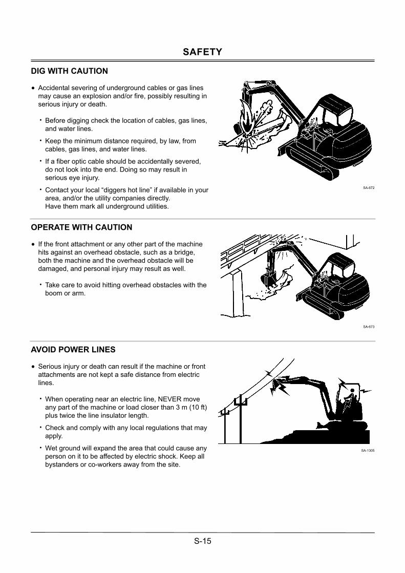
DIG WITH CAUTION
• Accidental severing of underground cables or gas lines may cause an explosion and/or fire, possibly resulting in serious injury or death.
� Before digging check the location of cables, gas lines,
and water lines.
� Keep the minimum distance required, by law, from cables, gas lines, and water lines.
� If a fiber optic cable should be accidentally severed, do not look into the end. Doing so may result in serious eye injury.
� Contact your local �diggers hot line� if available in your area, and/or the utility companies directly. Have them mark all underground utilities.
SA-672
OPERATE WITH CAUTION
• If the front attachment or any other part of the machine hits against an overhead obstacle, such as a bridge, both the machine and the overhead obstacle will be damaged, and personal injury may result as well.
� Take care to avoid hitting overhead obstacles with the
boom or arm.
SA-673
AVOID POWER LINES
• Serious injury or death can result if the machine or front attachments are not kept a safe distance from electric lines.
� When operating near an electric line, NEVER move
any part of the machine or load closer than 3 m (10 ft) plus twice the line insulator length.
� Check and comply with any local regulations that may apply.
� Wet ground will expand the area that could cause any person on it to be affected by electric shock. Keep all bystanders or co-workers away from the site.
SA-1305

SAFETY
S-16
DO NOT USE FOR CRANING OPERATIONS
• NEVER use the machine for craning operations. If the machine is used for craning operations, the machine may tip over and/or lifted load may fall, possibly resulting in serious injury or death.
• This machine has been exclusively designed to engage in excavation and loading works.
• This machine is not equipped with any of the necessary safety devices that could allow the machine to be used for craning operation.
SA-014
PROTECT AGAINST FLYING DEBRIS
• If flying debris such as soil, rock fragments or metal pieces hit eyes or any other part of the body, serious injury may result.
� Guard against such injuries when working in a job site
where possibility of flying pieces of metal or debris exist, or when removing or installing pins using a hammer; wear goggles or safety glasses.
� Keep bystanders away from the working area before striking any object.
SA-432
SAFETY
S-17
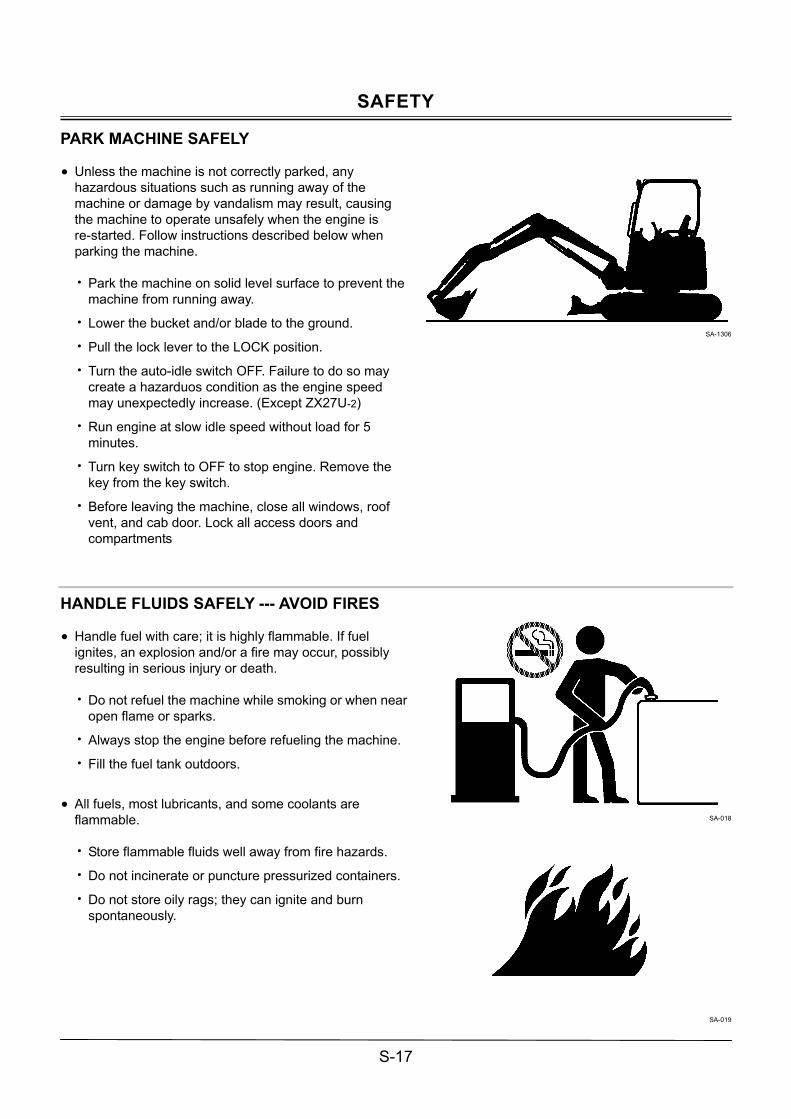
PARK MACHINE SAFELY
• Unless the machine is not correctly parked, any hazardous situations such as running away of the machine or damage by vandalism may result, causing the machine to operate unsafely when the engine is re-started. Follow instructions described below when parking the machine. � Park the machine on solid level surface to prevent the
machine from running away.
� Lower the bucket and/or blade to the ground.
� Pull the lock lever to the LOCK position.
� Turn the auto-idle switch OFF. Failure to do so may create a hazarduos condition as the engine speed may unexpectedly increase. (Except ZX27U-2)
� Run engine at slow idle speed without load for 5 minutes.
� Turn key switch to OFF to stop engine. Remove the key from the key switch.
� Before leaving the machine, close all windows, roof vent, and cab door. Lock all access doors and compartments
SA-1306
HANDLE FLUIDS SAFELY --- AVOID FIRES
• Handle fuel with care; it is highly flammable. If fuel ignites, an explosion and/or a fire may occur, possibly resulting in serious injury or death.
� Do not refuel the machine while smoking or when near
open flame or sparks.
� Always stop the engine before refueling the machine.
� Fill the fuel tank outdoors.
• All fuels, most lubricants, and some coolants are
flammable.
� Store flammable fluids well away from fire hazards.
� Do not incinerate or puncture pressurized containers.
� Do not store oily rags; they can ignite and burn spontaneously.
SA-018
SA-019

SAFETY
S-18
SAFETY TRANSPORTING
• The danger of tipping is present when loading/unloading the machine onto/from a truck or trailer bed.
� Be sure to observe local regulations when transporting
the machine on public roads.
� Provide an appropriate truck or trailer for transporting the machine.
� Be sure to have a signal person.
� Take the following precautions when loading/unloading the machine.
1. Select firm level ground.
2. Be sure to use a loading dock or ramp strong enough to support the machine weight.
3. Ramps must be sufficient in width, length, and strength. Be sure that the incline of the ramp is less than 15 degrees.
4. Loading docks must be sufficient in width and strength to support the machine and have a gradient of less than 15 degrees.
5. Be sure to turn the auto-idle switch (13) OFF. (Except ZX27U-2)
6. Slowly drive the machine.
7. Avoid steering while driving up or down the ramp as it is extremely dangerous. If steering is unavoidable, first move back to the ground or flatbed, modify traveling direction, and begin to drive again.
8. The top end of the ramp where it meets the flatbed is a sudden bump. Take care when traveling over it.
9. Wedge the front and rear of tracks. Securely fasten the machine to the trailer bed with chain or cables.
10. Do not operate any levers besides the travel levers when driving up or down the ramp.
11. Prevent possible injury from machine tipping while the upperstructure is rotating.
12. Keep the arm tucked under and rotate the upperstructure slowly for best stability.
Refer to "transporting" chapter in this manual for details
SA-1307
ZX27U-2
M1M7-01-031
ZX30U-2、ZX35U-2 ZX40U-2、ZX50U-2
M1M7-01-028
M1M7-01-033
M1M7-01-032
13
ZX27U-2 (Canopy)
ZX30U-2、ZX35U-2、ZX40U-2、ZX50U-2 (Canopy)

SAFETY
S-19
PRACTICE SAFE MAINTENANCE
• Inspection/maintenance work may produce hazardous situations by contacting and/or accessing a part of body to a moving, high pressure, and/or high temperature part of the machine. To avoid serious personal injury or death, follow the instructions described below.
� Thoroughly coordinate the working procedures to be taken hereafter with the co-workers before beginning work such as inspecting/servicing the machine, or replacing the attachiment .
� Safely park the machine in accordance with the instructions for �Park Machine Safely.�
� Keep the work area clean and orderly. � Attach a �DO NOT OPERATE� tag in an easy-to-see
location such as on a door or a control lever. � If moisture permeates into the electrical system,
malfunction and/or erroneous movement of the machine may result. Do not clean sensors, cable connectors, and the cab inside using water and/or steam.
� Wait to begin to work until the engine and hydraulic oil temperatures have cooled down to the safety range.
� In case inspection/maintenance must be performed with the engine runnning, be sure to appoint an overseer.
� Never lubricate or service the machine while moving it. � Repair the cracked windowpane before servicing the
machine. Failure to do so may cause personal injury. � Whe raising the machine above the ground using the
front attachment function, maintain the angle between the boom and the arm in the range of 90 to 110°. Never allow anyone to enter under the machine raised with the front attachment function.
� In case working under the machine raised above the ground is unavoidably required, securely hold the machine with stays or blocks strong enough to support the machine weight.
� Never work under the raised bucket. � Keep all parts in good condition and properly installed. � Always use the specified tools correctly. � Always use a clean tool. � Fix any damage found immediately. Replace worn or
broken parts. � Remove any buildup of grease, oil, or debris. � When cleaning parts, use a non-combustible cleaning
solvent. Never use an inflammable fluid such as dieasel fuel, or gasoline.
SA-028
M1M7-04-006
SA-527
90 to 110°

SAFETY
S-20
� Disconnect battery ground cable (−) before making adjustments to electrical systems or before welding on the machine.
� Sufficiently illuminate the work site. Use a maintenance work light when working under or inside the machine.
� Always use a work light protected with a guard. In case the light bulb is broken, spilled fuel, oil, antifreeze fluid, or window washer fluid may catch fire.
� When the floor tilt mechanism check and/or maintenance is conducted, the operator�s station is tilted upward. Before conducting maintenance work, refer to page 7-71 on this manual for the detailed operation procedures and correctly operate the machine.
� When required to work under the floor, securely support the floor opening section with wooden blocks to ensure safety.
� When the maintenance work is complete, the operator�s station is tilted downward. Slowly lower the operator�s station after removing the supporters such as wooden blocks.
� Failure to remove the supporters such as wooden blocks may damage the tilt mechanism.
SA-037
M1MH-07-013
WARN OTHERS OF SERVICE WORK
• Unexpected machine movement can cause serious injury.
� Before performing any work on the machine, attach a
�Do Not Operate� tag in an easy-to-see place such as on the cab door or control lever.
� Never attempt to operate the machine with a �Do Not Operate� tag attached.
� Make it a rule for the inspection/service person to hold the engine start key during inspection/service work.
SA-287

SAFETY
S-21
SUPPORT MACHINE PROPERLY
• Never attempt to work on the machine without securing the machine first.
� Always lower the attachment to the ground before you
work on the machine.
� If you must work on a lifted machine or attachment, securely support the machine or attachment with stays or blocks strong enough to support the machine and/or attachment weight.
SA-527
STAY CLEAR OF MOVING PARTS
• Contact with moving parts can cause serious injury or death due to amputation or entanglement.
� To prevent accidents, care should be taken to ensure
that hands, feet, clothing, jewelry and hair do not become entangled when working around rotating parts.
SA-026
PREVENT PARTS FROM FLYING
• Grease in the track adjuster is under high pressure. Failure to follow the precautions below may result in serious injury, blindness, or death.
� Do not attempt to remove GREASE FITTINGS or
VALVE ASSEMBLIES.
� As pieces of parts may fly off, be sure to keep body and face away from the valve.
• Travel reduction gears are under pressure.
� As pieces of parts may fly off, be sure to keep body and face away from AIR RELEASE PLUG to avoid injury.
� GEAR OIL is hot. Wait for gear oil to cool, then gradually loosen the air release plug to release pressure.
SA-344

SAFETY
S-22
STORE ATTACHMENTS SAFELY
• Stored attachments such as buckets, hydraulic hammers, and blades can fall and cause serious injury or death. � Securely store attachments and implements to prevent
falling accidents.
� Keep children and bystanders away from storage areas.
SA-034
PREVENT BURNS
Hot spraying fluids:
• After operation, engine coolant is hot and under pressure. Hot water or steam is contained in the engine, radiator and heater lines. Skin contact with escaping hot water or steam can cause severe burns. � To prevent possible injury from hot spraying water,
stop the engine. Begine to work after the engine and radiator are sufficiently cooled
� DO NOT remove the radiator cap until the engine is cool. When opening, turn the cap slowly to the stop. Allow all pressure to be release before removing the cap.
� The hydraulic oil tank is pressurized. Again, be sure to release all pressure by slowly removing the cap.
Hot fluids and surfaces:
• Engine oil, gear oil and hydraulic oil also becomes hot during operation. The engine, hoses, lines and other parts become hot as well.
� Wait for the oil and components to cool before starting
any maintenance or inspection work.
SA-039
SA-225

SAFETY
S-23
REPLACE RUBBER HOSES PERIODICALLY
• Rubber hoses that contain flammable fluids such as hydraulic oil or fuel under pressure may break due to aging, fatigue, and abrasion. It is very difficult to gauge the extent of deterioration due to aging, fatigue, and abrasion of rubber hoses by visual inspection alone.
� Periodically replace the rubber hoses.(Refer to the
Periodical Replacement Parts section.)
• Failure to periodically replace rubber hoses may cause a
fire, fluid injection into skin, or the front attachment to fall on a person nearby, which may result in severe burns, gangrene, or otherwise serious injury or death.
SA-019
AVOID HIGH-PRESSURE FLUIDS
• Fluids such as diesel fuel or hydraulic oil under pressure can penetrate the skin or eyes causing serious injury, blindness or death.
� Avoid this hazard by relieving pressure before
disconnecting hydraulic or other lines. Make sure that all connectors are completely connected before applying pressure.
� Search for leaks with a piece of cardboard; take care to protect hands and body from high-pressure fluids. Wear a face shield or goggles for eye protection.
� If an accident occurs, see a doctor familiar with this type of injury immediately. Any fluid injected into the skin must be surgically removed within a few hours or gangrene may result.
SA-031
SA-292
SA-044

SAFETY
S-24
PREVENT FIRES
Check for Oil Leaks:
• Fuel, hydraulic oil and lubricant leaks can lead to fires, possibly resulting in personal injury or death.
� Check for missing or loose clamps, kinked hoses,
lines or hoses that rub against each other, damage to the oil-cooler, and loose oil-cooler flange bolts, for oil leaks.
� Tighten, repair or replace any missing, loose or damaged clamps, lines, hoses, oil-cooler and oil-cooler flange bolts.
� Do not bend or strike high-pressure lines.
� Never install bent or damaged lines, pipes or hoses.
Check for Shorts:
• Short circuits can cause fires.
� Clean and tighten all electrical connections.
� Check before each shift or after eight (8) to ten (10) hours operation for loose, kinked, hardened or frayed electrical cables and wires.
� Check before each shift or after eight (8) to ten (10) hours operation for missing or damaged terminal caps.
� DO NOT OPERATE MACHINE if cable or wires are loose, kinked, etc.
SA-019

SAFETY
S-25
Precautions for Handling Flammables
• Spilled fuel and oil, and trash, grease, debris, accumulated coal dust, and other flammables may cause fires.
� Prevent fires by inspecting and cleaning the machine
daily, and by removing spilled or accumulated flammables immediately.
� Don�t store flammable fluid near open flames.
� Don�t burn or crush a pressurerized container.
� Don�t store oily cloths. They are liable to catch fire.
� Don�t wind easy-to-absorb-oil asbestos or glass wool around high-temperature parts such as a muffler or exhaust pipe.
Check Heat Shield Covers around Engine Compartment
• If the engine compartment heat shield cover becomes broken or lost, fire may break out.
� If the engine compartment heat shield cover becomes
broken or lost, repair or replace it before operating the machine.
Check Key Switch:
• If fire breaks out, failure to stop the engine will escalate the fire, hampering fire fighting.
� Always check key switch function before operating the
machine every day:
1) Start the engine and run it at slow idle.
2) Turn the key switch to the OFF position to confirm that the engine hasstopped.
If any abnormalities are found, be sure to repair them before operating the machine.

SAFETY
S-26
EVACUATING IN CASE OF FIRE
• If fire breaks out during machine operation, evacuate the machine in the following way:
� Stop the engine by turning the key switch to the OFF
position.
� Use a fire extinguisher if there is time.
� Exit the machine using handrails and/or steps.
� In an emergency, if the cab door or front window can not be opened, break the front or rear window panes with the emergency evacuation hammer to escape from the cab. Refer to the explanation pages on the Emergency Evacuation Method.
SA-393
(Cab-Equipped Machines)
SS4642980
BEWARE OF EXHAUST FUMES
• Prevent asphyxiation. Engine exhaust fumes can cause sickness or death.
� If you must operate the machine in a building, be sure
there is adequate ventilation. Either use an exhaust pipe extension to remove the exhaust fumes or open doors and windows to bring enough outside air into the area.
SA-016

SAFETY
S-27
PRECAUTIONS FOR WELDING AND GRINDING
• Welding may generate gas and/or small fires. � Be sure to perform welding in a well ventilated and
prepared area. Store flammable objects in a safe place before starting welding.
� Only qualified personnel should perform welding. Never allow an unqualified person to perform welding.
• Grinding on the machine may create a fire hazard. Store flammable objects in a safe place before starting grinding.
• After finishing welding and grinding, recheck that there are no abnormalities such as the area surrounding the welded area still smoldering.
SA-818
AVOID HEATING NEAR PRESSURIZED FLUID LINES
• Flammable spray can be generated by heating near pressurized fluid lines, resulting in severe burns to yourself and bystanders.
� Do not heat by welding, soldering, or using a torch
near pressurized fluid lines or other flammable materials.
� Pressurized lines can be accidentally cut when heat goes beyond the immediate flame area. Install temporary fire resistant guards to protect hoses or other materials before engaging in welding, soldering, etc.
AVOID APPLYING HEAT TO LINES CONTAINING FLAMMABLE FLUIDS
� Do not weld or flame cut pipes or tubes that contain flammable fluids.
� Remove flammable fluids thoroughly with nonflammable solvent before welding or flame cutting pipes or tubes that contained flammable fluids.
SA-030

SAFETY
S-28
REMOVE PAINT BEFORE WELDING OR HEATING
• Hazardous fumes can be generated when paint is heated by welding, soldering, or using a torch. If inhaled, these fumes may cause sickness. � Remove paint before welding or heating.
� Avoid potentially toxic fumes and dust.
� Do all such work outside or in a well-ventilated area. Dispose of paint and solvent properly.
� Allow fumes to disperse at least 15 minutes after welding or heating.
� Use attention to the following points when removing paint.
1. If you sand or grind paint, avoid breathing the dust which is created. Wear an approved respirator.
2. If you use solvent or paint stripper, remove stripper with soap and water before welding.
3. Remove solvent or paint stripper containers and other flammable material from area.
SA-029
PREVENT BATTERY EXPLOSIONS
• Battery gas can explode.
� Keep sparks, lighted matches, and flame away from the top of battery.
� Never check battery charge by placing a metal object across the posts. Use a voltmeter or hydrometer.
� Do not charge a frozen battery; it may explode. Warm the battery to 16 °C (60 °F) first.
� Do not continue to use or charge the battery when the electrolyte level is lower than specified. Explosion of the battery may result.
� When a terminal become loose, it may induce sparks. Securely tighten all terminals.
• Battery electrolyte is poisonous. If the battery should
explode battery electrolyte may be splashed into eyes, possibly resulting in blindness. If electrolyte is splashed into eyes, flush your eyes continuosly with water for about 15 minutes. Seek medical attention immediately.
� Be sure to wear eye protection when checking
electrolyte specific gravity.
SA-032

SAFETY
S-29
PRECAUTIONS FOR HANDLING REFRIGERANT
• If refrigerant is splashed into eyes or spilled onto skin, blindness or a cold contact burn may result.
� Refer to the precautions described on the refrigerant
container for handling refrigerant.
� Use a recovery and recycling system to avoid venting refrigerant into the atmosphere.
� Never allow the skin to directly come in contact with refrigerant.
SA-405
HANDLE CHEMICAL PRODUCTS SAFELY
• Direct exposure to hazardous chemicals can cause serious injury. Potentially hazardous chemicals used with your machine include such items as lubricants, electrolyte, coolants, paints, and adhesives.
� A Material Safety Data Sheet (MSDS) provides
specific details on chemical products: physical and health hazards, safety procedures, and emergency response techniques.
� Check the MSDS before you start any job using a hazardous chemical. Then follow the correct procedures and use recommended equipment.
� See your nearest Hitachi dealer for MSDS.
SA-309

SAFETY
S-30
DISPOSE OF WASTE PROPERLY
• Improperly disposing of waste can threaten the environment and ecology. Potentially harmful waste used with HITACHI equipment includes such items as oil, fuel, coolant, brake fluid, filters, and batteries.
� When draining fluid, use a leakproof container with a
capacity larger than the drained fluid volume to receive it.
� Do not pour waste onto the ground, down a drain, or into any water source.
� Inquire on the proper way to dispose of harmful waste such as oil, fuel, coolant, brake fluid, filters, and batteries from your local environmental or recycling center.
SA-226

SAFETY SIGNS
S-31
All safety signs and their locations affixed on the machine are illustrated in this group. Make sure of the contents described in the safety signs through reading actual ones affixed on the machine to ensure safe machine operation. Always keep the safety signs clean. In case a safety sign is broken or lost, immediately, obtain a new replacement and affix it again in position on the machine. Use the part No. indicated under the right corner of each safety sign illustration when placing an order of it to the Hitachi dealer.
SS3079466
SS-2640
SS4642518
M1M7-03-002

SAFETY SIGNS
S-32
SS-259
SS-2684
SS-2652
SS-024
SS-2639
SS3090482
M1M7-07-021
CANOPY
CAB

SAFETY SIGNS
S-33
SS3088058
SS-2651
M1M7-01-021
SS4433590
SS-2636
SS-2753
CAB
CANOPY
ZX30U-2、ZX35U-2、ZX40U-2、ZX50U-2
ZX27U-2

SAFETY SIGNS
S-34
SS4604981
SS-2685
SS4642517
SS-2685
SS4430516
SS-2686
SS-2687
ZX27U-2、ZX30U-2、ZX35U-2
ZX40U-2、ZX50U-2

SAFETY SIGNS
S-35
(Cab-Equipped Machines)
SS4642980
M1M7-01-020
(Cab-Equipped Machines)
SS-1832
M1M7-01-013
(2Way Multi Lever Equipped Machines)
SS4605065
SS-2640

SAFETY SIGNS
S-36
ROPS/TOPS/FOPS Canopy and Cab • To maintain unimpaired operator protection and
manufacture�s protective structure � Damaged Roll Over Protective Structure (ROPS),
Tip Over Protective Structure (TOPS), Falling Object Protective Structure (FOPS) must be replaced, not repaired or revised.
� Any alternation to the ROPS or TOPS or FOPS must be approved by the manufacturer.
SS3107469
SS3107610
ROPS/FOPS
SS3107593
SS-2651
CAB
SS-2652
CANOPY
ROPS/FOPS ROPS/FOPS

COMPONENTS NAME
1-1
COMPONENTS NAME
M1M7-01-001
1- Bucket
2- Arm
3- Bucket Cylinder
4- Arm Cylinder
5- Work Light
6- Boom
7- Boom Cylinder
8- Canopy
9- Track Shoe
10- Counterweight
11- Travel Device
12- Track Frame
13- Front Idler
14- Blade Cylinder
15- Blade
16- Boom-Swing Cylinder
8
9
10
11
14 12
16
1315
1
4
5 6
3 2
7

OPERATOR�S STATION
1-2
PEDALS, LEVERS AND MONITOR PANEL
1- Left Control Lever
2- Left Travel Lever
3- Right Travel Lever
4- Right Control Lever / Horn Switch
5- Blade Lever
6- Key Switch
7- Engine Control Dial (ZX30U-2, ZX35U-2, ZX40U-2, ZX50U-2)
Engine Control Lever (ZX27U-2)
8- Operator�s Seat
9- Boom Swing Pedal
10- Monitor Panel
11- Pilot Control Shut-Off Lever
12- Door Lock Release Lever (Cab equipped machine)
13- Switch Panel
14- Tool Box
15- Operator�s Manual Box
16- Attachment Pedal (Optional)
M1M7-01-034
M1M7-01-002
M1M7-01-003
2 3 4
10
8
11
1 9
5
7
13
15
14
12
16
6
ZX30U-2, ZX35U-2, ZX40U-2, ZX50U-2
2 3 41
9
5
7
6
ZX27U-2
10
13
8
16
15

OPERATOR�S STATION
1-3
17- Air Conditioner Control Panel (Cab equipped machine)
18- Ash Tray (Cab equipped machine)
19- Radio (AM/FM, Cab equipped machine)
20- Cup Holder
21- Fuse Box
M1M7-01-035
M1M7-01-004
M1LA-01-005
21
20 17 19
18
ZX30U-2, ZX35U-2, ZX40U-2, ZX50U-2
2019 18
17
ZX27U-2

OPERATOR�S STATION
1-4
KEY SWITCH
1- OFF (Engine OFF)
2- ON (Engine ON)
3- START (Engine Start)
4- HEAT (Engine Preheat)
SWITCH PANEL
5- Work Light Switch Press the top side of switch (5) to turn work lights (9) located on the boom and cab roof front ON. Press the bottom side of switch (5) to turn work lights (9) OFF.
6- Travel Mode Switch Press the rabbit-mark side of switch (6) to select the fast travel mode. However, when the travel load becomes heavy, the slow travel mode will automatically be selected. Press the turtle-mark side of switch (6) to select the slow travel mode.
7- Wiper Switch (Cab equipped machine) Three-operation positions are provided on this switch.
OFF: Both the wiper and washer do not operate.
Center: The wiper operates.
WASHER: The washer operates together with the wiper.
8- Auxiliary Flow Control Switch (Optional: Except ZX27U-2) The hydraulic oil flow in the auxiliary pipe line can be controlled.
M1M7-01-025
M1M7-01-007
M1M7-01-033
M1M7-05-026
M1M7-01-036
M1M7-01-024
6 5
5 6 7 8
ZX30U-2, ZX35U-2, ZX40U-2, ZX50U-2 (Cab)
ZX30U-2, ZX35U-2, ZX40U-2, ZX50U-2 (Canopy)
3
2
1
4
8
9
6 5
ZX27U-2 (Canopy)
6
ZX27U-2 (Cab)
5 7

OPERATOR�S STATION
1-5
MONITOR PANEL
1- Coolant Temperature Gauge
2- Fuel Gauge
3- Liquid Crystal Display (Hour Meter, etc)
4- Set Switch
5- Display Control Switch
6- Auto-Idle Indicator (Except ZX27U-2)
7- Auto-Idle Switch (Except ZX27U-2)
8- Fast Travel Mode Indicator
9- Preheat Indicator
10- Alternator Indicator
11- Fuel Level Indicator
12- Overheat Indicator
13- Engine Oil Pressure Indicator
14- System Failure Indicator
Coolant Temperature Gauge
The gauge segment position indicates the engine coolant temperature. When the first three segments come ON, the coolant temperature is normal.
NOTE: When the coolant temperature is lower than 20°C, the first segment will flash.
Fuel Gauge
The gauge segment position indicates the fuel level. Refill the fuel before only the E-marked segment comes ON.
NOTE: Even though the key switch is OFF, when the display control switch is continuously pressed for more than 0.5 seconds, the fuel level is displayed. As long as the display control switch is kept pressed, the gauge indicates the fuel level. When the switch is released, the gauge stops indication the fuel level.
IMPORTANT: In case all segments flash, the machine is abnormal. Immediately, contact your nearest Hitachi dealer.
M1M7-01-031
M1M7-01-028
M1SM-05-008
M1SM-01-003
1 2
34
56
7
8
16
15
14
13
12
11
10
9
1 2
3
4
516
15
14
13
12
11
10
ZX27U-2
ZX30U-2, ZX35U-2, ZX40U-2, ZX50U-2

OPERATOR�S STATION
1-6
System Failure Indicator
The system failure indicator comes ON or flashes an abnormality may be present in the engine control system (optional: Except ZX27U-2). If the system failure indicator comes ON or flashes, immediately contact your nearest Hitachi dealer for repair.
Engine Oil Pressure Indicator
The red indicator will light when the engine oil pressure is low. If the red indicator comes ON, the engine oil pressure warning buzzer will sound at the same time. Immediately stop the engine. Check the engine oil pressure system and the oil level for any abnormality. Overheat Indicator
If the coolant temperature rises extremely high, this indicator operates. If the red light comes ON, the buzzer sounds at the same time. Immediately stop machine operation and reduce engine speed to the slow idle speed to lower the coolant temperature. Fuel Level Indicator
When the fuel level indicator comes ON while the machine is operating on level ground, the remaining fuel amount in the fuel tank is as shown in the table below. Refill the fuel as soon as possible.
Model Remaining Fuel Amount ZX27U-2, ZX30U-2, ZX35U-2 6.5 litters ZX40U-2, ZX50U-2 11 litters
M1M7-01-008
M178-01-037
M178-01-036
M178-01-034

OPERATOR�S STATION
1-7
Alternator Indicator
The red indicator will light when low alternator output is present. Check the electrical system such as the alternator and/or battery system. Preheat Indicator
When the key switch is turned to the HEAT position, orange indicator will light. Light will turn off after approx. 15 seconds has passed. Fast Travel Mode Indicator
When the rabbit-mark (fast mode) side of the travel mode switch on the switch panel is pressed, the indicator comes ON.
M178-01-038
M178-01-041
M1M7-01-022

OPERATOR�S STATION
1-8
LIQUID CRYSTAL DISPLAY (LCD), DISPLAY SELECTION SWITCH, AND SET SWITCH
LCD (3) indicates 3 types of meters, Hour Meter, Trip Meter 1 or Trip Meter 2.
NOTE: After the key switch is turned ON, LCD always indicates the hour meter.
• How to Select Display
Each time display control switch (5) is pressed, LCD alternately displays Hour Meter, Trip Meter 1, and Trip meter 2 in this order.
• Hour Meter Display The hour meter displays the total accumulated machine operation hours in hour (h) units since the machine started operation. One digit beyond the decimal point indicates tenths of an hour (six minutes). When the hour meter is displayed, the hour meter mark is lit. While the machine is operating, the decimal point flashes.
NOTE: Even though the key switch is OFF, the hour meter reading can be checked by depressing and holding display selection switch (5) for more than 0.5 seconds. The hour meter reading can be displayed as long as display selection switch (5) is held and disappears as soon as the switch is released.
• Trip Meter Display (Trip Meter 1 and Trip Meter 2)
The remaining hours until the trip mark flashes from the set-hours are indicated in hour (h) unit. (See page 1-9.) As long as the trip meter is displayed, trip mark (TRIP 1 or TRIP 2) lights on the screen.
M1M7-01-031
M1M7-01-028
M1SM-01-005
M1SM-01-006
M1SM-01-007
When the hour meter is displayed
Hour Meter Mark
When Trip meter 2 is displayed
When Trip meter 1 is displayed
Trip Mark
Hour Meter Mark
Hour Meter Mark
Trip Mark
3
5
3
5
ZX27U-2
ZX30U-2, ZX35U-2, ZX40U-2, ZX50U-2

OPERATOR�S STATION
1-9
HOW TO OPERATE TRIP METER
• Trip Meter Function The trip meter flashes the trip mark (TRIP 1 or TRIP 2) to inform the operator that the machine operation hours have reached the preset hour. The trip mark continues to flash for 30 seconds when the machine operation hours reach the preset hours. Unless the trip meter is reset, each time when the key switch is turned ON, the trip mark repeatedly flashes for 30 seconds.
IMPORTANT: The trip meter indicates the machine
operation hours which are counted from the time when the trip meter is set. Therefore, the machine operation hours indicated by the trip meter are different from the accumulated operation hours indicated by the hour meter.
NOTE: Once the trip meter has been set, its function is kept activated even though other types of information is displayed on the LCD afterward. Therefore, when the operation hours reach the preset hours in the trip meter, the trip mark will start flashing regardless of the current LCD operation status. If the trip mark starts flashing when the trip meter is being indicated, the trip mark will stay ON after trip mark stops flashing. In case information other than the trip meter is being indicated on the LCD, the trip mark will be extinguished after the flashing ceases.
• Trip Meter Setting
1. Turn the key switch ON. Display either trip meter 1 or trip meter 2 by operating display selection switch (5).
NOTE: Trip meter 1 and trip meter 2 can be independently set by different operation hours.
2. Each time set switch (4) is pressed, the set-hour is shifted in the following order: 50>100>150>200>250>300>400>500>750>1000>1250>1500>2000>2500>3000 Select the desired time to set by operating set switch (4). When the set switch is pressed for more than 2 seconds, the set-hour will be quickly shifted.
3. While displaying the desired time to be set, press display selection switch (5) to set the trip meter.
NOTE: When either trip meter 1 or 2 is set and is kept displayed on the LCD, the remaining operation hours of the machine are displayed on the LCD until the operation hours reach the set-hour. Accordingly, when the trip mark starts flashing, the trip meter displays 0 hour. Then the trip meter will continue to display the operation overtime from the set-hour with minus (-) mark until the trip meter is reset.
M1M7-01-031
M1M7-01-028
M1SM-01-006
M1SM-01-007
When Trip meter 2 is displayed
When Trip meter 1 is displayed
Trip Mark
34
5
3
4
5
ZX27U-2
ZX30U-2, ZX35U-2, ZX40U-2, ZX50U-2
Trip Mark
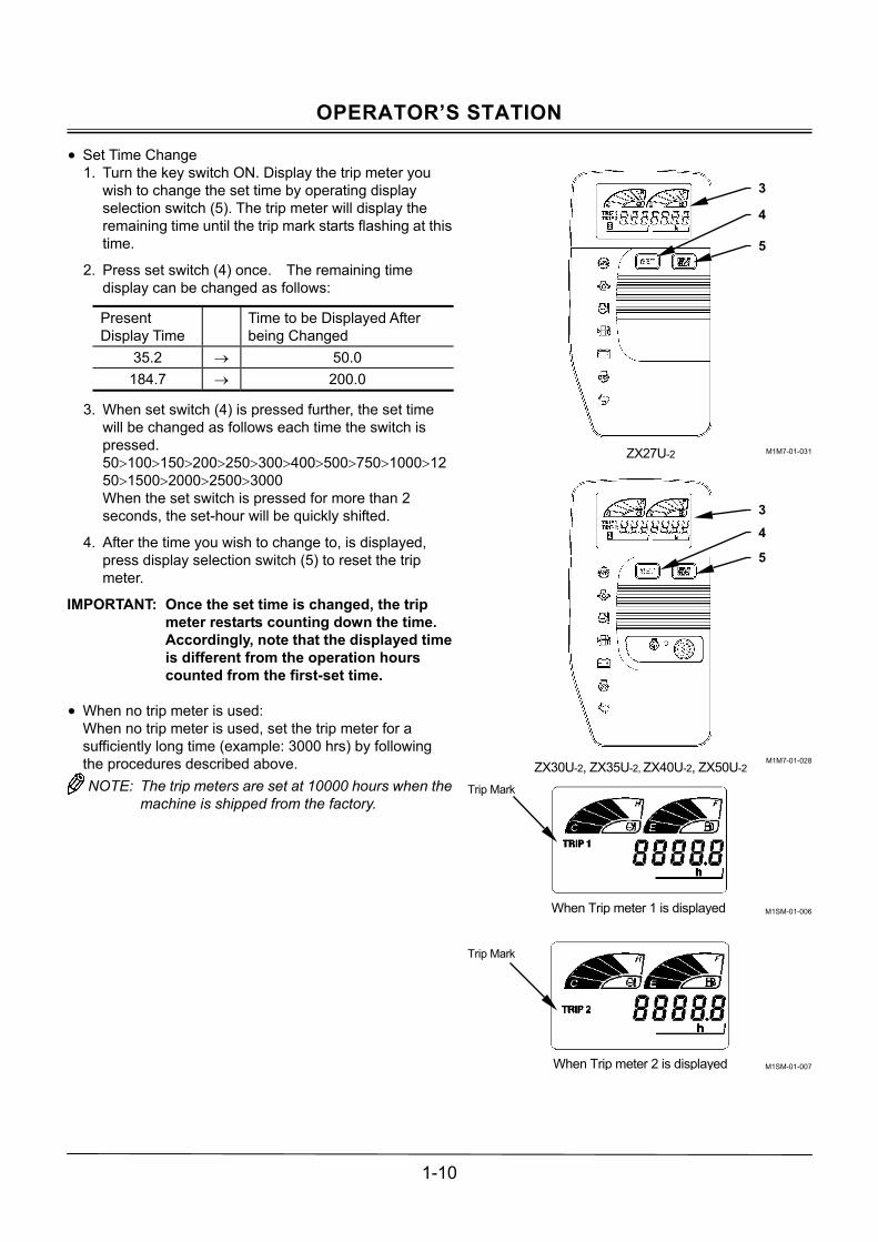
OPERATOR�S STATION
1-10
• Set Time Change 1. Turn the key switch ON. Display the trip meter you
wish to change the set time by operating display selection switch (5). The trip meter will display the remaining time until the trip mark starts flashing at this time.
2. Press set switch (4) once. The remaining time display can be changed as follows:
Present Display Time
Time to be Displayed After being Changed
35.2 → 50.0 184.7 → 200.0
3. When set switch (4) is pressed further, the set time will be changed as follows each time the switch is pressed. 50>100>150>200>250>300>400>500>750>1000>1250>1500>2000>2500>3000 When the set switch is pressed for more than 2 seconds, the set-hour will be quickly shifted.
4. After the time you wish to change to, is displayed, press display selection switch (5) to reset the trip meter.
IMPORTANT: Once the set time is changed, the trip meter restarts counting down the time. Accordingly, note that the displayed time is different from the operation hours counted from the first-set time.
• When no trip meter is used:
When no trip meter is used, set the trip meter for a sufficiently long time (example: 3000 hrs) by following the procedures described above. NOTE: The trip meters are set at 10000 hours when the
machine is shipped from the factory.
M1M7-01-031
M1M7-01-028
M1SM-01-006
M1SM-01-007
When Trip meter 2 is displayed
When Trip meter 1 is displayed
Trip Mark
34
5
3
4
5
ZX27U-2
ZX30U-2, ZX35U-2, ZX40U-2, ZX50U-2
Trip Mark

OPERATOR�S STATION
1-11
Auto-Idle Mode Switch (Except ZX27U-2)
• Auto-Idle Operation When auto-idle mode switch (13) is turned to the Auto-Idle position, the engine speed is reduced to the slow idle speed approx. 4 seconds after returning all control levers to neutral. Thereby, the fuel consumption is reduced. When the auto-idle mode is selected, auto-idle indicator (14) on the monitor panel lights.
M1CF-01-002
M1M7-01-028
14
13

OPERATOR�S STATION
1-12
AIR CONDITIONER OPERATION
1- Control Panel
2- Right Front Air Vent 1
3- Right Front Air Vent 2
4- Foot Air Vent
NOTE: Control air-flow from right front air vents (1 and
2) by rotating the louver in the horizontal direc-tion so that the air vents can be used as a de-froster.
5- Air Conditioner Power Switch
Press air conditioner power switch (5) to turn the power ON.
Controller Part Names and Functions
6- Air Conditioner Switch Press air conditioner switch (6) to turn the air condi-tioner ON. The A/C indicator lights up.
7- Vent Mode Switch The air vent can be selected as shown below:
Air will bow out from right front vents 1(2) and 2(3)
Air will bow out from right front vents 1(2) and 2(3), and the foot vent (4).
Air will bow out from the foot vent (4).
8- Temperature Control Switch
The set temperature decreases each time the switch with ← mark is pressed, and increases each time the switch with → mark is pressed.
9- Blower Switch The blower speed can be adjusted in 3 stages from Slow, Medium, and Fast.
M1M7-01-004
M1M7-01-009
M1M7-01-010
1
2
3
4
6 7 8 9 5

OPERATOR�S STATION
1-13
Heating Operation
Although warm air will blow out from all three vents, normally the foot vent is used for heating operation. After selecting the foot vent by operating vent mode switch (7), press temperature control switch (8) to set the tempera-ture indicator toward the right end side. Adjust the inside cab temperature using temperature control switch (8). The blower speed can be adjusted manually using blower switch (9). When air conditioner switch (6) is turned ON during heating operation, air in the cab will be dehumidified.
Cooling Operation
Although cool air will blow out from all three vents, nor-mally the foot vent is used for cooling operation. After selecting the foot vent by operating vent mode switch (7), press temperature control switch (8) to set the tempera-ture indicator toward the left end side. Adjust the inside cab temperature using temperature control switch (8). The blower speed can be adjusted manually using blower switch (9). When air conditioner switch (6) is turned ON during cooling operation, cool air will also blow out from the right front vent.
Defroster Operation
Select the right front vents by operating vent mode switch (7). Adjust the louvers on right front vents 1 and 2 as required. The blower speed can be adjusted manually using blower switch (9). Adjust the inside cab tempera-ture using temperature control switch (8). Turn air condi-tioner switch (6) ON if the windows become clouded, or if dehumidifying in the cab is required.
M1M7-01-010
M1M7-01-010
M1M7-01-009
6 7 8 9 5
6 7 8 9 5
2
3
4

OPERATOR�S STATION
1-14
TIPS FOR AIR CONDITIONER USAGE
Rapid Cooling
Temperature in the cab may rise over 80°C when the machine is exposed to direct sunlight with the cab win-dows closed. Under this condition, in case temperature in the cab is required to be rapidly cooled, ventilate air from the cab first by opening the windows. After starting the engine, set the temperature control toward the far left end using temperature control switch (8). Select the right front vent mode. Run the blower at the slow speed posi-tion. Turn air conditioner switch (6) ON. After keep the engine running at slightly faster speed (over 1000 min-1[rpm]) for a few minutes, increase the blower speed. When the air temperature in the cab is decreased to the atmosphere temperature, close the windows. If Windows Become Clouded
The windows will become cloudy if the humidity in the cab become high. Operate the air conditioner to keep the windows clear. When the atmosphere is very damp, the outside of the windows may become clouded if the air conditioner is operated for long periods. In this case, stop the air conditioner and/or adjust the air temperature in the cab. When the air conditioner is not used
When the air conditioner is not used, to protect each part of the compressor from a lack of lubricant, operate the air conditioner at least once a month for several minutes with the engine running at a slow speed. When the cab temperature is lower than 15°C, the air conditioner may not operate. In this case, warm the cab inside using the heater first to increase the cab temperature.
IMPORTANT: � Do not suddenly increase the engine speed,
failure to do so possibly result in damage to the compressor.
� Keep fire hazards away from the control panel.
� Refer to the descriptions in Clean/Replace Air Conditioner Filter in the Maintenance Section for the maintenance of the air conditioner fil-ters.
M1M7-01-010
6 7 8 9 5

OPERATOR�S STATION
1-15
RADIO (Cab Equipped Machines)
1- Radio/Clock
M1M7-01-004
1

OPERATOR�S STATION
1-16
AM/FM RADIO OPERATION
Part Name and Function
1- Power Switch/Volume Control Knob Rotate the knob to the right to supply electric power (a click sound will be heard when the unit is turned ON). Rotate the knob further to turn up the volume. Rotate the knob in the reverse direction to turn down the volume and the unit OFF.
2- Tone Control Knob Rotate the knob to the right to intensify the treble. Rotate the knob to the left to reduce the treble.
3- Display Time, receiving radio wave frequency, or operation mode is displayed.
4- Clock Button Press this button to display the time. Repress this button to display the receiving radio wave frequency.
5- Auto-Store/ Scan Preset Button (AST) Press this button to receive the preset frequency station for every 5 seconds sequentially. While you receive the station you wish to listen to, press this button again to receive the station under normal state (scan is interrupted). Press and hold this button for 2 seconds to automatically store the station.
6- Station Preset Buttons (1 to 6) One FM and MW (AM) station per button can be preset using these respective buttons.
7- Seek Button Press this button to automatically seek the next re-ceivable station. When a station is received, the auto-seeking function is deactivated.
8- Band Button Select FM or MW (AM) by pressing this button. The display indicates the receiving station frequency.
9- Tuning Button Tap the TUNE ∧ button to increase the frequency. Tap the TUNE ∨ button to decrease the frequency. Tap and hold the button to change the frequency continuously.
Radio Operation
1. Turn the key switch to the ACC or ON position to switch the radio ON.
2. Select either MW (AM) or FM by operating the brand button.
3. Select the station desired to listen using the preset or tuning button.
4. Adjust the volume and tone according to your pref-erence.
5. When turning the radio OFF, rotate the VOL knob to the left until a click sound is heard.
M1M7-01-011
2 6 9
1 3 8 5 7 4

OPERATOR�S STATION
1-17
Tuning Procedure
1. Tap the TUNE ∧ button to increase the frequency. Tap the TUNE ∨ button to decrease the frequency. Tap and hold the button to change the frequency con-tinuously.
2. Automatic Tuning Press this button to automatically move the frequency up and to seek a receivable station. When a station is received, the auto-seeking function is deactivated so that the received frequency station is tuned in.
Station Presetting Procedure
1. Select MW(AM) or FM by pressing BAND button (8). Select a station by pressing either TUNE button (9) or SEEK button (7).
2. Continuously press one of PRESET button (6) by which you desire to preset the station for more than 2 seconds. When presetting is complete, the preset button No. is indicated on the display.
3. Repeat the above same procedure steps (1) and (2) to preset other stations with other PRESET buttons (6).
NOTE: After presetting is complete, if the preset button is pressed again and held for more than 2 seconds, the preset station is changed.
� Auto-Storing Press and hold the AST button for more than 2 sec-onds with the radio switch ON, preset buttons (1 to 6) automatically search receivable frequency stations in the selected frequency band (AM or FM) and memo-rize each station in one button.
NOTE: When auto-store operation is made, the pre-ciously memorized stations are deleted. If it is difficult to set the memory of the desired station to the desired button, conduct preset operation.
� Preset Scanning
Press and release the AST button in 2 seconds with the radio switch ON, preset station frequencies are received one by one for 5 seconds. Press the button again to resume normal radio operation.
Deletion of Preset Memory
If the battery power is disconnected such as when the machine is serviced or the radio is removed, the preset memory in the preset buttons will be deleted. Repeat the preset operation again.
M1M7-01-011
M1M7-01-011
2 6 9
1 3 8 5 7 4
2 6 9
1 3 8 5 7 4

OPERATOR�S STATION
1-18
Clock Setting Procedure
In case the frequency is indicated on the display, press the CLOCK button to display the time. While pressing the CLOCK button, press TUNE∧M but-ton to change the minute display. While pressing the CLOCK button, press TUNE∨H button to change the hour display. Release the CLOCK button to resume the original mode.
CAB DOOR RELEASE LEVER (Only on cab-equipped machines)
CAUTION: Open the cab door all the way until the two latches on the side of the cab securely lock.
To unlock the door, push down on lever (1) located on the left side of the operator’s seat.
M1M7-01-012
M1M7-01-003
M1M7-01-027
While pressing CLOCK button
Minute is adjusted
Hour is adjusted
1
Second LatchFirst Latch

OPERATOR�S STATION
1-19
OPENING/CLOSING CAB FRONT WINDOW (Only on cab-equipped machines)
Front Window
1. Disengage lock lever (1) provided at the upper right and left corner of the front window.
2. Hold the handles (in two places) on the front window frame and raise the window until the lock lever en-gages with the window frame.
CAUTION: � When closing the front window, slowly lower
the window. Be alert not to pinch your fingers.
� Switch (2) is provided on the front window frame to prevent the wiper from operating when the front window is opened. Before closing the front window, check that the wiper switch is OFF.
� After opening the front window, check that both side lock levers are securely engaged in the window frame.
3. When closing the front window, follow the same steps 1 and 2 above in the reverse order.
M1M7-01-013
M1M7-01-014
M1M7-01-015
1
1 1
2
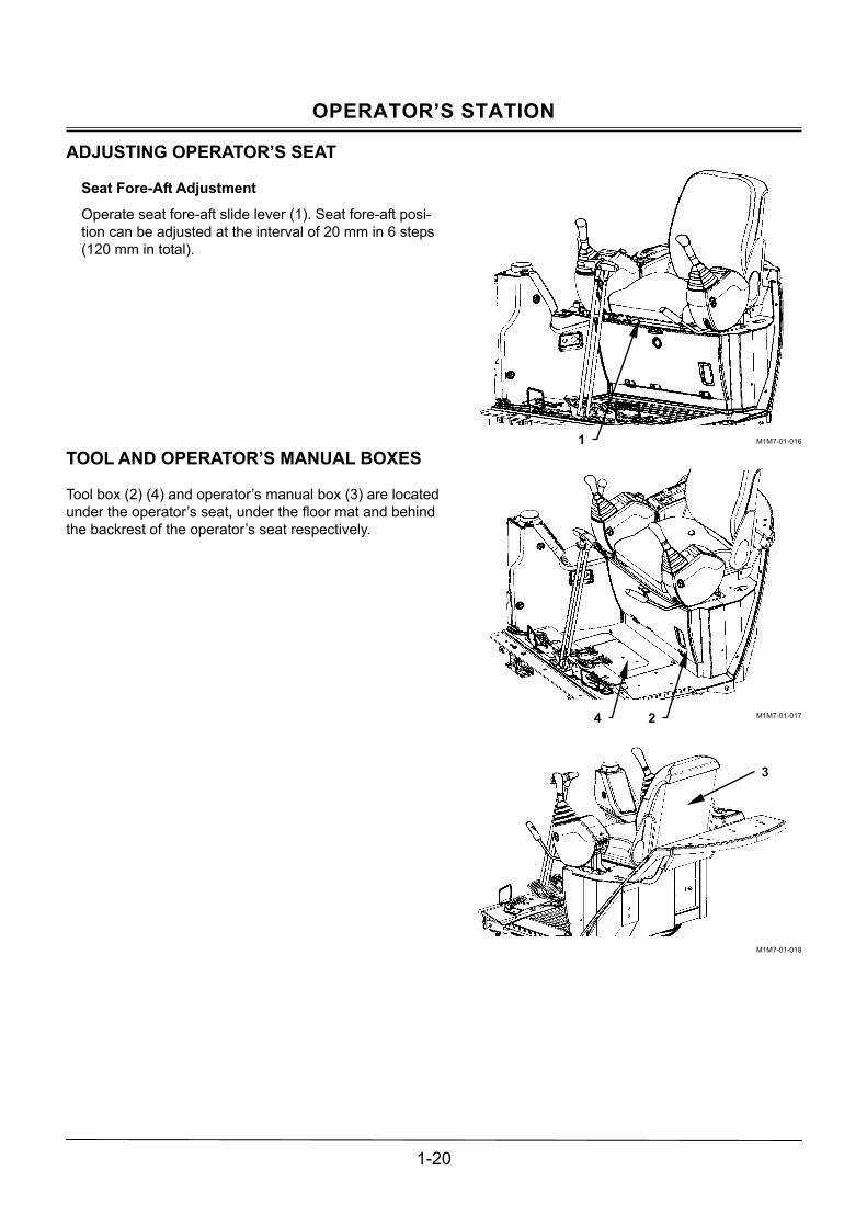
OPERATOR�S STATION
1-20
ADJUSTING OPERATOR�S SEAT
Seat Fore-Aft Adjustment Operate seat fore-aft slide lever (1). Seat fore-aft posi-tion can be adjusted at the interval of 20 mm in 6 steps (120 mm in total).
TOOL AND OPERATOR�S MANUAL BOXES
Tool box (2) (4) and operator�s manual box (3) are located under the operator�s seat, under the floor mat and behind the backrest of the operator�s seat respectively.
M1M7-01-016
M1M7-01-017
M1M7-01-018
1
4 2
3

OPERATOR�S STATION
1-21
OPENING/CLOSING CAB REAR WINDOW (cab-equipped machines)
CAUTION: Normally use the rear widow to ven-tilate the cab in the operation range of lock (1). Don�t operate the machine with screws (2) re-moved from the cab rear window. Screws (2) are to be removed to open/close the rear window only in an emergency.
After detaching locks (1), push the widow outward.
M1M7-01-019
2
1

OPERATOR�S STATION
1-22
EMERGENCY EXIT (cab-equipped machines)
If the operator�s cab door can not be opened in an emer-gency, escape in the following methods.
1. When required to escape from the cab when the door is difficult or impossible to open in an emergency, open the front window.
NOTE: Refer to the descriptions in OPEN-ING/CLOSING CAB FRONT WINDOW for the opening method of the front window.
CAUTION: Be sure to wear safety glasses when require to break the windowpane.
2. In case opening the front window is impossible, break
the front window glass with emergency evacuation hammer (1) provided on the rear side in the cab to escape through the broken window.
3. If the front window is not available for escaping, break
the rear window glass with emergency evacuation hammer (1). Then, escape through the broken win-dow.
NOTE: Emergency exit decal is affixed on the front and left rear window.
M1M7-01-020
M1M7-01-037
M1M7-01-038
1
Front
Rear

OPERATOR�S STATION
1-23
SEAT BELT (OPTIONAL)
CAUTION: Be sure to use the seat belt when op-erating the machine. Before operating the machine, be sure to examine seat belt (1), buckle (2), or attaching hardware. Replace seat belt (1), buckle (2), or attaching hardware if they are damaged, or worn. Replace seat belt (1) every three years, regard-less of appearance.
Seat Belt
1. Confirm that seat belt (1) is not twisted and securely insert the end of seat belt (1) into buckle (2). Lightly pull on the belt to confirm that the buckle latches securely.
2. Adjust tightness of the seat belt (1) so that the belt is snug but comfortable.
3. Push button (3) on buckle (2) to unfasten seat belt (1).
CAB LIGHT (cab-equipped machines)
Move cab light switch (4) to turn the cab light ON or OFF. (The cab light comes ON only when the key switch is turned ON.)
M573-01-014
M107-01-045
M573-01-015
M1M7-01-021
1
2 1
2 1
3
4

OPERATOR�S STATION
1-24
MEMO
.....................................................................................................................................................................................
.....................................................................................................................................................................................
.....................................................................................................................................................................................
.....................................................................................................................................................................................
.....................................................................................................................................................................................
.....................................................................................................................................................................................
.....................................................................................................................................................................................
.....................................................................................................................................................................................
.....................................................................................................................................................................................
.....................................................................................................................................................................................
.....................................................................................................................................................................................
.....................................................................................................................................................................................
.....................................................................................................................................................................................
.....................................................................................................................................................................................
.....................................................................................................................................................................................
.....................................................................................................................................................................................
.....................................................................................................................................................................................
.....................................................................................................................................................................................
.....................................................................................................................................................................................
.....................................................................................................................................................................................
.....................................................................................................................................................................................
.....................................................................................................................................................................................
.....................................................................................................................................................................................
.....................................................................................................................................................................................
.....................................................................................................................................................................................
.....................................................................................................................................................................................
.....................................................................................................................................................................................
.....................................................................................................................................................................................
.....................................................................................................................................................................................

BREAK-IN
2-1
BREAKING IN NEW MACHINE
IMPORTANT: Operating a new machine at full load without first breaking in can cause scratches and/or seizures, consequently affecting the service life of the machine. Thoroughly perform break-in operation.
The service life and performance of the machine can be greatly affected by operation and maintenance of the ma-chine during the initial stage of operation. Perform break-in operation with the engine output less than 80% of the maximum output for the first 50 hours.

BREAK-IN
2-2
MEMO
.....................................................................................................................................................................................
.....................................................................................................................................................................................
.....................................................................................................................................................................................
.....................................................................................................................................................................................
.....................................................................................................................................................................................
.....................................................................................................................................................................................
.....................................................................................................................................................................................
.....................................................................................................................................................................................
.....................................................................................................................................................................................
.....................................................................................................................................................................................
.....................................................................................................................................................................................
.....................................................................................................................................................................................
.....................................................................................................................................................................................
.....................................................................................................................................................................................
.....................................................................................................................................................................................
.....................................................................................................................................................................................
.....................................................................................................................................................................................
.....................................................................................................................................................................................
.....................................................................................................................................................................................
.....................................................................................................................................................................................
.....................................................................................................................................................................................
.....................................................................................................................................................................................
.....................................................................................................................................................................................
.....................................................................................................................................................................................
.....................................................................................................................................................................................
.....................................................................................................................................................................................
.....................................................................................................................................................................................
.....................................................................................................................................................................................
.....................................................................................................................................................................................

OPERATING ENGINE
3-1
BEFORE STARTING ENGINE
1. Check that pilot control shut-off lever (1) in the LOCK position.
2. Confirm that all control levers are placed in neutral.
3. Check indicator bulbs as follows: Turn key switch to the ON position. All indicator lights and warning lamps will come on. They will stay on for approximately 3 seconds, except for alternator (3) and engine oil pressure (4) indicator, which will con-tinue to stay on further.
IMPORTANT: The monitor panel indicates the machine operating conditions. If the machine is operated with an indicator bulb or a warning lamp burned out, the alarm will not be displayed even if any abnormality occurs on the machine. Accordingly, in case any of the indicator bulbs or the warning lamps doesn�t come ON, imme-diately contact your nearest Hitachi dealer for repair. If any of alternator (3), engine oil pressure (4), or system failure indicator (5) (Except ZX27U-2) fails to light after indicator light check is com-pleted, the machine may have trouble. Immediately contact your nearest Hitachi dealer for repair.
4. Adjust the seat position so that all pedals and control
levers can be fully stroked to any position when seated in the operator�s seat with the operator�s back kept in contact with the backrest. Fasten the seat belt.
NOTE: The monitor surfaces are resin. Wipe the sur-face only with a damp cloth when dusty to keep them clean. Never use an organic solvent.
M1M7-03-001
M1M7-01-007
ZX27U-2
M1M7-01-031
ZX30U-2, ZX35U-2 ZX40U-2, ZX50U-2
M1M7-01-028
2
1
5
4
3
5
4
3

OPERATING ENGINE
3-2
STARTING ENGINE
Starting in Ordinary Temperature
1. Check that pilot control shut-off lever (1) in the LOCK position.
2. Turn engine control dial or engine control lever (3) to the slow idle position.
3. Sound the horn to alert bystanders.
4. Turn key switch (2) to rotate the starter. The engine will be started.
IMPORTANT: Prevent starter damage and/or battery over discharge. Never run the starter for more than 20 seconds at a time. If the engine fails to start, return the key switch to OFF. Wait for more than 30 seconds, then try again.
5. Release key switch (2) immediately after the engine
has started. It will automatically return to the ON po-sition.
NOTE: The horn sounds even though the key switch is turned OFF. The engine doesn�t start unless the pilot control shut-off lever is in the LOCK posi-tion.
IMPORTANT: Avoid operating key switch (2) with
stained hands or gloves.
M1M7-03-001
M1M7-03-006
M1M7-03-002
M1M7-01-007
2
1
3
ZX30U-2, ZX35U-2, ZX40U-2, ZX50U-2
3
ZX27U-2

OPERATING ENGINE
3-3
STARTING IN COLD WEATHER
1. Check that pilot control shut-off lever (1) is in the LOCK position.
2. Turn engine control dial or engine control lever (3) to around the middle between the slow and fast idle po-sitions.
3. Turn key switch (2) to the HEAT position and hold it in that position for approx. 15 seconds until preheat in-dicator (4) goes OFF.
4. Sound the horn to alert bystanders.
5. As soon as preheat indicator (4) goes OFF, return key switch (2) to the START position to run the starter.
IMPORTANT: Prevent starter damage and/or battery over discharge. Never run the starter for more than 20 seconds at a time. If the engine fails to start, return the key switch to OFF. Wait for more than 30 seconds, then try again.
6. Release key switch (2) immediately after the engine
has started. It will automatically return to the ON po-sition.
NOTE: Set the engine control dial or lever to the fast idle position to start the engine in an extreme cold weather district. After the engine is started, gradually reduce the engine speed and perform warm-up operation at the medium speed range.
M1M7-01-007
M1M7-03-001
M1M7-03-006
M1M7-03-002
ZX27U-2
M1M7-01-031
ZX30U-2, ZX35U-2 ZX40U-2, ZX50U-2
M1M7-01-028
1
2
3
ZX30U-2, ZX35U-2, ZX40U-2, ZX50U-2
4 4
3
ZX27U-2

OPERATING ENGINE
3-4
CHECK MACHINE AFTER STARTING ENGINE
IMPORTANT: In case any abnormality is found in the monitor, immediately stop the engine. Trace the cause of the problem.
Check Using the Monitor
After the engine has started, check the following points through the monitor.
1. Check that alternator indicator (3) is OFF. In case alternator indicator (3) stays ON, immediately stop the engine. Then, check the alternator and/or battery system for any abnormality.
2. Check that engine oil pressure indicator (2) is OFF. In case engine oil pressure indicator (2) stays ON, immediately stop the engine. Then, check the engine oil pressure system and/or the oil level for any ab-normality.
ZX27U-2
M1M7-01-031
ZX30U-2, ZX35U-2 ZX40U-2, ZX50U-2
M1M7-01-028
2
3
2
3

OPERATING ENGINE
3-5
USING BOOSTER BATTERIES
CAUTION: An explosive gas is produced while a battery is in use or being charged. Keep flames or sparks away from the battery area. Park the ma-chine and booster battery machine on a dry, firm or concrete surface, not on steel plates. If the machine and/or the booster battery machine are parked on steel plates, dangerous sparks may be unexpectedly created on the machine. Never connect a positive terminal to a negative terminal, as a dangerous short circuit will occur.
IMPORTANT: The machine electrical system is a 12
volt negative (-) ground. Use only 12 volt booster battery with the capacity enough to start this machine.
When the machine battery is exhausted, start the engine using a booster battery as shown below.
Connecting Booster Cables
1. Stop the engine of the booster battery machine.
2. Connect one end of red cable (1) to the positive (+) terminal of the machine battery and the other end to the positive (+) terminal of the booster battery.
3. After connecting one end of the black cable (2) to the negative (-) terminal of the booster battery, connect the other end to hydraulic oil tank cover hinge (3) on the machine. Be alert to sparks that may be produced in the last connection to the hydraulic oil tank cover hinge.
4. After securely connecting the booster cables, start the engine of the booster battery machine. Run the en-gine at a middle speed. Then, start the engine of this machine.
5. After the engine is started, disconnect booster cables (1 and 2) following the procedures below.
Disconnecting Booster Cables
1. Disconnect black booster negative (-) cable (2) from hydraulic oil tank cover hinge (3) first.
2. Disconnect the other end of black booster negative (-) cable (2) from the booster battery.
3. Disconnect red booster positive (+) cable (1) from the booster battery.
4. Disconnect red booster positive (+) cable (1) from the machine battery.
M503-03-002
M1LA-03-003
M1M7-03-004
1
2
Connect one end of red cable (1) to the positive (+) terminal
(Red)
Machine Battery Booster Battery (Black)
Connect one end of black cable (2) to themachine frame.
3
ZX27U-2, ZX30U-2, ZX35U-2
ZX40U-2, ZX50U-2
3

OPERATING ENGINE
3-6
STOPPING THE ENGINE
Stop the engine following the steps below.
1. Before stopping the engine, lower the bucket and blade to the ground unless specified.
2. Return the engine control dial or the engine control lever to the slow idle position and keep the engine running at slow idle speed for 5 minutes.
3. Turn the key switch OFF to stop the engine.
4. Pull up pilot control shut-off lever (1) to the LOCK po-sition.
M1M7-01-007
M1M7-03-001
2
1
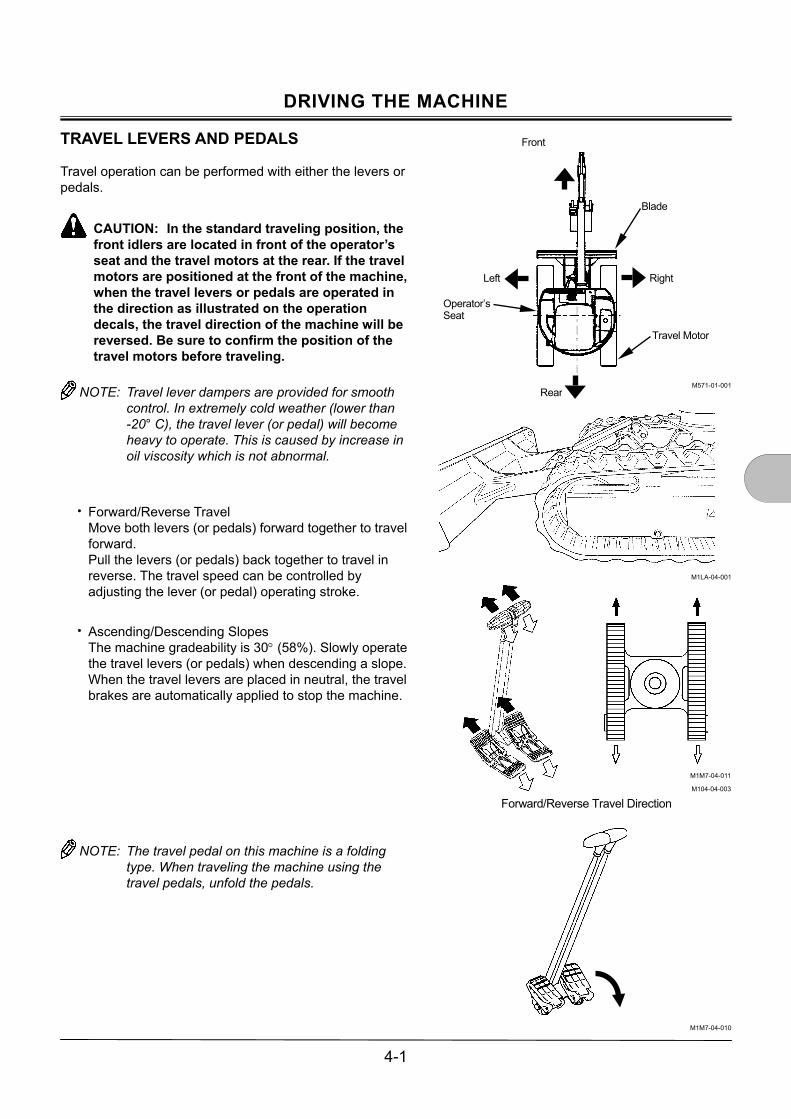
DRIVING THE MACHINE
4-1
TRAVEL LEVERS AND PEDALS
Travel operation can be performed with either the levers or pedals.
CAUTION: In the standard traveling position, the front idlers are located in front of the operator�s seat and the travel motors at the rear. If the travel motors are positioned at the front of the machine, when the travel levers or pedals are operated in the direction as illustrated on the operation decals, the travel direction of the machine will be reversed. Be sure to confirm the position of the travel motors before traveling.
NOTE: Travel lever dampers are provided for smooth
control. In extremely cold weather (lower than -20° C), the travel lever (or pedal) will become heavy to operate. This is caused by increase in oil viscosity which is not abnormal.
� Forward/Reverse Travel Move both levers (or pedals) forward together to travel forward. Pull the levers (or pedals) back together to travel in reverse. The travel speed can be controlled by adjusting the lever (or pedal) operating stroke.
� Ascending/Descending Slopes
The machine gradeability is 30° (58%). Slowly operate the travel levers (or pedals) when descending a slope. When the travel levers are placed in neutral, the travel brakes are automatically applied to stop the machine.
NOTE: The travel pedal on this machine is a folding type. When traveling the machine using the travel pedals, unfold the pedals.
M571-01-001
M1LA-04-001
M1M7-04-010
Front
Left
Operator�s Seat
Rear
Travel Motor
Right
Blade
M1M7-04-011
M104-04-003
Forward/Reverse Travel Direction

DRIVING THE MACHINE
4-2
� Pivot Turn Steer the machine by driving only one side crawler. Operate either of the travel levers (or pedals).
� Spin Turn Steer the machine in a position by driving both side crawlers in opposite directions each other. Move one lever (or pedal) forward and pull the other back at the same time.
CAUTION: During pivot or spin turn machine operations, the base machine may shake. When turning the machine in a tight area, slowly operate the machine while taking care not to allow the machine to come in contact with the surrounding objects.
M1M7-04-012
M104-04-005
M1M7-04-013
M104-04-007
Pivot Turn
Spin Turn

DRIVING THE MACHINE
4-3
TRAVEL MODE SWITCH
CAUTION: Never attempt to shift the travel mode from the slow to fast while descending a slope. Return the travel levers (pedals) to neutral once before shifting the travel mode.
Press the RABBIT mark side on travel mode switch (1) to select the fast travel mode. (The slow travel mode will automatically be selected if the traveling loads increase.) Press the TURTLE mark side on travel mode switch (1) to select the slow travel mode.
CAUTION: In cold weather season, when the machine is traveling with the travel mode switch in the fast travel mode position, the slow travel mode may not automatically be selected even if the traveling loads increase. This symptom is not abnormal. Drive the machine after conducting sufficient warm-up operation.
M1M7-01-033
M1M7-01-032
M1M7-01-036
M1M7-01-024
1
1
ZX30U-2, ZX35U-2, ZX40U-2, ZX50U-2 (Canopy)
ZX30U-2, ZX35U-2, ZX40U-2, ZX50U-2(Cab)
1
ZX27U-2 (Canopy)
1
ZX27U-2 (Cab)

DRIVING THE MACHINE
4-4
PRECAUTIONS FOR TRAVELING
CAUTION: Use a signal person when traveling the machine along road shoulders or in congested areas.
� Determine which way to move travel levers for the
direction you want to go before moving machine.
� Select a travel route that is as flat as possible. Steer the machine as straight as possible, making small gradual changes repeatedly in direction.
� Check the strengths of bridges and road shoulders before traveling on them, and reinforce if necessary.
� When the machine is equipped with steel shoes, cover the road surface with wood plates in order not to damage the road surface. Be careful of steering when operating on asphalt roads in summer.
� When crossing train tracks, lay wood plates over the tracks not to allow the machine to ride on only the rails.
� Check that the machine can pass under a bridge and electric lines before driving the machine.
� When crossing a river, drive the machine slowly while measuring the depth of the river using the bucket. Do not cross the river when the depth of the river is deeper than the upper track shoe surface.
� Reduce the engine speed when traveling on rough terrains. Select slow a travel speed. Slower speed will reduce possible damage to the machine.
� Drive the machine so that the travel motors do not come in contact with loose rocks. If the machine crosses over an obstruction, abnormally large loads may be loaded on the machine. Avoid contact with an obstruction while traveling the machine.
� During freezing weather, always clean snow and ice from track shoes before driving the machine on snowy and/or frozen roads, or loading and unloading the machine for transportation, to prevent the machine from slipping.
SA-673
SA-1305
M586-05-002

DRIVING THE MACHINE
4-5
TRAVELING ON SOFT GROUND
Avoid traveling on soft ground as much as possible. If traveling on a soft ground is unavoidable, carefully operate the machine while observing the following points.
� Drive the machine as far as the machine can move by own propelling power. Towing machine may become necessary. Don�t drive the machine to a deeper location than towing machine is possible.
� In case it becomes impossible for the machine to travel by own propelling power, lower the bucket to the ground. While supporting the machine weight with the boom and the arm, slowly pull the arm to evacuate the machine. Operate the boom, arm, and travel levers simultaneously at this time to prevent the machine from being loaded abnormally.
� If the track frame bottom come in contact with the ground, or if mud and/or grabbles are tightly packed into the undercarriage, the machine may become impossible to travel. Raise one side track above the ground with the boom and arm extended, remove mud and/or grabbles from the track. Then, evacuate the machine. Rotate the raised track in forward or reverse directions alternately to remove the packed rocks and/or mud from the track.
� Tow the machine with other machine if the machine becomes stuck in soft ground and impossible to evacuate by own propelling power. Refer to the descriptions for TOWING MACHINE on the next page for the correct rope attaching method.
RAISE ONE TRACK USING BOOM AND ARM
CAUTION: Operate the machine carefully. The machine may slide. Keep the angle between boom and arm 90° to 110° and position the bucket�s round side on the ground.
1. Swing the upperstructure 90°
2. Position the boom and the arm so that the angle between them becomes to 90° to 110°. Push the ground with the round bucket bottom to raise track off ground.
3. Do not raise the track with the boom and the arm when the boom is swung.
M1M7-04-005
M1M7-04-006
90 to 110°
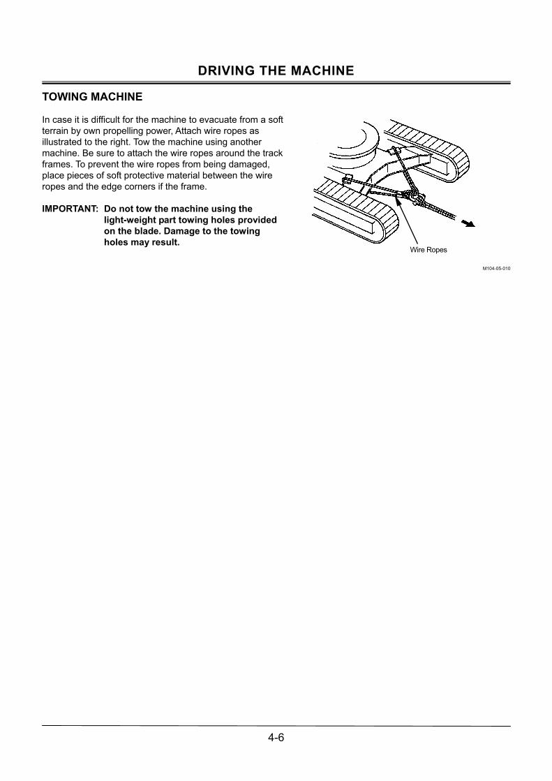
DRIVING THE MACHINE
4-6
TOWING MACHINE
In case it is difficult for the machine to evacuate from a soft terrain by own propelling power, Attach wire ropes as illustrated to the right. Tow the machine using another machine. Be sure to attach the wire ropes around the track frames. To prevent the wire ropes from being damaged, place pieces of soft protective material between the wire ropes and the edge corners if the frame. IMPORTANT: Do not tow the machine using the
light-weight part towing holes provided on the blade. Damage to the towing holes may result.
M104-05-010
Wire Ropes

DRIVING THE MACHINE
4-7
DRIVING IN WATER OR ON SOFT GROUND
1. If the footing is even and the water slow running, the machine can drive in water up to the upper track shoe surface (A) at the top of the front idler. In case the footing is uneven and the water is flowing fast, be careful not to submerge the swing bearing, swing pinion gears, and/or center joint in water or mud.
2. The machine may enter deeper areas gradually. Check the machine�s position often. Reposition the machine if necessary.
IMPORTANT: If the swing bearing, swing gears and
center joint are submerged in water or mud by mistake, premature wearing on parts such as the swing bearing may result. Grease must be changed or overhauling will be required immediately. Stop operating the machine as soon as possible, and contact your nearest Hitachi dealer.
M1M7-04-004
Machine Model Operable Water Depth (A)ZX27U-2 480 mm ZX30U-2, ZX35U-2 485 mm ZX40U-2, ZX50U-2 545 mm
A

DRIVING THE MACHINE
4-8
PRECAUTIONS FOR TRAVELING ON SLOPES
CAUTION: Avoid possible injury from traveling on slopes. Tipping over or skidding down of the machine may result. Be sure to travel at slow speed on slopes. Never attempt to travel on slopes with the bucket loaded or any load suspended by the bucket.
� Never attempt to ascend or descend 30 degrees or
steeper slopes.
� Be sure to fasten the seat belt. (Cab equipped machine)
� Keep the bucket pointed in the direction of travel, approximately 200 to 300 mm (8 to 12 in) (A) above the ground. If the machine skids or becomes unstable, immediately lower the bucket to the ground to stop traveling.
� Traveling across the face of slope or steering on a slope may cause the machine to skid or turnover. If the direction must be changed, move the machine to level ground, then, change the direction to ensure safe operation.
� Avoid swinging the upperstructure downhill. The machine may tip over. If swinging uphill is unavoidable, carefully operate the upperstructure and boom at slow speed.
� If the engine stalls on a slope, immediately lower the blade to the ground. Return the control levers to neutral. Then, restart the engine.
� Be sure to thoroughly warm up the machine before ascending steep slopes. If hydraulic oil has not warmed up sufficiently, sufficient driving power to ascend may not be obtained.
IMPORTANT: Traveling down a slope in the fast mode requires a longer time to stop the machine. When traveling down a slope, placing travel mode switch (1) in the TURTLE position is recommended.
M1M7-04-007
M1M7-04-008
M1M7-01-023
A
A1

DRIVING THE MACHINE
4-9
PARKING AND STOPPING ON SLOPES
CAUTION: Parking and/or stopping on slopes is extremely dangerous. Avoid parking and/or stopping the machine on slopes.
If parking and/or stopping on slopes is unavoidable, lower both the bucket and the blade to the ground, and place all levers in the neutral position. Also, put blocks at the downhill end of the tracks. PARKING ON SLOPES
1. Park the machine on a level, solid surface. Position the arm vertically and lower the bucket and blade to the ground.
2. Turn the engine control dial or the engine control lever to the slow idle position. Run the engine at the slow idle speed for approx. 5 minutes to cool the engine.
3. Turn the key switch to OFF to stop the engine. Remove the key from the switch.
4. Pull pilot control shut-off lever (1) into the fully LOCK position.
5. Close the window and cab door, if a cab is provided. Be sure to lock all the cab doors and windows.
M1M7-04-009
M1M7-03-001
1

DRIVING THE MACHINE
4-10
MEMO
.....................................................................................................................................................................................
.....................................................................................................................................................................................
.....................................................................................................................................................................................
.....................................................................................................................................................................................
.....................................................................................................................................................................................
.....................................................................................................................................................................................
.....................................................................................................................................................................................
.....................................................................................................................................................................................
.....................................................................................................................................................................................
.....................................................................................................................................................................................
.....................................................................................................................................................................................
.....................................................................................................................................................................................
.....................................................................................................................................................................................
.....................................................................................................................................................................................
.....................................................................................................................................................................................
.....................................................................................................................................................................................
.....................................................................................................................................................................................
.....................................................................................................................................................................................
.....................................................................................................................................................................................
.....................................................................................................................................................................................
.....................................................................................................................................................................................
.....................................................................................................................................................................................
.....................................................................................................................................................................................
.....................................................................................................................................................................................
.....................................................................................................................................................................................
.....................................................................................................................................................................................
.....................................................................................................................................................................................
.....................................................................................................................................................................................
.....................................................................................................................................................................................

OPERATION
5-1
CONTROL LEVER (ISO EXCAVATOR PATTERN)
CAUTION: Be sure to check the location and function of each control lever before operating. The upperstructure and/or front attachment may unexpectedly move when attempting to turn and look behind the machine as a part of operator�s body may come into contact with the control lever(s). Take care not to come into contact with the control levers when turning and looking behind the machine.
Labels showing the lever control pattern are provided on the operator�s right. As illustrated below, the labels indicate the ISO Excavator Pattern.
M588-05-050
When a control lever is released, it automatically returns to neutral, stopping the function in that position.
1- Arm Roll-Out
2- Arm Roll-In
3- Swing Left
4- Swing Right
5- Boom Lower
6- Boom Raise
7- Bucket Roll-In
8- Bucket Roll-Out
M1M7-01-002
M1M7-05-001
M1M7-05-002
4
3
1
2
8
75
6
43
2
1
6
5
7 8
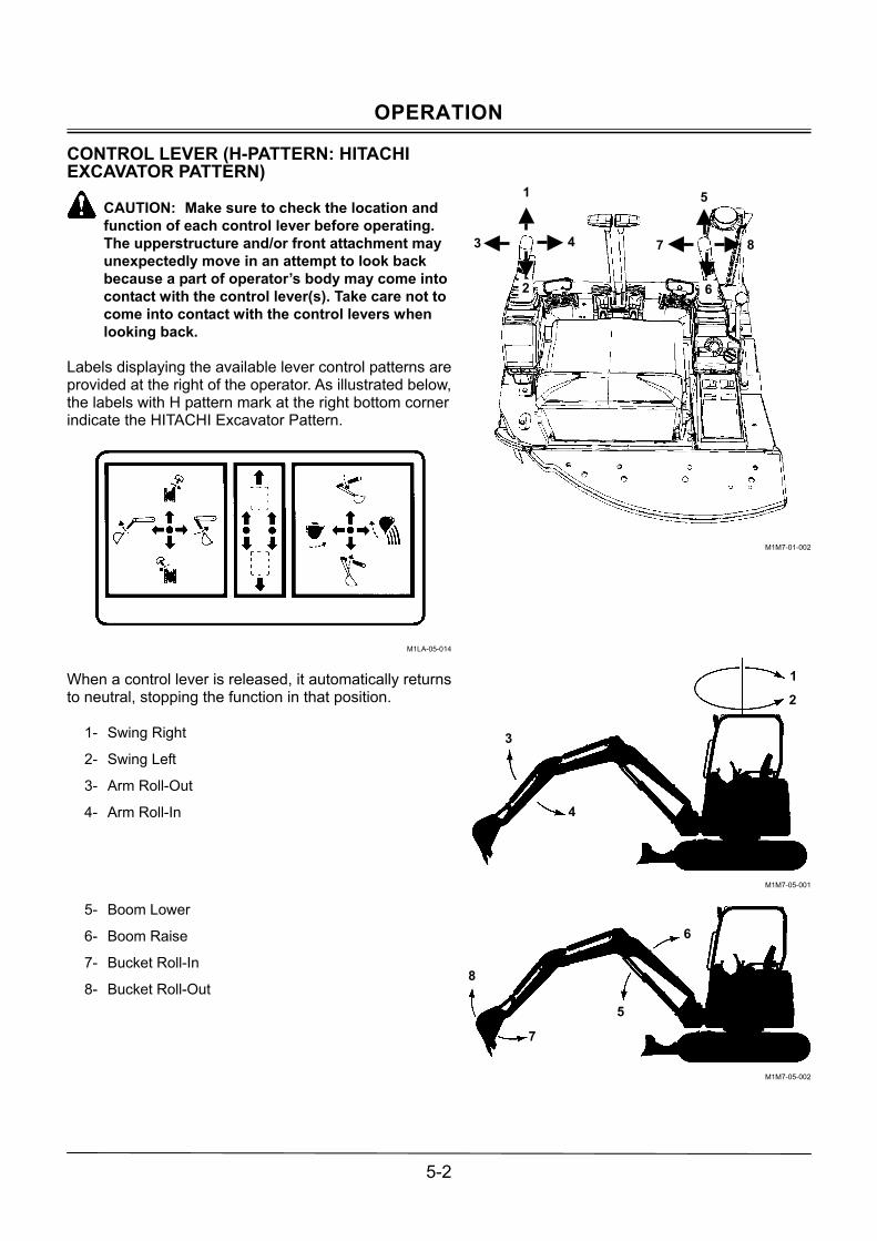
OPERATION
5-2
CONTROL LEVER (H-PATTERN: HITACHI EXCAVATOR PATTERN)
CAUTION: Make sure to check the location and function of each control lever before operating. The upperstructure and/or front attachment may unexpectedly move in an attempt to look back because a part of operator�s body may come into contact with the control lever(s). Take care not to come into contact with the control levers when looking back.
Labels displaying the available lever control patterns are provided at the right of the operator. As illustrated below, the labels with H pattern mark at the right bottom corner indicate the HITACHI Excavator Pattern.
M1LA-05-014
When a control lever is released, it automatically returns to neutral, stopping the function in that position.
1- Swing Right
2- Swing Left
3- Arm Roll-Out
4- Arm Roll-In
5- Boom Lower
6- Boom Raise
7- Bucket Roll-In
8- Bucket Roll-Out
M1M7-01-002
M1M7-05-001
M1M7-05-002
43
2
1
6
5
7 8
1
2
3
4
8
7
5
6
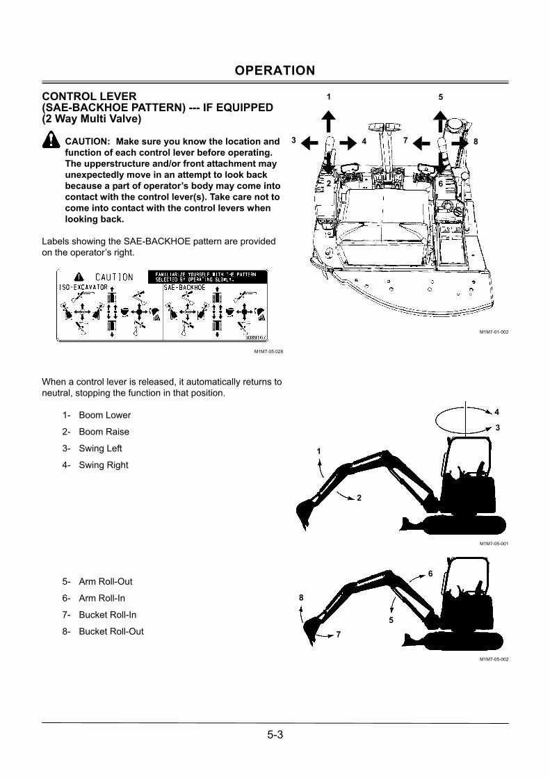
OPERATION
5-3
CONTROL LEVER (SAE-BACKHOE PATTERN) --- IF EQUIPPED (2 Way Multi Valve)
CAUTION: Make sure you know the location and function of each control lever before operating. The upperstructure and/or front attachment may unexpectedly move in an attempt to look back because a part of operator�s body may come into contact with the control lever(s). Take care not to come into contact with the control levers when looking back.
Labels showing the SAE-BACKHOE pattern are provided on the operator�s right.
M1M7-05-028
When a control lever is released, it automatically returns to neutral, stopping the function in that position.
1- Boom Lower
2- Boom Raise
3- Swing Left
4- Swing Right
5- Arm Roll-Out
6- Arm Roll-In
7- Bucket Roll-In
8- Bucket Roll-Out
M1M7-01-002
M1M7-05-001
M1M7-05-002
4
2
3
1
8
6
7
5
4
3
1
2
8
75
6

OPERATION
5-4
BOOM-SWING PEDAL
Use the boom swing function to efficiently operate the machine when excavating grooves along roadsides or near walls. The boom swing operation is performed using boom-swing pedal (1) located at the operator�s right foot as illustrated to the right
Boom-Swing Operation
1. Turn cover (2) for boom-swing pedal (1) forward.
2. Step on the left side of boom-swing pedal (1) to swing left. Step on the right side of the pedal to swing right.
3. Turn cover (2) backward over boom-swing pedal (1) when boom-swing operation is no longer required.
3- Swing Left
4- Swing Right
M1M7-05-005
M1M7-05-006
M571-01-001
2
3 4
Unlock Position
1
2
Lock Position

OPERATION
5-5
AUXILIARY PEDAL (OPTIONAL)
Use the auxiliary pedal (2) located at the operator�s left front, as illustrated to the right, to operate hydraulic breaker, crusher, etc.
Operation
1. Turn auxiliary pedal cover (1) forward.
2. Step on the right or the left side of the auxiliary pedal (2) to operate the front-end attachment such as a hydraulic breaker
3. When the auxiliary pedal (2) is not used, turn cover (1) backward on the pedal.
M1M7-05-0079
M1M7-05-008
2
1
1

OPERATION
5-6
BLADE LEVER
Use blade lever (1) on the operator�s right to raise and lower the blade. When the lever is released, it automatically returns to neutral, holding the blade in the present position until the lever is operated again.
2- Blade Raise
3- Blade Lower
M1M7-05-009
M1M7-04-004
2
3
3 2
1

OPERATION
5-7
PRECAUTIONS FOR BLADE OPERATION
This blade is designed as a light service attachment of the hydraulic excavator. Please keep the following points in mind:
� This blade is designed for bull dozing work only. Do not attempt to dig deeply with the blade. Doing so may damage not only the blade but the undercarriage as well.
� Do not apply concentrated or uneven loads to the blade. Never allow the blade to forcefully collide with a load by running the machine into the load. Failure to do so may result in damage to the blade and the undercarriage.
� When jacking up the machine with this blade, the surface beneath the blade comes under high pressure, increasing the risk of surface collapse. Always be sure that the surface is strong enough to support the weight of the machine before jacking up the machine. Avoid dangerous uneven distribution of weight to the blade by maintaining even contact between the blade and the ground.
� While digging with the blade positioned in the front of the machine, take care not to allow the bucket to come into contact with the blade.
� When digging, take care not to allow the boom cylinder to come in contact with the blade.
M586-05-016
M586-05-017
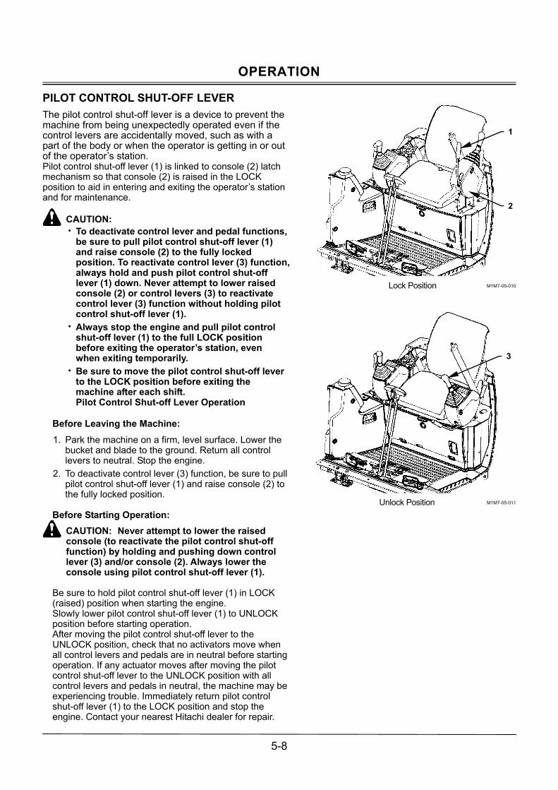
OPERATION
5-8
PILOT CONTROL SHUT-OFF LEVER The pilot control shut-off lever is a device to prevent the machine from being unexpectedly operated even if the control levers are accidentally moved, such as with a part of the body or when the operator is getting in or out of the operator�s station. Pilot control shut-off lever (1) is linked to console (2) latch mechanism so that console (2) is raised in the LOCK position to aid in entering and exiting the operator�s station and for maintenance.
CAUTION: � To deactivate control lever and pedal functions,
be sure to pull pilot control shut-off lever (1) and raise console (2) to the fully locked position. To reactivate control lever (3) function, always hold and push pilot control shut-off lever (1) down. Never attempt to lower raised console (2) or control levers (3) to reactivate control lever (3) function without holding pilot control shut-off lever (1).
� Always stop the engine and pull pilot control shut-off lever (1) to the full LOCK position before exiting the operator�s station, even when exiting temporarily.
� Be sure to move the pilot control shut-off lever to the LOCK position before exiting the machine after each shift. Pilot Control Shut-off Lever Operation
Before Leaving the Machine: 1. Park the machine on a firm, level surface. Lower the
bucket and blade to the ground. Return all control levers to neutral. Stop the engine.
2. To deactivate control lever (3) function, be sure to pull pilot control shut-off lever (1) and raise console (2) to the fully locked position.
Before Starting Operation:
CAUTION: Never attempt to lower the raised console (to reactivate the pilot control shut-off function) by holding and pushing down control lever (3) and/or console (2). Always lower the console using pilot control shut-off lever (1).
Be sure to hold pilot control shut-off lever (1) in LOCK (raised) position when starting the engine. Slowly lower pilot control shut-off lever (1) to UNLOCK position before starting operation. After moving the pilot control shut-off lever to the UNLOCK position, check that no activators move when all control levers and pedals are in neutral before starting operation. If any actuator moves after moving the pilot control shut-off lever to the UNLOCK position with all control levers and pedals in neutral, the machine may be experiencing trouble. Immediately return pilot control shut-off lever (1) to the LOCK position and stop the engine. Contact your nearest Hitachi dealer for repair.
M1M7-05-010
M1M7-05-011
2
3
Lock Position
Unlock Position
1

OPERATION
5-9
WARMING UP OPERATION
The normal operating temperature of hydraulic oil is between 50 and 80°C (122 and 176°F). Hydraulic components may be seriously damaged if the machine is operated when the hydraulic oil temperature is below 20°C (68°F). Before starting work, be sure to follow these warm-up procedures until the temperature of the hydraulic oil reaches above 20°C (68°F).
Warm-Up Procedures:
1. Run the engine at 100 to 200 min-1 (rpm) above slow idle speed for 5 minutes.
2. With the engine speed control lever or the engine speed control dial at the medium position, run the engine for 5 to 10 minutes.
3. Extend and retract each cylinder several times and lightly operate the swing and travel motors to warm up them.
WARMING UP IN COLD WEATHER
IMPORTANT: In case the hydraulic oil temperature is low, never operate the machine until all actuator speeds become normal after warming up operation.
1. Run the engine at intermediate speed for 5 minutes
(longer if the air temperature is extremely low).
2. Do not run the engine at either slow or fast speed during this time.
3. Extend and retract each cylinder several times and lightly operate the swing and travel motors to warm up them.
4. Extend the bucket cylinder to the stroke end. Be sure not to hold the bucket lever in this position for more than 30 seconds.
5. Retract the bucket cylinder to the other stroke end. Be sure not to hold the bucket lever in this position for more than 30 seconds.
6. Repeat steps 4 to 5 until the bucket cylinder cycle time becomes normal.

OPERATION
5-10
AUTO-IDLE CONTROL (Except ZX27U-2)
Auto-Idle Function
During operation, approximately 4 seconds after all control levers have been returned to neutral, this system reduces the engine speed to the auto-idle setting until any control lever is operated again to improve fuel consumption. The engine speed immediately increases to the speed set by the engine control dial when any control lever is operated.
CAUTION: � Always check if auto-idle indicator (2) is turned
ON or OFF before starting operation. When the indicator is ON, the auto-idle function will operate.
� When any control lever is operated from the neutral position with auto-idle switch (1) turned ON, the engine speed will increase to the speed set by the engine control dial. Therefore, always be aware of engine control dial setting before starting operation to prevent the engine speed from increasing unexpectedly.
� When unexpected machine movement could be dangerous, such as when loading/unloading the machine for transportation, or when the machine is engaging in lifting work, turn auto-idle switch (1) OFF to ensure safe operation.
� Use the auto-idle function only after warm-up operation is complete. Failure to do so may not reduce the engine speed.
Note that the auto-idle function can be turned ON or OFF only when the key switch is in the ON position. Check if the auto-idle function is turned ON or OFF with auto-idle indicator (2).
Auto-Idle Switch
ON: Auto-idle indicator (2) ON. OFF: Auto-idle indicator (2) OFF. After the key switch is turned OFF when the auto-idle function is activated [with auto-idle indicator (2) ON], when the engine is restarted, the auto-idle indicator flashes for 10 seconds and the auto-idle function becomes activated later.
M1M7-01-028
2
1

OPERATION
5-11
PRECAUTIONS FOR OPERATIONS
CAUTION: Thoroughly make certain safety at the work site before starting operations. Especially always observe the following points. � Be sure to install the overhead cab guard
before operating the machine in areas where the possibility of falling stones or debris exists.
� If operation on soft ground is required, sufficiently reinforce the ground beforehand.
� Be sure to wear close fitting clothing and required
safety items, such as a hard hat, when operating the machine.
� Keep all bystanders and unnecessary objects out of and away from the machine working areas. Always beware of the surroundings while operating the machine. Take care not to allow the rear part of the upperstructure to come in contact with objects when swinging the machine in a small area.
� When loading a dump truck, bring the bucket from the rear side of the dump truck to avoid moving the bucket over the dump truck cab or over any co-workers.
OPERATE MACHINE SAFELY
CAUTION: Prevent the machine from tipping over and from being involved in a ground collapse. Take the following necessary precautions: � Make sure the work site ground has sufficient
strength to firmly support the machine. When working close to an excavation or on road shoulders, operate the machine with the tracks positioned perpendicular to the cliff face with travel motors at the rear and with the blade at the front, so that the machine can more easily evacuate if the cliff face collapses.
� If working at the bottom of a cliff or on a high bank is required, be sure to investigate the area first and confirm that no danger of the cliff or bank collapsing exists. If any possibility of cliff or bank collapsing exists, do not work in that area.
� Soft ground may collapse when operating the machine on it, possibly causing the machine to tip over. When working on a soft ground is required, be sure to reinforce the ground first using large pieces of steel plates strong enough and firm to easily support the machine.
� Note that there is always a possibility of machine tipping over when working on rough terrain or on slopes. Prevent machine tipping over from occurring. Operate the machine slowly to ensure safe operation.
M586-12-012
M586-05-021

OPERATION
5-12
OPERATING BACKHOE
� Select an arm and bucket whose specifications match the working conditions. (Refer to �Kinds and Applications of Buckets� in the specification section.)
� Pull the bucket toward the machine using the arm as the main digging force.
� When soil sticks to the bucket, remove it by moving the arm and/or bucket rapidly back and forth a few times.
� While facing the bucket tooth tip toward the direction of excavation as straight as possible, excavate the ground with the teeth penetrating shallowly using the arm and bucket cylinder full strokes.
� Position the tracks parallel to the trench. After digging to the desired depth, move the machine backward to continue the trench.
� Operate each cylinder with a slight allowance left at both stroke ends.
IMPORTANT:
� Do not dig the ground in the diagonal direction toward the track frame. Failure to do so may cause the bucket teeth to come in contact with the crawler.
� When lowering the boom, avoid sudden stops that may create shock load damage to the machine. Always smoothly lower the boom so that shock loads may not be created.
� When digging deep below the ground level, be careful not to allow boom cylinder, boom bottom, and/or bucket cylinder hoses to come in contact with the ground.
� When digging with the blade positioned towards the front or when digging at an angle, avoid hitting the blade.
� When the bucket load is dumped with the boom raised, falling material may hit the base machine and/or the canopy. Always be aware of loads in the bucket during operation.

OPERATION
5-13
GRADING OPERATION
Use the blade for soil refilling and general grading operations after excavation. Grading operation can be also performed by operating the boom, arm, and bucket simultaneously. IMPORTANT: When grading the ground with the
bucket, do not pull or push dirt with the bucket while traveling the machine like a bulldozer. Every part of machine may receive excessively large loads, possibly resulting in damage to the machine.
When grading by operating the boom, arm, and bucket simultaneously:
1. When grading from the forward to the backward, slowly roll in the arm while slightly raising the boom. As soon as the arm passes the vertical position, slowly lower the boom so that the bucket can be horizontally moved.
2. When grading from the backward to the forward, operated the arm and bucket rolled back, as shown.
Grading a slope surface can be performed by operating the machine in the same method as mentioned above.
AVOID DRIVING BUCKET TEETH INTO GROUND
CAUTION: If the bucket teeth are forcedly driven into the ground, crushed material may spatter, possibly resulting in injury of the operator and/or co-workers around the machine. Furthermore, the service lifetimes of all front attachment parts may be shortened.
If the bucket teeth are forcedly driven into the ground, the service lifetime of all front attachment parts (especially the bucket) may be severely shortened. When excavating tightly fastened gravelly soil, use the bucket digging out force. Operate the boom, arm, and bucket simultaneously so that the bucket teeth can be effectively penetrated into the excavation surface. Carefully operate the machine to prevent crushed material from spattering, possibly resulting in injury to the operator and/or co-workers around the machine.
AVOID ABUSIVE OPERATION If digging force is increased by driving the machine while pushing the bucket into the ground, or by raising the rear of the machine to apply the machine weight to the bucket teeth, severe machine damage may result due to excessive overloading.
M1M7-05-012
M1M7-05-013
WRONG
WRONG

OPERATION
5-14
AVOID STRIKING WITH BUCKET
CAUTION: The bucket bottom is curved. Therefore, hammering or piling work with the bucket is very hazardous. In addition, damage to the bucket and the front attachment parts may result.
Hammering or piling work with the bucket may create hazardous situations. Never attempt to perform hammering or piling work with the bucket. Damage to the bucket and the front attachment parts may also result. AVOID EXCAVATION USING UPPERSTRUCTURE AND/OR BOOM SWING POWER
Never attempt to move rocks or excavate a cliff face by hitting the bucket using upperstructure and/or boom swing power. Damage to the front attachment, or shortening of the service life of the swing systems may result. USE CORRECT TRACK SHOE
Never use rubber crawlers or wide track shoes on rough terrain with scattered rocks, gravel or boulders. Failure to do so may cause breakages of rubber crawlers, shoe bending, looseness of shoe bolts, or damage to track parts such as track links, or rollers. (Refer to the table for Types and Applications of Track Shoes in the specification section. Soil may easily become packed into the crawler during travel operation on sandy ground. If the machine is driven without removing the packed soil from the crawlers, the rubber crawlers will be overloaded, possibly resulting in breakage of the crawlers. Avoid causing the crawlers to become packed with soil by removing soil as often as possible.
M1M7-05-014
M1M7-05-015
WRONG

OPERATION
5-15
AVOID OTHER THAN SPECIFIED MACHINE OPERATIONS
This machine has been exclusively designed for excavation and loading works.
Do not apply this machine to works other than excavation and loading. Do not operate the machine under any conditions beyond the these specifications.
Precautions for Lifting Work
� Operate the machine on level ground. Operating the machine on a slope may cause the machine to become unstable, possibly resulting in tipping accident.
� When lifting a load, carefully swing the machine not to cause the lifting load to come in contact with personnel working near the machine. Reduce the engine speed to slowly swing the machine. Failure to do so may cause the machine to tip over by swing centrifugal force.
� If traveling the machine with a load lifting is unavoidable, reduce the engine speed to slowly travel the machine.
� Never move the front attachment and/or swing the machine while traveling the machine with a load lifting. The lifted load may sway, possibly creating a hazardous situation.

OPERATION
5-16
PRECAUTIONS FOR USING BUCKET HOOK
CAUTION: Even though a hook equipped with a wire rope guide is used, wire rope may come off the bucket hook if the machine is improperly operated.
During lifting work of objects such as steel planks, steel building materials, or electric concrete masts, when the lifted object is lowered to the ground, the wire rope may come off the bucket hook. To prevent wire rope from coming off the hook, never allow the wire rope to slacken by operating the front attachment as slowly as possible. Do not allow anyone to enter below the lifted load or in the vicinity of the lifted load. Control the bucket angle so that the bucket hook mounting face remains vertical as illustrated to the right. BOOM CYLINDER MAY HIT BLADE
When digging deeply with the blade positioned at the front, the boom cylinder or bucket may accidentally hit the blade, causing damage. Take care to prevent this from happening.
SA-525
M586-05-016
M586-05-017

OPERATION
5-17
AVOID HITTING BLADE WITH BUCKET
When rolling in the arm in a travel or transportation position, be careful not to hit the blade with the bucket. AVOID COLLIDING BLADE AGAINST ROCKS
Do not attempt to allow the blade to collide with rocks. Premature damage to the blade and the blade cylinders may result. AVOID COLLIDING BOOM CYLI NDER WITH TRACK
When digging deeply with the front attachment positioned at an angle, as illustrated, the boom cylinder may accidentally collide with the track, causing damage. Take extra care to prevent this from happening. PRECAUTIONS FOR INSTALLING WIDE BUCKET OR SPECIAL TYPE BUCKET
If the boom is fully offset to the left and raised on the cab-equipped machine with a bucket wider than shown below installed, the bucket will come in contact with the cab. Be sure to install a specially arranged bucket only after consulting your nearest Hitachi dealer to prevent the cab collision with the bucket.
M586-05-017
M586-05-035
M586-05-018
ZX27U-2 : 600 mm (24 in) ZX30U-2 : 600 mm (24 in) ZX35U-2 : 600 mm (24 in) ZX40U-2 : 600 mm (24 in) ZX50U-2 : 650 mm (26 in)

OPERATION
5-18
USING RUBBER CRAWLER
Rubber crawlers are designed to allow the machine to travel without damaging road surfaces such as paved road surfaces. Avoid damage to the rubber crawlers by following the precautions below:
Forbidden Operations
1. Do not operate or steer the machine on or near river-terrace, boulder and boulder mixed ground, crushed-stone ground, uneven hardpan surfaces, stumps, reinforcing bars, scraps, and steel plate edges. Failure to do so may shorten the service life of the rubber crawlers to a great extent.
2. Do not leave engine oil, fuel, and other kinds of lubricants remaining on the rubber crawlers, and avoid traveling on road surface covered with oil to reduce the danger of sliding.
3. Do not travel the machine while raising one side crawler off the ground with the front attachment. Shear or damage to the rubber crawler may result.
Precautions for Using Rubber Crawlers
CAUTION: The rubber crawler machine is less stable than the steel crawler machine, as the edge of the rubber crawler is easier to deform more than steel crawler. Pay attention when operating the machine at an angle to the tracks.
1. Do not store the rubber crawlers in a place where
they will be exposed to direct sunlight for a period of more than three months.
2. Avoid unnecessary steering operations on concrete roads, possibly resulting in premature wear of shoe lugs and core metals. Also, avoid operating the machine on high temperature [over 60°C (140°F)] road surfaces during asphalt pavement work, possibly causing premature wear of the rubber crawlers as well as damage to the road surface.
M1M7-05-015
M1M7-05-016

OPERATION
5-19
3. Operating the machine with rubber crawlers sagging on uneven surfaces can result in derailment of rubber crawler, possibly causing the rubber crawlers to be damaged.
4. When lowering the machine raised above the ground using the front attachment, slowly lower the machine to the ground.
5. The new rubber crawler has a thin rubber film (shown in doted line) on its roller tread. During operation of a new machine, or immediately after the rubber crawlers are replaced, the rubber film may come off due to contact with the rollers. This is not abnormal. (See the right illustration.)
6. If the rubber crawler is damaged and the rubber crawler core wire rusts, the service lifetime of the rubber crawler will become short. If damaged, the rubber crawler must be repaired. Contact your nearest Hitachi dealer.
M586-05-024
M503-05-040
Roller
Film
Rubber Crawler

OPERATION
5-20
HYDRAULIC BREAKER (OPTIONAL)
Before installing a hydraulic breaker to the machine, change in machine stability, and the hydraulic pressure and flow rate to operate the hydraulic breaker must be checked. Consult your nearest Hitachi dealer for selection of the hydraulic breaker model to be installed. Refer to the Breaker Operation Manual for operation of the hydraulic breaker. Observe the following instructions to prevent the base machine and the hydraulic breaker from being damaged.
Precautions for Installing Hydraulic Breaker Pipe Lines
� When disconnecting or reconnecting the hydraulic breaker hoses from or to the hydraulic pipe lines at the arm tip, take care not to allow dust to stain or enter the inside of pipes and hoses.
� When the hydraulic breaker is not installed, be sure to put caps or plugs to the arm tip pipe open ends and the hydraulic breaker side hose ends to prevent the hydraulic system from being contaminated by dust. Be careful not to lose the caps and plugs. Always keep the auxiliary parts in the tool box.
� Check that the pipe clamp bolts are tight, and no oil is leaking from the pipe and hose joints before operating the hydraulic breaker.
Precautions for Hydraulic Breaker Operation
CAUTION: When the hydraulic breaker is installed, machine stability is reduced as the breaker is much heavier than the bucket. In addition, soil, broken pieces of rock or metals may be scattered during breaker operation, potentially creating hazardous situation. Take protective measures against danger of machine tipping over and/or scattering of hard materials and observe the precautions described below to ensure safe operation.
1. Avoid crashing the breaker onto hard materials.
The breaker is heavier than the bucket, causing the lowering speed of the breaker to become faster. If breaking hard materials by crashing the breaker onto hard materials is attempted, damage to the front attachment and/or the upperstructure may result due to accelerated crashing reaction force.
2. Do not move crushed materials using the breaker unit and/or the swing function. Damage to the boom, arm, and/or breaker may result.
M1M7-05-020
M585-05-020
WRONG
WRONG

OPERATION
5-21
3. Do not operate the breaker with the hydraulic cylinders fully extended or retracted. When operating the breaker, position each hydraulic cylinder so that the allowance more than 50 mm from the stroke end can be given before the cylinder piston comes in contact with the cylinder head or bottom. Failure to do so may result in damage to the hydraulic cylinders, arm and/or boom.
4. Do not operate the breaker in water. Seals may become broken due to rusting of the breaker, possibly allowing rust, dust, and/or water to enter the hydraulic circuit so that damage to the hydraulic components on the base machine may result.
5. Do not use the breaker to lift objects. Serious accidents may result due to tipping over of the machine and/or coming off of the lifted load.
6. Do not operate the breaker over the side of the machine. The machine stability is reduced, possibly resulting in tipping over of the machine. In addition, the service lifetime of the undercarriage may become shorter due to receiving more severe breaker operation reaction force.
M1M7-05-021
M104-05-059
M1M7-05-022
M1M7-05-017
WRONG
WRONG
WRONG
WRONG
WRONG
RIGHTRIGHT

OPERATION
5-22
7. Do not allow the breaker chisel to come in contact with the boom when rolling in the arm and the breaker.
8. Change hydraulic oil and replace the full flow filter element at the regular intervals. Hydraulic breaker operation subjects hydraulic oil to become contaminated and/or deteriorated more quickly than bucket operation. Failure to perform proper maintenance of hydraulic oil may cause the base machine and/or the breaker to malfunction. Be sure to change hydraulic oil and replace the full flow filter element at the intervals as shown in the table below to especially extend the service life of the hydraulic pump. (Refer to the Hydraulic System group in the Inspection and Maintenance Section.)
Hydraulic Oil change and Full Flow Filter Element
Replacement Intervals (Hours)
M1M7-05-027
9. Greasing Front Attachment
When using a hydraulic breaker, grease all lubrication points on the front attachment every 50 hours of operation.
M1M7-05-023
100%
Hours to Replace Element
Aver
age
Brea
ker O
pera
ting
Avai
labi
lity
Hours to Replace Hydraulic Oil
Excavator Operating Hours
80%
60%
40%
20%
0%0 1500 20001000 500
Watch Out! Take care not to hit the boom with the breaker

OPERATION
5-23
CRUSHER OPERATION (OPTIONAL)
Before installing a hydraulic crusher on the machine, machine stability, and the hydraulic pressure and flow rate to operate the hydraulic crusher must be checked. Consult your nearest Hitachi dealer for selection of the hydraulic crusher model to be installed. Refer to the Crusher Operation Manual for operation of the hydraulic crusher. Observe the following instructions to prevent the base machine and the hydraulic crusher from being damaged.
Precautions for Hydraulic Crusher Operation
CAUTION: When the hydraulic crusher is used in demolition work, machine stability is reduced as the crusher attachment is much heavier than the bucket. In addition, soil, broken pieces of rock or metals may be scattered during crusher operation, potentially creating hazardous situation. Take protective measures to prevent machine tipping over and/or scattering of hard materials and observe the precautions described below to ensure safe operation.
� Do not raise the base machine off the ground with the
bucket cylinder fully retracted or extended. Damage to the front attachment may result. In particular, avoid operating the machine with the bucket cylinder fully extended. The bucket cylinder may easily become damaged under this condition. Use extra care to prevent the bucket cylinder from being damaged during demolition work of structure foundations.
� Operate the crusher over the front or rear side of the machine. Operating the breaker over the side of the machine will reduce the machine stability, possibly resulting in tipping over of the machine.
M107-05-046
M107-05-047

OPERATION
5-24
� When crushing objects in high positions such as a ceiling, carefully operate the machine so that falling objects do not come in contact with the machine.
� Before operating the machine on a floor of structures, check that the strength of the floor is enough to support the machine weight. Depending on type of work the machine is engaged in, crushing reaction force may be added to the floor beside the machine weight.
� Start operation only after the machine is horizontally parked and the footing is stabilized. Never operated the machine positioned on stacks of rubble, or inclined grounds.
� Do not move or load crushed materials using the crusher.
� When replacing the crusher with other work tools such as a bucket or breaker, the hydraulic oil may easily become contaminated. Change the hydraulic oil and replace the full flow filter element at the same intervals as applied to the hydraulic breaker.
� Before transporting the machine on a trailer, remove the crusher from the front attachment. Position the bucket cylinder so that the cylinder is not fully extended during transportation. (During transportation, the machine may be raised off the trailer deck floor due to vibration as mentioned in Step 1, possibly resulting in damage to the front attachment.
PRECAUTIONS FOR AFTER OPERATING THE MACHINE
1. After operating the machine, move the machine to a level solid ground where no possibility of falling stones, landslide, or flooding is present. (Refer to the Parking group in the Driving Machine section.)
2. Fully refill the fuel.
3. Clean the machine.
4. During cold weather season, remove the coolant from the radiator and the water jacket. Attach �No Coolant � tag in an easy-to-see place.
M107-05-048
M107-05-049
M1M7-05-024
WRONG
WRONG

OPERATION
5-25
AUXILIARY FLOW RATE CONTROL (OPTIONAL) (Except ZX27U-2)
The maximum and minimum hydraulic flow rate in the auxiliary pipe line can be controlled as follows: ZX30U-2
ZX35U-2 ZX40U-2 ZX50U-2
ref. ZX27U-2
Minimum Flow Rate 40 L/min 45 L/min − Maximum Flow Rate 66 L/min 85 L/min 53 L/min
Flow Rate Control Selector
LOW: sets to the minimum flow rate. HIGH: sets to the maximum flow rate.
When shifting the flow rate from the LOW to HIGH, operate the switch while pulling the lock knob toward the arrow mark.
NOTE: When shifting the flow rate from the HIGH to
LOW, no lock knob operation is required.
M1M7-05-026
M1M7-01-024
M1M7-05-025
8
8 (Canopy)
(Cab)
Lock Knob

OPERATION
5-26
MEMO
.....................................................................................................................................................................................
.....................................................................................................................................................................................
.....................................................................................................................................................................................
.....................................................................................................................................................................................
.....................................................................................................................................................................................
.....................................................................................................................................................................................
.....................................................................................................................................................................................
.....................................................................................................................................................................................
.....................................................................................................................................................................................
.....................................................................................................................................................................................
.....................................................................................................................................................................................
.....................................................................................................................................................................................
.....................................................................................................................................................................................
.....................................................................................................................................................................................
.....................................................................................................................................................................................
.....................................................................................................................................................................................
.....................................................................................................................................................................................
.....................................................................................................................................................................................
.....................................................................................................................................................................................
.....................................................................................................................................................................................
.....................................................................................................................................................................................
.....................................................................................................................................................................................
.....................................................................................................................................................................................
.....................................................................................................................................................................................
.....................................................................................................................................................................................
.....................................................................................................................................................................................
.....................................................................................................................................................................................
.....................................................................................................................................................................................
.....................................................................................................................................................................................
TRANSPORTING
6-1
TRANSPORTING BY ROAD
When transporting the machine on public roads, be sure to first be aware of and then, follow all local regulations.
1. Before transporting the machine on a trailer, check the width, height, length, and weight of the trailer with the machine loaded.
2. Investigate the conditions of the route to be traveled, such as dimensional limits, weight limits, and traffic regulations, beforehand. In some cases, disassemble the machine to bring it within dimensional limits, or weight limits of local rules and regulations.
TRAILER LOADING/UNLOADING
Always load and unload the machine on a firm level surface.
CAUTION: Be sure to use a loading dock or a ramp when loading/unloading the machine.
Ramp/ Loading Dock
1. Thoroughly clean the ramp and flatbed. Dirty flatbed ramps contaminated with oil, mud, or ice can be slippery and dangerous.
2. Wedge the trailer wheels with blocks so that the trailer doesn�t move.
3. Ramps must be sufficient in length, width, and strength. Secure the ramp with an inclination of less than 15 degrees.
4. Loading docks must be sufficient in length, width, and strength. Inclination of the loading docks must be less than 15 degrees.
5. When loading/unloading the machine on a trailer, be careful not to allow the blade to come in contact with the ramps or loading docks.

TRANSPORTING
6-2
LOADING
CAUTION: � Always turn the auto-idle switch OFF. (Except
ZX27u-2) Failure to do so may cause the engine speed to suddenly change.
� Always travel the machine slowly. Press the travel mode switch (1) toward the TURTLE
side.
� Steering on a ramp may create a danger of tipping over. Never attempt to change travel direction on a ramp, possibly causing the machine to become unstable. If steering is unavoidable, first move back to the ground, modify traveling direction, and begin to drive again.
� The top end of the ramp where it meets the flatbed, there is a sudden bump. Slowly drive over it.
� Use extra care when rotating the upperstructure on the flatbed to prevent possible injury from machine tipping. Slowly rotate the upperstructure with the arm fully rolled in under the boom to maintain the good machine stability.
1. Load the machine on the trailer so that the centerline of the machine aligns with the centerline of the flatbed.
2. Drive the machine onto the ramp slowly.
3. Position the bucket above the flatbed. Operate the front attachment so that the angle between the boom and the arm is maintained at 90 to 110°.
4. The machine tips forward when the machine travels over the top end of the ramp. Lower the bucket onto the flatbed before the machine begins to tip forward.
5. After the machine reaches the specified position, slightly lift the bucket up off the flatbed. Slowly rotate the upperstructure 180° while keeping the arm fully rolled in.
6. Lower the bucket on wooden blocks seated on the flatbed.
7. Stop the engine. Remove the key from the switch.
8. Move the pilot control shut-off lever to the LOCK position.
9. Cover the openings on the machine to prevent wind and/or rain from coming in.
NOTE: During cold weather season, be sure to sufficiently warm up the machine before loading or unloading the machine.
M1M7-01-023
M1M7-06-001 Less than 15 ゚
1

TRANSPORTING
6-3
SECURING THE MACHINE TO THE TRAILER FOR TRANSPORTATION
CAUTION: Securely tighten the machine to the flatbed with wire ropes.
During transportation, the machine will be moved back and forth or laterally.
1. Wedge the front and rear of the crawlers to secure the machine in position.
2. Securely tighten the base machine and the front attachment to the flatbed with wire ropes.
Transporting the machine equipped with rubber crawlers
When securing the machine to the flatbed, do not directly tighten the rubber crawler with wire ropes. As illustrated below, attach wire ropes to the tie down brackets to securely tighten the machine to the flatbed before transporting the machine.
M1LA-06-003
Wire Rope
Tie Down Bracket
Wire Rope
Side Frame Lower Rollers
Rubber Crawlers
Trailer Flat bed
Tie Down Bracket

TRANSPORTING
6-4
UNLOADING
CAUTION: � Always turn the auto-idle switch OFF. (Except
ZX27u-2) Failure to do so may cause the engine speed to suddenly change.
� Always travel the machine slowly. Press the travel mode switch (1) toward the TURTLE
side.
� Steering on a ramp may create a danger of tipping over. Never attempt to change travel direction on a ramp, possibly causing the machine to become unstable.
� The top end of the ramp where it meets the flatbed is a sudden bump. Slowly drive over it.
� Use extra care when rotating the upperstructure on the flatbed to prevent possible injury from machine tipping over. Slowly rotate the upperstructure with the arm fully rolled in under the boom to maintain the machine in good stability.
IMPORTANT: During loading operation, maintain the angle between the boom and the arm at 90 to 110°. If the machine is unloaded with the arm fully rolled in, damage to the base machine may result.
1. Before moving the machine from the flatbed rear end
to the ramp, position the front attachment so that the angle between the boom and the arm becomes into the range of 90 to 110°. While allowing the bucket to be contacted on the ground, slowly move the machine.
IMPORTANT: When moving the machine over the end of the flatbed onto the ramp, take care not to allow the bucket to come in contact with the ground. Damage to the hydraulic cylinders may result.
2. Do not lift the bucket off the ground until the machine
is completely moved onto the ramp.
3. Slowly move the machine forward while raising the boom and arm gradually until the machine is completely off the ramp.
M1M7-01-032
1

TRANSPORTING
6-5
LIFTING MACHINE WITH CRANE
CAUTION: � Do not lift the machine with anyone riding on
the machine.
� Use wire ropes and shackles strong enough to support the weight of the machine.
� Be sure to set the blade position with the engine running. Failure to do so may cause the blade to be moved from the set-position when lifted with a crane.
1. Swing the upperstructure so the blade is positioned at
the rear of the counterweight.
2. Fully retract the blade cylinder.
3. Fully extend the boom, arm and bucket cylinders, as illustrated to the right. Pull the pilot control shut-off lever to LOCK position.
4. Position the boom straight ahead of the upperstructure. Apply the boom swing pedal lock.
5. Attach shackles to the boom and blade hooks. Securely thread wire ropes through the shackles.
6. Slowly lift the machine so that shock loads will not be applied to the machine. Take sufficient care not to loose the balance of the machine.
M1M7-06-002
ZX27U-2:4450 mmZX30U-2:4200 mmZX35U-2:4200 mmZX40U-2:4200 mmZX50U-2:4150 mm
ZX27U-2:2400 mmZX30U-2:2000 mmZX35U-2:2000 mmZX40U-2:1900 mmZX50U-2:1700 mm

TRANSPORTING
6-6
MEMO
.....................................................................................................................................................................................
.....................................................................................................................................................................................
.....................................................................................................................................................................................
.....................................................................................................................................................................................
.....................................................................................................................................................................................
.....................................................................................................................................................................................
.....................................................................................................................................................................................
.....................................................................................................................................................................................
.....................................................................................................................................................................................
.....................................................................................................................................................................................
.....................................................................................................................................................................................
.....................................................................................................................................................................................
.....................................................................................................................................................................................
.....................................................................................................................................................................................
.....................................................................................................................................................................................
.....................................................................................................................................................................................
.....................................................................................................................................................................................
.....................................................................................................................................................................................
.....................................................................................................................................................................................
.....................................................................................................................................................................................
.....................................................................................................................................................................................
.....................................................................................................................................................................................
.....................................................................................................................................................................................
.....................................................................................................................................................................................
.....................................................................................................................................................................................
.....................................................................................................................................................................................
.....................................................................................................................................................................................
.....................................................................................................................................................................................
.....................................................................................................................................................................................

MAINTENANCE
7-1
PROCEDURES
IMPORTANT: Never adjust the setting of the engine governor and/or hydraulic components.
Learn how to service your machine correctly. Follow the correct maintenance and inspection procedures shown in this manual. Inspect machine daily before starting.
� Check controls and instruments.
� Check coolant, fuel and oil levels
� Check for leaks, kinked, frayed or damaged hoses and lines.
� Walk around machine checking general appearance, noise, heat, etc.
� Check for loose or missing parts.
If there is any problem with your machine, repair it before operating or contact your authorized dealer. IMPORTANT: � Use only recommended fuel and lu-
bricants. � Use only genuine HITACHI parts. � Failure to use recommended fuel, lu-
bricants, and genuine Hitachi parts will result in loss of Hitachi product war-ranty.
� Never adjust engine governor or hy-draulic system relief valve.
� Protect electrical parts from water and steam.
� Never disassemble electrical compo-nents such as sensors, etc.
SA-435
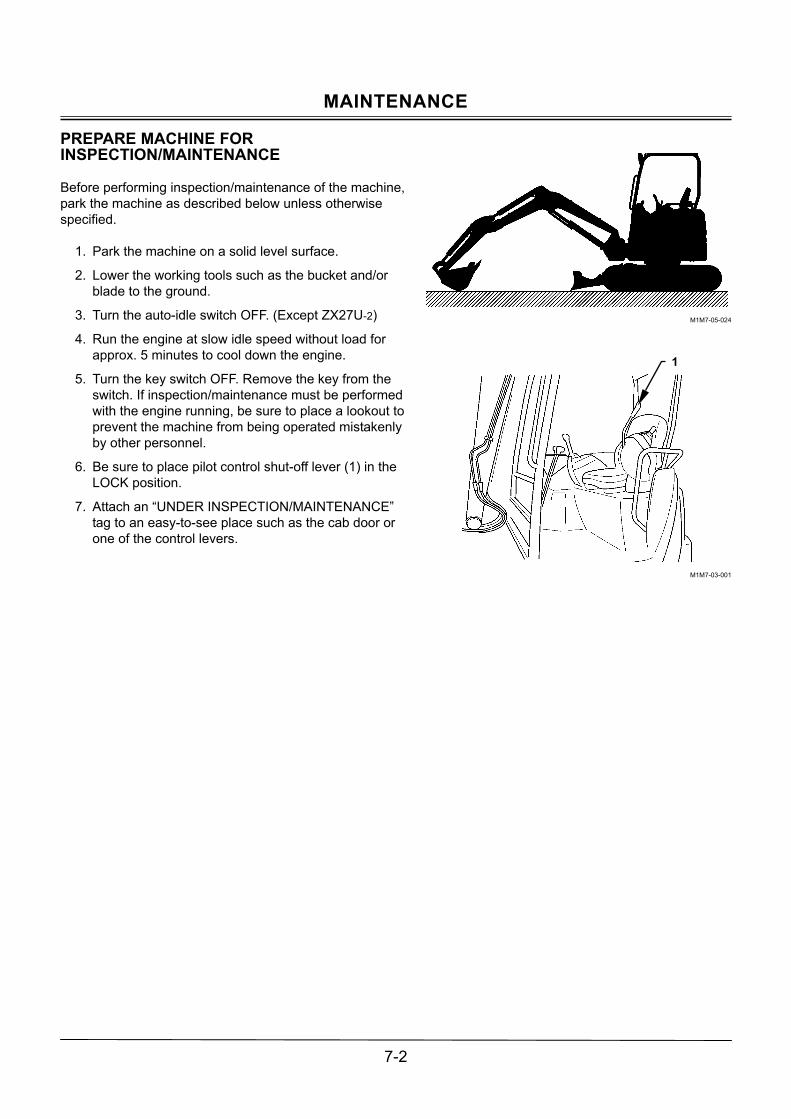
MAINTENANCE
7-2
PREPARE MACHINE FOR INSPECTION/MAINTENANCE
Before performing inspection/maintenance of the machine, park the machine as described below unless otherwise specified.
1. Park the machine on a solid level surface.
2. Lower the working tools such as the bucket and/or blade to the ground.
3. Turn the auto-idle switch OFF. (Except ZX27U-2)
4. Run the engine at slow idle speed without load for approx. 5 minutes to cool down the engine.
5. Turn the key switch OFF. Remove the key from the switch. If inspection/maintenance must be performed with the engine running, be sure to place a lookout to prevent the machine from being operated mistakenly by other personnel.
6. Be sure to place pilot control shut-off lever (1) in the LOCK position.
7. Attach an �UNDER INSPECTION/MAINTENANCE� tag to an easy-to-see place such as the cab door or one of the control levers.
M1M7-05-024
M1M7-03-001
1

MAINTENANCE
7-3
OPENING/CLOSING ENGINE ACCESS COVERS
CAUTION: � Do not keep the engine access covers open
when the machine is parked on a slope, or while the wind is blowing hard. The engine ac-cess covers may close accidentally, possibly resulting in personal injury.
� When opening/closing the engine access cov-ers, take care not to allow your fingers to be become pinched with the covers.
Pull up latch (2) to open cover (1). The cover is raised by link mechanism (3). Be sure to fully raise the cover. After checking that stopper (4) provided on the left link is placed in LOCK position (5), remove your hand from the cover. Cover (1) will be locked in place. When closing cover (1), while raising cover (1), push stopper (4) at the arrowed position ! to disengage the lock. While pushing stopper (4), lower the cover. When the cover is lowered by the 1/4 stroke, leave stopper (4). Then, lower cover (1) further to completely close it. Be sure to com-pletely remove your hand, which is pushing stopper (4), out of cover (1) at this time. Failure to do so may cause your hand to be caught with cover (1), possibly resulting in se-vere injury.
M1M7-07-008
M1M7-07-009
M1M7-07-010
M1M7-07-069
1
2
3
4
5
4 5
Lock Position

MAINTENANCE
7-4
OPENING/CLOSING TANK COVERS
CAUTION: � Do not keep the tank cover open when the
machine is parked on a slope, or while the wind is blowing hard. The tank cover may close ac-cidentally, possibly resulting in personal injury.
� When opening/closing the tank cover, take care not to allow your fingers to be pinched with the cover.
1. Press button (2) and raise cover (1) to open cover (1).
Cover (1) will be stopped opening with wire (3).
2. Take stopper (4) out of holder (5). Install stopper (4) into lock hollow (6). Cover (1) is held in position.
3. When closing cover (1), follow the reverse order of the above procedure.
NOTE: Button (2) can be locked with key (7).
M1MF-07-030
M1MH-07-003
M1M7-07-018
M1M7-07-019
ZX27U-2, ZX30U-2, ZX35U-2
M1M7-07-001
ZX40U-2, ZX50U-2
3
1
45 6
2 1
3 4
5
61
Unlock Position
Lock Position
7
2 2
7
ZX40U-2、ZX50U-2
Unlock Position Lock
Position
2
7
2
7
ZX27U-2、ZX30U-2、ZX35U-2

MAINTENANCE
7-5
DAILY INSPECTION
M1M7-07-059
Checkpoint Engine 1. Quantity and contamination of engine oil and coolant
2. Ease of engine starting, exhaust gas color, abnormal noises 3. Oil and coolant leaks. Damage to hoses and pipes 4. Clogging of or damage to radiator/oil cooler 5. Loose or missing nuts and bolts
Upperstructure 1. Fuel level, leak, and contamination of foreign material 2. Hydraulic oil level, leaks, and contamination of foreign material 3. Control lever stroke, lever play, operating force 4. Operating condition of hydraulic components, damage to and oil leaks in hoses and pipes 5. Damage to or deformation of components and structures, abnormal noises 6. Loose or missing nuts and bolts
Undercarriage 1. Loose track sag, and wear on or damage to track components and structures 2. Wear on upper/lower rollers, front idlers, and oil leaks 3. Oil leaks from travel devices 4. Loose or missing nuts and bolts
Front Attachment 1. Damage to or oil leak from cylinders, hoses, and pipes 2. Damage to or wear on bucket and blade 3. Loose, worn or missing bucket teeth 4. Lubrication at greasing points 5. Damage to lock pins, stoppers, fastener rings and lock bolts for front joint pins 6. Loose or missing nuts and bolts
Miscellaneous 1. Malfunction of gauges, switches, lights, buzzer 2. Deformation of or damage to canopy 3. Abnormalities in machine appearance
NOTE: The operator must perform the daily inspection before operating the machine.
Arm Cylinder
Boom
Canopy
Swing Bearing
Swing Device
Battery
Hydraulic Oil Tank
Full Flow Filter
Suction Filter
Radiator, Oil Cooler
Center Joint
Muffler
Engine
Engine Oil Filter
Track
Pump Counterweight
Control Valve
Arm
Bucket Cylinder
Link B
Link A
Bucket
Side Cutter
Tooth
Work Light
Boom Cylinder
Control Lever
Blade Cylinder
Blade
Front Idler
Travel Device
Lower RollerUpper Roller
Track AdjusterTrack Frame
Fuel Filter
Water Separator
Pilot Filter
Fuel Tank
Boom Swing Cylinder
Solenoid Valve
Actuator

MAINTENANCE
7-6
PERIODIC REPLACEMENT OF PARTS
To ensure safe and long trouble free operation, be sure to conduct periodic inspections of the machine. In addition, the parts as listed below are directly related to safety op-eration so that they are recommended to be periodically replaced. These part material properties will change due to aging, or repeated operation may cause deterioration, wear, and/or fatigue of these parts, possibly resulting in serious safety/fire hazards. It is very difficult to gauge the remaining service lifetime of these parts simply by visual inspection alone. For this reason, replace these parts at the intervals shown in the table below. If any of these parts are found to be defective by inspection, immediately replace it regard-less of the recommended intervals. Consult your nearest Hitachi dealer for correct replace-ment.
Periodic Replacement Parts Replacement Interval Fuel hose (Fuel tank to filter) Every 2 years or 4000 hours Fuel hose (Fuel tank to injection pump) Every 2 years or 4000 hours Heater hose (Heater to engine) Every 2 years or 4000 hours Engine rubber vibration insulator Every 5 years or 3000 hours Floor mount rubber Every 5 years or 3000 hours
Engine
Pump coupling Every 5 years or 3000 hours Pump suction hose Every 2 years or 4000 hours Pump delivery hose Every 2 years or 4000 hours Swing hose Every 2 years or 4000 hours Auxiliary hose Every 2 years or 4000 hours
Base Machine
Oil cooler hose (C/V to oil cooler) Every 2 years or 4000 hours Boom cylinder line hose Every 2 years or 4000 hours Arm cylinder line hose Every 2 years or 4000 hours Bucket cylinder line hose Every 2 years or 4000 hours
Hydraulic System
Front Attachment
Pilot hose Every 2 years or 4000 hours NOTE: When replacing a hose, be sure to replace seals, such as O-rings and gaskets, along with the hose.

MAINTENANCE
7-7
MAINTENANCE GUIDE
A. GREASING (See Page 7-11) Interval (hours) Parts Quantity
8 50 100 250 500 1000 20001. Front Joint Pins (Incl. around the swing post) 9 ! !! 2. Bucket and Link Pins 5 ! 3. Blade Pins 4 4. Swing Bearing 1 5. Swing Internal Gear 1 6. Control Lever Universal Joint 2 NOTE: ! Grease all submerged pins after operating in water.
Grease all pins daily during break-in operation for 50 hours. !! Grease all pins every 100 hours only during first time operation up to 500 hours.
B. ENGINE (See Page 7-17) Intervals (Hours) Parts Quantity
8 50 100 250 500 1000 2000Oil Level Check �
ZX27U-2, ZX30U-2, ZX35U-2
7.2 L (1.9 US gal)
1. Engine oil
ChangeZX40U-2, ZX50U-2
8.6 L (2.27 US gal)
!
2. Replacement of engine oil filter 1
C. TRANSMISSION (See Page 7-19) Interval (hours) Parts Quantity
8 50 100 250 500 1000 2000Oil Level Check �
ZX27U-2, ZX30U-2, ZX35U-2
0.6 L (0.63 US qt)×2 1. Travel Reduction
Gear Change ZX40U-2, ZX50U-2
0.9 L (0.95 US qt)×2
D. HYDRAULIC SYSTEM (See Page 7-21) Interval (hours) Parts Quantity
8 50 100 250 500 1000 20001. Check Hydraulic Oil Level 1 2. Drain Hydraulic Oil Tank Sump 1
ZX27U-2, ZX30U-2, ZX35U-2
58 L (15.3 US gal) 3, Change Hydraulic Oil
ZX40U-2, ZX50U-285 L
(22.5 US gal)
! !
4. Clean Suction Filter 1 When changing hydraulic oil 5. Replace Full Flow Filter Element 1 !! 6. Replace Pilot Filter Element 1
for leaks or looseness � 7. Check Hoses and Lines for cracks, bend, etc. �
NOTE: ! Hydraulic oil changing intervals differ according to kind of hydraulic oils used. See recommended oil chart.
!! For the first time only.

MAINTENANCE
7-8
E. FUEL SYSTEM (See Page 7-36)
Fuel tank capacity: ZX27U-2, ZX30U-2 and ZX35U-2: 40L, ZX40U-2 and ZX50U-2: 70L Interval (hours) Parts Quantity
8 50 100 250 500 1000 20001. Check Water Separator 1 2. Drain Fuel Tank Sump 1 As needed 3. Replace Fuel Filter 1
for leaks, cracks, etc. − 4. Check Fuel Hoses for cracks, bend, etc. − NOTE: The fuel filter may become clogged earlier than normal due to contaminated fuel. In case the engine
power is reduced, or black smoke increases, shorten the intervals of inspection/maintenance.
F. AIR CLEANER (See Page 7-40)
Interval (hours) Parts Quantity 8 50 100 250 500 1000 2000Cleaning 1 ! Or clogged 1. Air Cleaner Element Replacement 1 After cleaning 6 times or 1 year
NOTE: ! Shorten the interval in a dusty work site.

MAINTENANCE
7-9
G. COOLING SYSTEM (See Page 7-41)
Interval (hours) Parts Quantity 8 50 100 250 500 1000 2000
1. Check Coolant Level 1 2. Check and Adjust Fan Belt Tension 1 !!
ZX27U-2, ZX30U-2, ZX35U-2
6.0 L (1.6 US gal) 3. Change Coolant
ZX40U-2, ZX50U-26.6 L
(1.7 US gal)
Once every two years (in autumn) or 2000 hours
Outside 1 ! 4. Clean Radiator Core Interior 1 When changing coolant NOTE: ! Shorten maintenance interval in dusty work site.
!! For the first time only. NOTE: When genuine Hitachi long life coolant (LLC) is used, replace it every two years(in autumn) or after
2000 operating hours, whichever comes first. IMPORTANT: Use fresh water or tap water for the coolant. Avoid using strong acid or alkaline water. Be
sure to use genuine Hitachi long life coolant (LLC).
H. ELECTRICAL SYSTEM (See Page 7-46)
I. MISCELLANEOUS (See Page 7-50)
Interval (hours) Parts Quantity8 50 100 250 500 1000 2000
1. Check Bucket Teeth � 2. Replace Bucket 1 As required 3. Check Track Sag (rubber crawler) and damage 2 4. Replace Rubber Crawler 2 As required 5. Check Track Sag (steel crawler) (Optional) 2 6. Check and Replace Seat Belt 1 Every 3 years (Replace) 7. Check bucket hook (Optional) 8. Check air conditioner (Cab Equipped Machine)
Clean 9. Clean and Replace Air Conditioner Circulation Filter. Replace Replace after cleaning approx. 6 times.
10. Clean Cab Floor � As required 11. Check Fuel Injection Nozzles � ♦ 12. Check and Adjust Value Clearance � ♦ 13. Check Injection Timing � ♦ 14. Measure Engine Compression Pressure � ♦ 15. Check Starter and Alternator � ♦ 16. Check Radiator Cap � ♦ 17. Check Tightening Torque of Bolts and Nuts � !! NOTE: Consult your nearest Hitachi dealer for inspection/maintenance of items with mark♦. The recom-
mended oil chart is affixed on the tank access cover. ★★ For the first time only.

MAINTENANCE
7-10
THE BRAND NAMES OF RECOMMENDED OILS AND LUBRICANTS
Grease Engine Oil Gear Oil Air Temp
Manufacturer
�20 to 40°C (�6 to 104°F)
�20 to 0°C (�6 to 32°F)
�10 to 35°C(14 to 95°F)
25 to 40°C (77 to 104°F)
�20 to 40°C (�6 to 104°F)
For New Ma-chine
Japan Energy Resonic EP Grease 2
Yanmar Genuine Engine Oil Super Royal (CD) 10W-30
ZX27U-2/30U-2/35U-2 Apoll oil diesel motive CD-S
ZX40U-2/50U-2 Mitsubishi Diamond Hypoid Gear oil 90
BP Vanellus C3 British Petro-leum
BP Energrease LS-EP2 10W 30 40
BP Gear oil SAE 90 EP
RPM DELO 300 C3 Caltex Oil Multifax EP2 10W 30 40
Universal Thuban SAE 90
Essolube D-3 Esso Beacon EP2 10W 30 40
Esso Gear oil 90
Apoll oil diesel motive S-310 S-330 S-340 Idemitsu Ko-
san Daphne coronex
grease EP2 (�15 to 40°C) (5 to 104°F) Apoll oil custom wide 15W-40 Apoll oil super wide 15W-40
Apoll oil gear HE90
Mobil Delvac Exxon Mobil Mobilux EP2 1310 1330 1340
Mobilube HD80W-90
Hi-diesel S3
Eneos Epinoc Grease Ap2
�20 to 35°C (�6 to 95°F)
10W-30
�10 to 40°C (14 to 104°F)
15W-40
Hypoid gear 90
Rymla D Shell Oil Shell Alvania EP Grease 2 10W 30 40
Shell Spirax EP 90
Remarks API CD CLASS API GL4 class
Hydraulic Oil Fuel Oil Change Interval 2000 hours 1000 hours
Air Temp
Manufacturer
�20 to 0°C (�6 to 32°F)
�10 to 40°C(14 to 95°F)
�20 to 0°C (�6 to 32°F)
�10 to 40°C (14 to 95°F)
Hitachi * Super EX 46 HN Malti M TOTAL Equivis ZS 46
Idemitsu Kosan Dephne Superhydro LW46H British Petroleum Bartran HV46
Caltex Oil Rando Oil HD46 Texaco INC. Rando Oil HD46
Chevron U.S.A INC Chevron AW46 Esso NUTO H46
Mobil Oil DTE 25
Shell Oil Tellus Oil S46 Tellus Oil R46
Use high quality Die-sel Fuel only. ASTM2-D (JIS K-2204) Kerosene must not be used.
NOTE: The machine shipped from the factory is filled with oil marked *.

MAINTENANCE
7-11
A. GREASING
Front Joint Pins (Incl. Swing Post Joint Pins) --- every 500 hours or every years (every 100 hours up to 500 hours of operation)
1. Position machine with the arm cylinder fully retracted
and the bucket cylinder fully extended. Lower bucket to the ground (the front attachment inspection posi-tion). All greasing points can be lubricated from the ground.
2. Grease all grease fittings illustrated below.
(1) Boom cylinder rod end
(2) Boom cylinder bottom
M1M7-05-024
M1M7-07-020
M1M7-07-021
M1M7-07-070 ZX40U-2, ZX50U-2
ZX27U-2, ZX30U-2, ZX35U-2

MAINTENANCE
7-12
(3) Boom foot
(4) Arm cylinder rod end and bucket cylinder bottom
(5) Boom and arm joint pin, and arm cylinder bottom
M1M7-07-022
M1M7-07-058
M571-07-006
M585-07-046
ZX27U-2、ZX30U-2、ZX35U-2
ZX40U-2、ZX50U-2

MAINTENANCE
7-13
(6) Swing cylinder
(7) Swing post
M1M7-07-023
M1M7-07-024

MAINTENANCE
7-14
Bucket and Link Pins --- every 100 hours Grease all submerged pins after operating in water.
Blade Pins --- every 500 hours or every year
� Blade connecting pin
� Blade cylinder rod end and bottom
Precautions for Front Attachment and Blade Re-moval
1. When pins are removed to replace the front attach-ment or blade, do not attempt to clean the bore in-sides of the bushings.
2. Before installing the front attachment or the blade, apply grease sufficiently to the pin-boss ends or the dust seals of the cylinders.
3. Be sure to install at least one shim on both sides of front joint pins.
4. When the swing post is disassembled, coat the pins and the thrust plates with grease before reinstalling them.
M503-07-092
M1LA-07-037

MAINTENANCE
7-15
Swing Bearing --- every 250 hours
CAUTION: Before lubricating the swing bearing, lower the bucket and the blade to the ground, stop the engine, and place the pilot control shut-off lever to the LOCK position. Lubrication and rotation of the upperstructure must be done by one person only. Be sure to check that no per-sonnel are present around the machine before starting to work.
Grease via grease fitting (1).
1. Lower the bucket and the blade to the ground, stop
the engine, and place the pilot control shut-off lever to the LOCK position. Add grease with a grease gun by two to three strokes. Lower the bucket and blade to the ground.
2. Raise the bucket approx. 200 mm (8 in) above the ground. While rotating the upperstructure, add grease in 8 places at approximately every 90° in-terval until the upperstructure is made two turns.
M1M7-07-025

MAINTENANCE
7-16
Swing Internal Gear --- every 500 hours
CAUTION: Before lubricating the swing bearing, lower the bucket and the blade to the ground, stop the engine, and place the pilot control shut-off lever to the LOCK position. Lubrication and rotation of the upperstructure must be done by one person only. Be sure to check that no personnel are present around the machine before starting to work.
1. Remove the cover from the bottom center of the
undercarriage. Check if grease inside is cloudy due to mixing of water or dirt.
2. Apply grease via grease fitting (1) by the quantity shown in the table
3. In order to apply grease evenly to the swing gear, raise the bucket approximately 200 mm (8 in) above the ground. While swinging the upperstruc-ture at approximately 90° intervals until one full turn is made, add grease at each interval.
Greasing Quantity
Total Grease Capacity
ZX27U-2 ZX30U-2 ZX35U-2
0.2 L (0.21 US qt)
3.0 to 3.3 L (3.1 to 3.5 US qt)
ZX40U-2 ZX50U-2
0.2 L (0.21 US qt)
3.2 to 3.5 L (3.4 to 3.7 US qt)
Control Lever Universal Joint --- every 500 hours or yearly
Pull up the rubber boots under the right and left control levers, remove two screws (1) to remove bracket (2). After moving the rubber boots upward, add grease to the four places of the pilot valve pushers as indicated by arrows.
M1M7-07-025
M1M7-07-026
M1M7-07-016
1
2

MAINTENANCE
7-17
B. ENGINE
Engine Oil --- Level check daily (Check before starting the engine.)
Check the oil level every day before starting the machine. Oil level must be between the marks on oil level gauge (1). If necessary, add the specified en-gine oil via oil filler (2). Re-check the oil level after refilling.
Change Engine Oil --- every 500 hours
Replace Engine Oil Filter --- every 500 hours
CAUTION: Each component of the engine may be hot immediately after operation. Allow com-ponents to cool before starting to work on them.
1. Prepare a 10-liter (2.6 US gal) container to receive
the drain oil.
2. Remove drain plug (2) from engine oil pan (1) to drain the oil.
3. Allow oil to drain through a clean cloth to check if any debris such as small pieces of metal are pre-sent on the cloth.
4. After all oil has drained, re-Install and tighten drain plug (2).
Wrench size : 19 mm Tightening torque : 88 N⋅m (9 kgf⋅m, 65 lbf⋅ft)
M1M7-07-027
M1M7-07-028
M104-07-010
M1M7-07-029
12
Oil Pan
Clean Cloth
Container
1 2

MAINTENANCE
7-18
5. Remove oil filter (3) from the engine by turning it counterclockwise using a filter wrench. The oil may spill from the filter bottom bracket at this time. Use an empty container to catch the spilled oil.
6. Coat the gasket of new filter (3) with engine oil. Turn the filter clockwise by hand until the gasket touches the sealing surface.
7. Tighten oil filter (3) 3/4 turns more using the filter wrench. Take care if oil filter (3) may become de-formed if excessively tightened.
NOTE: Tightening torque: 19.6 to 23.5 N⋅m (2.0 to 2.4 kgf⋅m, 14.5 to 17 lbf⋅ft)
8. Remove oil filler cap (4). Refill the engine.
NOTE: Refer to the recommended oil and grease chart on page 7-10 for the brand names of oils.
9. Check that oil level is between the upper and lower limit marks on the dipstick. Start the engine.
10. Check that no oil is leaking from the sealing joints.
11. Run the engine at slow idle for 5 minutes. Stop the engine. After 15 minute later, recheck the oil level. Add as needed.
NOTE: Do not re-use the engine oil filter (3).
M1M7-07-030
M1M7-07-031
3
5 4

MAINTENANCE
7-19
C. TRANSMISSION
Travel Reduction Gear
CAUTION: � Each component of the travel reduction gear
may be hot immediately after operation. Allow components to cool before starting to work on them.
� The travel reduction gear may be pressurized. Be sure to release the internal pressure by slowly loosen the air bleed plug two to three turns before removing the plug. Failure to do so may cause the plug and/or gear oil to fly out, possibly resulting in personal injury. Keep body and face away from the air bleed plug.
Check Oil Level --- every 250 hours
1. Park the machine on a level surface.
2. Rotate the travel motor until plugs are positioned as illustrated on the right. Stop the engine.
3. Slowly loosen plug (1) to release pressure.
4. Remove plugs (1 and 2). Check that oil flows out of the thread hole for plug (2). If no oil flows out, add oil until oil flows out of the plughole.
5. After cleaning plugs (1 and 2), wrap the plug threads with sealing-type tape. Install the plugs (1 and 2). Tightening torque: 29 to 39 N⋅m (3 to 4 kgf⋅m, 21.5 to 29 lbf⋅ft).
M503-07-015
M585-07-080
1
2
1
2

MAINTENANCE
7-20
Change Gear Oil --- every 1000 hours
1. Park the machine on a level surface.
2. Rotate the travel motor until plugs are positioned as illustrated on the right. Stop the engine.
3. Slowly loosen plug (1) to release pressure.
4. Remove drain plug (3) and plug (1) to drain oil.
5. After draining oil completely, clean plug (3). Wrap the threads of plug (3) with sealing-type tape. Install plug (3).
Tightening torque: 29 to 39 N⋅m (3 to 4 kgf⋅m, 21.5 to 29 lbf⋅ft).
6. Supply oil through the thread hole for plug (1).
NOTE: Refer to the recommended oil and grease chart on page 7-10 for the brand names of oils.
7. Remove plug (2). Add oil until oil flows out of the tread
hole for plug (2).
Oil Quantity ZX27U-2, ZX30U-2, ZX35U-2 0.6 L (0.63 US qt) ZX40U-2, ZX50U-2 0.9 L (0.95 US qt)
8. After cleaning plugs (1 and 2), wrap the threads of the
plugs with sealing-type tape. Reinstall the plugs. Tightening torque: 29 to 39 N⋅m (3 to 4 kgf⋅m, 21.5 to 29 lbf⋅ft).
M585-07-080
1
2
3

MAINTENANCE
7-21
D. HYDRAULIC SYSTEM
Inspection and Maintenance of Hydraulic Equipment
CAUTION: When inspecting and/or maintaining hydraulic equipment, pay special attention to the following points.
1. Be sure to park the machine on a level, solid surface.
2. Lower the bucket and blade to the ground and stop the engine.
3. Begin servicing hydraulic components only after the components, hydraulic oil and lubricants are com-pletely cooled, and after releasing residual pressure.
3.1 Bleed air pressure from the hydraulic oil tank. 3.2 Each component, hydraulic oil, and lubricant may
be hot and/or pressurized immediately after opera-tion. Allow the machine to cool down before begin-ning inspection or maintenance. Failure to do so may cause burns caused by contact with hot component and/or oil, or injury by contacting flying off of plugs and /or screws. Hydraulic components may be pressurized even when cooled. Keep body parts and face away from plugs or screws and slowly loosen them. Remove plugs and screws only after thoroughly releasing the residual pres-sure.
3.3 Never attempt to service or inspect the travel and swing motor circuits on slopes. Even after air pressure is released from the hydraulic oil tank, the machine on a slope will create force to pressurize hydraulic oil in the travel and swing circuit by its own weight.
IMPORTANT:
1. Take special care to keep seal surfaces of hy-draulic components free from dirt and to avoid damaging them.
(1) Wash hoses, pipes, tank and their sur-rounding areas with a washing liquid and thoroughly wipe it out before reconnecting them.
(2) Only use O-rings that are free of damage or defects. Never carelessly file O-ring seat surfaces. Do not allow high pressure hoses to twist when connecting them. Failure to do so may considerably shorten the service life of the hoses.
2. Do not use hydraulic oils other than those listed in the table �Brand names of recom-mended hydraulic oil�. When adding hydraulic oil, always use the same brand of oil. Do not mix brands of oil. When selecting to use an-other brand of oil, be sure to completely re-place the oil in the system.
3. Never run the engine without oil present in the hydraulic oil tank.

MAINTENANCE
7-22
Check Hydraulic Oil Level --- daily
1. Park the machine on a solid level surface. Position
the machine with the arm cylinder fully retracted and the bucket cylinder fully extended. Lower the bucket and blade to the ground. Stop the engine.
2. Check oil level gauge (1) on the side of the hydraulic oil tank. Oil must be at the specified level on the gauge.
M1M7-05-024
M1M7-07-032
M1M7-03-004
1
1 ZX27U-2, ZX30U-2, ZX35U-2
ZX40U-2, ZX50U-2

MAINTENANCE
7-23
Drain Hydraulic Oil Tank Sump --- every 250 hours
CAUTION: Be sure to work only after oil tem-perature is low or before operation. Failure to do so may allow high temperature oil to spray, pos-sibly causing severe burns.
1. Park the machine on a solid level surface. Position
the machine with the arm cylinder fully retracted and the bucket cylinder fully extended. Lower the bucket and blade to the ground. Stop the engine.
2. Leave the machine without operating the machine until hydraulic oil becomes cool. Then, bleed air pressure from the hydraulic oil tank.
3. Slowly loosen drain plug (1) on the bottom of the hy-draulic oil tank to drain water and sediment.
M1M7-05-024
M1M7-07-033
1

MAINTENANCE
7-24
Change Hydraulic Oil --- every 1000 hours or 2000 hours
CAUTION: Be sure to work only after oil tem-perature is low or before operation. Failure to do so may allow high temperature oil to spray, pos-sibly causing severe burns.
IMPORTANT: When changing hydraulic oil, take care
not to allow foreign matter such as dirt, water or soil to enter the hydraulic sys-tem. Hydraulic oil changing intervals differ according to kind of hydraulic oil used.
1. Park the machine on a solid level surface. Position
the machine with the arm cylinder fully retracted and the bucket cylinder fully extended. Lower the bucket and blade to the ground. Stop the engine.
2. Remove the cover above the hydraulic oil tank. Loosen filler cap (1) on the hydraulic oil tank to re-lease air pressure from the hydraulic oil tank.
3. Remove cap (1).
4. Arrange a container with the capacity (A). Drain oil using a suction pump.
Oil Quantity (A) ZX27U-2, ZX30U-2, ZX35U-2 60 L (15.9 US gal) ZX40U-2, ZX50U-2 90 L (23.8 US gal)
M1M7-05-024
M1M7-07-035
M1M7-07-036
1
1
ZX27U-2, ZX30U-2, ZX35U-2
ZX40U-2, ZX50U-2

MAINTENANCE
7-25
5. Slowly loosen drain plug (2) on the bottom of the hy-draulic oil tank. Allow oil to drain thoroughly
6. Clean, install and tighten drain plug (2) to the original position.
ZX27U-2 ⋅ ZX30U-2 and ZX35U-2 Wrench Size : 12 mm (PT3/8 Square Head Plug) Tightening Torque : 49 N⋅m (5 kgf⋅m, 36 lbf⋅ft)
ZX40U-2 and ZX50U-2 Wrench Size : 27 mm (G1/2 Hexagonal Head
Plug with O-ring) Tightening Torque : 95 N⋅m (9.7 kgf⋅m, 70 lbf⋅ft)
7. Supply hydraulic oil via the filler port on the top of the hydraulic oil tank while checking the oil level with level gauge (3).
M1M7-07-033
M1M7-07-034
M1M7-03-004
2
3
3 ZX27U-2, ZX30U-2, ZX35U-2
ZX40U-2, ZX50U-2

MAINTENANCE
7-26
Bleed Air from Hydraulic System
After changing hydraulic oil, bleed air from the hydraulic system by following the procedure described below. Bleed Air from Pump
IMPORTANT: If the engine is started when the pump is not filled with hydraulic oil, damage to the pump may result.
1. Connect all hydraulic lines to the hydraulic pump. Fill
any hydraulic components, that can be filled with hy-draulic oil, with as much hydraulic oil as possible at this time.
2. Add hydraulic oil to the hydraulic oil tank to the speci-fied level.
3. Check all line connections for any oil leaks. Set the engine control dial in the slow idle position.
4. Start the engine. Wait 5 to 10 seconds. Stop the en-gine.
5. Check the hydraulic oil level at the level gauge lo-cated on the side of the hydraulic oil tank. Add hy-draulic oil if necessary.
6. Restart the engine. Confirm that hydraulic oil level in the hydraulic oil tank is sufficient. Run the engine for approximately 1 minute.
7. This is the end of the hydraulic pump air bleeding procedure.
NOTE: If the hydraulic pump is left empty overnight or
longer, be sure to fill the pump with clean hy-draulic oil before performing the air bleeding procedure above.
Bleed Air from hydraulic circuits
1. After filling hydraulic oil in the hydraulic oil tank, start the engine. Evenly operate each cylinder and swing motor repeatedly for 10 to 15 minutes to purge air from hydraulic system.
2. Position the machine in the hydraulic oil level check-ing position.
3. Stop the engine. Check hydraulic oil level. Add oil as necessary.
M589-07-010
M1M7-07-032
M1LD-07-006
M1M7-03-004
ZX27U-2, ZX30U-2, ZX35U-2
ZX40U-2, ZX50U-2
Oil Filter
Oil Filter
1
ZX27U-2, ZX30U-2, ZX35U-2
ZX40U-2, ZX50U-2

MAINTENANCE
7-27
Clean Suction Filter--- when changing hydraulic oil
The suction filter is located on the bottom side in the hy-draulic oil tank. Clean the suction filter when changing hydraulic oil. 1. After draining hydraulic oil, remove cover (1). Take
care not to allow the O-ring to come off cover (1) at this time.
2. Remove suction filter (4) together with rod (3).
3. Clean the hydraulic oil tank interior and the suction filter.
4. Install suction filter (4) together with rod (3) to the suction pipe.
5. Install cover (1) so that rod (3) is securely inserted into support (2) on cover (1).
6. Secure cover (1) with four bolts.
Wrench Size : 13 mm Tightening Torque : 49 N⋅m (5 kgf⋅m, 36 lbf⋅ft)
ZX27U-2, ZX30U-2, ZX35U-2
M1M7-07-002
M1M7-07-003
ZX40U-2, ZX50U-2
1
2
3
4
1
2
3
4

MAINTENANCE
7-28
Replace Full Flow Filter --- every 500 hours (first time after 250 hours)
CAUTION: Be sure to work only after oil tem-perature is low or before operation. Failure to do so may allow high temperature oil to spray, pos-sibly causing severe burns.
1. Park the machine on a solid level surface. Position
the machine with the arm cylinder fully retracted and the bucket cylinder fully extended. Lower the bucket and blade to the ground. Stop the engine.
2. Before replacing the element, be sure to loosen the hydraulic oil tank cap to release the air pressure from the hydraulic oil tank.
3. Loosen four bolts (1) to remove cover (2) and O-ring (3). While pressing cover (2) down, slowly remove cover (2) so that spring (4) doesn�t fly out.
4. Remove spring (4), valve (5) and element (6).
5. Take care not to allow water and/or dirt to enter the filter case.
6. Be careful not to damage element (6) and O-ring (3). Don�t use a broken element.
7. Install new element (6), and O-ring (3) in the hydraulic oil tank
8. Install cover (2) with four bolts (1). Tightening torque: 49 N⋅m (5 kgf⋅m, 36 lbt⋅ft)
9. After replacing the element, bleed air from the pump. Check the oil level in the hydraulic oil tank. (Refer to
�Bleed Air from Hydraulic System.�) If the ma-chine is operated without completely bleeding air from the hydraulic system, damage to the pump may re-sult.
10. Replace the element at the specified interval to keep hydraulic oil clean and extend the service life of hy-draulic components.
M1M7-05-024
M1M7-07-004
1 2 3
4
5
6

MAINTENANCE
7-29
Replace Pilot Filter --- every 1000 hours
1. Park the machine on a solid level surface. Position
the machine with the arm cylinder fully retracted and the bucket cylinder fully extended. Lower the bucket and blade to the ground. Stop the engine.
2. Before replacing the element, be sure to loosen the hydraulic oil tank cap to release the air pressure from the hydraulic oil tank.
3. Remove bolts (3) to remove under cover (2) from the rear left bottom side of the base machine.
Wrench size: 17 mm
M1M7-05-024
M1M7-07-035
M1M7-07-037
M1M7-07-071
1
3
2

MAINTENANCE
7-30
4. Rotate the hexagon section on the bottom of filter case (6) counterclockwise using a tool such as a wrench to remove filter case (6) from head cover (5).
5. While rotating filter element (7), pull to remove filter element (7) downward.
6. Replace O-ring (8) with a new one.
7. Securely install O-ring (8) in the O-ring groove on head cover (8).
8. Coat the seal on new filter element (7) with clean hy-draulic oil. Completely install filter element (7) into fil-ter head (4) while rotating filter element (7) taking care not to damage the filter element.
9. Take care not allow dust and/or water enter the filter case.
10. Install case (6) into head cover (5) while rotating the case clockwise. Tightening Torque: 25 to 34 N⋅m (2.5 to 3.5 kgf⋅m), 18.0 to 25.5 lbf⋅ft)
11. After replacing the filter element, bleed any remaining air from the hydraulic circuit while running the engine at a slow speed for approx. 3 minutes.
12. Check the oil level in the hydraulic oil tank. Add oil as needed.
13. Install under cover (2).
14. Tighten the hydraulic oil tank cap.
M1M7-07-072
M503-07-031
M1M7-07-032
M1M7-03-004
5
8
7
6
ZX27U-2, ZX30U-2, ZX35U-2
ZX40U-2, ZX50U-2
4

MAINTENANCE
7-31
Check Hoses and Lines --- daily --- every 250 hours
CAUTION: � Escaping flammable fluid may cause fire.
Check for missing or loose clamps, kinked hoses, lines or hoses that rub against each other and/or come in contact with other components, and any oil leaks.
� Escaping fluid under pressure can penetrate the skin causing serious injury. To avoid this hazard, search for leaks with a piece of cardboard. Take care to protect hands and body from high-pressure fluids. If an accident occurs, see a doctor familiar with this type of injury immediately.
� Repair or replace any missing, loose or damaged clamps, hoses, and lines.
� Do not bend or strike high-pressure lines. � Never install bent or damaged hoses or lines.
Check hoses and lines for oil leaks and/or damage while referring to the following tables. If any abnormality is found, repair it as instructed in the remedy column.
SA-031
SA-292
SA-044
Hoses Interval (Hours)
Check Point Abnormality Remedy
Daily Hose surface Hose end Hose connection
Oil leak (1) Oil leak (2) Oil leak (3)
Replace Replace Retighten or replace hose or O-ring
Every 250 hours
Hose surface Hose end Hose surface Hose surface Hose Hose and hose fitting
Oil leak (4) Oil leak (5) Exposed reinforcement (6) Blister (7) Acute bend (8), Collapse (9) Deformation or Corrosion (10)
Replace Replace Replace Replace Replace Replace
M137-07-008
M115-07-145
1
2
3
23
3 2
1
2
3

MAINTENANCE
7-32
Lines Interval (Hours)
Check Point Abnormality Remedy
Daily Flange type fitting mating face and connection bolt Weld joint surface on flange type fitting
Oil leak (11) Looseness or oil leak (11) Oil leak (12)
Replace Replace O-ring and/or retighten bolt Replace
Every 250 hours
Flange type fitting neck Weld joint surfaces On flange type fitting Clamp
Crack (13) Crack (12) Omission Deformation Loose
Replace Replace Replace Replace Retighten
Oil cooler Interval (Hours)
Check Point Abnormality Remedy
Every 250 hours
Hose and hose connection Oil cooler
Oil leak (14) Oil leak (15)
Retighten or replace Replace
M115-07-146
M117-07-147
M117-07-148
M117-07-149
M137-07-001
M137-07-007
M155-07-049
15
14
1213
1112
13
9
10
8
7
8
4
5

MAINTENANCE
7-33
Hose Fitting
• Metal Face Seal Fittings (Width Across Flats of Union Nut: 17, 19, 22, and 27 mm)
Fittings are used on smaller size hoses. Metal flare seat (4) on adapter (1) and metal flare (5) on hose (2) ends seal pressure oil. Precaution for Application Take care not to damage flare seat (4) and flare (5) when disconnecting or connecting them. Tightening Torque Tighten adapter (1) and nut (3) to the torque values shown in the table below.
±10% Width across flats (mm) 17 19 22 27
N⋅m 24.5 29.5 39 64 (kgf⋅m) (2.5) (3) (4) (6.5)Tightening
torque (lbf⋅ft) (18) (21.5) (29) (47)
• Pipe Metal Seal Fitting (Width Across Flats of Union Nut: 17)
Metal flare seat (4) on adapter (1) and metal flare (5) on pipe (2) ends seal pressure oil. Precaution for Application Take care not to damage flare seat (4) and flare (5) when disconnecting or connecting them. Tightening Torque Tighten adapter (1) and nut (3) to the torque values shown in the table below.
Width across flats (mm) 17 N⋅m 39
(kgf⋅m) (4) Tightening torque
(lbf⋅ft) (29)
M202-07-051
M1M7-07-005
1 4 3 5 2
1 4 5 3 2

MAINTENANCE
7-34
• Flat Face O-ring Seal Fitting (ORS Fitting) O-ring (1) is used on the end face of adapter (2) to prevent oil leakage between the joints. Precautions for Application
1. Replace O-ring (1) with a new one when
re-assembling fittings.
2. Before tightening union nut (4), check that O-ring (1) is correctly seated in O-ring groove (3). If union nut (4) is tightened when O-ring is not correctly seated in O-ring groove (3), damage to O-ring (1) and oil leak from fittings may result.
3. Take care not to make dents on O-ring groove (3) of adapter (2) and seal face (4) on the hose or valve side (5) when re-assembling fittings. Failure to do so may cause damage to O-ring (1) and oil leak from fittings.
4. If oil leaks from a loose connection of union nut (4), open the connection, replace O-ring (1), and check that the O-ring is correctly seated in O-ring groove (3) before re-tightening the connection.
Tightening Torque Tighten adapter (1) and union nut (4) to the torque values shown in the table below
±10%
Width across flats (mm) 19 22 24 27 N⋅m 44 74 78 103
(kgf⋅m) (4.5) (7.5) (8.0) (10.5)Fastening torque
(lbf⋅ft) (32.5) (55) (57.5) (76)
M104-07-033
2 6 1 4 5
63

MAINTENANCE
7-35
Quick Coupler
1. Connection Procedure
1.1 While pulling and fully turning socket ring (1) counterclockwise, insert socket ring (1) onto plug (7) until the end face of socket ring (1) comes in contact with plug (7).
1.2 Release socket ring (1). Check that socket ring (1) is slightly moved backward by the spring force and that the coupler is held in position with balls (2). Be sure to check that socket ring (1) has been moved back fully to the right original position.
2. Disconnection Procedure
2.1 While pulling and fully turning socket ring (1) counterclockwise, disconnect the coupler. As no check valve is provided in the coupler, take care that oil may flow out of the coupler when the coupler is disconnected.
2.2 After the coupler is disconnected, plug the holes with the exclusively prepared plugs.
IMPORTANT: � Take care not to damage the joint surfaces
when disconnecting or connecting the coupler.
� Before disconnecting or connecting the coupler, clean the coupler and its surroundings with a cleaning solvent and completely wipe off the cleaning solvent. Use extra care not to allow foreign matter such as dirt to enter the coupler.
� Disconnect or connect the coupler in the correct procedure. Confirm by inspection that no oil leak is present after connecting the coupler.
� After connecting the coupler, check that that socket ring (1) has been moved back fully to the right original position.
M1M7-07-006
7 8 1 4 3
6 2 5

MAINTENANCE
7-36
E. FUEL SYSTEM
CAUTION: Fuel is highly flammable. Handle fuel with care. Keep open flame or sparks away from fuel.
Refueling
After parking the machine on a level surface, check the fuel level with fuel gauge (1) and level gauge (2). When necessary to add fuel, remove fuel tank cap (3) and refill fuel.
NOTE: Even though the key switch is OFF, the fuel
level can be checked by pressing and holding display selector (5) for longer than 0.5 seconds. As long as display selector (5) is kept pressed, the fuel level is displayed. As soon as the switch is released, the display disappears.
1. To avoid condensation, fill the tank at the end of each
day�s operation. Take care not to add more fuel than the specified level.
Fuel Tank Capacity ZX27U-2, ZX30U-2, ZX35U-2 40 L (10.6 US gal) ZX40U-2, ZX50U-2 70 L (18.5 US gal)
2. After refilling fuel, close tank cover (4). Be sure to lock
the cover to prevent vandalism.
NOTE: Take care not to allow water and/or dirt to enter the fuel system when refilling fuel.
Bleed Air from Fuel System
Air in the fuel system will cause the engine to start hard and/or run roughly. Be sure to bleed air from the system after replacing the fuel filter or draining the tank.
Automatic bleeding device is provided on this machine. 1. Confirm that the fuel level is more than one-half of the
tank capacity. If the fuel level is lower, automatic bleeding device will not operate. Add fuel.
2. Turn the key switch ON and hold for 10 to 15 seconds.
3. Start the engine and check the fuel system for fuel leaks.
ZX27U-2
M1M7-01-031
ZX30U-2, ZX35U-2 ZX40U-2, ZX50U-2
M1M7-01-028
M1M7-07-039
M1M7-03-004
ZX40U-2, ZX50U-2
ZX27U-2, ZX30U-2, ZX35U-2
3
4
2
3
2
4
5 5
1 1

MAINTENANCE
7-37
Check Water Separator --- daily
When water is accumulated in water separator (2), Loosen drain plug (3) to drain water and sediment. If water is difficult to drain, loosen air bleed plug (4).
Drain Fuel Tank Sump --- as required
Park the machine on a solid level surface. Loosen bolts (5) to remove drain valve cover (6) from right-front cover (7). Rotate drain valve cover (6) to open the checking port. Open drain valve (1) on the bottom of the fuel tank and allow the water and sediments to drain from the fuel tank sump.
M1M7-07-040
M1MF-07-032
M1MF-07-033
4
2
3
7 5
6
1

MAINTENANCE
7-38
Replace Fuel Filter --- every 500 hours
1. Close stop valve (1).
2. Remove fuel filter (2) with a fuel filter wrench.
3. Clean the mounting surface for fuel filter (2).
4. Install new fuel filter (2) while rotating the fuel filter clockwise until the fuel filter comes in contact with the mounting surface. Tighten the fuel filter about 1/2 turns more using the filter wrench.
NOTE: Tightening torque: 11.8 to 15.6 N⋅m (1.2 to 1.6 kgf⋅m, 9 to 11.5 lbf⋅ft)
5. Open stop valve (1).
6. Turn the key switch ON and hold for 10 to 15 seconds.
7. Start the engine and check the fuel system for fuel leaks.
M1M7-07-040
M1M7-07-007
Tighten
Loosen
1
2

MAINTENANCE
7-39
Check Fuel Hoses --- daily --- every 250 hours
CAUTION: � Escaping fuel may cause fire. Check for kinked
hoses, or hoses that rub against each other and/or come in contact with other components, and any oil leaks.
� Repair or replace any loose or damaged hoses.
� Never install accurately bent or damaged hoses.
Check hoses for oil leaks and/or damage while referring to the following tables. If any abnormality is found, repair it as instructed in the remedy column.
Hoses Interval (Hours) Check Point Abnormality Remedy Daily Hose fittings
Soutache braid hose surface
Leak (1) Rubbed marks (2)Crack (2)
Retighten or replace Replace Replace
Every 250 hours
Soutache braid Hose surface Hose fittings Hose Hose ends and fittings
Crack (3) Crack (4) Acute bend (5) Collapse (6) Corrosion (7)
Replace Replace Replace Replace Replace
M137-07-003
M137-07-004
M137-07-005
M137-07-006
1 2
1
3
4
5
6
7

MAINTENANCE
7-40
F. AIR CLEANER
Clean the Air Cleaner Element --- every 250 hours or when the air cleaner indicator comes ON. Replace the Air Cleaner Element --- after cleaning six times or after one year
Clean and replace air cleaner element.
1. Before servicing element (1), be sure to stop the engine.
CAUTION: Be sure to wear safety glasses or goggles before removing cover (3).
2. Loosen two clamps (2) to remove cover (3) and
element (1).
CAUTION: Wear safety glasses or goggles when using compressed air pressure [less than 0.2 MPa (2 kgf/cm2, 29 psi)].
IMPORTANT:
� Clean cover (3) to prevent dirt or water from entering the air cleaner suction port. If water enters the air cleaner suction port, damage to the engine may result.
� When cleaning, don�t hit element (1) or force the element to collide against other object.
3. Clean element (3) by blowing compressed air pressure [less than 0.2 MPa (2 kgf/cm2, 29 psi)] from the inside of the element. After cleaning, be sure to check element (1) for damage. If any damage is found, replace the element with a new one.
4. If air filter indicator (5) comes ON immediately after cleaning the element even though cleaning is less than six times, replace the element with a new one.
5. When installing cover (3), position the cover so that valve (4) faces downward. Then, tighten the cover with clamps (2) in the specified position.
M555-07-023
M1M7-07-041
ZX27U-2, ZX30U-2, ZX35U-2
M1M7-07-042
ZX40U-2, ZX50U-2
1
2
5
4
3
2
5
4
32
4
2
5
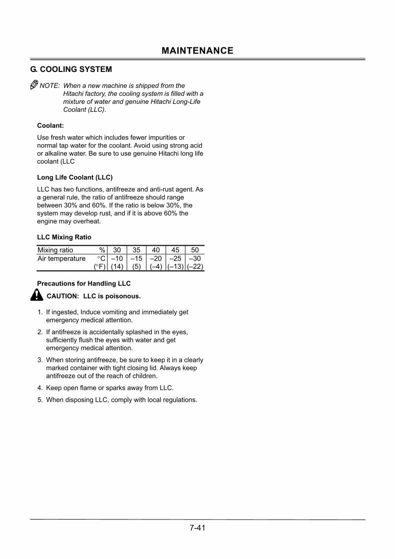
MAINTENANCE
7-41
G. COOLING SYSTEM
NOTE: When a new machine is shipped from the Hitachi factory, the cooling system is filled with a mixture of water and genuine Hitachi Long-Life Coolant (LLC).
Coolant:
Use fresh water which includes fewer impurities or normal tap water for the coolant. Avoid using strong acid or alkaline water. Be sure to use genuine Hitachi long life coolant (LLC Long Life Coolant (LLC)
LLC has two functions, antifreeze and anti-rust agent. As a general rule, the ratio of antifreeze should range between 30% and 60%. If the ratio is below 30%, the system may develop rust, and if it is above 60% the engine may overheat. LLC Mixing Ratio
Mixing ratio % 30 35 40 45 50Air temperature °C (°F)
�10 (14)
�15 (5)
�20 (�4)
�25(�13)
�30(�22)
Precautions for Handling LLC
CAUTION: LLC is poisonous.
1. If ingested, Induce vomiting and immediately get emergency medical attention.
2. If antifreeze is accidentally splashed in the eyes, sufficiently flush the eyes with water and get emergency medical attention.
3. When storing antifreeze, be sure to keep it in a clearly marked container with tight closing lid. Always keep antifreeze out of the reach of children.
4. Keep open flame or sparks away from LLC.
5. When disposing LLC, comply with local regulations.

MAINTENANCE
7-42
Check Coolant Level --- daily
Check that the coolant level is between the FULL and LOW marks on coolant reservoir (2). If the coolant level is below the low mark, remove the reservoir cap and add coolant to coolant reservoir (2).
CAUTION: Do not loosen radiator filler cap (1) unless the system is cool. Hot steam may escape, possibly causing severe burns. Loosen the cap slowly to the stop after the coolant becomes cool. Release all pressure before removing the cap.
If coolant reservoir (2) is empty, add coolant through radiator cap (1).
M1M7-07-043
ZX27U-2, ZX30U-2, ZX35U-2
M1M7-07-044
ZX40U-2, ZX50U-2
2
1
1
2
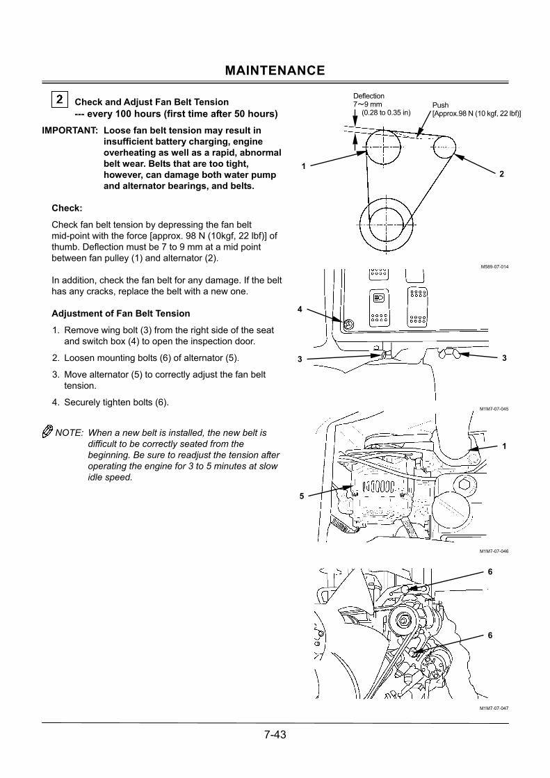
MAINTENANCE
7-43
Check and Adjust Fan Belt Tension --- every 100 hours (first time after 50 hours)
IMPORTANT: Loose fan belt tension may result in insufficient battery charging, engine overheating as well as a rapid, abnormal belt wear. Belts that are too tight, however, can damage both water pump and alternator bearings, and belts.
Check:
Check fan belt tension by depressing the fan belt mid-point with the force [approx. 98 N (10kgf, 22 lbf)] of thumb. Deflection must be 7 to 9 mm at a mid point between fan pulley (1) and alternator (2). In addition, check the fan belt for any damage. If the belt has any cracks, replace the belt with a new one. Adjustment of Fan Belt Tension
1. Remove wing bolt (3) from the right side of the seat and switch box (4) to open the inspection door.
2. Loosen mounting bolts (6) of alternator (5).
3. Move alternator (5) to correctly adjust the fan belt tension.
4. Securely tighten bolts (6).
NOTE: When a new belt is installed, the new belt is
difficult to be correctly seated from the beginning. Be sure to readjust the tension after operating the engine for 3 to 5 minutes at slow idle speed.
M589-07-014
M1M7-07-045
M1M7-07-046
M1M7-07-047
Deflection 7~9 mm
(0.28 to 0.35 in) Push [Approx.98 N (10 kgf, 22 lbf)]
21
3
4
1
5
6
3
6

MAINTENANCE
7-44
Change Coolant --- every two years or 2000 hours
NOTE: In case genuine Hitachi Long-Life Coolant is
used, change the coolant every two years (in autumn every other year), or every 2000 hours, whichever comes first.
CAUTION: Do not loosen the radiator cap unless the system is cool. Hot steam may escape, possibly causing severe burns. Loosen the radiator cap slowly to the stop after the coolant becomes cool. Release all pressure before removing the cap.
Procedure of Coolant Change
1. Remove the radiator cap. Open drain cock (1) on the radiator and drain the drain valve on the water jacket to allow the coolant to drain completely. Drain impurities such as water scale at the same time.
2. Close radiator drain cock (1) and the drain valve on the water jacket. Fill the radiator with fresh water including less impurity or normal tap water and a radiator cleaner agent. Start the engine and run it at a speed slightly higher than slow idle to raise the coolant temperature until the needle of the temperature gauge reaches the white zone. Then, run the engine further for about ten minutes.
3. Stop the engine and open radiator drain cock (1) to allow the coolant to drain. Flush out the cooling system with fresh water including less impurity or normal tap water, until draining water becomes clear. This helps remove water scale.
4. Close radiator drain cock (1). Fill the radiator with fresh water which includes fewer impurities or normal tap water and LLC at the specified mixing ratio. When adding coolant, do so slowly to avoid mixing air bubbles in the system. Run the engine to sufficiently bleed the air from the cooling system.
5. After adding coolant, operate the engine for several minutes. Check the coolant level again, and add coolant if necessary.
M1M7-07-048
M1M7-07-049
M1M7-07-050
M1M7-07-051
1
1
ZX40U-2, ZX50U-2
ZX27U-2, ZX30U-2, ZX35U-2
ZX27U-2, ZX30U-2, ZX35U-2
ZX40U-2, ZX50U-2

MAINTENANCE
7-45
Clean Radiator --- every 500 hours
CAUTION: Always wear safety glasses or goggles when using compressed air [less than 0.2 MPa (2 kgf/cm2, 29 psi)] to clean radiator core.
IMPORTANT:
� Cover air cleaner inlet opening to prevent entry of dust and water while cleaning the radiator.
� High-pressure air [less than 0.2 MPa (2 kgf/cm2, 29 psi)] or water can damage radiator fins. Keep the pressure nozzle 500 mm (19.7 in) or more away from the core face.
The radiator and the oil cooler are arranged in series. In case dust or dirt should become stuck to the radiator core, clean the radiator with compressed air and/or water to maintain the cooling ability of the cooling system.

MAINTENANCE
7-46
H. ELECTRICAL SYSTEM
IMPORTANT: � Improper radio communication equipment and
associated parts, and/or improper installation of radio communication equipment effects the machine�s electronic parts, causing involuntary movement of the machine. Also, improper installation of electrical equipment�s may cause machine failure and/or a fire on the machine. Be sure to consult your nearest Hitachi dealer when installing s radio communication equipment or additional electrical parts, or when replacing electrical parts.
� Never attempt to disassemble or modify the electrical/electronic components. If replacement is required, consult your nearest Hitachi dealer.
Battery
CAUTION: Battery generates explosive gas during operation or charge. Keep sparks and flames away from battery. Do not continue to use or charge the battery when the electrolyte level is lower than specified. Explosion of the battery may result. Charge battery in a well-ventilated area. Sulfuric acid in battery electrolyte is poisonous. It is strong enough to burn skin, eat holes in clothing, and cause blindness if splashed into eyes.
IMPORTANT: If the battery is used with the electrolyte
level lower than the specified low level, the battery may deteriorate quickly.
IMPORTANT: Don�t refill electrolyte more than the
specified upper level. Electrolyte may spill, damaging the painted surfaces and/or corroding other machine parts.
NOTE: In case electrolyte is refilled more than the
specified upper level line or beyond the bottom end of the sleeve, remove the excess electrolyte until the electrolyte level is down to the bottom end of the sleeve using a pipette. After neutralizing the removed electrolyte with sodium bicarbonate (Baking powder), flush with plenty of water, otherwise, consult the battery manufacturer.
SA-032
SA-036

MAINTENANCE
7-47
Electrolyte Level Check
1. Check the electrolyte level at least once a month.
2. Park the machine on level ground and stop the engine.
3. Check the electrolyte level.
3.1 When checking the level from the battery side: Clean around level check lines with a wet towel. Don�t use a dry towel. Static electricity maybe developed, causing the battery gas to explode. Check if the electrolyte level is between U.L (Upper level) and L.L (Lower level). In case the electrolyte level is lower than the middle level between the U.L and L.L, immediately refill distilled water or commercial battery fluid. Be sure to refill with distilled water before recharging (operating the machine). After refilling, securely tighten the filler plug.
3.2 When it is impossible to check the level from the battery side or no level check mark is indicated on the side: After removing the filler plug from the top of the battery, check the electrolyte level by viewing through the filler port. It is difficult to judge the accurate electrolyte level in this case. Check if the electrolyte surface touches the bottom end of the sleeve or not according to the right illustrations. When the electrolyte surface is lower than the bottom end of the sleeve, refill with distilled water or commercial battery fluid up to the bottom end of the sleeve. After refilling, securely tighten the filler plug.
3.3 When an indicator is available to check the level, follow its check result.
4. Always keep the vicinity around the battery terminals clean to prevent battery discharge. Check battery terminals for looseness and rust. Coat terminals with grease or petroleum jelly to the terminals to prevent corrosion.
M146-07-109
M146-07-110
M146-07-111
M146-07-112
M409-07-072
When the electrolyte surface is lower than the bottom end of the sleeve, the electrode ends are seen straight.
Since the electrolyte surface touches the bottom end of the sleeve, the electrolyte surface is raised due to surface tension so that the electrode ends are seen curved.
Lower Level Upper Level
Sleeve
Filler Port
Lower
L.L (Lower Level)
U.L (Upper Level)
Separator Top
Proper

MAINTENANCE
7-48
Check Electrolyte Specific Gravity
The specific gravity for electrolyte varies depending on electrolyte temperature. The specific gravity should be kept within the range shown below. Charge the battery if the specific gravity is below the limit.
Working Range of Electrolyte Specific Gravity
M104-07-054
NOTE: Check the specific gravity of electrolyte after it is cooled to air temperature. As electrolyte temperature changes immediately after operation, correct measurement can be difficult.
Precautions for Handling Batteries
� If electrolyte spills on your skin or clothes, immediately flush the spilled skin or clothes with water. Then, sufficiently wash them with soapy water. If electrolyte splashes in eyes, flush your eyes with water for 10 to 15 minutes. Get medical attention immediately.
� Don�t use fire hazards such as matches or tobacco, or don�t allow sparks to fly near the batteries.
� Perform battery maintenance only after turning the key switch OFF and removing the battery caps.
� Touching the batteries soon after operation is hazardous. Wait for the batteries to cool.
� During charging, batteries generate flammable hydrogen gas. Remove the batteries from the base machine. Then, charge the batteries in a well-ventilated area only after removing the caps.
� When disconnecting the battery terminals, be sure to disconnect the negative (ground) terminal first, and when reconnecting the battery terminals, reconnect the negative (ground) terminal last. If a conductor such as a metal tool is placed between the battery positive terminal and the vehicle frame with the battery negative terminal kept connected to the vehicle frame, electric short circuit may occur, possibly creating a hazardous situation.
� Loosely tightened terminals may cause sparks to fly. Securely tighten the terminals.
SA-032
SA-036
40℃
20℃
0℃
-40℃
Working Range
-20℃
1.21 1.22 1.23 1.24 1.25 1.26 1.27 1.28 1.29 1.30 1.31 1.32 1.33
Flui
d te
mp.
Specific gravity of battery fluid

MAINTENANCE
7-49
Replacing Fuses
1. If any electrical equipment fails to operate, first check the fuses in the fuse box.
2. One each capacity of spare fuses are provided in the fuse box.
M1M7-07-052
M1M7-07-076
Fuse Box

MAINTENANCE
7-50
I. MISCELLANEOUS
Check Bucket Teeth for Looseness and/or Wear --- daily
Check the bucket teeth for wear and looseness Replace teeth (1) if tooth wear exceeds the service limit shown below.
Dimension A in mm (in.) New Limit of Use
128 (5.0″) 65 (2.6″)
CAUTION: Guard against injury from flying pieces of metal. Use safety equipment such as a hard hat and safety glasses.
1. Use hammer (2) and drift (3) to drive out locking pin
(5). Be careful not to damage rubber pin lock (4) while removing locking pin (5).
2. Inspect locking pin (5) and rubber pin lock (4) for any damage. Replace short or damaged locking pins as illustrated below with new ones.
M104-07-056
M589-07-017
M104-07-118
M104-07-058
M104-07-059
4
WRONG WRONG
RIGHT
WRONG
5
Level the bottom surfaces. Lock pin length is too short.
1 4 5
2
3
Steel balls almost come off due to damage to the lock rubber.
Steel balls can be depressed by finger force.

MAINTENANCE
7-51
3. Clean shank (6) surface.
4. Install rubber pin lock (4) into shank (6) hole as shown.
M104-07-060
5. Position new tooth (1) over shank (6).
M104-07-061
6. Drive locking pin (5) fully into the hole as shown.
M104-07-062
1 5
6 1
6 4
RIGHT WRONG WRONG
WRONGWRONG
WRONGRIGHT
RIGHT

MAINTENANCE
7-52
Replace Bucket
CAUTION: When driving the connecting pins in or out, guard against injury from flying pieces of metal or debris; wear a hard hat, goggles or safety glasses, heavy gloves and safety equipment appropriate for the job.
Select a spacious job site with good footing. Start working only after ensuring the safety of other personnel around the machine. Avoid quick operation of the front attachment. Give the highest priority to safety when engaging in teamwork by strictly exchanging safety signs. Removal
1. Park the machine on a level surface. Lower the bucket to the ground and position it with the flat surface resting on the ground. Be sure the bucket will not roll when the pins are removed.
2. Slide the O-rings out of the specified position to the bucket boss side.
3. Remove bucket pins A and B to separate the arm and bucket.
Installation
1. Clean the removed pins and pin bores. Apply sufficient grease to the pins and pin bores.
2. Place a new bucket in a stabilized position.
3. Join the arm to hole A and the link to hole B with pins.
4. Securely install the lock washers to all pins.
5. Reinstall the sealing O-ring to the specified position.
6. Apply grease to all pin joints.
7. Start the engine and run it at slow idle. Slowly operate the bucket in both directions to check for any interference in bucket movement.
M104-07-063
O-Ring Shift
Bucket Boss Link
B
A
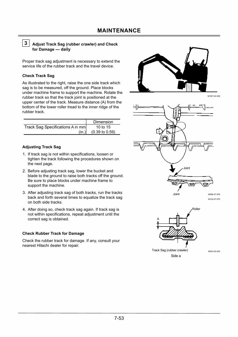
MAINTENANCE
7-53
Adjust Track Sag (rubber crawler) and Check for Damage --- daily
Proper track sag adjustment is necessary to extend the service life of the rubber track and the travel device. Check Track Sag
As illustrated to the right, raise the one side track which sag is to be measured, off the ground. Place blocks under machine frame to support the machine. Rotate the rubber track so that the track joint is positioned at the upper center of the track. Measure distance (A) from the bottom of the lower roller tread to the inner ridge of the rubber track. Dimension Track Sag Specifications A in mm (in.)
10 to 15 (0.39 to 0.59)
Adjusting Track Sag
1. If track sag is not within specifications, loosen or tighten the track following the procedures shown on the next page.
2. Before adjusting track sag, lower the bucket and blade to the ground to raise both tracks off the ground. Be sure to place blocks under machine frame to support the machine.
3. After adjusting track sag of both tracks, run the tracks back and forth several times to equalize the track sag on both side tracks.
4. After doing so, check track sag again. If track sag is not within specifications, repeat adjustment until the correct sag is obtained.
Check Rubber Track for Damage
Check the rubber track for damage. If any, consult your nearest Hitachi dealer for repair.
M1M7-04-006
M588-07-055
M102-07-075
M503-05-050
Joint
Joint
Roller
A
Track Sag (rubber crawler)
Side a

MAINTENANCE
7-54
Loosen Track (Rubber Crawler)
CAUTION: Do not loosen valve (1) too quickly or too much as high-pressure grease in the adjusting cylinder may spout out. Loosen carefully, keeping body parts and face away from valve (1). Never loosen grease fitting (2).
IMPORTANT: When gravel or mud is packed around
the components in the undercarriage, remove it before loosening valve (1).
1. To loosen track, slowly turn valve (1)
counterclockwise using a socket wrench (long socket 19); grease will escape from grease outlet.
2. Between 1 and 1.5 turns of valve (1) are sufficient to loosen track. Never attempt to loosen the valve further.
3. If grease does not drain smoothly, raise the track to be loosed off the ground and slowly rotate the track.
4. When proper track sag is obtained, turn valve (1) clockwise and tighten it to 88 N⋅m (9 kgf⋅m, 65 lbf⋅ft).
Tighten Track (Rubber Crawler)
CAUTION: In case the track sag is not adjustable, this is a very hazardous situation. Since the track adjuster spring is excessively loaded, the grease pressure inside the track adjuster cylinder is very high. Incorrect adjustment or disassembly may result in personal injury and/or death. Immediately consult your nearest Hitachi dealer for repair.
To tighten track, connect a grease gun to cylinder grease fitting (2) located inside the side frame and add grease until the sag is within specifications.
M1LA-07-012
M1LA-07-036
M1LA-07-036
2
1 Grease Outlet
2
1Grease Outlet
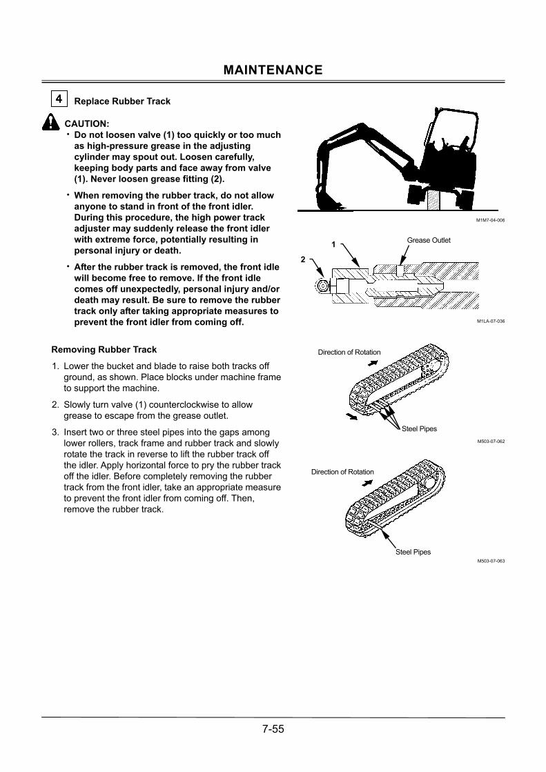
MAINTENANCE
7-55
Replace Rubber Track
CAUTION: � Do not loosen valve (1) too quickly or too much
as high-pressure grease in the adjusting cylinder may spout out. Loosen carefully, keeping body parts and face away from valve (1). Never loosen grease fitting (2).
� When removing the rubber track, do not allow anyone to stand in front of the front idler. During this procedure, the high power track adjuster may suddenly release the front idler with extreme force, potentially resulting in personal injury or death.
� After the rubber track is removed, the front idle will become free to remove. If the front idle comes off unexpectedly, personal injury and/or death may result. Be sure to remove the rubber track only after taking appropriate measures to prevent the front idler from coming off.
Removing Rubber Track
1. Lower the bucket and blade to raise both tracks off ground, as shown. Place blocks under machine frame to support the machine.
2. Slowly turn valve (1) counterclockwise to allow grease to escape from the grease outlet.
3. Insert two or three steel pipes into the gaps among lower rollers, track frame and rubber track and slowly rotate the track in reverse to lift the rubber track off the idler. Apply horizontal force to pry the rubber track off the idler. Before completely removing the rubber track from the front idler, take an appropriate measure to prevent the front idler from coming off. Then, remove the rubber track.
M1M7-04-006
M1LA-07-036
M503-07-062
M503-07-063
Direction of Rotation
Steel Pipes
Direction of Rotation
Steel Pipes
2
1 Grease Outlet

MAINTENANCE
7-56
Installing Rubber Track
1. Lower the bucket and blade to raise both tracks off ground. Place blocks under machine frame to support the machine.
2. Slowly turn valve (1) counterclockwise to allow grease to escape from the grease outlet.
3. Engage the rubber track with the sprocket and position the other end of the rubber track on the front idler.
4. While rotating the sprocket in reverse, apply horizontal force to the rubber track to seat it on the idler.
5. Insert a steel pipe into gaps among lower rollers, track frame and rubber track and rotate the rubber track slowly to correctly seat the rubber track on the idler.
6. Confirm that the rubber track is correctly engaged with the sprocket and idler.
7. Adjust track sag. (See page 7-53.)
8. After checking that the rubber track is correctly engaged with the sprocket and idler and the track sag is correctly adjusted, lower the machine to the ground.
M1LA-07-036
M503-07-062
M503-07-063
Direction of Rotation
Steel Pipes
Direction of Rotation
Steel Pipes
2
1 Grease Outlet

MAINTENANCE
7-57
Check Track Sag (steel crawler) --- every 50 working hours
Proper adjustment of track sag is vital to extending the service life of the track and travel device. Check Track Sag
As illustrated to the right, raise the one side track, which sag is measured, off the ground. Place blocks under machine frame to support the machine.
Dimension ZX27U-2 ZX30U-2 ZX35U-2
120 to 140(4.7 to 5.5)Track Sag
Specifications A in mm (in.) ZX40U-2
ZX50U-2 140 to 160(5.5 to 6.3)
NOTE: 1. Check track sag after thoroughly removing
soil stuck on track area by pressure washing. 2. When operating the machine on ground such
as mud or gravel, these materials may easily become packed into the undercarriage, adjust the track sag so that it is slightly loose.
Adjusting Track Sag
1. If track sag is not within specifications, loosen or tighten the track following the procedures shown on the next page.
2. When adjusting track sag, lower the bucket to the ground to raise one track off the ground. Repeat this procedure to raise the other track. Every time, be sure to place blocks under machine frame to support the machine.
3. After adjusting track sag of both tracks, move the machine back and forth several times to equalize the track sag on both side tracks.
4. After doing so, check track sag again. If track sag is not within specifications, repeat adjustment until the correct sag is obtained.
M1M7-04-006
M588-07-062
A
90 to 110 °

MAINTENANCE
7-58
Loosen Track (Steel Crawler)
CAUTION: Do not loosen valve (1) too quickly or too much as high-pressure grease in the adjusting cylinder may spout out. Loosen carefully, keeping body parts and face away from valve (1). Never loosen grease fitting (2).
IMPORTANT: When gravel or mud is packed around
the components in the undercarriage, remove it before loosening valve (1).
1. To loosen track, slowly turn valve (1)
counterclockwise using a socket wrench (long socket 19); grease will escape from grease outlet.
2. Between 1 and 1.5 turns of valve (1) are sufficient to loosen track. Never attempt to loosen the valve further.
3. If grease does not drain smoothly, raise the track to be loosed off the ground and slowly rotate the track.
4. When proper track sag is obtained, turn valve (1) clockwise and tighten it to 88 N⋅m (9 kgf⋅m, 65 lbf⋅ft).
Tighten Track (Steel Crawler)
CAUTION: In case the track sag is not adjustable, this is a very hazardous situation. Since the track adjuster spring is excessively loaded, the grease pressure inside the track adjuster cylinder is very high. Incorrect adjustment or disassembly may result in personal injury and/or death. Immediately consult your nearest Hitachi dealer for repair.
To tighten track, connect a grease gun to cylinder grease fitting (2) located inside the side frame and add grease until the sag is within specifications.
M1LA-07-013
M1LA-07-036
M1LA-07-036
2
1 Grease Outlet
2
1 Grease Outlet

MAINTENANCE
7-59
Converting the Track
CAUTION: � Consult your nearest authorized dealer for
converting the track. Extremely strong force is being applied. Do no allow anyone to stand in front of the front idler.
� After the rubber track is removed, the front idle will become free to remove. If the front idle comes off unexpectedly, personal injury and/or death may result. Be sure to remove the rubber track only after taking an appropriate measure to prevent the front idler from coming off.
Consult your nearest authorized dealer for converting the track. Change the track adjuster whenever converting the steel or rubber track.

MAINTENANCE
7-60
Check and Replace Seat Belt Check --- daily Replace --- every 3 years
Prior to operating the machine, thoroughly examine belt (1), buckle (2) and attaching hardware (3). If any item is damaged or materially worn, replace the damaged or worn item(s) before operating the machine. Replace seat belt (1) every three years regardless of its apparent condition. NOTE: The seat belt is optional on the machine
equipped with the 2-post canopy.
Check Bucket Hook (Optional) --- daily
Perform lifting work only after checking hook (1) for wear, cracks, and deformations, the hook joint for cracks, and rope guide (2) (latch, spring, pin, and spring pin) for damage and malfunction.
M1M7-07-012
M107-07-129
2
1
Hook
Spring
Spring Pin
Latch Pin
2 1
3

MAINTENANCE
7-61
Check Air Conditioner (Machine with Cab) --- daily
CAUTION: If refrigerant splashes into eyes or spills onto skin, blindness or cold contact burn may result. Never loosen the refrigerant circuit parts.
Check for refrigerant leaking from the pipe joints.
If an oil seepage mark is found at the pipe joints illustrated to the right, the refrigerant is possibly leaking.
Check the refrigerant level.
After operating the air conditioner in the cooling mode for 2 to 3 minutes with the engine running at 1500 min-1, check the refrigerant level through sight glass (inspection window) (2) on receiver dryer (1). Check the condenser.
If the condenser surface is contaminated with foreign matter such as dust or dead insects, cooling performance may be reduced. Keep the condenser clean. (Refer to the descriptions for Clean Radiator in INSPECTION AND MAINTENANCE section.) Check the compressor.
After operating the air conditioner for 5 to 10 minutes, touch both high and low pressure pipe lines with your hands. Normally, the high pressure side should be hot and the low pressure side should be cool. Check each bolt for looseness.
Check that the compressor mounting bolts and all other tightening bolts are securely tightened. Check the compressor belts and fan belts.
Check all belts for looseness and/or wear. If any faulty is found, consult your nearest Hitachi dealer for receiving detailed inspection.
M1M7-07-057
M107-01-050
M1M7-07-013
Tension Pulley
Compressor Pulley
Fan Pulley Depress [Approx. 98N (10 kgf, 22 lbf)]
Sag: 10 to 15 mm (0.39 to 0.59 in)
Alternator Pulley
Crank Pulley
2
1
Almost clear. A few bubbles may appear when the engine speed is raised or lowered.
Sufficient Quantity
Insufficient Quantity
No Refrigerant Empty

MAINTENANCE
7-62
Clean and Replace Air conditioner Re-circulation Filter
Clean Re-circulation Filter --- every 500 hours
Replace Re-circulation Filter--- after cleaning approx. 6 times
NOTE: The recommenced maintenance hour is a
reference value. In case the machine is operated in dusty job site, replace the filter at a shorter interval.
Removal of Re-circulation Filter
1. Remove floor mat (1). Remove bolts (3) to remove floor plate (2).
2. Grasp and pull the grips of re-circulation filters (4, 5, and 6) upright to remove them.
M1M7-07-055
M1M7-07-014
M1M7-07-015
M1M7-07-053
M1M7-07-054
1
3
4
5
6
2

MAINTENANCE
7-63
CAUTION: Always wear safety glasses or goggles when using compressed air.
Cleaning
Clean the re-circulation filter by blowing compressed air or with water. When cleaning the filter with water, follow the procedure below. 1. Clean the filter using tap water.
2. Hold the filter in water with a neutral detergent dissolved for about 5 minutes.
3. Clean the filter again with water.
4. Dry the filter.
Installation
Install the cleaned filters or new filters by following the removal procedure described on the previous page in the reverse order. � Insert filters (4 and6) into the grooves on both sides.
Install filter (5) into the center duct.
M1M7-07-053
M1M7-07-054
M1M7-07-055
4
5
6

MAINTENANCE
7-64
Clean Cab Floor--- as necessary
IMPORTANT: Only the cab floor can be washed with water. Take care not to splash other parts of the cab with water. Don�t increase the water pressure speed by squeezing the hose end. Never use steam to clean the cab floor. Always clean the cab floor only after closing ducts (1, 2, and 3) to prevent water from entering the duct. Failure to do so may result in malfunction of the air conditioner. If the box located under the seat is splashed with water, failure of the inside electrical parts may result.
1. Park the machine on a level surface. Lower the
bucket to the floor. Stop the engine.
2. Sweep the dust out of the cab floor and the pedals with a brush, or use a brush while directing water. (Sweep out the mud and bust with a brush as much as possible before applying water.)
3. When cleaning the floor mat, sweep out the dust and/or water along the grooves on the floor mat.
4. When cleaning the cab floor with the floor mat removed, remove only the rear mat. Then, sweep the dust and/or water through the steps.
5. In case the cab floor becomes seriously stained from using a lot of water when cleaning, check that no water has permeated into the air conditioner unit by removing the floor plates. In addition, clean the circulation air filter. If water permeation is recognized, run the blower at the maximum speed for several minutes until water drops disappear. Turn the air conditioner OFF at this time.
M1M7-07-073
1 2 3

MAINTENANCE
7-65
Check Injection Nozzle --- every 1000 hours
Consult your authorized dealer for inspection and repair
Check and Adjust Valve Clearance--- every 1000 hours
Consult your authorized dealer for inspection and repair
Check Injection Timing --- every 2000 hours
Consult your authorized dealer for inspection and repair.
Measure Engine Compression Pressure --- every 1000 hours
Consult your authorized dealer for inspection and repair.

MAINTENANCE
7-66
Check Starter and Alternator --- every 1000 hours
Consult your authorized dealer for inspection and repair.
Check Radiator Cap --- every 2000 hours
Consult your authorized dealer for inspection and repair.

MAINTENANCE
7-67
Check Tightening Torque of Bolts and Nuts (ZX27U-2, ZX30U-2, ZX35U-2) --- every 250 hours (first time after 50 hours)
Tighten or retighten all bolts and nuts to the torque values shown in the Table below. In addition, check bolts and nuts for looseness and omission. if any are loose or missing, be sure to retighten or supply new parts. Check tightness after the first 50 hours then every 250 hours.
Torque No. Descriptions Bolt Dia. mm Q�ty Wrench Size
mm N⋅m (kgf⋅m) (lbf⋅ft)1. Engine cushion rubber mounting bolt 12 4 19 88 (9) (65) 2. Engine bracket mounting bolt (Front) 10 8 17 49 (5) (36) 3. Hydraulic oil tank mounting bolt 12 4 19 88 (9) (65) 4. Fuel tank mounting nut 10 3 17 20 (2) (15)
7/16-20UNF 17 24.5 (2.5) (18) 19 29.5 (3) (22) 9/16-18UNF 22 39 (4) (29)
3/4-16UNF 27 93 (9.5) (69) 1-1/16-12UNF 36 175 (18) (129)
Metal face seal fitting for hydraulic hoses and piping
1-5/16-12UNF 41 205 (21) (151)9/16 UNF 19 44 (4.5) (32) 11/16 UNF 22 74 (7.5) (55)
5. Union joints for hydraulic hoses and pipes
ORS 13/16 UNF 27 103 (10.5) (76)
6. Pump mounting bolt 12 2 10 (Socket) 88 (9) (65) 7. Pump cover mounting bolt 10 8 17 49 (5) (36)
Control valve mounting bolt 10 4 17 49 (5) (36) 8. Control valve base mounting bolt 10 4 17 49 (5) (36) 9. Swing device mounting bolt 14 6 22 137 (14) (101)
10. Battery mounting nut 6 6 10 5 (0.5) (3.5)12 5 19 88 (9) (65) 11. Canopy mounting bolt 10 5 17 49 (5) (36) 12 5 19 88 (9) (65) 12. Cab mounting bolt 10 5 17 49 (5) (36)
Upperstructure 12 22 19 108 (11) (80) 13. Swing bearing mounting bolt Undercarriage 12 20 19 108 (11) (80)
14. Travel device mounting bolt 12 24 19 113 (11.5) (83) 15. Sprocket mounting bolt 12 24 19 113 (11.5) (83) 16. Upper roller mounting bolt 16 2 24 231 (23.5) (170)17. Lower roller mounting bolt 14 16 22 177 (18) (130)
6 10 5 (0.5) (3.5)8 13 9.8 (1) (7) 18. Cover mounting bolt 10 17 49 (5) (36)
19. Counterweight mounting bolt 22 2 32 540 (55) (398)10 17 49 (5) (36) 12 19 88 (9) (65) 14 22 137 (14) (101)16 24 205 (21) (152)
20. Front pin lock plate bolts
18 27 390 (40) (290)21. Side-cutter mounting bolts 14 6 22 175 (18) (130)22. Track roller guard mounting bolt 14 12 22 175 (18) (130)23. Tilt mechanism floor connection pins 10 1 17 49 (5) (36) 24. Tilt mechanism support-holding bolts 10 2 17 49 (5) (36) 25. Tilt mechanism support connection pins 8 1 13 9.8 (1) (7)
IMPORTANT: 1. Before installing, clean the bolt and nut threads to remove soil, rust, and/or dust. 2. When installing new bolts and/or nuts, apply lubricant (e.g. white zinc B solved into spindle oil) to
the screw threads. 3. Tighten bolts and nuts to the specifications. If tightened with excessively high or inadequate
torque, missing or breakage of bolts and/or nut may result. 4. In case the counterweight mounting bolts became loose, consult your nearest Hitachi dealer for
retightening.

MAINTENANCE
7-68
Check Tightening Torque of Bolts and Nuts (ZX40U-2, ZX50U-2) --- every 250 hours (first time after 50 hours)
Tighten or retighten all bolts and nuts to the torque values shown in the Table below. In addition, check bolts and nuts for looseness and missing parts. If any are loose or missing, be sure to retighten or supply new parts. Check tightness after the first 50 hours then every 250 hours.
Torque No. Descriptions Bolt Dia. mm Q�ty Wrench Size
mm N⋅m (kgf⋅m) (lbf⋅ft)1. Engine cushion rubber mounting bolt 12 4 19 88 (9) (65) 2. Engine bracket mounting bolt (Front) 10 8 17 49 (5) (36) 3. Hydraulic oil tank mounting bolt 12 4 19 88 (9) (65) 4. Fuel tank mounting nut 10 3 17 20 (2) (15)
7/16-20UNF 17 24.5 (2.5) (18) 19 29.5 (3) (22) 9/16-18UNF 22 39 (4) (29)
3/4-16UNF 27 93 (9.5) (69) 1-1/16-12UNF 36 175 (18) (129)
Metal face seal fitting for hydraulic hoses and piping
1-5/16-12UNF 41 205 (21) (151)9/16 UNF 19 44 (4.5) (32) 11/16 UNF 22 74 (7.5) (55)
5. Union joints for hydraulic hoses and pipes
ORS 13/16 UNF 27 103 (10.5) (76)
6. Pump mounting bolt 12 2 10 (Socket) 88 (9) (65) 7. Pump cover mounting bolt 10 8 17 49 (5) (36)
Control valve mounting bolt 10 4 17 49 (5) (36) 8. Control valve base mounting bolt 10 4 17 49 (5) (36) 9. Swing device mounting bolt 16 8 24 205 (21) (101)
10. Battery mounting nut 6 2 10 5 (0.5) (3.5)12 5 19 88 (9) (65) 11. Canopy mounting bolt 10 5 17 49 (5) (36) 12 5 19 88 (9) (65) 12. Cab mounting bolt 10 5 17 49 (5) (36)
Upperstructure 12 27 19 108 (11) (80) 13. Swing bearing mounting bolt Undercarriage 12 24 19 108 (11) (80)
14. Travel device mounting bolt 14 24 22 175 (18) (130)15. Sprocket mounting bolt 14 24 22 175 (18) (130)16. Upper roller mounting bolt 16 2 24 231 (23.5) (170)17. Lower roller mounting bolt 14 16 22 177 (18) (130)18. Track shoe bolt 12 312 19 137 (14) (101)
6 10 5 (0.5) (3.5)8 13 9.8 (1) (7) 19. Cover mounting bolt 10 17 49 (5) (36)
20. Counterweight mounting bolt 24 3 36 930 (95) (398)10 17 49 (5) (36) 12 19 88 (9) (65) 14 22 137 (14) (101)16 24 205 (21) (152)
21. Front pin lock plate bolts
18 27 390 (40) (290)22. Side-cutter mounting bolts 14 6 22 175 (18) (130)23. Track roller guard mounting bolt 16 12 24 265 (27) (196)24. Tilt mechanism floor connection pins 10 1 17 49 (5) (36) 25. Tilt mechanism support-holding bolts 10 2 17 49 (5) (36) 26. Tilt mechanism support connection pins 8 1 13 9.8 (1) (7)
IMPORTANT: 1. Before installing, clean the bolt and nut threads to remove soil, rust, and/or dust. 2. When installing new bolts and/or nuts, apply lubricant (e.g. white zinc B solved into spindle oil) to
the screw threads. 3. Tighten bolts and nuts to the specifications. If tightened with excessively high or low torque,
missing or breakage of bolts and/or nut may result. 4. In case the counterweight mounting bolts became loose, consult your nearest Hitachi dealer for
retightening.

MAINTENANCE
7-69
Tightening Torque Chart
Hexagon Head Bolt Socket Bolt
M552-07-091 M552-07-090
M552-07-092
Wrench Size Socket Bolt Wrench
Size
Nom
inal
Siz
e
mm
N⋅m (kgf⋅m) N⋅m (kgf⋅m) N⋅m (Kgf⋅m) mm N⋅m (kgf⋅m) mm 6 3,3 to 4.2 (0.3 to 0.4) 10 5 8 29.5 (3.0) 19.5 (2.0) 9.8 (1) 13 29.5 (3) 6 10 64 (6.5) 49 (5) 19.5 (2) 17 64 (6.5) 8 12 108 (11) 88 (9) 34 (3.5) 19 108 (11) 10 14 175 (18) 137 (14) 54 (5.5) 22 175 (18) 12 16 265 (27) 205 (21) 78 (8) 24 265 (27) 14 18 390 (40) 295 (30) 118 (12) 27 390 (40) 14 20 540 (55) 390 (40) 167 (17) 30 540 (55) 17 22 740 (75) 540 (55) 215 (22) 32 24 930 (95) 690 (70) 275 (28) 36 27 1370 (140) 1030 (105) 390 (40) 41 30 1910 (195) 1420 (145) 540 (55) 46 33 2550 (260) 1910 (195) 740 (75) 50 36 3140 (320) 2400 (245) 930 (95) 55

MAINTENANCE
7-70
Check Tilt Mechanism Fulcrum Bolts for Looseness.
Retighten tilt mechanism fulcrum bolts (1) every 250 hours of operation. After removing the right side operator�s seat cover, retighten bolts (1) to 49 N⋅m (5.0 kgf⋅m).
M1M7-07-074
1

MAINTENANCE
7-71
PREPARATION FOR INSPECTION AND MAINTENANCE
When the floor tilt mechanism is used: IMPORTANT: Do not open or close the floor tilt
mechanism in daily inspection. The daily inspection can be performed through the maintenance cover ports.
IMPORTANT: When using the floor tilt mechanism, consult your nearest Hitachi dealer. If bolts (3) are removed or installed by unauthorized personnel, mismatch to ROPS may occur.
When performing inspection and maintenance using the floor tilt mechanism, park the machine in the following procedure. 1. After operating the machine, wait the machine to
sufficiently cool. 2. Park the machine on solid and level surface. 3. Lower the blade on the ground. 4. After rolling the arm and the bucket in, lower the
bucket a wooden block down to the ground. 5. Face the front attachment straightforward toward the
machine without swinging the front attachment at this tame.
6. Stop the engine. Remove the key from the key switch. 7. Close the cab (optional) door. 8. After loosening two bolts (2) of cover (1) on the front
of the base machine, fully slide the cover upward. Then, temporarily tighten bolts (2) so that the cover does not fall.
9. Remove bolts (3) (not covered with resin caps) in the rear section of the operator�s seat.
CAUTION: Be careful. When bolts (3) are removed, the canopy or the cab may come off the floor.
CAUTION: Be careful that if the floor is tilted upward while raising the front attachment, the canopy or cab (optional) may come in contact with the boom.
M1M7-07-060
M1M7-07-061
M1M7-07-063
M1M7-07-064
Ground Level
1
2
3 3
Canopy Cab

MAINTENANCE
7-72
IMPORTANT: The operation torque of adjuster screw (4) shall be less than 24.5 N⋅m (2.5 kgf⋅m). In case the operating torque requires more than 24.5 N⋅m (2.5 kgf⋅m), bolts (3) may not be completely removed yet. Recheck whether all bolts (3) are completely removed.
10. Turn adjuster screw (4) to tilt canopy or cab assembly
(1) toward the front attachment.
Wrench size: 17 mm
11. Turn adjuster screw (4) clockwise until disc plate (5) on the side of the floor tilt mechanism is moved to the end of the floor tilt mechanism.
CAUTION: In case the cab is mounted, stop tilting the floor before the disc plate reaches the striped area. If the floor is tilted into the striped area, the cab may become unbalance so that it may fall downward, potentially creating hazardous conditions.
IMPORTANT: Don�t tilt the canopy or cab using other
than the floor tilt mechanism (such as a crane). Failure to do so may cause damage to the floor tilt mechanism and/or floor.
12. When working under the tilted floor, support the floor
opening section to ensure safety work.
M1M7-07-065
M1M7-07-066
M1MF-07-040
M1M7-07-067
4
5
4
2 or 4-Pillar Canopy
1
5
50 mm
4
Cab (Optional)

MAINTENANCE
7-73
TILTING FLOOR DOWN
CAUTION: Don�t quickly lower the floor. If the adjust screw (4) is quickly turned to lower the floor, the floor may severely vibrate, potentially creating hazardous conditions.
1. Slowly turn adjuster screw (4) counterclockwise.
Wrench size: 17 mm
2. Continue to turn adjuster screw (4) counterclockwise until the edge of bracket (13) comes in contact with bearing bracket (7).
CAUTION: If adjuster screw (4) is continuously turned after the floor is completely lowered, when the adjuster screw is extended by approx. 15 mm, washer (10) will come in contact with the end face of pin (11) so that adjuster screw (4) will not turn further. Take care that if adjuster screw (4) is forcibly turned further, deformation of washer (10) or missing of bolt (12) may result.
3. When the floor is completely lowered, adjuster screw
(4) will be extended. Adjust the clearance between flange (8) of adjuster screw (4) and contact face (9) to 2 to 5 mm.
M1M7-07-068
W1M9-01-05-002
M1M7-07-075
8
9
7
42 to 5 mm
12
11 10
13
49
8
2 to 5 mm

MAINTENANCE
7-74
4. Securely install the canopy or cab with three bolts (3).
Wrench size: 19 mm Tightening torque: 90 N⋅m (9.2 kgf⋅m)
CAUTION: Unless bolts (3) are tightened to the specification, the machine will not meet the standard of the Roll-Over Protective Structure (ROPS).
M1M7-07-063
M1M7-07-064
3Canopy
3 Cab

CONSUMABLE PARTS LIST
8-1
CONSUMABLE PARTS LIST
Filter Element (ZX27U-2, ZX30U-2, ZX35U-2) ZX27U-2 ZX30U-2, ZX35U-2
Full Flow Filter 4129280 ←
Hydraulic Oil Suction Filter 4617512 ←
Pilot Filter 4294130 ←
Engine Oil Filter 4626337 4641043
Fuel Filter 4626336 ←
Water Separator 4632694 ←
Air Cleaner Element 4417516 ← Filter Element (ZX40U-2, ZX50U-2) Full Flow Filter 4129280
Hydraulic Oil Suction Filter 4617512
Pilot Filter 4294130
Engine Oil Filter 4641043
Fuel Filter 4626336
Water Separator 4632694
Air Cleaner Element 4417516

CONSUMABLE PARTS LIST
8-2
Bucket Parts (ZX27U-2, ZX30U-2, ZX35U-2)
ZX27U-2 ZX30U-2, ZX35U-2
Part No. Quantity Part No. Quantity
Tooth 4339865 3 4339865 4
Lock Pin 4339868 3 4339868 4
Tooth
Lock Rubber 4339867 3 4339867 4
Side Cutter (R) 4626441 1 4626441 1
Side Cutter (L) 4626442 1 4626442 1
Bolt J921440 6 J921440 6
Spring Washer A590914 6 A590914 6
Side Cutter
Nut J950014 6 J950014 6
O-ring 4275520 (4) 4275533 (4)
Shim 4354262 2 4354260 2 Bucket Parts (ZX40U-2, ZX50U-2) Part No. Quantity
Tooth 4339865 4
Lock Pin 4339868 4
Tooth
Lock Rubber 4339867 4
Side Cutter (R) 4622021 1
Side Cutter (L) 4626430 1
Bolt 4317650 6
Spring Washer A590914 6
Side Cutter
Nut J950014 6
O-ring 4291436 (4)
Shim 4354258 2
NOTE: The quantities shown in the above tables are
those required for the one standard bucket. The quantities for an optional bucket may differ. The figures in ( ) in the O-ring columns include the O-ring quantities used at the joints between the arm and the link. Shims are used to adjust the clearance at the joint between the arm and bucket.

MAINTENANCE UNDER SPECIAL ENVIRONMENTAL CONDITIONS
9-1
MAINTENANCE UNDER SPECIAL ENVIRONMENTAL CONDITIONS
Operating Conditions Precautions for Maintenance
Muddy Soil, Rainy or Snowy
Weather
Before Operation: Check the tightness of plugs and all drain cocks. After Operation: Clean the machine and check for cracks,
damaged, loose or missing bolts and nuts. Lubricate all necessary part without delay.
Near the Ocean
Before Operation: Check the tightness of plugs and all drain cocks. After Operation: Thoroughly clean the machine with fresh water to
wash off salt. Service electrical equipment often to prevent corrosion.
Dusty Atmosphere
Air Cleaner: Clean the element regularly, at shorter service intervals.
Radiator: Clean the oil cooler screen to prevent clogging of the radiator core.
Fuel System: Clean the filter element and strainer regularly, at shorter service intervals.
Electrical Equipment: Clean them regularly, in particular, the commutator surface of the alternator and starter.
Rocky Ground
Tracks: Carefully operate while checking for cracks, damage and loose bolts and nuts. Loosen the tracks a little more than usual.
Front Attachment: Standard attachment may be damaged when digging rocky ground. Reinforce the bucket before using it, or use a heavy duty bucket.
Freezing Weather
Fuel: Use high quality fuel suitable for low temperature. Lubricant: Use high quality low viscosity hydraulic oil and
engine oil. Engine Coolant: Be sure to use antifreeze. Battery: Fully charge the batteries regularly with shorter
service intervals. If not charged fully, electrolyte may freeze.
Tracks: Keep the tracks clean. Park the machine on a hard surface to prevent the tracks from freezing to the ground.
Falling Stones
Cab: Provide a cab guard to protect the machine from falling stones when necessary.
High Ground (Altitudes:
Higher than 1500 m
(4900 ft))
Engine oil: Change at 1/2 normal service intervals. Engine oil filter: Replace at 1/2 normal service intervals. ※ When the machine is operated at the altitudes of 2000 m (6600 ft)or
higher, the ignition of the engine may be deteriorate, possibly resulting in significant reduction in durability or function. In case the machine is unavoidably operated under these conditions, consult your nearest Hitachi dealer in advance.

MAINTENANCE UNDER SPECIAL ENVIRONMENTAL CONDITIONS
9-2
MEMO
.....................................................................................................................................................................................
.....................................................................................................................................................................................
.....................................................................................................................................................................................
.....................................................................................................................................................................................
.....................................................................................................................................................................................
.....................................................................................................................................................................................
.....................................................................................................................................................................................
.....................................................................................................................................................................................
.....................................................................................................................................................................................
.....................................................................................................................................................................................
.....................................................................................................................................................................................
.....................................................................................................................................................................................
.....................................................................................................................................................................................
.....................................................................................................................................................................................
.....................................................................................................................................................................................
.....................................................................................................................................................................................
.....................................................................................................................................................................................
.....................................................................................................................................................................................
.....................................................................................................................................................................................
.....................................................................................................................................................................................
.....................................................................................................................................................................................
.....................................................................................................................................................................................
.....................................................................................................................................................................................
.....................................................................................................................................................................................
.....................................................................................................................................................................................
.....................................................................................................................................................................................
.....................................................................................................................................................................................
.....................................................................................................................................................................................
.....................................................................................................................................................................................

STORAGE
10-1
STORING THE MACHINE
1. Thoroughly wash the machine to remove dirt, soil and debris from the machine.
2. Inspect the machine. Repair worn or damaged parts. Install new parts if necessary.
3. Clean the primary air cleaner element.
4. Lubricate all grease points.
5. Retract all hydraulic cylinders, if possible. If not, coat exposed cylinder rods with grease.
6. Park the tracks on long stable blocks.
7. Remove the batteries and store them in a dry pro-tected place after charging fully. If not removed, dis-connect the negative battery cable from the (�) ter-minal.
8. Add an antirust agent to the coolant. In cold weather, add an antifreeze, or drain the coolant completely. Be sure to attach a �No Water in Radiator� tag on a clearly visible location if the system is drained.
9. Loosen the alternator belt and fan belt.
10. Paint necessary areas to prevent rust.
11. Store the machine in a dry, protected place. If stored outside, cover with a waterproof cover.
12. If the machine is stored for a long time, oil films on sliding surfaces may break down. Operate the travel, swing and digging functions, 2 to 3 cycles each, to lubricate, the sliding surfaces, at least once a month. Be sure to check the coolant level and lubrication conditions before operating.

STORAGE
10-2
REMOVING THE MACHINE FROM STORAGE
CAUTION: Start the engine ONLY in a well-ventilated place.
1. Remove grease from the cylinder rods if coated.
2. Adjust alternator and fan belt tension.
3. Fill the fuel tank. Bleed air from the fuel system. Check all fluid levels.
4. Start the engine. Run the engine at half speed for several minutes before beginning full load operation.
5. Operate all hydraulic functions several cycles.
6. Carefully check all systems before operating the machine with a full load.
NOTE: When the machine has been stored for a long
time, be sure to perform the following steps as well: (a) Check the condition of all hoses and con-
nections. (b) Warm up the engine. (c) Stop the engine. (d) Install new fuel filters. Replace the engine
oil filter and fill the engine with oil. IMPORTANT: If the machine is not used for a long
time, oil films on sliding surfaces may have break down. Operate the travel, swing and digging functions, 2 to 3 cy-cles each to lubricate the sliding sur-faces.

TROUBLESHOOTING
11-1
TROUBLESHOOTING
If any problem is found, troubleshoot to pinpoint the cause and take appropriate action to prevent the problem from occurring again. If the cause cannot be pinpointed, contact your authorized dealer.
CAUTION: Never attempt to adjust, disas-semble, or repair hydraulic or electrical components by yourself.
1. Engine
Trouble Cause Solution Engine does not start. � Starter does not rotate
� Engine is too cold
� Incomplete air bleeding from the fuel system
� No fuel in the fuel tank � Fuel filter restriction
� If the battery power is low, re-charge or replace the battery.
� If the starter has failed, repair or replace.
� If the connections are loose or corroded, clean and tighten.
� Preheat the engine or warm up coolant. (Pour some hot water into the cooling system.)
� Thoroughly bleed air.
� Refuel. � Clean or replace the fuel filter.
Engine stalls. � No fuel in the fuel tank � Air in the fuel system
� Refuel. � Re-tighten connections and bleed.
Low engine oil pressure (Engine oil pressure indicator comes on)
� Insufficient engine oil � Oil leak at connections � Oil pressure switch failure
� Add oil. � Repair. � Replace.
Engine knocks or runs irregularly. � Fuel filter restriction � Air in the fuel system � Air cleaner restriction
� Clean or replace the filter. � Re-tighten connections and bleed.� Clean or replace the element.
Engine overheats � Insufficient coolant and/or cool-ant leak
� Loose fan belt or oil on fan belt � Radiator fins are clogged or bent� Thermostat failure
� Add coolant. Repair leak.
� Adjust or replace the fan belt. � Clean and/or repair. � Replace.
2. Electrical System
Trouble Cause Solution Starter does not rotate. � Harness failure
� Low battery power � Loose or corroded battery con-
nections � Key switch failure
� Inspect and repair. � Charge the battery. � Clean and tighten.
� Replace.
Alternator indicator does not go off after engine is started.
� Alternator failure � Harness failure
� Replace � Inspect and repair.
Monitor indicators do not come on or gauges do not operate.
� Blown fuse � Sensor failure � Harness failure � Burned indicator bulb(s)
� Replace � Replace � Inspect and repair. � Replace
Travel mode does not shift from fast mode to slow mode and/or vice versa.
� Shift switch failure � Harness failure � Switch valve failure
� Replace � Inspect and repair. � Replace

TROUBLESHOOTING
11-2
3. Hydraulic System
Trouble Cause Solution Insufficient power: all actuators � Insufficient engine power
� Excessively worn hydraulic pump
� Main relief valve failure
� Hydraulic oil is low. � Suction filter restriction
� Inspect and repair. � Replace. � Re-adjust pressure setting, or re-
place. � Add hydraulic oil. � Clean or replace.
Insufficient power: front attachment � Failure or incorrect pressure set-ting of main or pilot relief valve
� Damaged hydraulic cylinder packing
� Damaged cylinder piston or cyl-inder tube
� Re-adjust pressure setting, or re-place.
� Replace cylinder packing.
� Replace cylinder piston, cylinder tube, or the cylinder.
Machine does not travel smoothly. � Too tight track (sag) � Foreign matter, such as rocks,
stuck in the tracks � Counterbalance valve failure � Travel motor performance drop
� Adjust track sag. � Remove foreign matter.
� Replace. � Replace.
Machine mistracks
� Track sag is not equal on both sides
� Hydraulic pump performance drop
� Oil leak inside control valve
� Adjust track sag properly (and equally on both sides).
� Replace.
� Replace the control valve. Insufficient swing power or jerky upperstructure swing
� Hydraulic pump performance drop
� Low pressure valve setting
� Swing motor performance drop � Swing bearing seizure
� Foreign matter sticking in brake
valve � Oil leak inside control valve
� Replace.
� Adjust pressure setting, or re-place.
� Replace. � Lubricate or replace swing bear-
ing. � Clean the brake valve.
� Replace the control valve.
NOTE: Contact your authorized dealer for any inspection, adjustment, repair, and/or replacement as required.

SPECIFICATIONS
12-1
SPECIFICATIONS
ZX27U-2
M1M7-12-001
ZAXIS27U-2 Type
Canopy Cab Type of Front-End Attachment Boom Swing Type Bucket Capacity (Heaped) m3 (yd3) 0.08 (0.07) Operating Weight kg (lb) 2800 (6170) 2950 (6500) Basic Machine Weight kg (lb) 2040 (4500) 2190 (4830)
Engine kW/min-1
(PS/rpm)
Yanmar 3TNV88 19.7/2200
(26.8/2200) A: Overall Width mm (ft⋅in) 1550 (5′1″) B: Overall Height mm (ft⋅in) 2460 (8′1″) 2500 (8′2″) C: Rear-End Swing Radius mm (ft⋅in) 775 (2′7″) D: Minimum Ground Clearance mm (ft⋅in) 320 (1′1″) E: Counterweight Height mm (ft⋅in) 560 (1′10″) F: Engine Cover Height mm (ft⋅in) 1420 (4′8″) G: Undercarriage Length mm (ft⋅in) 1950 (6′5″) H: Undercarriage Width mm (ft⋅in) 1550 (5′1″) I: Sprocket Center to Idler Center mm (ft⋅in) 1490 (4′11″)
J: Track Shoe Width mm (ft⋅in) 300 (1′0″) (Rubber Crawler)
Ground Pressure kPa (kgf/cm2, psi)
27.0 (0.28, 4.0)
28.0 (0.29, 4.1)
Swing Speed min�1 (rpm) 9.1 (9.1) Travel Speed (fast/slow) km/h (mph) 4.5/2.6 (2.8/1.6) Gradeability 30° (tan θ = 0.58) NOTE: The dimensions do not include the height of the shoe lug.
A
B
D
J
H
C
F
E
I
G

SPECIFICATIONS
12-2
ZX30U-2
M1M7-12-001
ZAXIS30U-2 Type
Canopy Cab Type of Front-End Attachment Boom Swing Type Bucket Capacity (Heaped) m3 (yd3) 0.09 (0.12) Operating Weight kg (lb) 3070 (6770) 3220 (7100) Basic Machine Weight kg (lb) 2270 (5000) 2420 (5340)
Engine kW/min-1
(PS/rpm)
Yanmar 3TNV88 22.3/2500
(30.3/2500) A: Overall Width mm (ft⋅in) 1550 (5′1″) B: Overall Height mm (ft⋅in) 2460 (8′1″) 2500 (8′2″) C: Rear-End Swing Radius mm (ft⋅in) 775 (2′7″) D: Minimum Ground Clearance mm (ft⋅in) 290 (11″) E: Counterweight Height mm (ft⋅in) 560 (1′10″) F: Engine Cover Height mm (ft⋅in) 1420 (4′8″) G: Undercarriage Length mm (ft⋅in) 2100 (6′11″) H: Undercarriage Width mm (ft⋅in) 1550 (5′1″) I: Sprocket Center to Idler Center mm (ft⋅in) 1650 (5′5″)
J: Track Shoe Width mm (ft⋅in) 300 (1′0″) (Rubber Crawler)
Ground Pressure kPa (kgf/cm2, psi)
28.0 (0.28, 4.0)
29.0 (0.30, 4.3)
Swing Speed min�1 (rpm) 9.3 (9.3) Travel Speed (fast/slow) km/h (mph) 4.5/2.8 (2.8/1.7) Gradeability 30° (tan θ = 0.58) NOTE: The dimensions do not include the height of the shoe lug.
A
B
D
J
H
C
F
E
I
G

SPECIFICATIONS
12-3
ZX35U-2
M1M7-12-002
ZAXIS35U-2 Type
Canopy Cab Type of Front-End Attachment Boom Swing Type Bucket Capacity (Heaped) m3 (yd3) 0.11 (0.14) Operating Weight kg (lb) 3480 (7670) 3630 (8000) Basic Machine Weight kg (lb) 2630 (5800) 2780 (6130)
Engine kW/min-1
(PS/rpm)
Yanmar 3TNV88 22.3/2500
(30.3/2500) A: Overall Width mm (ft⋅in) 1550 (5′1″) B: Overall Height mm (ft⋅in) 2460 (8′1″) 2500 (8′2″) C: Rear-End Swing Radius mm (ft⋅in) 870 (2′10″) D: Minimum Ground Clearance mm (ft⋅in) 290 (11″) E: Counterweight Height mm (ft⋅in) 560 (1′10″) F: Engine Cover Height mm (ft⋅in) 1420 (4′8″) G: Undercarriage Length mm (ft⋅in) 2100 (6′11″) H: Undercarriage Width mm (ft⋅in) 1740 (5′9″) I: Sprocket Center to Idler Center mm (ft⋅in) 1650 (5′5″)
J: Track Shoe Width mm (ft⋅in) 300 (1′0″) (Rubber Crawler)
Ground Pressure kPa (kgf/cm2, psi)
31.0 (0.32, 4.6)
33.0 (0.33, 4.7)
Swing Speed min�1 (rpm) 9.3 (9.3) Travel Speed (fast/slow) km/h (mph) 4.5/2.8 (2.8/1.7) Gradeability 30° (tan θ = 0.58) NOTE: The dimensions do not include the height of the shoe lug.
A
B
D
J
H
C
F
E
I
G
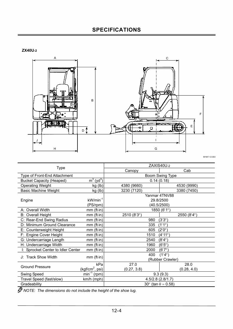
SPECIFICATIONS
12-4
ZX40U-2
M1M7-12-003
ZAXIS40U-2 Type
Canopy Cab Type of Front-End Attachment Boom Swing Type Bucket Capacity (Heaped) m3 (yd3) 0.14 (0.18) Operating Weight kg (lb) 4380 (9660) 4530 (9990) Basic Machine Weight kg (lb) 3230 (7120) 3380 (7450)
Engine kW/min-1
(PS/rpm)
Yanmar 4TNV88 29.8/2500
(40.5/2500) A: Overall Width mm (ft⋅in) 1850 (6′1″) B: Overall Height mm (ft⋅in) 2510 (8′3″) 2550 (8′4″) C: Rear-End Swing Radius mm (ft⋅in) 980 (3′3″) D: Minimum Ground Clearance mm (ft⋅in) 335 (1′1″) E: Counterweight Height mm (ft⋅in) 605 (2′0″) F: Engine Cover Height mm (ft⋅in) 1510 (4′11″) G: Undercarriage Length mm (ft⋅in) 2540 (8′4″) H: Undercarriage Width mm (ft⋅in) 1960 (6′5″) I: Sprocket Center to Idler Center mm (ft⋅in) 2000 (6′7″)
J: Track Shoe Width mm (ft⋅in) 400 (1′4″) (Rubber Crawler)
Ground Pressure kPa (kgf/cm2, psi)
27.0 (0.27, 3.8)
28.0 (0.28, 4.0)
Swing Speed min�1 (rpm) 9.3 (9.3) Travel Speed (fast/slow) km/h (mph) 4.5/2.8 (2.8/1.7) Gradeability 30° (tan θ = 0.58) NOTE: The dimensions do not include the height of the shoe lug.
A
B
D
J
H
C
F
E
I
G

SPECIFICATIONS
12-5
ZX50U-2
M1M7-12-004
ZAXIS50U-2 Type
Canopy Cab Type of Front-End Attachment Boom Swing Type Bucket Capacity (Heaped) m3 (yd3) 0.16 (0.21) Operating Weight kg (lb) 4730 (10430) 4880 (10760) Basic Machine Weight kg (lb) 3560 (7850) 3710 (8180)
Engine kW/min-1
(PS/rpm)
Yanmar 4TNV88 29.8/2500
(40.5/2500) A: Overall Width mm (ft⋅in) 1850 (6′1″) B: Overall Height mm (ft⋅in) 2510 (8′3″) 2550 (8′4″) C: Rear-End Swing Radius mm (ft⋅in) 1000 (3′3″) D: Minimum Ground Clearance mm (ft⋅in) 335 (1′1″) E: Counterweight Height mm (ft⋅in) 605 (2′0″) F: Engine Cover Height mm (ft⋅in) 1510 (4′11″) G: Undercarriage Length mm (ft⋅in) 2540 (8′4″) H: Undercarriage Width mm (ft⋅in) 2000 (6′7″) I: Sprocket Center to Idler Center mm (ft⋅in) 2000 (6′7″)
J: Track Shoe Width mm (ft⋅in) 400 (1′4″) (Rubber Crawler)
Ground Pressure kPa (kgf/cm2, psi)
29.0 (0.30, 4.3)
30.0 (0.30, 4.3)
Swing Speed min�1 (rpm) 9.3 (9.3) Travel Speed (fast/slow) km/h (mph) 4.5/2.8 (2.8/1.7) Gradeability 30° (tan θ = 0.58) NOTE: The dimensions do not include the height of the shoe lug.
A
B
D
J
H
C
F
E
I
G

SPECIFICATIONS
12-6
WORKING RANGES
ZX27U-2
M1M7-12-005
ZAXIS27U-2
Canopy Cab A: Maximum Digging Reach mm (ft⋅in) 4670 (15′4″) [4920 (16′2″)] B: Maximum Digging Depth mm (ft⋅in) 2620 (8′7″) [2920 (9′7″)] C: Maximum Cutting Height mm (ft⋅in) 4460 (14′8″) [4570 (14′12″)] 4290 (14′1″) [4350 (14′3″)] D: Maximum Dumping Height mm (ft⋅in) 3210 (10′6″) [3320 (10′11″)] 3040 (10′0″) [3120 (10′3″)] E: Transport Height (Rubber Crawler) mm (ft⋅in) 2460 (8′1″) 2500 (8′2″)
F: Overall Transport Length mm (ft⋅in) 4200 (13′9″) [4280 (14′1″)] G: Minimum Swing Radius mm (ft⋅in) 1950 (6′5″) [2030 (6′8″)] 2050 (6′9″) [2090 (6′10″)] H: Boom-Swing Pivot Offset Distance mm (ft⋅in) 100 (4″)
I: Blade Bottom Highest Position (above ground level) 360 (1′2″)
J: Blade Bottom Lowest Position (above ground level) mm (ft⋅in) 315 (1′0″)
K: Offset Distance mm (ft⋅in) L605 (L 2′0″) R740 (R 2′5″)
L605 (L 2′0″) R700 (R 2′4″)
Maximum Boom-Swing Angle L72°/R62° L62°/R62° NOTE: The dimensions do not include the height of the shoe lug.
The dimensions for the machine equipped with the long arm are shown in brackets [ ].
E
G
D
C
B
F
A
J
I
K (Left)
H
K (Right)

SPECIFICATIONS
12-7
ZX30U-2
M1M7-12-005
ZAXIS30U-2
Canopy Cab A: Maximum Digging Reach mm (ft⋅in) 4900 (16′1″) [5170 (17′0″)] B: Maximum Digging Depth mm (ft⋅in) 2830 (9′3″) [3130 (10′3″)] C: Maximum Cutting Height mm (ft⋅in) 4680 (15′4″) [4720 (15′6″)] 4450 (14′7″) [4480 (14′8″)] D: Maximum Dumping Height mm (ft⋅in) 3260 (10′8″) [3340 (11′0″)] 3040 (10′0″) [3130 (10′3″)] E: Transport Height (Rubber Crawler) mm (ft⋅in) 2460 (8′1″) 2500 (8′2″)
F: Overall Transport Length mm (ft⋅in) 4450 (14′7″) [4560 (15′0″)] G: Minimum Swing Radius mm (ft⋅in) 1940 (6′4″) [2060 (6′9″)] 2140 (7′0″) [2170 (7′1″)] H: Boom-Swing Pivot Offset Distance mm (ft⋅in) 100 (4″)
I: Blade Bottom Highest Position (above ground level) 360 (1′2″)
J: Blade Bottom Lowest Position (above ground level) mm (ft⋅in) 315 (1′0″)
K: Offset Distance mm (ft⋅in) L605 (L 2′0″) R740 (R 2′5″)
L605 (L 2′0″) R700 (R 2′4″)
Maximum Boom-Swing Angle L72°/R62° L62°/R62° NOTE: The dimensions do not include the height of the shoe lug.
The dimensions for the machine equipped with the long arm are shown in brackets [ ].
E
G
D
C
B
F
A
J
I
K (Left)
H
K (Right)
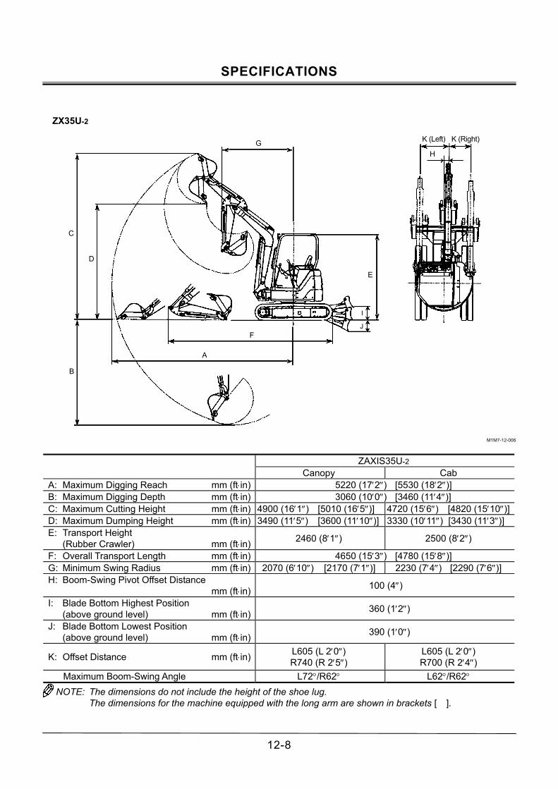
SPECIFICATIONS
12-8
ZX35U-2
M1M7-12-006
ZAXIS35U-2
Canopy Cab A: Maximum Digging Reach mm (ft⋅in) 5220 (17′2″) [5530 (18′2″)] B: Maximum Digging Depth mm (ft⋅in) 3060 (10′0″) [3460 (11′4″)] C: Maximum Cutting Height mm (ft⋅in) 4900 (16′1″) [5010 (16′5″)] 4720 (15′6″) [4820 (15′10″)]D: Maximum Dumping Height mm (ft⋅in) 3490 (11′5″) [3600 (11′10″)] 3330 (10′11″) [3430 (11′3″)] E: Transport Height
(Rubber Crawler) mm (ft⋅in) 2460 (8′1″) 2500 (8′2″)
F: Overall Transport Length mm (ft⋅in) 4650 (15′3″) [4780 (15′8″)] G: Minimum Swing Radius mm (ft⋅in) 2070 (6′10″) [2170 (7′1″)] 2230 (7′4″) [2290 (7′6″)] H: Boom-Swing Pivot Offset Distance
mm (ft⋅in) 100 (4″)
I: Blade Bottom Highest Position (above ground level) mm (ft⋅in) 360 (1′2″)
J: Blade Bottom Lowest Position (above ground level) mm (ft⋅in) 390 (1′0″)
K: Offset Distance mm (ft⋅in) L605 (L 2′0″) R740 (R 2′5″)
L605 (L 2′0″) R700 (R 2′4″)
Maximum Boom-Swing Angle L72°/R62° L62°/R62° NOTE: The dimensions do not include the height of the shoe lug.
The dimensions for the machine equipped with the long arm are shown in brackets [ ].
E
G
D
C
B
F
A
J
I
H
K (Left) K (Right)

SPECIFICATIONS
12-9
ZX40U-2
M1M7-12-007
ZAXIS40U-2
Canopy Cab A: Maximum Digging Reach mm (ft⋅in) 5750 (18′10″) [6050 (19′10″)] B: Maximum Digging Depth mm (ft⋅in) 3350 (11′0″) [3660 (12′0″)] C: Maximum Cutting Height mm (ft⋅in) 5600 (18′4″) [5840 (19′2″)] 5480 (18′0″) [5710 (18′9″)] D: Maximum Dumping Height mm (ft⋅in) 3920 (12′10″) [4160 (13′8″)] 3810 (12′6″) [4040 (13′3″)] E: Transport Height (Rubber Crawler) mm (ft⋅in) 2510 (8′3″) 2550 (8′4″)
F: Overall Transport Length mm (ft⋅in) 5340 (17′6″) [5380 (17′8″)] G: Minimum Swing Radius mm (ft⋅in) 2190 (7′2″) [2340 (7′8″)] 2270 (7′5″) [2390 (7′10″)] H: Boom-Swing Pivot Offset Distance
mm (ft⋅in) 100 (4″)
I: Blade Bottom Highest Position (above ground level) mm (ft⋅in) 425 (1′5″)
J: Blade Bottom Lowest Position (above ground level) mm (ft⋅in) 335 (1′1″)
K: Offset Distance mm (ft⋅in) L690 (L 2′3″) R860 (R 2′10″)
Maximum Boom-Swing Angle L80°/R60° NOTE: The dimensions do not include the height of the shoe lug.
The dimensions for the machine equipped with the long arm are shown in brackets [ ].
E
G
D
C
B
F
A
J
I
K (Left)
H
K (Right)

SPECIFICATIONS
12-10
ZX50U-2
M1M7-12-008
ZAXIS50U-2
Canopy Cab A: Maximum Digging Reach mm (ft⋅in) 6000 (19′8″) [6250 (20′6″)] B: Maximum Digging Depth mm (ft⋅in) 3600 (11′10″) [3860 (12′8″)] C: Maximum Cutting Height mm (ft⋅in) 5770 (18′11″) [6020 (19′9″)] 5640 (18′6″) [5870 (19′3″)] D: Maximum Dumping Height mm (ft⋅in) 4100 (13′5″) [4330 (14′2″)] 4000 (13′1″) [4200 (13′9″)] E: Transport Height
(Rubber Crawler) mm (ft⋅in) 2510 (8′3″) 2550 (8′4″)
F: Overall Transport Length mm (ft⋅in) 5460 (17′11″) [5520 (18′1″)] G: Minimum Swing Radius mm (ft⋅in) 2150 (7′1″) [2260 (7′5″)] 2300 (7′7″) [2340 (7′8″)] H: Boom-Swing Pivot Offset Distance
mm (ft⋅in) 100 (4″)
I: Blade Bottom Highest Position (above ground level) mm (ft⋅in) 425 (1′5″)
J: Blade Bottom Lowest Position (above ground level) mm (ft⋅in) 335 (1′1″)
K: Offset Distance mm (ft⋅in) L690 (L 2′3″) R860 (R 2′10″)
Maximum Boom-Swing Angle L80°/R60° NOTE: The dimensions do not include the height of the shoe lug.
The dimensions for the machine equipped with the long arm are shown in brackets [ ].
A
E
G
D
C
B
F
A
J
I
K (Left)
H
K (Right)

SPECIFICATIONS
12-11
SHOE TYPES AND APPLICATIONS
ZAXIS27U-2 (Canopy)
Shoe Width 300 mm (1′0″) Rubber Shoe
300 mm (1′0″) Grouser Shoe
Application For Paved Road (Standard)
For Ordinary Ground (Option)
Operating Weight kg (lb) 2800 (6170) 2810 (6190) Minimum Ground Clearance mm (ft⋅in) 320 (1′1″) 310 (1′0″)
Undercarriage Length mm (ft⋅in) 1950 (6′5″) 1920 (6′4″)
Undercarriage Width mm (ft⋅in) 1550 (5′1″) 1550 (5′1″)
Ground Pressure kPa (kgf/cm2, psi)
27.0 (0.28, 4.0)
28.0 (0.29, 4.1)
ZAXIS27U-2 (Cab)
Shoe Width 300 mm (1′0″) Rubber Shoe
300 mm (1′0″) Grouser Shoe
Application For Paved Road (Standard)
For Ordinary Ground (Option)
Operating Weight kg (lb) 2950 (6500) 3040 (6700) Minimum Ground Clearance mm (ft⋅in) 320 (1′1″) 310 (1′0″)
Undercarriage Length mm (ft⋅in) 1950 (6′5″) 1920 (6′4″)
Undercarriage Width mm (ft⋅in) 1550 (5′1″) 1550 (5′1″)
Ground Pressure kPa (kgf/cm2, psi)
28.0 (0.29, 4.1)
29.0 (0.30, 4.3)
NOTE: The specifications for the front-end attachment
are for 1.17 m (3 ft 10 in) arm with ISO 0.08 m3 (0.10 yd3) bucket.

SPECIFICATIONS
12-12
ZAXIS30U-2 (Canopy)
Shoe Width 300 mm (1′0″) Rubber Shoe
300 mm (1′0″) Grouser Shoe
Application For Paved Road (Standard)
For Ordinary Ground (Option)
Operating Weight kg (lb) 3070 (6770) 3155 (6960) Minimum Ground Clearance mm (ft⋅in) 290 (11″) 280 (11″)
Undercarriage Length mm (ft⋅in) 2100 (6′11″) 2120 (6′11″)
Undercarriage Width mm (ft⋅in) 1550 (5′1″) 1550 (5′1″)
Ground Pressure kPa (kgf/cm2, psi)
28.0 (0.28, 4.0)
28.0 (0.29, 4.1)
ZAXIS30U-2 (Cab)
Shoe Width 300 mm (1′0″) Rubber Shoe
300 mm (1′0″) Grouser Shoe
Application For Paved Road (Standard)
For Ordinary Ground (Option)
Operating Weight kg (lb) 3220 (7100) 3305 (7290) Minimum Ground Clearance mm (ft⋅in) 290 (11″) 280 (11″)
Undercarriage Length mm (ft⋅in) 2100 (6′11″) 2120 (6′11″)
Undercarriage Width mm (ft⋅in) 1550 (5′1″) 1550 (5′1″)
Ground Pressure kPa (kgf/cm2, psi)
29.0 (0.30, 4.3)
30.0 (0.30, 4.3)
NOTE: The specifications for the front-end attachment
are for 1.17 m (3 ft 10 in) arm with ISO 0.09 m3 (0.12 yd3) bucket.

SPECIFICATIONS
12-13
ZAXIS35U-2 (Canopy)
Shoe Width 300 mm (1′0″) Rubber Shoe
300 mm (1′0″) Grouser Shoe
Application For Paved Road (Standard)
For Ordinary Ground (Option)
Operating Weight kg (lb) 3480 (7670) 3565 (7860) Minimum Ground Clearance mm (ft⋅in) 290 (11″) 280 (11″)
Undercarriage Length mm (ft⋅in) 2100 (6′11″) 2120 (6′11″)
Undercarriage Width mm (ft⋅in) 1740 (5′9″) 1740 (5′9″)
Ground Pressure kPa (kgf/cm2, psi)
31.0 (0.32, 4.6)
32.0 (0.33, 4.7)
ZAXIS35U-2 (Cab)
Shoe Width 300 mm (1′0″) Rubber Shoe
300 mm (1′0″) Grouser Shoe
Application For Paved Road (Standard)
For Ordinary Ground (Option)
Operating Weight kg (lb) 3630 (8000) 3715 (8190) Minimum Ground Clearance mm (ft⋅in) 290 (11″) 280 (11″)
Undercarriage Length mm (ft⋅in) 2100 (6′11″) 2120 (6′11″)
Undercarriage Width mm (ft⋅in) 1740 (5′9″) 1740 (5′9″)
Ground Pressure kPa (kgf/cm2, psi)
33.0 (0.33, 4.7)
33.0 (0.34, 4.8)
NOTE: The specifications for the front-end attachment
are for 1.32 m (4 ft 4 in) arm with ISO 0.11 m3 (0.14 yd3) bucket.

SPECIFICATIONS
12-14
ZAXIS40U-2 (Canopy)
Shoe Width 400 mm (1′4″) Rubber Shoe
400 mm (1′4″) Grouser Shoe
Application For Paved Road (Standard)
For Ordinary Ground (Option)
Operating Weight kg (lb) 4380 (9660) 4450 (9810) Minimum Ground Clearance mm (ft⋅in) 335 (1′1″) 315 (1′0″)
Undercarriage Length mm (ft⋅in) 2540 (8′4″) 2490 (8′2″)
Undercarriage Width mm (ft⋅in) 1960 (6′5″) 1960 (6′5″)
Ground Pressure kPa (kgf/cm2, psi)
27.0 (0.27, 3.8)
28.0 (0.28, 4.0)
ZAXIS40U-2 (Cab)
Shoe Width 400 mm (1′4″) Rubber Shoe
400 mm (1′4″) Grouser Shoe
Application For Paved Road (Standard)
For Ordinary Ground (Option)
Operating Weight kg (lb) 4530 (9990) 4600 (10140) Minimum Ground Clearance mm (ft⋅in) 335 (1′1″) 315 (1′0″)
Undercarriage Length mm (ft⋅in) 2540 (8′4″) 2490 (8′2″)
Undercarriage Width mm (ft⋅in) 1960 (6′5″) 1960 (6′5″)
Ground Pressure kPa (kgf/cm2, psi)
28.0 (0.28, 4.0)
29.0 (0.29, 4.1)
NOTE: The specifications for the front-end attachment
are for 1.38 m (4 ft 6 in) arm with ISO 0.14 m3 (0.18 yd3) bucket.

SPECIFICATIONS
12-15
ZAXIS50U-2 (Canopy)
Shoe Width 400 mm (1′4″) Rubber Shoe
400 mm (1′4″) Grouser Shoe
Application For Paved Road (Standard)
For Ordinary Ground (Option)
Operating Weight kg (lb) 4730 (10430) 4800 (10580) Minimum Ground Clearance mm (ft⋅in) 335 (1′1″) 315 (1′0″)
Undercarriage Length mm (ft⋅in) 2540 (8′4″) 2490 (8′2″)
Undercarriage Width mm (ft⋅in) 2000 (6′7″) 2000 (6′7″)
Ground Pressure kPa (kgf/cm2, psi)
29.0 (0.30, 4.3)
30.0 (0.30, 4.3)
ZAXIS50U-2 (Cab)
Shoe Width 400 mm (1′4″) Rubber Shoe
400 mm (1′4″) Grouser Shoe
Application For Paved Road (Standard)
For Ordinary Ground (Option)
Operating Weight kg (lb) 4880 (10760) 4950 (10910) Minimum Ground Clearance mm (ft⋅in) 335 (1′1″) 315 (1′0″)
Undercarriage Length mm (ft⋅in) 2540 (8′4″) 2490 (8′2″)
Undercarriage Width mm (ft⋅in) 2000 (6′7″) 2000 (6′7″)
Ground Pressure kPa (kgf/cm2, psi)
30.0 (0.30, 4.3)
31.0 (0.31, 4.4)
NOTE: The specifications for the front-end attachment
are for 1.38 m (4 ft 6 in) arm with ISO 0.16 m3 (0.21 yd3) bucket.

SPECIFICATIONS
12-16
BUCKET TYPES AND APPLICATIONS
ZAXIS27U-2
Bucket Width mm Front-End Attachment
Bucket Bucket Capacity
m3 (yd3) ISO (Heaped)
(With side cutter) mm (in)
(Without side cutter) mm (in)
1.17 m (3′10″)
Arm
1.47 m (5′0″) Arm
Hoe Bucket 0.05 (0.065) 0.06 (0.078) 0.07 (0.092) 0.08 (0.105) 0.09 (0.118) 0.10 (0.121)
350 (14″) 400 (16″) 450 (18″) 500 (20″) 550 (22″) 600 (24″)
300 (12″) 350 (14″) 400 (16″) 450 (18″) 500 (20″) 550 (22″)
! ! ! ! " "
! ! ! " " #
NOTE: (1) Symbols in the above table have the
following meanings. !: General excavating ": Light duty excavating #: Loading work (2) Hoe bucket is applicable to the following
types of work. General excavating: For digging and loading operation of sand,
gravel, clay, ordinary earth and so on. Light duty excavating:
For digging loading operation of dried, loosened earth, sand, mud so on.
Their bulk density shall be less than 1600 kg/m3 as a standard.
For loading operation of dried, loosened earth and sand.
Their bulk density shall be less than 1100 kg/m3 as a standard.

SPECIFICATIONS
12-17
ZAXIS30U-2
Bucket Width mm Front-End Attachment
Bucket Bucket Capacity
m3 (yd3) ISO (Heaped)
(With side cutter) mm (in)
(Without side cutter) mm (in)
1.17 m (3′10″)
Arm
1.52 m (5′0″) Arm
Hoe Bucket 0.040 (0.052) 0.055 (0.072) 0.065 (0.085) 0.08 (0.10) 0.09 (0.12) 0.10 (0.13) 0.11 (0.14) 0.13 (0.17)
300 (12″) 350 (14″) 400 (16″) 450 (18″) 500 (20″) 550 (22″) 600 (24″) 650 (26″)
250 (10″) 300 (12″) 350 (14″) 400 (16″) 450 (18″) 500 (20″) 550 (22″) 600 (24″)
! ! ! ! ! " # #
! ! ! ! " # # −
NOTE: (1) Symbols in the above table have the
following meanings. !: General excavating ": Light duty excavating #: Loading work (2) Hoe bucket is applicable to the following
types of work. General excavating: For digging and loading operation of sand,
gravel, clay, ordinary earth and so on. Light duty excavating:
For digging loading operation of dried, loosened earth, sand, mud so on.
Their bulk density shall be less than 1600 kg/m3 as a standard.
For loading operation of dried, loosened earth and sand.
Their bulk density shall be less than 1100 kg/m3 as a standard.

SPECIFICATIONS
12-18
ZAXIS35U-2
Bucket Width mm Front-End Attachment
Bucket Bucket Capacity
m3 (yd3) ISO (Heaped)
(With side cutter) mm (in)
(Without side cutter) mm (in)
1.32 m (4′4″) Arm
1.72 m (5′8″) Arm
Hoe Bucket 0.040 (0.052) 0.055 (0.072) 0.065 (0.085) 0.08 (0.10) 0.09 (0.12) 0.10 (0.13) 0.11 (0.14) 0.13 (0.17) 0.14 (0.18) 0.15 (0.20)
300 (12″) 350 (14″) 400 (16″) 450 (18″) 500 (20″) 550 (22″) 600 (24″) 650 (26″) 700 (28″) 750 (30″)
250 (10″) 300 (12″) 350 (14″) 400 (16″) 450 (18″) 500 (20″) 550 (22″) 600 (24″) 650 (26″) 700 (28″)
! ! ! ! ! ! ! " # #
! ! ! ! ! ! " # − −
NOTE: (1) Symbols in the above table have the
following meanings. !: General excavating ": Light duty excavating #: Loading work (2) Hoe bucket is applicable to the following
types of work. General excavating: For digging and loading operation of sand,
gravel, clay, ordinary earth and so on. Light duty excavating:
For digging loading operation of dried, loosened earth, sand, mud so on.
Their bulk density shall be less than 1600 kg/m3 as a standard.
For loading operation of dried, loosened earth and sand.
Their bulk density shall be less than 1100 kg/m3 as a standard.

SPECIFICATIONS
12-19
ZAXIS40U-2, ZAXIS50U-2
Bucket Width mm Front-End Attachment ZAXIS40U-2 ZAXIS50U-2
Bucket Bucket Capacity
m3 (yd3) ISO (Heaped)
(With side cutter)
mm (in)
(Without side cutter)
mm (in)
1.38 m (4′6″) Arm
1.69 m (5′7″) Arm
1.38 m (4′6″) Arm
1.69 m (5′7″) Arm
Hoe Bucket 0.10 (0.13) 0.11 (0.14) 0.13 (0.17) 0.14 (0.18) 0.16 (0.21) 0.17 (0.22)
450 (18″) 500 (20″) 550 (22″) 600 (24″) 650 (26″) 700 (28″)
400 (16″) 450 (18″) 500 (20″) 550 (22″) 600 (24″) 650 (26″)
! ! ! ! # #
! ! " # # #
! ! ! ! ! #
! ! ! ! " #
NOTE: (1) Symbols in the above table have the
following meanings. !: General excavating ": Light duty excavating #: Loading work (2) Hoe bucket is applicable to the following
types of work. General excavating: For digging and loading operation of sand,
gravel, clay, ordinary earth and so on. Light duty excavating:
For digging loading operation of dried, loosened earth, sand, mud so on.
Their bulk density shall be less than 1600 kg/m3 as a standard.
For loading operation of dried, loosened earth and sand.
Their bulk density shall be less than 1100 kg/m3 as a standard.

SPECIFICATIONS
12-20
MEMO
.....................................................................................................................................................................................
.....................................................................................................................................................................................
.....................................................................................................................................................................................
.....................................................................................................................................................................................
.....................................................................................................................................................................................
.....................................................................................................................................................................................
.....................................................................................................................................................................................
.....................................................................................................................................................................................
.....................................................................................................................................................................................
.....................................................................................................................................................................................
.....................................................................................................................................................................................
.....................................................................................................................................................................................
.....................................................................................................................................................................................
.....................................................................................................................................................................................
.....................................................................................................................................................................................
.....................................................................................................................................................................................
.....................................................................................................................................................................................
.....................................................................................................................................................................................
.....................................................................................................................................................................................
.....................................................................................................................................................................................
.....................................................................................................................................................................................
.....................................................................................................................................................................................
.....................................................................................................................................................................................
.....................................................................................................................................................................................
.....................................................................................................................................................................................
.....................................................................................................................................................................................
.....................................................................................................................................................................................
.....................................................................................................................................................................................
.....................................................................................................................................................................................
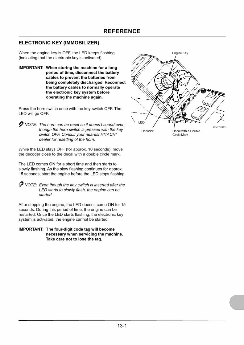
REFERENCE
13-1
ELECTRONIC KEY (IMMOBILIZER)
When the engine key is OFF, the LED keeps flashing (indicating that the electronic key is activated) IMPORTANT: When storing the machine for a long
period of time, disconnect the battery cables to prevent the batteries from being completely discharged. Reconnect the battery cables to normally operate the electronic key system before operating the machine again.
Press the horn switch once with the key switch OFF. The LED will go OFF.
NOTE: The horn can be reset so it doesn�t sound even though the horn switch is pressed with the key switch OFF. Consult your nearest HITACHI dealer for resetting of the horn.
While the LED stays OFF (for approx. 10 seconds), move the decoder close to the decal with a double circle mark. The LED comes ON for a short time and then starts to slowly flashing. As the slow flashing continues for approx. 15 seconds, start the engine before the LED stops flashing.
NOTE: Even though the key switch is inserted after the LED starts to slowly flash, the engine can be started.
After stopping the engine, the LED doesn�t come ON for 15 seconds. During this period of time, the engine can be restarted. Once the LED starts flashing, the electronic key system is activated, the engine cannot be started. IMPORTANT: The four-digit code tag will become
necessary when servicing the machine. Take care not to lose the tag.
M1M7-13-001
Engine Key
LED
Decoder Decal with a Double Circle Mark

REFERENCE
13-2
EMERGENT OVERRIDING PROCEDURE OF ELECTRONIC KEY
1. Press the horn switch with the key switch OFF. After the LED goes OFF, wait until the LED starts flashing. After the LED start flashing, press the horn switch. Repeat this operation pattern four times in total.
2. The LED will start flashing at very short intervals. After approx. two minutes pass, the LED will change to slow flashing. (Overriding preparation mode)
3. Immediately turn the key switch ON/OFF twice. The LED flashing will become very slow.
4. As soon as the LED completes to flash by the times equal to the first figure of the four-digit code on the tag, press the horn switch. Then, repeat this procedure by the times equal to the first figure of the four-digit code.
5. Turn the key switch ON. The LED will go OFF. Then, the electric immobilize key is deactivated, allowing the engine to be manually started.
NOTE: Turn the key switch OFF to restore the electric immobilize key function.
IMPORTANT: The four-digit code tag will become
necessary when servicing the machine. Take care not to lose the tag.
M1M7-13-001
Engine Key
LED
Decoder Decal with a Double Circle Mark

REFERENCE
13-3
ADDITIONAL COUNTERWEIGHT
The mass values of the additional counterweights are shown in the table below.
Model Mass Overhang from the end of the base machine
ZX27U-2 190 kg 90 mm ZX30U-2 190 kg 90 mm ZX35U-2 230 kg 90 mm ZX40U-2 220 kg 80 mm ZX50U-2 220 kg 80 mm
Removal
Remove the additional counterweights by following the procedure below. 1. Suspend additional counterweight (1) using the lifting
tools described below so that the counterweight doesn�t fall. Wire rope (2) × 2 : Breaking load: more than 7 kN Pin Shackle (3) × 2 : JIS Nominal size: 8 or more Eye bolt (4) × 2 : M20
2. Remove mounting bolts (5).
CAUTION: Take care if the additional counterweight is eccentrically lifted, the lifted counterweight may widely sway. Place the removed additional counterweight on a level surface.
Installation
1. Lift the additional counterweight using the lifting tools described above. Mount the additional counterweight on the standard counterweight. Tighten mounting bolts (5). (Tightening torque: 540 N⋅m)
ZX27U-2, ZX30U-2, ZX35U-2 Wrench Size : 24 mm Tightening Torque : 265 N⋅m (27 kgf⋅m)
ZX40U-2, ZX50U-2 Wrench Size : 30 mm Tightening Torque : 540 N⋅m (55.1 kgf⋅m)
M1M7-13-002
2
3
4
1
56

REFERENCE
13-4
MEMO
.....................................................................................................................................................................................
.....................................................................................................................................................................................
.....................................................................................................................................................................................
.....................................................................................................................................................................................
.....................................................................................................................................................................................
.....................................................................................................................................................................................
.....................................................................................................................................................................................
.....................................................................................................................................................................................
.....................................................................................................................................................................................
.....................................................................................................................................................................................
.....................................................................................................................................................................................
.....................................................................................................................................................................................
.....................................................................................................................................................................................
.....................................................................................................................................................................................
.....................................................................................................................................................................................
.....................................................................................................................................................................................
.....................................................................................................................................................................................
.....................................................................................................................................................................................
.....................................................................................................................................................................................
.....................................................................................................................................................................................
.....................................................................................................................................................................................
.....................................................................................................................................................................................
.....................................................................................................................................................................................
.....................................................................................................................................................................................
.....................................................................................................................................................................................
.....................................................................................................................................................................................
.....................................................................................................................................................................................
.....................................................................................................................................................................................
.....................................................................................................................................................................................

INDEX
14-1
A AM/FM Radio Operation ....................................1-16 Additional Counterweight...................................13-3 Adjust the Operator�s Seat.................................. S-5 Adjusting Operator�s Seat..................................1-20 Adjusting Track Sag (Rubber Crawler) and Check for Damage................................7-53 Air Cleaner .........................................................7-40 Air Conditioner Operation ..................................1-12 Alternator Indicator ..............................................1-7 Auto-Idle Mode Switch.......................................1-11 Auto-Idle Control................................................5-10 Auxiliary Flow Rate Control (Optional) ..............5-25 Auxiliary Pedal (Optional) ....................................5-5 Avoid Abusive Operation ...................................5-13 Avoid Applying Heat to Lines Containing Flammable Fluids..................... S-27 Avoid Colliding Blade Against Rocks.................5-17 Avoid Colliding Boom Cylinder with Track.........5-17 Avoid Driving Bucket Teeth Into Ground ...........5-13 Avoid Excavation Using Upperstructure and/or Boom Swing Power ..........................5-14 Avoid Heating Near Pressurized Fluid Lines.... S-27 Avoid High-Pressure Fluids .............................. S-23 Avoid Hitting Blade with Bucket.........................5-17 Avoid Injury from Back-Over and Swing Accidents .................................. S-12 Avoid Injury from Rollaway Accidents .............. S-11 Avoid Other than Specified Machine Operations ...................................................5-15 Avoid Power Lines ............................................ S-15 Avoid Striking with Bucket .................................5-14 Avoid Tipping .................................................... S-14 Avoid Undercutting ........................................... S-13 B Break-In ...............................................................2-1 Batteries.............................................................7-46 Before Starting Engine.........................................3-1 Beware of Exhaust Fumes................................ S-26 Blade Lever..........................................................5-6 Blade Pins..........................................................7-14 Boom Cylinder May Hit Blade............................5-16 Boom-Swing Pedal ............................................5-4 Breaking in New Machine....................................2-1 Bucket Types and Applications .......................12-16 Bucket and Link Pins .........................................7-14 C Components Name..............................................1-1 Consumable Parts List.........................................8-1 Cab Door Release lever (Only on cab-equipped machines) ..............1-18 Cab Light (Cab-equipped machines).................1-23 Change Coolant.................................................7-44 Change Engine Oil.............................................7-17 Change Hydraulic Oil.........................................7-24
Check Air conditioner (Machine with Cab) ..................................... 7-61 Check Bucket Hook (Optional).......................... 7-60 Check Bucket Teeth for Looseness and/or Wear ................................................ 7-50 Check Coolant Level ......................................... 7-42 Check Fuel Hoses............................................. 7-39 Check Hoses and Lines .................................... 7-31 Check Hydraulic Oil Level ................................. 7-22 Check Injection Nozzle...................................... 7-65 Check Injection Timing...................................... 7-65 Check Machine After Starting Engine ................. 3-4 Check Radiator Cap.......................................... 7-66 Check Starter and Alternator............................. 7-66 Check Tightening Torque of Bolts and Nuts............................................. 7-67 Check Track Sag (Steel Crawler) ..................... 7-57 Check Water Separator..................................... 7-37 Check and Adjust Fan Belt Tension.................. 7-43 Check and Adjust Valve Clearance .................. 7-65 Check and Replace Seat Belt ........................... 7-60 Clean Cab Floor ................................................ 7-64 Clean Radiator .................................................. 7-45 Clean Re-circulation Filter................................. 7-62 Clean Suction Filter ........................................... 7-27 Clean and Replace Air Conditioner Re-circulation Filter ..................................... 7-62 Clean the Air Cleaner Element.......................... 7-40 Confirm Direction of Machine to be Driven .........S-9 Control Lever (ISO Excavator Pattern) ............... 5-1 Control Lever (SAE-Backhoe Pattern) --- If Equipped (2 Way Multi Valve) ............... 5-3 Control Lever Universal Joint ............................ 7-16 Coolant Temperature Gauge .............................. 1-5 Cooling System ................................................. 7-41 Crusher Operation (Optional)............................ 5-23 D Driving The Machine ........................................... 4-1 Daily Inspection ................................................... 7-5 Dig with Caution ................................................S-15 Dispose of Waste Properly................................S-30 Do Not Use for Craning Operations ..................S-16 Drain Fuel Tank Sump ...................................... 7-37 Drain Hydraulic Oil Tank Sump......................... 7-23 Drive Machine Safely ........................................S-10 Driving In Water or on Soft Ground..................... 4-7 E Electrical System............................................... 7-46 Electronic Key (Immobilizer) ............................. 13-1 Emergency Exit (Cab-equipped machines) ...... 1-22 Emergent Overriding Procedure of Electronic Key ............................................. 13-2 Engine ............................................................. 7-17 Engine Oil Level ................................................ 7-17

INDEX
14-2
Engine Oil Pressure Indicator..............................1-6 Evacuating in Case of Fire................................ S-26 F Fast Travel Mode Indicator ..................................1-7 Fasten Your Seat Belt......................................... S-5 Follow Safety Instructions................................... S-2 Front Joint Pins..................................................7-11 Fuel Gauge ..........................................................1-5 Fuel Level Indicator .............................................1-6 Fuel System.......................................................7-36 G Grading Operation .............................................5-13 Greasing ............................................................7-11 H Handle Chemical Products Safely .................... S-29 Handle Fluids Safely � Avoid Fires................... S-17 How to Operate Trip Meter ..................................1-9 Hydraulic Breaker (Optional) .............................5-20 Hydraulic System...............................................7-21 I Inspect Machine Daily......................................... S-3 Inspection and Maintenance of Hydraulic Equipment ....................................7-21 Investigate Job Site Beforehand......................... S-8 J Jump Starting...................................................... S-7 K Keep Person Clear from Working Area ............ S-13 Keep Riders Off Machine.................................... S-7 Key Switch ...........................................................1-4 L Lifting Machine with Crane ..................................6-5 Liquid Crystal display (LCD), Display Selection Switch, and Set Switch .....1-8 Loading ................................................................6-2 M Maintenance ........................................................7-1 Maintenance Under Special Environmental Conditions..............................9-1 Maintenance Guide..............................................7-7 Measure Engine Compression Pressure...........7-65 Miscellaneous ....................................................7-50 Monitor Panel.......................................................1-5 Move and Operate Machine Safely .................... S-6 N Never Position Bucket Over Anyone ................ S-13 Never Undercut a High Bank............................ S-14
O Operating Engine ................................................ 3-1 Operation............................................................. 5-1 Operator�S Station............................................... 1-2 Opening/Closing Cab Front Window (Only on cab-equipped machines) ............ 1-19 Opening/Closing Cab Rear Window (Cab-equipped machines)........................... 1-21 Opening/Closing Engine Access Covers ............ 7-3 Opening/Closing Tank Covers ............................ 7-4 Operate Machine Safely.................................... 5-11 Operate Only from Operator�s Seat ....................S-7 Operate with Caution ........................................S-15 Operating Backhoe ........................................... 5-12 Overheat Indicator............................................... 1-6 P Park Machine Safely .........................................S-17 Parking and Stopping on Slope........................... 4-9 Parking on Slopes ............................................... 4-9 Pedals, Levers and Monitor Panel ...................... 1-2 Periodic Replacement of Parts............................ 7-6 Pilot Control Shut-Off Lever ................................ 5-8 Practice Safe Maintenance ...............................S-19 Precautions for After Operating the Machine.... 5-24 Precautions for Blade Operation......................... 5-7 Precautions for Front Attachment and Blade Removal ............................................ 7-14 Precautions for Handling Refrigerant................S-29 Precautions for Installing Wide Bucket or Special Type Bucket ............................... 5-17 Precautions for Operations ............................... 5-11 Precautions for Traveling .................................... 4-4 Precautions for Traveling on Slopes ................... 4-8 Precautions for Using Bucket Hook .................. 5-16 Precautions for Welding and Grinding ..............S-27 Preheat Indicator ................................................. 1-7 Preparation for Inspection and Maintenance .... 7-71 Prepare Machine for Inspection/Maintenance .... 7-2 Prepare for Emergencies ....................................S-2 Prevent Battery Explosions ...............................S-28 Prevent Burns....................................................S-22 Prevent Fires .....................................................S-24 Prevent Parts from Flying..................................S-21 Procedures........................................................... 7-1 Protect Against Flying Debris............................S-16 Protect Against Falling Stones and Debris .........S-9 Protect Against Noise..........................................S-3 Provide Signals for Jobs Involving Multiple Numbers of Machines......................S-9 R Reference.......................................................... 13-1 Radio (Cab Equipped Machines) ...................... 1-15 Raise One Track Using Boom and Arm.............. 4-5 Recognize Safety Information .............................S-1

INDEX
14-3
Remove Paint before Welding or Heating ........ S-28 Removing the Machine From Storage...............10-2 Replace Bucket..................................................7-52 Replace Engine Oil Filter ...................................7-17 Replace Fuel Filter.............................................7-38 Replace Full Flow Filter .....................................7-28 Replace Pilot Filter.............................................7-29 Replace Re-circulation Filter .............................7-62 Replace Rubber Hoses Periodically ................. S-23 Replace Rubber Track.......................................75-6 Replace the Air Cleaner Element ......................7-40 Replacing Fuses ................................................7-49 S Safety .............................................................. S-1 Safety Signs .................................................... S-31 Storage ..............................................................10-1 Safety Transporting .......................................... S-18 Seat Belt (Optional) ...........................................1-23 Securing the Machine to the Trailer for Transportation ..........................................6-3 Shoe Types and Applications ..........................12-11 Specifications.....................................................12-1 Starting Engine ....................................................3-2 Starting in Cold Weather......................................3-3 Stay Clear of Moving Parts ............................... S-21 Stopping the Engine ............................................3-6 Store Attachments Safely ................................. S-22 Storing the Machine...........................................10-1 Support Machine Properly ................................ S-21 Swing Bearing....................................................7-15 Swing Internal Gear ...........................................7-16 Switch Panel ........................................................1-4 System Failure Indicator ......................................1-6 T Transporting.........................................................6-1 Troubleshooting .................................................11-1 The Brand Names of Recommended Oils and Lubricants......................................7-10 Tidy Up Inside Cab ............................................. S-4 Tilt Mechanism Operation..................................7-71 Tilting Floor Down..............................................7-73 Tips for Air Conditioner Usage ..........................1-14 Tool and Operator�s manual Boxes ...................1-20 Towing Machine...................................................4-6 Trailer Loading/Unloading ...................................6-1 Transmission .....................................................7-19 Transporting by Road ..........................................6-1 Travel Levers and Pedals ....................................4-1 Travel Mode Switch .............................................4-3 Travel Reduction Gear.......................................7-19 Traveling on Soft Ground.....................................4-5 U Understand Signal Words................................... S-1
Unloading ............................................................ 6-4 Use Correct Track Shoe.................................... 5-14 Use Handholds and Steps ..................................S-4 Using Booster Batteries ...................................... 3-5 Using Rubber Crawler....................................... 5-18 W Warming Up Operation ....................................... 5-9 Warming Up in Cold Weather ............................. 5-9 Warn Others of Service Work ...........................S-20 Wear Protective Clothing ....................................S-3 Working Ranges................................................ 12-6

INDEX
14-4
MEMO.....................................................................................................................................................................................
.....................................................................................................................................................................................
.....................................................................................................................................................................................
.....................................................................................................................................................................................
.....................................................................................................................................................................................
.....................................................................................................................................................................................
.....................................................................................................................................................................................
.....................................................................................................................................................................................
.....................................................................................................................................................................................
.....................................................................................................................................................................................
.....................................................................................................................................................................................
.....................................................................................................................................................................................
.....................................................................................................................................................................................
.....................................................................................................................................................................................
.....................................................................................................................................................................................
.....................................................................................................................................................................................
.....................................................................................................................................................................................
.....................................................................................................................................................................................
.....................................................................................................................................................................................
.....................................................................................................................................................................................
.....................................................................................................................................................................................
.....................................................................................................................................................................................
.....................................................................................................................................................................................
.....................................................................................................................................................................................
.....................................................................................................................................................................................
.....................................................................................................................................................................................
.....................................................................................................................................................................................
.....................................................................................................................................................................................
.....................................................................................................................................................................................
.....................................................................................................................................................................................