Embed Size (px)
Citation preview
Applied mechanics
11
© A. Protosenia, M. Karasev, V. Ochkurov, 2017
1. Introduction
Construction of underground structures is carried out in various mining and geological conditions and is always associated with deformation of the rock body. Development of geomechanical processes in the vicinity of the under-ground structure contour determines expected subsidence of the earth’s surface, stability of the tunnel vault, the load on its dressing and depends on the mechanical behavior of the rock. At present, prediction of geomechanical processes is performed mainly with application of numerical analysis methods within the framework of the mechanics of contin-uous or discrete media or within the framework of mixed formulation. In construction of underground structures in rocks prone to brittle fracture, the methods of continuum mechanics do not always enable assessment of development of geomechanical processes. Deformation and fracture of rocks are accompanied by formation of new and propagation of existing micro- and macrocracks. At the same time, the rock fracture process does not occur directly when the limit of rock strength is reached but continues until the cemen-tation bonds formed between the rock particles are broken. The deformation process of such media is very complex, it often results in formation of anisotropy of rock deformation properties and requires development of new methods for prediction of geomechanical processes.
Therefore, studies aimed at development of mathematical models that make it possible to consider complex processes of deformation and fracture of rocks, both at the level of speci-
mens and in the vicinity of outcrops, based on the consider-ation of formation and propagation of separating and shear-ing fractures in an explicit form are of current importance.
2. Literature review and problem statement
Mathematical description of deformation and fracture of rocks is made on the basis of various approaches which can be realized within the framework of the mechanics of contin-uous, discrete or discrete-continuous media.
Approaches based on consideration of mechanical rock behavior at micro- and macrolevels (microstructural and mac-rostructural approaches) have found a widespread use in ide-alization of rock deformation and fracture in the framework of continuum mechanics [1, 2], These works combine the princi-ple of considering deformation processes at microstructural sites by simulating interaction between the surfaces of rock weakening at a microlevel. Such approach makes it possible to refuse from consideration of the predetermined direction of crack propagation but obtain information on formation of new cracks and their effect on the mechanical behavior of an elementary volume of rock directly in the calculation process. The disadvantage of the proposed approach is inability to take into account influence of cracks formed at the microlevel on the behavior of adjacent elements.
The models of rock deformation based on the macro-structural approach [3, 4] enable solution of a wide range of problems and can be effectively implemented on the basis
INTRODUCTION OF THE METHOD OF
FINITE-DISCRETE ELEMENTS INTO THE
ABAQUS/EXPLICIT SOFTWARE COMPLEX
FOR MODELING DEFORMATION AND
FRACTURE OF ROCKSA . P r o t o s e n i a
DoctorofTechnicalSciences,Professor*M . K a r a s e v
PhD,AssociateProfessor*V . O c h k u r o v
PhD,AssociateProfessor**Departmentofundergroundstructuresand
minesconstructionSaint-PetersburgMiningUniversity
21lineofV.O.,2,Saint-Petersburg,Russia,199106
Розглянуто питання створення моделі дис-кретно-суцільного середовища для опису проце-сів деформування і руйнування гірської породи. Запропоновано методику впровадження методу кінцево-дискретних елементів в рамках програм-ного комплексу для виконання розрахунків на міц-ність Abaqus. Розглянуто приклади чисельного моделювання навантаження зразка гірської поро-ди і прогнозу розвитку геомеханічних процесів в околиці породного оголення
Ключові слова: підземне будівництво, порода, механіка руйнування, метод кінцево-дискретних елементів
Рассмотрены вопросы создания модели дис-кретно-сплошной среды для описания процессов деформирования и разрушения горной породы. Предложена методика внедрения метода конеч-но-дискретных элементов в рамках программно-го комплекса для выполнения прочностных рас-четов Abaqus. Рассмотрены примеры численного моделирования нагружения образца горной поро-ды и прогноза развития геомеханических процес-сов в окрестности породного обнажения
Ключевые слова: подземное строительство, порода, механика разрушения, метод конечно- дискретных элементов
UDC 624.1DOI: 10.15587/1729-4061.2017.116692
Eastern-European Journal of Enterprise Technologies ISSN 1729-3774 6/7 ( 90 ) 2017
12
of numerical analysis methods. However, the disadvantage of macrostructural models of deformation and fracture of rocks is that they are based on a phenomenological approach that does not make it possible to describe some mechanical processes with a sufficient degree of certainty. Parameters of such models are not always physically meaningful and can often be determined only by the trial and error method. In general, it can be noted that such a class of models can well describe deformation processes within the elementary vol-ume. However, since the study of the microcrack formation and propagation is not considered within the framework of these models, this may lead to an incorrect prediction of brittle fracture zones in the outcrop vicinity.
The medium models developed under the method of finite-discrete elements are formulated within the frame-work of the continuum mechanics with elements of the mechanics of discrete media. In the framework of the continuum mechanics, description of mechanical processes at the extreme stage of deformation is made with applica-tion of elements of the theory of elasticity and plasticity. Within the framework of the mechanics of discrete media, possibility of formation of separation and shear cracks or their combination is considered. The first studies in this field [5] are devoted to presentation of basics of the method of finite-discrete elements for solving problems of the mechanics of solid deformation and fracture and the main algorithms of this method functioning. Further, possibilities of this method were expanded [6–10] and a number of software implementations of this method were made. The problems of modeling rock specimen fracture by the Brazilian method were considered in [6]. The paper [7] presents results of the study on introducing inhomo-geneity into rock within the framework of the method of finite-discrete elements. Features of modeling deformation and fracture of layered media are considered and advan-tages and disadvantages of various methods of idealization of layering in the framework of the method of finite-dis-crete elements are given in [8, 9]. Features of simulation of deformation and fracture of disturbed rock bodies are described in [10].
At present, the method of finite-discrete elements is ex-tensively elucidated in scientific literature and implemented within the framework of highly specialized software solu-tions. Introduction of this method into software solutions for performing strength calculations which have become wide-spread in designing various underground structures was not practically realized till now.
In connection with the foregoing, it is interesting to study the issues related to the physical basis of rock fracture, relationship between the physical model of fracture and the numerical model of rock deformation and fracture at the microlevel and realization of the method of finite-discrete elements within the framework of the Abaqus/Explicit soft-ware complex.
3. The aim and objectives of the study
The study objective was to substantiate application of the method of finite-discrete elements for predicting defor-mation and fracture of brittle rocks and develop an algo-rithm for introduction of this method into existing software solutions for performing strength calculations.
To achieve this objective, the following tasks must be solved:
– consider the process of fracture of a brittle rock at a microlevel and formation of a physical model of rock defor-mation and fracture;
– develop an algorithm for implementing the method of finite-discrete elements in the Abaqus/Explicit software product for performing strength calculations;
– test the method of finite-discrete elements for predic-tion of deformation and fracture of rock specimens and the geomechanical processes occurring in the vicinity of rock outcrops.
4. Principles of development of numerical models in the framework of the method of finite-discrete elements
4. 1. Substantiation of physical foundations of rock fracture in the framework of the method of finite-discrete elements
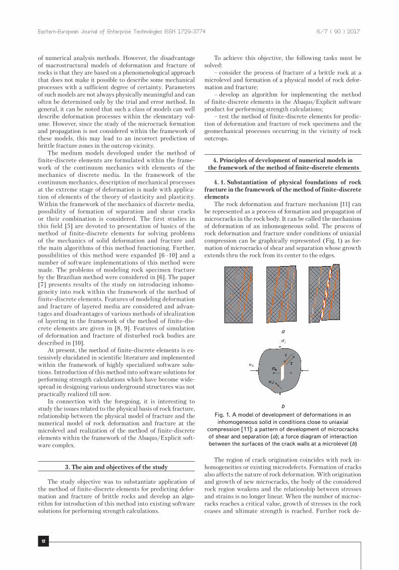
The rock deformation and fracture mechanism [11] can be represented as a process of formation and propagation of microcracks in the rock body. It can be called the mechanism of deformation of an inhomogeneous solid. The process of rock deformation and fracture under conditions of uniaxial compression can be graphically represented (Fig. 1) as for-mation of microcracks of shear and separation whose growth extends thru the rock from its center to the edges.
а
b
Fig.1.Amodelofdevelopmentofdeformationsinaninhomogeneoussolidinconditionsclosetouniaxial
compression[11]:apatternofdevelopmentofmicrocracksofshearandseparation(a);aforcediagramofinteractionbetweenthesurfacesofthecrackwallsatamicrolevel(b)
The region of crack origination coincides with rock in-homogeneities or existing microdefects. Formation of cracks also affects the nature of rock deformation. With origination and growth of new microcracks, the body of the considered rock region weakens and the relationship between stresses and strains is no longer linear. When the number of microc-racks reaches a critical value, growth of stresses in the rock ceases and ultimate strength is reached. Further rock de-
Applied mechanics
13
formation results in a break of residual bonds in the formed surface of slip or separation and attainment of the residual strength which is determined by friction of the surfaces of weakening. That is, individual rock particles interconnect through the contact surfaces which serve as cohesive sur-faces till the moment of fracture appears. Movement of such surfaces relative to each other is impossible until the collapse of these cohesive bonds occurs. The physical model consid-ered above has been adopted as a basis for development of numerical models of rock deformation and fracture in the framework of the method of finite-discrete elements. Like in the physical model, the process of rock deformation and fracture will be associated with the formation of microcracks in the rock body. Achievement of tensile or shear strength is the criterion for forming a crack inside the rock body.
4. 2. The algorithm for implementing the method of fi-nite-discrete elements into the Abaqus/Explicit software complex
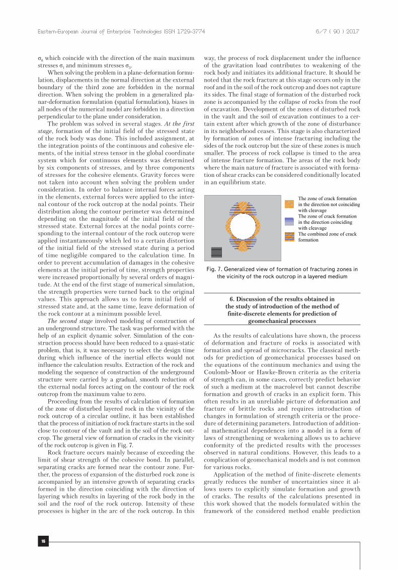
Construction of a numerical model within the framework of the method of finite-discrete elements involves several basic stages. The first stage consists in choosing or deriva-tion of equations of mechanical behavior of continuous and cohesive elements. The second stage involves generation of an elemental grid where continuous elements are separated from each other by cohesive elements (Fig. 2). Nodes of the continuous elements are not interconnected and force trans-fer between continuous elements occurs through cohesive elements. Such approach ensures continuity of displacements up to the moment of formation of the weakening surface and an individual deformation of the medium parts after formation of the weakening surface. The third stage involves development of a model of contact interaction between the faces of continuous elements ensuring a contact between the continuous surfaces after formation of the weakening surface (exclusion of the cohesive element from work). The third stage is the most difficult since the algorithm of finding contacts between newly formed surfaces should monitor po-sition in the process of problem solution and enable or disable the contact interaction in an automatic mode.
а b c
Fig.2.Examplesofageometricrepresentationofafiniteelementgridwithinthediscrete-continuousapproach:
flatdeformation(a);flatdeformationrealizedinaspatialformulation(b);generalizedspatialformulation(c)
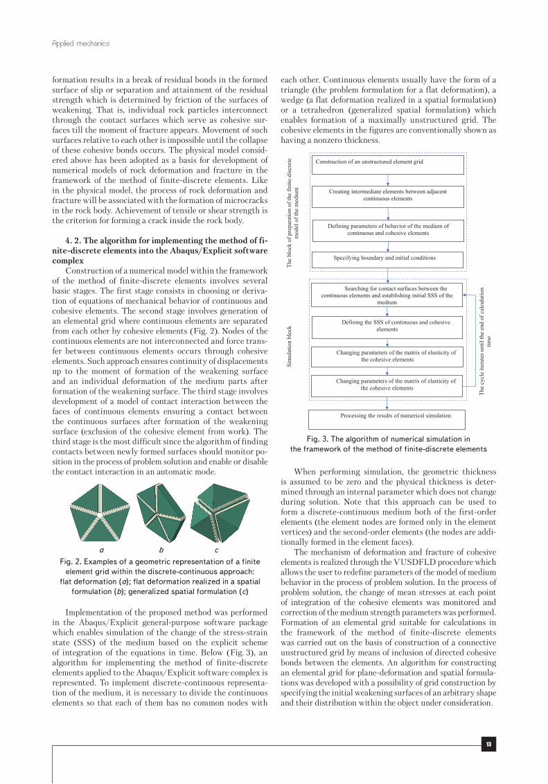
Implementation of the proposed method was performed in the Abaqus/Explicit general-purpose software package which enables simulation of the change of the stress-strain state (SSS) of the medium based on the explicit scheme of integration of the equations in time. Below (Fig. 3), an algorithm for implementing the method of finite-discrete elements applied to the Abaqus/Explicit software complex is represented. To implement discrete-continuous representa-tion of the medium, it is necessary to divide the continuous elements so that each of them has no common nodes with
each other. Continuous elements usually have the form of a triangle (the problem formulation for a flat deformation), a wedge (a flat deformation realized in a spatial formulation) or a tetrahedron (generalized spatial formulation) which enables formation of a maximally unstructured grid. The cohesive elements in the figures are conventionally shown as having a nonzero thickness.
Processing the results of numerical simulation
The
cycl
e ite
rate
s unt
il th
e en
d of
cal
cula
tion
time
Construction of an unstructured element grid
Creating intermediate elements between adjacent continuous elements
Defining parameters of behavior of the medium of continuous and cohesive elements
Specifying boundary and initial conditions
The
bloc
k of
pre
para
tion
of th
e fin
ite-d
iscr
ete
mod
el o
f the
med
ium
Si
mul
atio
n bl
ock
Searching for contact surfaces between the continuous elements and establishing initial SSS of the
medium
Defining the SSS of continuous and cohesive elements
Changing parameters of the matrix of elasticity of the cohesive elements
Changing parameters of the matrix of elasticity of the cohesive elements
Fig.3.Thealgorithmofnumericalsimulationintheframeworkofthemethodoffinite-discreteelements
When performing simulation, the geometric thickness is assumed to be zero and the physical thickness is deter-mined through an internal parameter which does not change during solution. Note that this approach can be used to form a discrete-continuous medium both of the first-order elements (the element nodes are formed only in the element vertices) and the second-order elements (the nodes are addi-tionally formed in the element faces).
The mechanism of deformation and fracture of cohesive elements is realized through the VUSDFLD procedure which allows the user to redefine parameters of the model of medium behavior in the process of problem solution. In the process of problem solution, the change of mean stresses at each point of integration of the cohesive elements was monitored and correction of the medium strength parameters was performed. Formation of an elemental grid suitable for calculations in the framework of the method of finite-discrete elements was carried out on the basis of construction of a connective unstructured grid by means of inclusion of directed cohesive bonds between the elements. An algorithm for constructing an elemental grid for plane-deformation and spatial formula-tions was developed with a possibility of grid construction by specifying the initial weakening surfaces of an arbitrary shape and their distribution within the object under consideration.

Eastern-European Journal of Enterprise Technologies ISSN 1729-3774 6/7 ( 90 ) 2017
14
5. Testing the application of the method of finite-discrete elements for solving the problems of geomechanics
The method of finite-discrete elements is applied for solving the problems of geomechanics where the process of extra-high deformation, fracture and fragmentation of the medium is of key importance. Implementation of this method in the Abaqus/Explicit software complex was tested on rock specimens subjected to a uniaxial and tri-axial compression and a tensile test. As an additional example, development of geomechanical processes in the vicinity of a circular tunnel in a layered medium was considered. Models in the framework of the method of finite-discrete elements were constructed taking into account the results of studies and recommendations presented in [7–9]. The results of labo-ratory rock tests used for comparison were obtained by the authors of [12].
5. 1. Prediction of stress-strain state for the speci-mens of isotropic homogeneous rock
A virtual experiment of testing a rock specimen in condi-tions of uniaxial compression was conducted in the following way. The model of the rock sample was assumed to be of a prismatic form, the specimen size was 80×80×160 mm. The virtual sample was placed on an absolutely rigid element simulating the supporting plate of the testing machine. The load on the front face of the virtual specimen was applied in a mode of specified strain through an absolutely rigid element simulating the loading plate. Special contact conditions were set between the faces of the virtual sample and the rigid elements. Coefficient of friction between the faces of the virtual sample and the rigid elements was assumed to be 0.05. This allowed us to practically eliminate the end effects on the stressed state of the specimen. In the triaxial tests, the same model was used as in the uniaxial compression, however a new boundary condition was introduced that simulates transfer of lateral pressure to the lateral surface of the sample.
The numerical experiment of testing a rock specimen for uniaxial compression along the generatrix was carried out un-der the following conditions. The model of the rock specimen was of cylindrical shape with dimensions of 80×80 mm. The load was applied through an absolutely rigid element to an area not exceeding 3 % of the total surface area of the speci-men. The loading was carried out up to fracture. To simplify and reduce dimensionality of the model, the potential fracture development site was determined in the model in advance.
As noted above, load on the samples under consideration was transmitted as a specified strain. At the same time, in or-der to reduce influence of inertial forces on the stress-strain state of the sample, displacement of the plate in the direction towards the face/lateral surface was assigned according to a definite law which can be represented in a general form as:
( ) ( )+a = + - x - x + x3 21 10 15 6 ;i i iA A A
+
-x =
-1
,i
i i
t tt t
where ti is initial value of the time period; ti+1 is the finite value of the time period; t is time at the moment of calcula-tion; Ai is the factor value corresponding to the initial period of time; Ai+1 is the factor value corresponding to the finite period of time.
Parameters of the model of rock behavior are summarized in Table 1. When simulation was performed, the strength of cohesive bonds was determined both by the value of strength of the cementation bonds and the internal friction between the rock particles.
Table1
Parametersoftherockmodel
The model parameters Value of indicator
Parameters of continuous madium
1. Deformation modulus, МPа 150
2. Coefficient of lateral strain 0.35
3. Density, kg/m3 2,200
Parameters of cohesive bonds
4. Bond stiffness in a normal direction, МPа 150,000
5. Bond stiffness in a tangential direction, МPа 30,000
6. Bond tensile strength, МPа 0.1
7. Bond shear strength, МPа 0.5
8. Energy of fracture, J/m2 10
Parameters of contact conditions between continuous elements after crack formation
9. Bond stiffness in a normal direction, МPа 150,000
10. Bond stiffness in a tangential direction, МPа 30,000
11. Coefficient of friction 0.3
Parameters of contact conditions between the loading plates and the specimen surface
12. Coefficient of friction 0.05
The patterns of deformation and fracture of rock spec-imens obtained by numerical simulation of the tests for uniaxial compression between flat plates and tension by compression along the generatrixes are shown in Fig. 4, a, b
The results of the triaxial compression tests are present-ed in Fig. 5, a.
a
b
Fig.4.Theresultsofcalculationofdeformationandfractureofarockspecimen:underconditionsofuniaxial
compression(a);splittingalongthegeneratrices(b)

Applied mechanics
15
а
b
Fig.5.Resultsofcalculationofdeformationandfractureofarockspecimenunderconditionsoftriaxialcompression:
deformationpattern(a)certificateoftherockstrength(b);theoreticalcertificateoftherockstrength(1);certificateofstrengthobtainedonthebasisoftestingtherockaccording
tothemethodoffinite-discreteelements(2)
The results of modeling the test of a rock sample in conditions of uniaxial compression and tension allow us to distinguish the following stages of deformation: the stage of ultimate deformation, the stage of achievement of the ulti-mate strength and the stage of strength loss at a deformation beyond the limits. A similar pattern of rock deformation was also observed by the results of laboratory tests. Achievement of the ultimate strength and the nature of material strength loss in simulation were determined by development of shear microcracks and separation in the rock specimen.
According to the results of numerical simulation of fracture of the rock specimen under conditions of triaxial compression, the character of its fracture was established. It is seen that the process of rock fracture is accompanied by formation of shear cracks and separation. The main crack is a shear crack. The resulting angle β of inclination of the main crack relative to the action of the main stresses is well correlated with the results of laboratory tests and obeys the classical condition β=45°+φ/2.
It should be noted that, despite the fact that the Cou-lomb-Moor criterion and the Rank’s criterion (Fig. 5, b) were accepted as strength conditions, the strength envelope obtained on the basis of modeling had a nonlinear form. This form of the strength envelope is characteristic of brittle rocks and is confirmed by numerous laboratory studies [11]. Thus, modeling of the rock fracture processes within the framework of the method of finite-discrete elements allows us to explicitly predict the process of rock fracture in the transition zone (the section between the uniaxial tensile
strength and the uniaxial compression strength) without specifying additional conditions.
The study results confirm efficiency of application of this method for modeling the processes of deformation and fracture of rocks. The strength and deformation properties of rocks obtained on the basis of numerical simulation corre-spond on the whole to the results of laboratory tests.
5. 2. Prediction of development of geomechanical pro-cesses in the vicinity of a circular tunnel in a layered medium
Numerical modeling of construction of a tunnel with radius r0 in layered media was carried out within the frame-work of the presented method of finite-discrete elements. The calculated area of the numerical model is divided into three zones (Fig. 6). The first zone of a size determined by a circle of radius r1 is designed for simulation of the processes of defor-mation and fracture of the layered medium in the rock body near the tunnel contour. The density of grid discretization in this area is maximal. Layers consisting of cohesive elements coincide with the direction of layering and form an inner layer filled with continuous elements interacting through cohesive elements. The size of this zone was taken not less than two expected dimensions of the limit-state region. The size of the zone of limit state can be determined on the basis of analytical or semi-empirical solutions or selected on the basis of iterative calculation. The strength properties of the cohesive elements depend on the angle ω. The second zone is a transitional region. In this zone, the elemental grid includes both continuous and cohesive elements. However, stiffness of the cohesive elements in this zone cannot degrade and the strength is equal to in-finity. Taking into account that stresses in this region are not expected to achieve the limit state, this assumption does not introduce any error in the results of the calculation and, at the same time, allows us to reduce calculation time. The third zone is intended for damping longitudinal and transverse waves and preventing their reflection from the external boundary of the numerical model back to the calculated region. Such a condition is attained by introduction of so-called “infinite” elements at the model boundary.
Fig.6.Geometricparameters,initialandboundaryconditionsofthenumericalmodeloftherockoutcropinalayeredmedium:thefirstzone,thezoneofelevatedgriddiscretizationdensity(1);thesecondzone,thetransitionzone(2);thethirdzone,thezoneofdampingofseismic
waves(infiniteelements)(3)
Stressed state of the rock body was determined through the components of vertical stresses σv and horizontal stresses
Eastern-European Journal of Enterprise Technologies ISSN 1729-3774 6/7 ( 90 ) 2017
16
σh which coincide with the direction of the main maximum stresses σ1 and minimum stresses σ3.
When solving the problem in a plane-deformation formu-lation, displacements in the normal direction at the external boundary of the third zone are forbidden in the normal direction. When solving the problem in a generalized pla-nar-deformation formulation (spatial formulation), biases in all nodes of the numerical model are forbidden in a direction perpendicular to the plane under consideration.
The problem was solved in several stages. At the first stage, formation of the initial field of the stressed state of the rock body was done. This included assignment, at the integration points of the continuous and cohesive ele-ments, of the initial stress tensor in the global coordinate system which for continuous elements was determined by six components of stresses, and by three components of stresses for the cohesive elements. Gravity forces were not taken into account when solving the problem under consideration. In order to balance internal forces acting in the elements, external forces were applied to the inter-nal contour of the rock outcrop at the nodal points. Their distribution along the contour perimeter was determined depending on the magnitude of the initial field of the stressed state. External forces at the nodal points corre-sponding to the internal contour of the rock outcrop were applied instantaneously which led to a certain distortion of the initial field of the stressed state during a period of time negligible compared to the calculation time. In order to prevent accumulation of damages in the cohesive elements at the initial period of time, strength properties were increased proportionally by several orders of magni-tude. At the end of the first stage of numerical simulation, the strength properties were turned back to the original values. This approach allows us to form initial field of stressed state and, at the same time, leave deformation of the rock contour at a minimum possible level.
The second stage involved modeling of construction of an underground structure. The task was performed with the help of an explicit dynamic solver. Simulation of the con-struction process should have been reduced to a quasi-static problem, that is, it was necessary to select the design time during which influence of the inertial effects would not influence the calculation results. Extraction of the rock and modeling the sequence of construction of the underground structure were carried by a gradual, smooth reduction of the external nodal forces acting on the contour of the rock outcrop from the maximum value to zero.
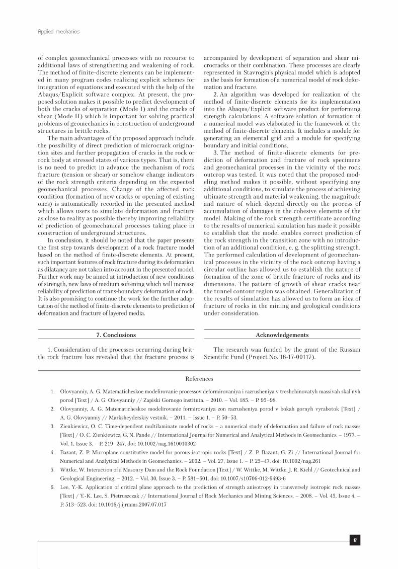
Proceeding from the results of calculation of formation of the zone of disturbed layered rock in the vicinity of the rock outcrop of a circular outline, it has been established that the process of initiation of rock fracture starts in the soil close to contour of the vault and in the soil of the rock out-crop. The general view of formation of cracks in the vicinity of the rock outcrop is given in Fig. 7.
Rock fracture occurs mainly because of exceeding the limit of shear strength of the cohesive bond. In parallel, separating cracks are formed near the contour zone. Fur-ther, the process of expansion of the disturbed rock zone is accompanied by an intensive growth of separating cracks formed in the direction coinciding with the direction of layering which results in layering of the rock body in the soil and the roof of the rock outcrop. Intensity of these processes is higher in the arc of the rock outcrop. In this
way, the process of rock displacement under the influence of the gravitation load contributes to weakening of the rock body and initiates its additional fracture. It should be noted that the rock fracture at this stage occurs only in the roof and in the soil of the rock outcrop and does not capture its sides. The final stage of formation of the disturbed rock zone is accompanied by the collapse of rocks from the roof of excavation. Development of the zones of disturbed rock in the vault and the soil of excavation continues to a cer-tain extent after which growth of the zone of disturbance in its neighborhood ceases. This stage is also characterized by formation of zones of intense fracturing including the sides of the rock outcrop but the size of these zones is much smaller. The process of rock collapse is timed to the area of intense fracture formation. The areas of the rock body where the main nature of fracture is associated with forma-tion of shear cracks can be considered conditionally located in an equilibrium state.
The zone of crack formation in the direction not coinciding with cleavage The zone of crack formation in the direction coinciding with cleavage The combined zone of crack formation
Fig.7.Generalizedviewofformationoffracturingzonesinthevicinityoftherockoutcropinalayeredmedium
6. Discussion of the results obtained in the study of introduction of the method of finite-discrete elements for prediction of
geomechanical processes
As the results of calculations have shown, the process of deformation and fracture of rocks is associated with formation and spread of microcracks. The classical meth-ods for prediction of geomechanical processes based on the equations of the continuum mechanics and using the Coulomb-Moor or Hawke-Brown criteria as the criteria of strength can, in some cases, correctly predict behavior of such a medium at the macrolevel but cannot describe formation and growth of cracks in an explicit form. This often results in an unreliable picture of deformation and fracture of brittle rocks and requires introduction of changes in formulation of strength criteria or the proce-dure of determining parameters. Introduction of addition-al mathematical dependences into a model in a form of laws of strengthening or weakening allows us to achieve conformity of the predicted results with the processes observed in natural conditions. However, this leads to a complication of geomechanical models and is not common for various rocks.
Application of the method of finite-discrete elements greatly reduces the number of uncertainties since it al-lows users to explicitly simulate formation and growth of cracks. The results of the calculations presented in this work showed that the models formulated within the framework of the considered method enable prediction
Applied mechanics
17
of complex geomechanical processes with no recourse to additional laws of strengthening and weakening of rock. The method of finite-discrete elements can be implement-ed in many program codes realizing explicit schemes for integration of equations and executed with the help of the Abaqus/Explicit software complex. At present, the pro-posed solution makes it possible to predict development of both the cracks of separation (Mode I) and the cracks of shear (Mode II) which is important for solving practical problems of geomechanics in construction of underground structures in brittle rocks.
The main advantages of the proposed approach include the possibility of direct prediction of microcrack origina-tion sites and further propagation of cracks in the rock or rock body at stressed states of various types. That is, there is no need to predict in advance the mechanism of rock fracture (tension or shear) or somehow change indicators of the rock strength criteria depending on the expected geomechanical processes. Change of the affected rock condition (formation of new cracks or opening of existing ones) is automatically recorded in the presented method which allows users to simulate deformation and fracture as close to reality as possible thereby improving reliability of prediction of geomechanical processes taking place in construction of underground structures.
In conclusion, it should be noted that the paper presents the first step towards development of a rock fracture model based on the method of finite-discrete elements. At present, such important features of rock fracture during its deformation as dilatancy are not taken into account in the presented model. Further work may be aimed at introduction of new conditions of strength, new laws of medium softening which will increase reliability of prediction of trans-boundary deformation of rock. It is also promising to continue the work for the further adap-tation of the method of finite-discrete elements to prediction of deformation and fracture of layered media.
7. Conclusions
1. Consideration of the processes occurring during brit-tle rock fracture has revealed that the fracture process is
accompanied by development of separation and shear mi-crocracks or their combination. These processes are clearly represented in Stavrogin’s physical model which is adopted as the basis for formation of a numerical model of rock defor-mation and fracture.
2. An algorithm was developed for realization of the method of finite-discrete elements for its implementation into the Abaqus/Explicit software product for performing strength calculations. A software solution of formation of a numerical model was elaborated in the framework of the method of finite-discrete elements. It includes a module for generating an elemental grid and a module for specifying boundary and initial conditions.
3. The method of finite-discrete elements for pre-diction of deformation and fracture of rock specimens and geomechanical processes in the vicinity of the rock outcrop was tested. It was noted that the proposed mod-eling method makes it possible, without specifying any additional conditions, to simulate the process of achieving ultimate strength and material weakening, the magnitude and nature of which depend directly on the process of accumulation of damages in the cohesive elements of the model. Making of the rock strength certificate according to the results of numerical simulation has made it possible to establish that the model enables correct prediction of the rock strength in the transition zone with no introduc-tion of an additional condition, e. g. the splitting strength. The performed calculation of development of geomechan-ical processes in the vicinity of the rock outcrop having a circular outline has allowed us to establish the nature of formation of the zone of brittle fracture of rocks and its dimensions. The pattern of growth of shear cracks near the tunnel contour region was obtained. Generalization of the results of simulation has allowed us to form an idea of fracture of rocks in the mining and geological conditions under consideration.
Acknowledgements
The research waa funded by the grant of the Russian Scientific Fund (Project No. 16-17-00117).
References
1. Olovyanniy, A. G. Matematicheskoe modelirovanie processov deformirovaniya i razrusheniya v treshchinovatyh massivah skal’nyh
porod [Text] / A. G. Olovyanniy // Zapiski Gornogo instituta. – 2010. – Vol. 185. – P. 95–98.
2. Olovyanniy, A. G. Matematicheskoe modelirovanie formirovaniya zon razrusheniya porod v bokah gornyh vyrabotok [Text] /
A. G. Olovyanniy // Marksheyderskiy vestnik. – 2011. – Issue 1. – P. 50–53.
3. Zienkiewicz, O. C. Time-dependent multilaminate model of rocks – a numerical study of deformation and failure of rock masses
[Text] / O. C. Zienkiewicz, G. N. Pande // International Journal for Numerical and Analytical Methods in Geomechanics. – 1977. –
Vol. 1, Issue 3. – P. 219–247. doi: 10.1002/nag.1610010302
4. Bazant, Z. P. Microplane constitutive model for porous isotropic rocks [Text] / Z. P. Bazant, G. Zi // International Journal for
Numerical and Analytical Methods in Geomechanics. – 2002. – Vol. 27, Issue 1. – P. 25–47. doi: 10.1002/nag.261
5. Wittke, W. Interaction of a Masonry Dam and the Rock Foundation [Text] / W. Wittke, M. Wittke, J. R. Kiehl // Geotechnical and
Geological Engineering. – 2012. – Vol. 30, Issue 3. – P. 581–601. doi: 10.1007/s10706-012-9493-6
6. Lee, Y.-K. Application of critical plane approach to the prediction of strength anisotropy in transversely isotropic rock masses
[Text] / Y.-K. Lee, S. Pietruszczak // International Journal of Rock Mechanics and Mining Sciences. – 2008. – Vol. 45, Issue 4. –
P. 513–523. doi: 10.1016/j.ijrmms.2007.07.017
Eastern-European Journal of Enterprise Technologies ISSN 1729-3774 6/7 ( 90 ) 2017
18
7. Munjiza, A. Combined single and smeared crack model in combined finite-discrete element analysis [Text] / A. Munjiza,
K. R. F. Andrews, J. K. White // International Journal for Numerical Methods in Engineering. – 1999. – Vol. 44, Issue 1. – P. 41–57.
doi: 10.1002/(sici)1097-0207(19990110)44:1<41::aid-nme487>3.0.co;2-a
8. Mahabadi, O. K. Numerical modelling of a Brazilian disc test of layered rocks using the combined finite-discrete element method
[Text] / O. K. Mahabadi, G. Grasselli, A. Munjiza // Proceedings of the 3rd CanadaeUS (CANUS) Rock Mechanics Symposium
(RockEng09). – 2009. – P. 412–423.
9. Mahabadi, O. K. A novel approach for micro-scale characterization and modeling of geomaterials incorporating actual material
heterogeneity [Text] / O. K. Mahabadi, N. X. Randall, Z. Zong, G. Grasselli // Geophysical Research Letters. – 2012. – Vol. 39,
Issue 1. doi: 10.1029/2011gl050411
10. Lisjak, A. Continuum-discontinuum analysis of failure mechanisms around unsupported circular excavations in anisotropic clay
shales [Text] / A. Lisjak, G. Grasselli, T. Vietor // International Journal of Rock Mechanics and Mining Sciences. – 2014. – Vol. 65,
Issue 96–115. doi: 10.1016/j.ijrmms.2013.10.006
11. Lisjak, A. Numerical Modelling of the Anisotropic Mechanical Behaviour of Opalinus Clay at the Laboratory-Scale Using FEM/
DEM [Text] / A. Lisjak, B. S. A. Tatone, G. Grasselli, T. Vietor // Rock Mechanics and Rock Engineering. – 2012. – Vol. 47,
Issue 1. – P. 187–206. doi: 10.1007/s00603-012-0354-7
12. Gordeev, V. A. Primenenie metoda konechno-diskretnyh ehlementov dlya prognozirovaniya deformaciy gornyh vyrabotok [Text] /
V. A. Gordeev, B. T. Il’yasov // Innovacionnye geotekhnologii v gornom dele. – Ekaterinburg, 2015. – P. 98–101.
13. Il’yasov, B. T. Modelirovanie dlitel’nogo razrusheniya massivov gornyh porod metodom konechno-diskretnyh ehlementov [Text] /
B. T. Il’yasov // Marksheyderskiy vestnik. – 2016. – Issue 1. – P. 48–52.
14. Stavrogin, A. N. Ehksperimental’naya fizika i mekhanika gornyh porod [Text] / A. N. Stavrogin, B. G. Tarasov. – Sankt-Peterburg:
Nauka, 2001. – 343 p.
15. Stavrogin, A. N. Prochnost’ gornyh porod i ustoychivost’ vyrabotok na bol’shih glubinah [Text] / A. N. Stavrogin, A. G. Protosenya. –
Moscow: Nedra, 1985. – 271 p.
16. Stavrogin, A. N. Plastichnost’ gornyh porod [Text] / A. N. Stavrogin, A. G. Protosenya. – Moscow: Nedra, 1979. – 301 p.
17. Karasev, M. A. Investigating Mechanical Properties of Argillaceous Grounds in Order to Improve Safety of Development of
Megapolis Underground Space [Text] / M. A. Karasev // International Journal of Applied Engineering Research. – 2016. –
Vol. 11. – P. 8849–8956.