Embed Size (px)
Citation preview

2014 VOL. 60 NO.167 Hydro Static Transmission Forklift Models FH60-1, FH70-1, and FH80-1
― 1 ―
Introduction of Products
Hydro Static Transmission Forklift Models FH60-1, FH70-1, and FH80-1
Hiroshi Yamamoto
Takehito Shinbashi
Satoshi Takahara
The 6-8 ton class engine-powered forklift trucks, FH60-1, FH70-1, and FH80-1, have been developed and introduced into the market as larger capacity trucks of the FH series. Previous models FH35-1, FH40-1, FH 45-1, and FH 50-1 are Komatsu’s first forklift trucks that are equipped with an electronically controlled hydrostatic transmission and a closed-center load sensing system with a variable pump. Based on Komatsu’s hydraulic technologies, the FH60-1, FH70-1, and FH80-1 have been greatly improved over the existing models. This paper describes the new technologies introduced in the new FH60-1, FH70-1, and FH80-1 models.
Key Words: Forklift, Electronically controlled hydrostatic transmission, Closed-center load sensing system, Multi-monitor, KOMTRAX, Low fuel consumption, Environment, Safety, ICT
1. Introduction
With the increased global awareness of environmental
problems and higher crude oil prices in recent years, demands
for low fuel consumption and reduced environmental load are
rapidly increasing. To meet these demands, we set out to
develop medium-sized forklift trucks that use a hydrostatic
transmission, and brought to market the 4-5 ton class
engine-powered forklift trucks FH40/45/50-1 in July 2012.
(Model FH35-1 was added in July 2013.) FH35/40/45/50-1
has been highly rated in the market for the great
improvements in fuel consumption and operability.
To expand the lineup of the FH series with larger
capacity models, we have developed 6-8 ton class forklift
trucks. Based on the high rating of the electronically
controlled hydrostatic transmission in the market, we have
brought into the market the FH60/70/80-1, which feature
improved operability. These models are outlined below (Fig.
1, Table 1).
Fig. 1 FH80-1
2014 VOL. 60 NO.167 Hydro Static Transmission Forklift Models FH60-1, FH70-1, and FH80-1
― 2 ―
Table 1 Major specifications
Item Unit New model FH80-1
Current modelFD80-10
Performance and dimensions
Maximum load kg 8000 8000 Load center mm 600 600 Maximum travel speed km/h 23.5 31
Wheelbase mm 2300 2300 Tread (front wheels/rear wheels) mm 1540/1640 1540/1640
Vehicle weight kg 11280 10910
Engine
Manufacturer - Komatsu Komatsu Model - SAA4D95LE-6 SAA4D95LE-5No. of cylinders/Total displacement -/cc 4/3260 4/3206
Rated net output kW/rpm 63.9/2150 69.0/2250 Fuel tank capacity L 177 140
Information ICT - KOMTRAX -
Fuel consumption
In-house standard course A (Comparison with current model)
- 70 100
2. Aims of Development and Approach
(1) Compliance with emission regulations
• Complies with the Japanese emission regulations (Tier 4
Interim) in 2011.
(2) Up to 30% reduction in fuel consumption (as compared
with the current FD80-10 model).
• Reduces power transmission losses by introducing an
electronically controlled hydrostatic transmission.
• Achieves low fuel consumption in high-load work by
controlling engine output according to the weight of load.
• Reduces hydraulic pressure losses when operating work
equipment while driving the vehicle by introducing a
closed-center load sensing system with a variable pump.
(3) Improvement in drivability and operability
• Improves drivability by introducing an electronically
controlled hydrostatic transmission.
• Improves operability in creepless driving, starting on
slope, and switching back.
• Improves inching performance for work in harbors and
container work. (*)
• Reduces operating force using proportional pressure
control for work equipment. (*)
• Improves holding performance by improving the
operator’s seat. (*)
(4) Improvement in safety
• A travel speed limiting function is equipped as standard.
• Adds a seat belt caution display. (*)
(5) ICT
• Improves visibility and functionality with a color LCD
multi-monitor.
• Improves KOMTRAX, which was introduced in the FH
series as standard. (*)
(*): First introduced in the FH60-1, FH70-1, and FH80-1.
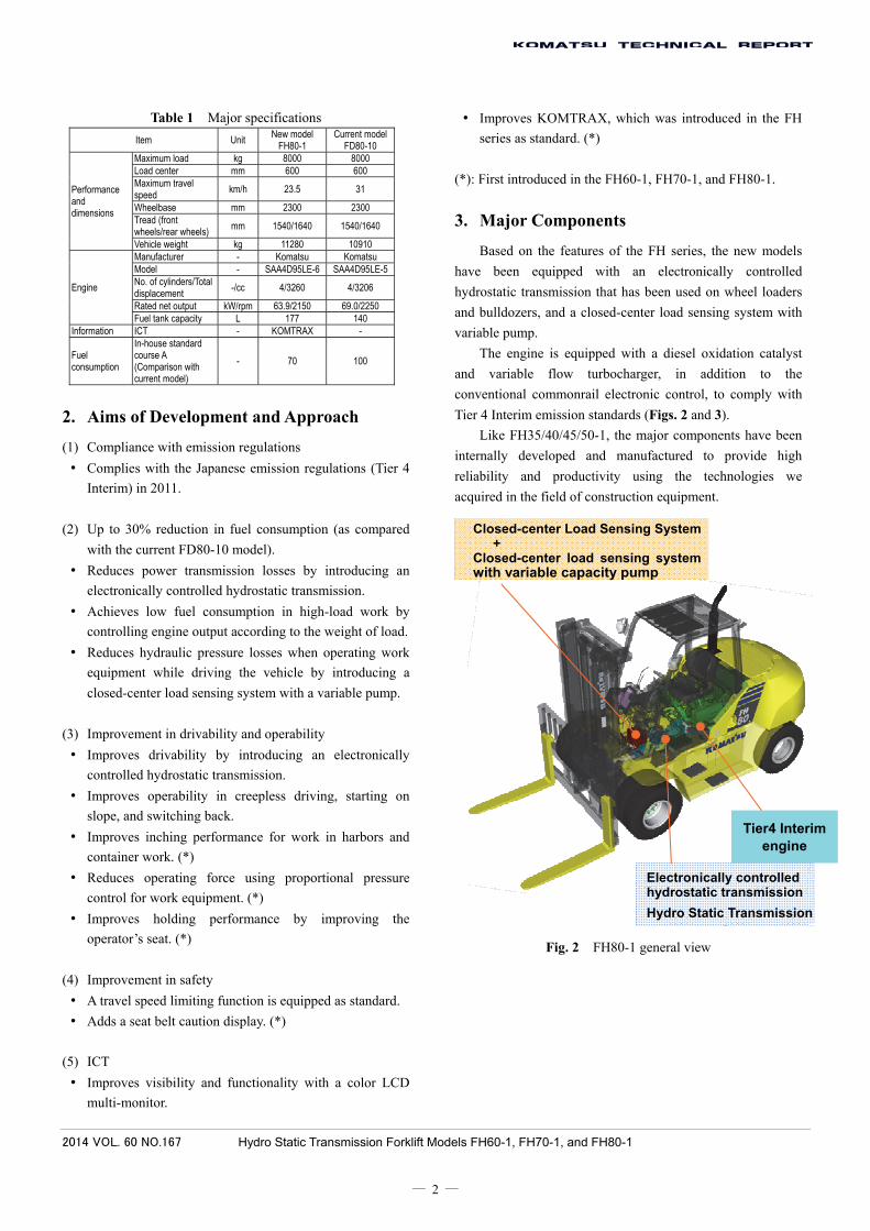
3. Major Components
Based on the features of the FH series, the new models
have been equipped with an electronically controlled
hydrostatic transmission that has been used on wheel loaders
and bulldozers, and a closed-center load sensing system with
variable pump.
The engine is equipped with a diesel oxidation catalyst
and variable flow turbocharger, in addition to the
conventional commonrail electronic control, to comply with
Tier 4 Interim emission standards (Figs. 2 and 3).
Like FH35/40/45/50-1, the major components have been
internally developed and manufactured to provide high
reliability and productivity using the technologies we
acquired in the field of construction equipment.
Fig. 2 FH80-1 general view
Tier4 Interimengine
Electronically controlled hydrostatic transmission
Hydro Static Transmission
Closed-center Load Sensing System + Closed-center load sensing system with variable capacity pump

2014 VOL. 60 NO.167 Hydro Static Transmission Forklift Models FH60-1, FH70-1, and FH80-1
― 3 ―
Fig. 3 Major components
4. System Overview
4.1 System configuration of FH60/FH70/FH80
Fig. 4 System configuration of electronically controlled
hydrostatic transmission vehicles
Fig. 4 shows the system configuration of electronically
controlled hydrostatic transmission vehicle models
FH60/70/80-1. This configuration is similar to that of
FH35/40/45/50-1.
The engine drives the pump to generate hydraulic
pressure, which is converted back to a rotational force by the
motor. Changing the angle of the swash plate that is
connected to the pistons changes the piston stroke, which
continually increases or decreases the flow rate of hydraulic
oil to control the travel speed. Thus, stepless control from
normal rotation to stopping and reverse rotation can be
performed by changing the swash plate angle. The neutral
swash plate position stops the stroke of the pistons, generating
the same effect as applying the brake.
The inching and accelerator pedals send electronic
signals to the controller, which outputs EPC current to the
pump and motor based the specified conditions so that the
pump and motor capacities are determined according to the
operator’s intention.
A variable pump is also used in the hydraulic system for
the work equipment so that the required amount of oil is
supplied based on signals from the control valve.
5. Reduction in Fuel Consumption
5.1 How forklift trucks are used Forklift trucks are often used in limited spaces where
acceleration, stopping, switching between forward and reverse
travels, and simultaneous load handling and vehicle travel
occur frequently. Such uses are more common on sites
handling high load with a high operating ratio (such as in
recycle businesses), where fuel consumption tends to be
greater and users are more interested in reduction in fuel
consumption. Taking into consideration such work sites where
low fuel consumption gives a great benefit to users, the
following technologies are used to achieve low fuel
consumption.
Fig. 5 Example of high load work of forklift truck
5.2 Technologies for low fuel consumption (1) Reduction of heat losses and slip losses
In simultaneous load handling and travel operations of a
torque converter equipped vehicle, the inching pedal is used
to adjust clutch slip and control travel speed, which generates
clutch slip losses and heat losses.
On hydraulic drive vehicles, on the other hand, since
Inching pedal
Accelerator pedal
Drive axle
Tire
Motor
Hydrostatic transmission
Pump
Controller
Engine
Pressure sensor
PPC valve
Swash plate
Work equipment
Control valve
Variable pump
Commonrail electronically controlled engine
Hydraulic pump for traveling
Hydraulic motor for traveling
Drive axle
Charging pump (Hydraulic drive and brake)
Work equipment pump
Diesel oxidation catalyst
Recycle business (paper)

2014 VOL. 60 NO.167 Hydro Static Transmission Forklift Models FH60-1, FH70-1, and FH80-1
― 4 ―
travel speed is controlled by changing the pump swash plate
angle to change the flow rate of oil, instead of slipping the
clutch, heat or slip losses do not occur, achieving low fuel
consumption.
(2) High efficiency in low speed ranges
The torque converter (3-element/1-speed/2-phase)
generally used in forklift trucks provides high efficiency in
high-speed ranges because of a free wheeling, but suffer from
large agitation losses in low-speed ranges, resulting in lower
efficiency than the hydraulic drive system (Fig. 6).
Although hydraulic drive vehicles provide better
acceleration for traveling, the engine is controlled to restrict
rev-up, thus reducing fuel consumption during acceleration
without sacrificing travel performance.
Fig. 6 Travel efficiency
(3) Optimizing engine output
Using measures (1) and (2) described above, the
maximum engine output was reduced by approximately 8
percent from the conventional torque converter equipped
vehicles, resulting in lower fuel consumption.
(4) Low-speed matching
In general, the fuel consumption ratio is lower near the
engine speed where the maximum torque is obtained than that
near the rated engine speed.
The hydraulic pump’s absorption torque matching point
with respect to the engine has been set closer to the maximum
torque from the torque converter’s absorption torque. This has
allowed the range with low fuel consumption to be used for a
long time during acceleration, contributing to low fuel
consumption ( in Fig. 7).
(5) Shifting engine torque curve at no load
There is a great difference in vehicle weight between
when a forklift truck is carrying a load (loaded condition) and
not carrying a load (unloaded condition). On FH35/40/45/
50-1, the weight of a load is detected by a sensor to restrict
engine output at light load conditions, thus reducing fuel
consumption. We have improved it a step further on
FH60/70/80-1 and implemented stepless control of engine
output according to load, achieving even lower fuel
consumption ( in Fig. 7).
Fig. 7 Matching with engine
(6) Closed-center load sensing system with variable pump
The hydraulic system for work equipment in forklift
trucks typically uses a gear pump (fixed capacity), which
supplies more amount of oil than necessary, creating
hydraulic losses.
The same as FH35/40/45/50-1, FH60/70/80-1 uses a
closed-center load sensing system with a variable pump. By
keeping the pressure difference between the pump delivery
pressure and the required pressure of each work equipment
constant, the necessary amount of oil is supplied, thus
reducing hydraulic losses (Fig. 8).
Engine torque curve
Hydraulic pump absorption torque
④
Stepless engine output control according to load
Full (heavy load)
Derate (light load) ⑤
Eng
ine
torq
ue (
kg-m
)
Engine speed (rpm)
Torque converter absorption torque
1st speed
Eff
icie
ncy 2nd speed
Hydraulic drive
T/C 1st speed
T/C 2nd speed
Hydraulic drive
Travel speed (km/h)

2014 VOL. 60 NO.167 Hydro Static Transmission Forklift Models FH60-1, FH70-1, and FH80-1
― 5 ―
Fig. 8 Reduction of hydraulic losses in work equipment
6. Results
6.1 Reduction in fuel consumption Fig. 9 shows the reduction in fuel consumption on
in-house standard courses.
A significant reduction in fuel consumption has been
attained (up to approximately 30%) not only on the high-load
course (A), which requires frequent switching back at short
distances to simulate loading work on trucks, but also on the
low- to medium-load course (B).
Fig. 10 shows the frequency distribution of engine speed
and torque on the high-load course (A). The larger a circle,
the greater the distribution. The smaller circles are shifted to
the low fuel consumption side as compared with previous
models. In particular, changes in the engine speed are small
during acceleration, which allowed the low fuel consumption
range to be used over a long period of time, achieving the
desired reduction in fuel consumption.
Fig. 9 Comparison of fuel consumption on in-house
standard courses
FD80-10 (Torque converter equipped vehicle) Current model
FH80-1 (Hydrostatic transmission vehicle) New model
Fig. 10 Frequency distribution and fuel consumption map on
high-load course
6.2 Improvement in drivability and operability
The electronically controlled hydrostatic transmission
introduced in FH35/40/45/50-1 continuously controls the
swash plate, allowing forward and reverse travels to be
switched smoothly even stepping on the accelerator pedal
without applying the brake to stop the vehicle. The
transmission also produces a braking effect during the neutral
swash plate position, which minimizes sliding down on slopes,
reducing operator’s fatigue. These benefits have gained high
evaluation particularly among users in the paper industry.
FH60/70/80-1 trucks, which have a similar user base, are also
expected to be well-received.
Users engaged in harbor-related work have been
requesting the improvement in drivability in inching travel at
0 to 0.5 km/h for higher efficiency in loading containers. The
0
5
10
15
20
25
30
35
40
kgm
0
5
10
15
20
25
30
35
40
kgm
Fue
l con
sum
ptio
n [L
/h]
Course A Course B
Current model New model
Circuit with fixed pump
Circuit with
variable pump
Reduc- tion of
hydrau-lic
losses
Loss during relief Loss at neutral
Required flow rate Flow rate Reduced loss
Pump pressure
Var
iabl
e pu
mp
Fix
ed
pum
p
Required flow rate Required flow rate
Total delivery Total delivery Total delivery
Pump pressure
Reduced loss V
aria
ble
pum
p
Fix
ed
pum
p
Flow rate Reduced
loss
Var
iabl
e pu
mp
Fix
ed
pum
p
Lever input
Engine speed [rpm]
Engine speed [rpm]
Eng
ine
torq
ue [k
g-m
] E
ngin
e to
rque
[kg-
m]
High frequency in high speed range
High frequency in maximum torque range
Engine torque curve
Engine torque curve
Equal fuel consumption curve [L/h]
Equal fuel consumption curve [L/h]
Loss during fine control

2014 VOL. 60 NO.167 Hydro Static Transmission Forklift Models FH60-1, FH70-1, and FH80-1
― 6 ―
FH60/70/80-1 has incorporated the improvement in
acceleration and inching control in low speed ranges (Fig.
11).
FH35 to 50-1 Slightly stepping on the acceleration
pedal causes EPC current to
increase the pump capacity, starting
the vehicle.
On FH35/40/45/50-1, there is a delay in vehicle response
during inching start, causing a delay in moving the vehicle off.
As a result, operators tend to step on the accelerator pedal
further, causing to start quicker. FH60/70/80-1 has employed
feedback control in the inching speed range to reduce the
delay in vehicle response. This has improved starting and low
speed travel performances in lower speed ranges.
FH60/70/80-1 [Feedback control has been added in
inching speed range only.]
Fig. 11 Control in low speed ranges
Other improvements
• The deceleration when the accelerator pedal is released in
low vehicle speed ranges has been increased so that the
vehicle can be stopped only by releasing the accelerator
pedal.
• The hydraulic drive power is retained during
simultaneous operation (i.e. the accelerator and inching
pedals are stepped on simultaneously) in inching so that
the vehicle can be smoothly stopped using the mechanical
brake.
These improvements have allowed for adjustment from
inching start to stopping, thus dramatically improving
drivability at inching speeds for container work in harbors in
particular.
Since a hip support design is used in the conventional
operator’s seat, large operators often feel the sitting space is
too tight. On FH60/70/80-1, the operator’s seat has been
changed to a waist support design with good hold and wider
seating surface so that large operators can be seated
comfortably.
Fig. 12 New operator’s seat
6.3 Safety A travel speed limit function is equipped as standard,
which allows the maximum travel speed to be limited at four
levels to work in a confined space or to fit the specified speed
limit in a factory.
Fig. 13 Four levels of maximum speed settings
For additional safety, a seat belt switch has been added to
alert the operator not wearing the seat belt.
Tra
vel s
peed
(km
/h)
Acceleration is controlled based on specified travel speed for moving off
Speed setting (23.5km/h)
Speed setting: 15 km/h
Speed setting: 8 km/h
Time (t)
Speed setting: 5 km/h
Waistsupport
14% increased Seat belt switch added
Hipsupport
FH35 to 50-1
FH60/70/80-1
Large delay in vehicle response
Accelerator opening
EPC current
Time (sec)
Small delay in vehicle response
Travel speed (km/h) (0.1km/h)
Travel speed (km/h) (0.3km/h)
Accelerator opening
EPC current
Time (sec)
Acceleration pedal (Pedal opening)
EPC control current
Hydraulic pump capacity
Vehicle speed sensor PID control Travel speed
Additional
+ -
+ +
Acceleration pedal EPC control current
Travel speed
Hydraulic pump capacity

2014 VOL. 60 NO.167 Hydro Static Transmission Forklift Models FH60-1, FH70-1, and FH80-1
― 7 ―
6.4 ICT (Information and Communications Technology)
FH60/70/80-1 is equipped with 3.5-inch color LCD
multi-monitor, which greatly improves the visibility of
vehicle information (Fig. 13). In addition, a speedometer and
load meter, which were optional equipment on previous
models, are provided as standard for greater functionality.
FH35/40/45/50-1 models first introduced KOMTRAX as
standard equipment as forklift trucks for visualization of
information such as position, operating status, and fuel
consumption. FH60/70/80-1 are equipped with a further
improved KOMTRAX, which provides greater support for
operators with information on actual operation hours and fuel
consumption during that period, as well as operator
identification using ID keys provided as an option.
Fig. 13 Color LCD multi-monitor
7. Conclusion
FH35/40/45/50-1, equipped with a hydrostatic
transmission and closed-center load sensing system, have
become one of the most successful Komatsu products. With a
view to expanding the lineup of the FH series into the 6-8 ton
class, we have developed the FH60/70/80-1 as further
advanced models with the addition of various new features.
We will promote the evolution and growth of the FH series to
provide attractive products that meet the needs of the market.
Introduction of the writers
Hiroshi Yamamoto
Joined Komatsu Ltd. in 1984.
Currently a member of the Utility
Development Center, Development Division.
Takehito Shinbashi
Joined Komatsu Ltd. in 1998.
Currently a member of the Utility
Development Center, Development Division.
Satoshi Takahara
Joined Komatsu Ltd. in 1991.
Currently a member of the Utility
Development Center, Development Division.
[A few words from writers]
By further improving the features of FH35/40/45/50-1
models which have been highly praised in the market, we have
developed more sophisticated forklift trucks through close
cooperation with other development centers, related divisions in
the factory, and testing centers.
In addition, the features described in this paper have also
been introduced to the 3.5-5 ton class models, and the new
FH35/40/45/50-2 models that conform with Tier 4 Final have
been released at the same time.
It is our pleasure if those seven models including the new
FH60-1, FH70-1, and FH80-1 could contribute to the sales
expansion of Komatsu forklift trucks and further satisfaction of
users.
SMR/Clock/Odometer
Warningdisplay
Speedometer OPD→STD
Hydraulic oil temperature
gauge
New functions
Fuel consumption meter (average fuel consumption)/Load meter(switching display)
Eco gauge (momentary fuel consumption)
Fuel gauge
Travel speed limit ON/OFF switch
FNR lever position
Coolant temperature
gauge
Seat belt alert