Embed Size (px)
Citation preview

Introduction of Product
Introduction of PC18MR-2
Shinichi Umeda
Takenobu Ando
Katsumi Yokoo
Sachio Shimizu
The zero tail swing mini-shovel PCMR-1 has undergone a full model change and has been put on the market as Model PC18MR-2 as a global model, as reported below.
Key Words: compact hydraulic excavator, MR-2, two-pole ROPS canopy, ROPS cab, floor tilt-up mechanism,
variable guage
1. Introduction The conventional machine PC15MR-1 featuring high stabil-
ity and operability enjoyed a good reputation in the Japanese market. In markets overseas, however, an improvement in operator comfortability has been desired for operators with a large build.
Responding to these requests, the PC18MR-2 has been developed as a model change vehicle of PC15MR-1 and has been introduced to the market. In U.S.A. and Japan, the new model was instroduced as a successor of PC15MR-1 while in Europe the model was introduced as a new zero tail swing machine of this class (Table 1, Photo 1).
Table 1 Principal Specification
Item Unit PC18MR-2 PC15MR-1Machine weight kg 1640 1590 Rated output kW/rpm 11.2/2600 11.2/2600Standard bucket capacity (JIS standard) m3 0.044 0.044
Hi km/h 4.3 4.3 Travel speed
Lo km/h 2.3 2.3 Maximum digging depth mm 2160 2155 Maximum digging radius mm 4025 3900
Photo 1 PC18MR-2
2006 ① VOL. 52 NO.157 Introduction of PC18MR-2
― 1 ―

2. Aim of Development In response to needs inside and outside of Japan, the new
model has been developed to incorporate the same catchphrases of PC20-50MR-2, “safety, roominess, soundness” as development concepts.
Table 2 Development concepts
Principal selling points (Development concepts) Item Feature
Two-pole ROPS canopy Conformance to ultra low noise regulation of the Japanese Land and Infrastructure Ministry, EU new tier noise regulation Conformance with Tier-2 exhaust gas regulations Lock lever that locks entire operations Retractable seat belt
Safety
Engine neutral start mechanism Larger operator seat space Easier getting into and alighting from seat (walkthrough)
Roomi-ness
Larger space around a seat Floor tilting up structure Full open structure 500 hour interval between maintenance services Metal plates as exterior machine covers
Sound-ness
Less loosening of pin play of work equipment
2006 ① VOL. 52 NO.157 Introduction
― 2
of PC18MR-2
―
3. Principal Features
3.1 ROPS cab The European-specification equipment can now mount a cab
to meet the needs in Europe for a cab (No cab mounting for U.S.A. or Japan). Through a review of the machine body layout and design of the revolving frame matching the cab profile as described below, a cab could be mounted for the first time in the world as a zero tail swing machine of this class.
The cab adopts a round sliding door that can be opened and closed even at a narrow site and it complies with ROPS (Fig. 1).
Fig. 1 PC18MR-2 equipped with cab
3.2 Features of PC18MR-2 (variable gauge) The structure of the variable gauge was reviewed with
PC18MR-2 to install a cab. The conventional machine PC15MR-1 had a link-type structure. In case of this structure and if the distance between the legs is small, this leg structure would cause “falling forward” of the equipment that is installed with a cab and whose center of gravity is high, after the side frame moves back and forth. The PC18MR-2 has a sliding-type structure to prevent this (Fig. 2).
PC15MR-1
PC18MR-2
Fig. 2 Variable leg structure
3.3 Common features with MR-2 The following features are common with the upper models
of MR-2 (PC20 to 50MR-2). (1) Operator seat space largest for class
In the past, the operator space in mini-excavators has been small, sometimes forcing the operator to endure discomfort. The space has been small especially for operators with a large build exceeding 170cm in height.
In a market survey undertaken in Europe and U.S.A. prior to the development work, the first request item for improvement was an expansion of the operator space. More space around the feet especially was desired and this was accomplished by taking the following actions (Fig. 3).

Center of swing
Areas expanded compared with existing machines
Unit PC18MR-2 PC15MR-1 PC78US-6 Width mm 960 780 940 Depth mm 576 456 600
Space around feet Width×depth cm2 5530 3557 5640
Fig. 3 Comparison of space around feet
1) The machine body layout was reviewed and the fuel tank that was placed in the space around the right foot was moved to the rear of the machine body. Instead, the fuel tank is mounted on a counterweight and more space is now provided (Fig. 4).
Counterweight
Fuel tank
Fig. 4 Fuel tank mounted on counterweight
2) The 2nd speed pedal was eliminated by adopting an
automatic gear shift mechanism for traveling. 3) Easier getting into and getting out of the cab through a
change in canopy structure (Described later)
(2) Two pole ROPS canopy The conventional machines came with two types of canopy,
namely, the TOPS (mini-excavator protective structure at turning over) canopy and the so-called dual-foot soft canopy. The TOPS canopy had four poles and was inferior to the soft canopy in “easier getting into and getting out of the cab” and “visibility.”
The TOPS canopy was less accepted in areas that had no
regulations on visibility and other items. The new model was developed based on the following
concepts. 1) To safeguard the operator against falling of foreign mate-
rial and machine roll-over regardless of whether or not regulations were enforced.
2) To avoid any additional cost to the customers for remodel-ing accomplished to meet new regulations in case stricter regulations are enforced in the future.
3) To develop and provide as a standard specification a two-pole ROPS (roll-over protective structure) canopy to satisfy “easier getting into and getting out of the cab” and “visibility” to render remodeling after resale unnecessary when machines are resold to overseas markets. These two features are common, standard specifications throughout the world.
The canopy base is forged and has sufficient strength as a ROPS canopy, meeting both design and productivity perform-ance (Photo 2). Pipe Forging (Base)
Photo 2 ROPS canopy Tuned to the installation of a ROPS canopy, a seat belt is
now supplied as a standard specification. The seat belt is retractable for operator convenience (Fig. 5).
Fig. 5 Retractable seat belt
Retractable seat belt
(3) Floor tilting up structure for drastic improvement in
accessibility Mini-excavators do not provide much space in machine
bodies, making it difficult to access the floor during inspection or repairs. In the rental business, which is a large segment of the market, mini-excavators are constantly serviced for mainte-nance or repairs and an improvement in their accessibility
2006 ① VOL. 52 NO.157 Introduction of PC18MR-2
― 3 ―
greatly reduces user inconvenience. The floor tilting up structure has been adopted to make field
maintenance and repair servicing easier and to reduce man hour and cost in servicing for maintenance and repairs (Photo 3).
Photo 3 Floor tilted up This structure makes it easier for maintenance servicing and
part replacement, which have been troublesome in the conventional machines, of heavy components such as the engine, swing motor and swivel joint. It also allows visual checks of piping and wiring to enhance their reliability.
The floor tilting up structure offers the following features. • Tilting fulcrum placed in front part of floor (By adopting a rubber bushing, floor vibration is
reduced.) • A combination of a gas spring and torsion bar makes the
operating force constant. A double lock is adopted for locking of the floor tilting up
function to ensure operator safety (Fig. 6). • Automatic locking mechanism • Locking by pin plugging
Automatic lock
Plug pin
Fig. 6 Locking device when floor is tilted up
(4) Other features 1) Environmental friendliness
The noise specification conforms to the ultra low noise regulation of the Japanese Land and Infrastructure Ministry.
The exhaust gas specification meets the tier-2 exhaust gas regulations of U.S.A., Europe and Japan. 2) Safety of operation system
All the actuators are adopted with PPC control to lock all actuators by operating the lock lever.
The engine can be started only when the lock lever is locked. 3) Exterior machine covers
The side deck is made of a casting that is integral to the revolving frame to resist damage when a shock is applied. All the exterior machine covers are made of metal plates to greatly enhance repairability.
Only the engine hood can be opened and closed on the conventional machine. The new model allows opening and closing of both left and right side covers also. 4) 500 hours between maintenance services
The interval between periodical maintenance servicing has been lengthened to 500 hours, to save on maintenance servicing time for the customers. 5) Less loosening of pin play of work equipment
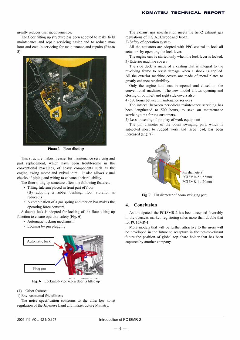
The pin diameter of the boom swinging part, which is subjected most to rugged work and large load, has been increased (Fig. 7).
Pin diameters PC18MR-2:55mm PC15MR-1:50mm
Fig. 7 Pin diameter of boom swinging part
4. Conclusion As anticipated, the PC18MR-2 has been accepted favorably
in the overseas market, registering sales more than double that for PC15MR-1.
More models that will be further attractive to the users will be developed in the future to recapture in the not-too-distant future the position of global top share holder that has been captured by another company.
2006 ① VOL. 52 NO.157 Introduction of PC18MR-2
― 4 ―

Introduction of the writer
Shinichi Umeda Entered Komatsu in 1988. Currently assigned to the Utility Development Center, Construction Machinery Division, Komatsu Zenoah Co.
Takenobu Ando Entered Komatsu Zenoah Co. in 1993. Currently assigned to the Utility Development Center, Construction Machinery Division, Komatsu Zenoah Co.
Katsumi Yokoo Entered Komatsu Zenoah Co. in 1993. Currently assigned to the Utility Development Center, Construction Machinery Division, Komatsu Zenoah Co.
Sachio Shimizu Entered Komatsu Zenoah Co. in 1998. Currently assigned to the Utility Development Center, Construction Machinery Division, Komatsu Zenoah Co.
[A few words from the writer]
The development of this model completes the development of the MR-2 series. The common concept for this series is “global development.” Under this concept, Komatsu Zenoah Co. has developed the models and introduced them to the market. Much information could be obtained through and as a result of this process.
This information will be fed back to future development projects to achieve further gains.
2006 ① VOL. 52 NO.157 Introduction of PC18MR-2
― 5 ―